appendix 8b-1 culvert design form ld-269 · appendix 8b-1 culvert design form ld-269 1 of 1 vdot...
TRANSCRIPT

Appendix 8B-1 Culvert Design Form LD-269
1 of 1 VDOT Drainage Manual

Chapter 8 - Culverts
Appendix 8C-1 Inlet Control, Circular Concrete
Source: HDS -5
1 of 1 VDOT Drainage Manual

Chapter 8 - Culverts
Appendix 8C-2 Inlet Control, Circular Corrugated Metal
Source: HDS-5
1 of 1 VDOT Drainage Manual

Chapter 8 - Culverts
Appendix 8C-3 Inlet Control, Circular with Beveled Ring
Source: HDS-5
1 of 1 VDOT Drainage Manual

Chapter 8 - Culverts
Appendix 8C-4 Critical Depth, Circular
Source: HDS-5
1 of 1 VDOT Drainage Manual

Chapter 8 - Culverts
1 of 1 VDOT Drainage Manual
Appendix 8C-5 Outlet Control, Circular Concrete
Source: HDS-5

Chapter 8 - Culverts
Appendix 8C-6 Outlet Control, Circular Corrugated Metal
Source: HDS-5
1 of 1 VDOT Drainage Manual

Chapter 8 - Culverts
Appendix 8C-7 Outlet Control, Circular Structural Plate Corrugated Metal
Source: HDS-5
1 of 1 VDOT Drainage Manual

Chapter 8 - Culverts
Appendix 8C-8 Inlet Control, Concrete Box
Source: HDS-5
1 of 1 VDOT Drainage Manual

Chapter 8 - Culverts
Appendix 8C-9 Inlet Control, Concrete Box, Flared Wingwalls at 18° to 33.7°and 45°, Beveled Top Edge
Source: HDS-5
1 of 1 VDOT Drainage Manual

Chapter 8 - Culverts
Appendix 8C-10 Inlet Control, Concrete Box, 90o Headwall, Chamfered or Beveled Edges
Source: HDS-5
1 of 1 VDOT Drainage Manual

Chapter 8 - Culverts
Appendix 8C-11 Inlet Control, Single Barrel Concrete Box, Skewed Headwalls Chamfered or Beveled Edges
Source: HDS-5
1 of 1 VDOT Drainage Manual

Chapter 8 - Culverts
Appendix 8C-12 Inlet Control, Concrete Box, Flared Wingwalls, Normal and Skewed Inlets, Chamfered Top Edge
Source: HDS-5
1 of 1 VDOT Drainage Manual

Chapter 8 - Culverts
Appendix 8C-13 Inlet Control, Concrete Box with Offset Flared Wingwalls, Beveled Top Edge
Source: HDS-5
1 of 1 VDOT Drainage Manual

Chapter 8 - Culverts
Appendix 8C-14 Critical Depth, Concrete Box
Source: HDS-5
1 of 1 VDOT Drainage Manual

Chapter 8 - Culverts
Appendix 8C-15 Outlet Control, Concrete Box
Source: HDS-5
1 of 1 VDOT Drainage Manual

Chapter 8 - Culverts
Appendix 8C-16 Inlet Control, Corrugated Metal Box, Rise/Span <0.3
Source: HDS-5
1 of 1 VDOT Drainage Manual

Chapter 8 - Culverts
Appendix 8C-17 Inlet Control, Corrugated Metal Box, 0.3≤ Rise/Span <0.4
Source: HDS-5
1 of 1 VDOT Drainage Manual

Chapter 8 - Culverts
Appendix 8C-18 Inlet Control, Corrugated Metal Box, 0.4<Rise/Span <0.5
Source: HDS-5
1 of 1 VDOT Drainage Manual

Chapter 8 - Culverts
Appendix 8C-19 Inlet Control, Corrugated Metal Box, 0.5≤ Rise/Span
Source: HDS-5
1 of 1 VDOT Drainage Manual
Chapter 8 - Culverts
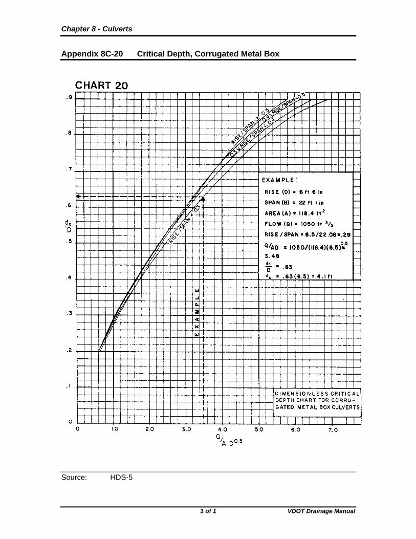
Appendix 8C-20 Critical Depth, Corrugated Metal Box
Source: HDS-5
1 of 1 VDOT Drainage Manual
Chapter 8 - Culverts
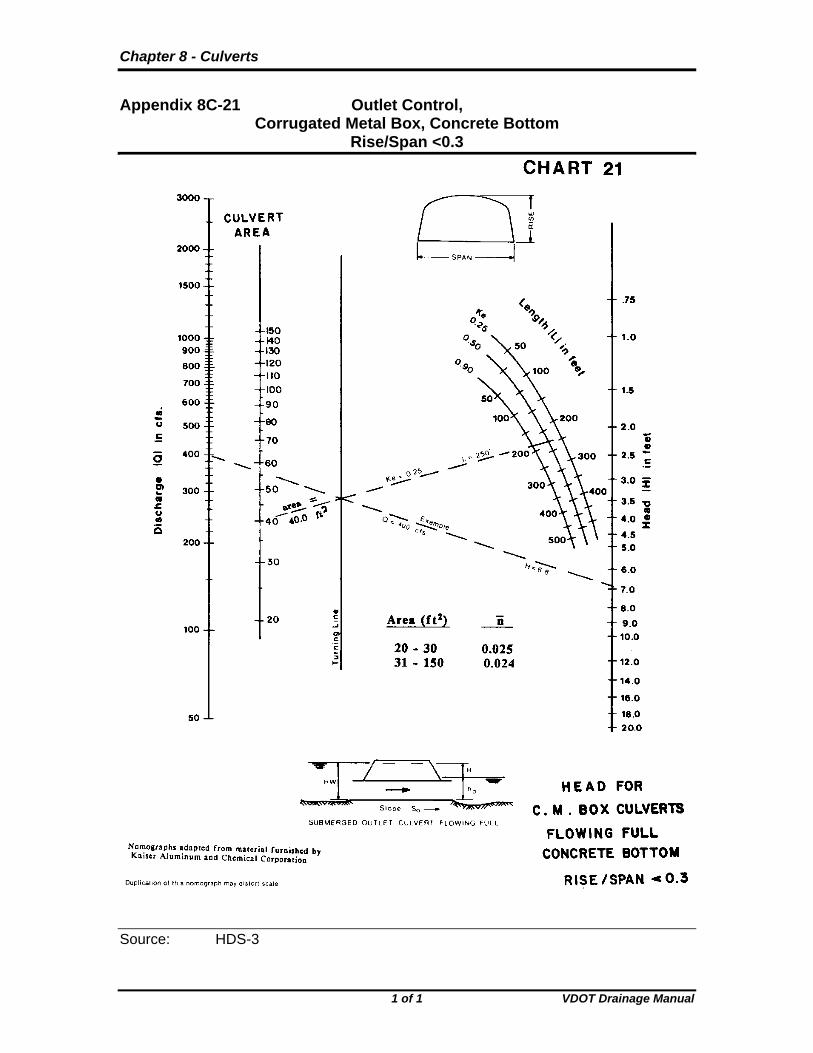
Appendix 8C-21 Outlet Control, Corrugated Metal Box, Concrete Bottom Rise/Span <0.3
Source: HDS-3
1 of 1 VDOT Drainage Manual

Chapter 8 - Culverts
Appendix 8C-22 Outlet Control, Corrugated Metal Box, Concrete Bottom 0.3≤ Rise/Span <0.4
Source: HDS-5
1 of 1 VDOT Drainage Manual

Chapter 8 - Culverts
Appendix 8C-23 Outlet Control, Corrugated Metal Box, Concrete Bottom, 0.4≤ Rise/Span <0.5
Source: HDS-5
1 of 1 VDOT Drainage Manual

Chapter 8 - Culverts
Appendix 8C-25 Outlet Control, Corrugated Metal Box, Corrugated Metal Bottom, Rise/Span <0.3
Source: HDS-5
1 of 1 VDOT Drainage Manual

Chapter 8 - Culverts
Appendix 8C-24 Outlet Control, Corrugated Metal Box, Concrete Bottom 0.5≤ Rise/Span
Source: HDS-5
1 of 1 VDOT Drainage Manual

Chapter 8 - Culverts
Appendix 8C-26 Outlet Control, Corrugated Metal Box, Corrugated Metal Box,
0.3≤ Rise/Span <0.4
Source: HDS-5
1 of 1 VDOT Drainage Manual

Chapter 8 - Culverts
1 of 1 VDOT Drainage Manual
Appendix 8C-27 Outlet Control, Corrugated Metal Box, Corrugated Metal Bottom, 0.4≤ Rise/Span <0.5
Source: HDS-5

Chapter 8 - Culverts
Appendix 8C-28 Outlet Control, Corrugated Metal Box, Corrugated Metal Bottom, 0.5≤ Rise/Span
Source: HDS-5
1 of 1 VDOT Drainage Manual

Chapter 8 - Culverts
Appendix 8C-29 Inlet Control, Oval Concrete, Long Axis Horizontal
Source: HDS-5
1 of 1 VDOT Drainage Manual
Chapter 8 - Culverts
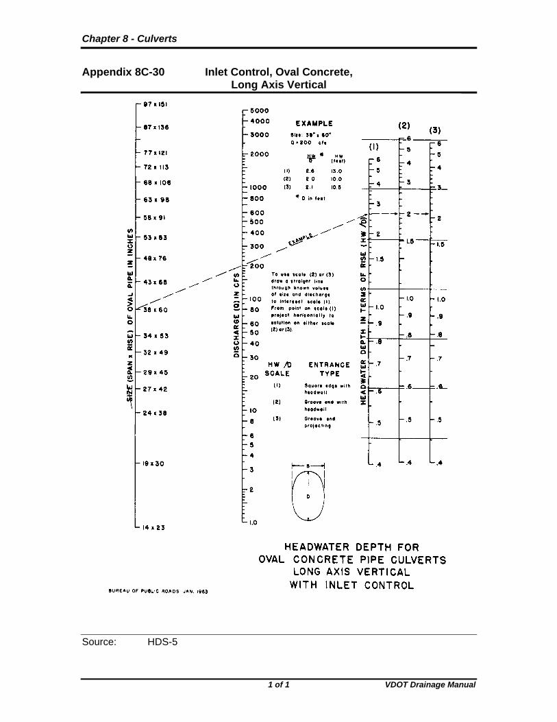
Appendix 8C-30 Inlet Control, Oval Concrete, Long Axis Vertical
Source: HDS-5
1 of 1 VDOT Drainage Manual

Chapter 8 - Culverts
Appendix 8C-31 Critical Depth, Oval Concrete, Long Axis Horizontal
Source: HDS-5
1 of 1 VDOT Drainage Manual

Chapter 8 - Culverts
Appendix 8C-35 Inlet Control, Structural Plate Pipe-Arch, 18” Corner Radius
Source: HDS-5
CHART 35
1 of 1 VDOT Drainage Manual

Chapter 8 - Culverts
Appendix 8C-47 Outlet Control, Corrugated Metal Arch, Concrete Bottom, 0.5≤ Rise/Span
Source: HDS-5
1 of 1 VDOT Drainage Manual

Chapter 8 - Culverts
Appendix 8C-34 Inlet Control, Corrugated Metal Pipe-Arch
Source: HDS-5
1 of 1 VDOT Drainage Manual

Chapter 8 - Culverts
Appendix 8C-33 Outlet Control, Oval Concrete, Long Axis Horizontal or Vertical
Source: HDS-5
1 of 1 VDOT Drainage Manual

Chapter 8 - Culverts
Appendix 8C-32 Critical Depth, Oval Concrete, Long Axis Vertical
Source: HDS-5
1 of 1 VDOT Drainage Manual

Chapter 8 - Culverts
Appendix 8C-36 Inlet Control, Structural Plate Pipe-Arch, 31” Corner Radius
Source: HDS-5
1 of 1 VDOT Drainage Manual

Chapter 8 - Culverts
Appendix 8C-37 Critical Depth, Standard Corrugated Metal Pipe-Arch
Source: HDS-5
1 of 1 VDOT Drainage Manual

Chapter 8 - Culverts
Appendix 8C-38 Critical Depth, Structural Plate Corrugated Metal Pipe-Arch, 18” Corner Radius
Source: HDS-5
1 of 1 VDOT Drainage Manual

Chapter 8 - Culverts
Appendix 8C-39 Outlet Control, Standard Corrugated Metal Pipe-Arch
Source: HDS-5
1 of 1 VDOT Drainage Manual

Chapter 8 - Culverts
Appendix 8C-40 Outlet Control, Structural Plate Corrugated Metal Pipe-Arch, 18” Corner Radius
Source: HDS-5
1 of 1 VDOT Drainage Manual

Chapter 8 - Culverts
Appendix 8C-41 Inlet Control, Corrugated Metal Arch, 0.3≤ Rise/Span <0.4
Source: HDS-5
1 of 1 VDOT Drainage Manual
Chapter 8 - Culverts
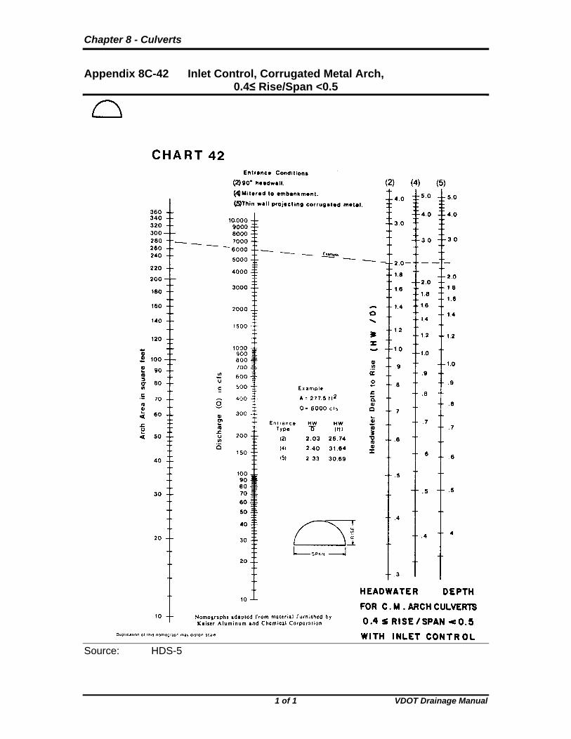
Appendix 8C-42 Inlet Control, Corrugated Metal Arch, 0.4≤ Rise/Span <0.5
Source: HDS-5
1 of 1 VDOT Drainage Manual

Chapter 8 - Culverts
Appendix 8C-43 Inlet Control, Corrugated Metal Arch, 0.5≤ Rise/Span
Source: HDS-5
1 of 1 VDOT Drainage Manual

Chapter 8 - Culverts
Appendix 8C-44 Critical Depth, Corrugated Metal Arch
Source: HDS-5
1 of 1 VDOT Drainage Manual

Chapter 8 - Culverts
Appendix 8C-45 Outlet Control, Corrugated Metal Arch, Concrete Bottom, 0.3≤ Rise/Span <0.4
Source: HDS-5
1 of 1 VDOT Drainage Manual

Chapter 8 - Culverts
Chart 8C-60 Discharge Coefficients for Roadway Overtopping
Source: HDS-5
1 of 1 VDOT Drainage Manual
Chapter 8 - Culverts
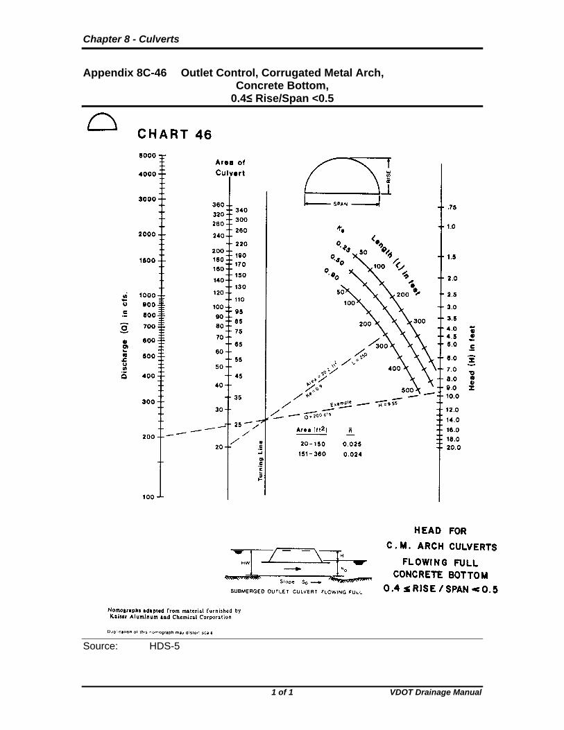
Appendix 8C-46 Outlet Control, Corrugated Metal Arch, Concrete Bottom, 0.4≤ Rise/Span <0.5
Source: HDS-5
1 of 1 VDOT Drainage Manual

Chapter 8 - Culverts
1 of 1 VDOT Drainage Manual
Appendix 8C-50 Outlet Control, Corrugated Metal Arch, Earth Bottom, 0.5≤ Rise/Span
Source: HDS-5

Chapter 8 - Culverts
Appendix 8C-49 Outlet Control, Corrugated Metal Arch, Earth Bottom, 0.4≤ Rise/Span <0.5
Source: HDS-5
1 of 1 VDOT Drainage Manual

Chapter 8 - Culverts
Appendix 8C-48 Outlet Control, Corrugated Metal Arch, Earth Bottom, 0.3≤ Rise/Span <0.4
Source: HDS-5
1 of 1 VDOT Drainage Manual

Chapter 8 - Culverts
Appendix 8C-51 Inlet Control, Structural Plate Corrugated Metal, Circular or Elliptical
Source: HDS-5
1 of 1 VDOT Drainage Manual

Chapter 8 - Culverts
Appendix 8C-52 Inlet Control, Structural Plate Corrugated Metal Arch, High and Low Profile
Source: HDS-5
1 of 1 VDOT Drainage Manual

Chapter 8 - Culverts
Appendix 8C-54 Critical Depth, Structural Plate Arch, Low and High Profile
Source: HDS-5
1 of 1 VDOT Drainage Manual

Chapter 8 - Culverts
Appendix 8C-53 Critical Depth, Structural Plate Ellipse, Long Axis Horizontal
Source: HDS-5
1 of 1 VDOT Drainage Manual

Chapter 8 - Culverts
Chart 8C-55 Throat Control, Circular Section, Side-Tapered
Source: HDS-5
1 of 1 VDOT Drainage Manual

Chapter 8 - Culverts
Chart 8C-56 Face Control, Non-Rectangular Section, Side-Tapered to Circular
Source: HDS-5
1 of 1 VDOT Drainage Manual

Chapter 8 - Culverts
Chart 8C-57 Throat Control, Box Section, Tapered Inlet
Source: HDS-5
1 of 1 VDOT Drainage Manual
Chapter 8 - Culverts
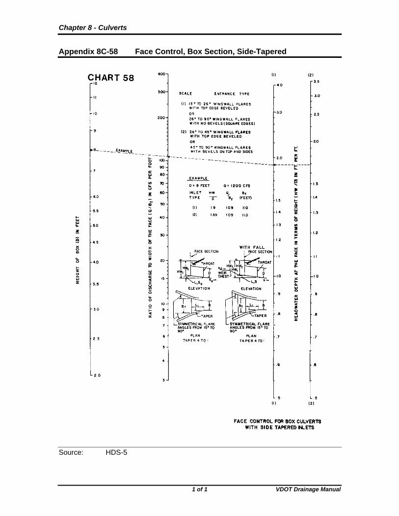
Appendix 8C-58 Face Control, Box Section, Side-Tapered
Source: HDS-5
1 of 1 VDOT Drainage Manual

Chapter 8 - Culverts
Appendix 8C-59 Face Control, Box Section, Slope-Tapered
Source: HDS-5
1 of 1 VDOT Drainage Manual

Chapter 8 - Culverts
Chart 8C-60 Discharge Coefficients for Roadway Overtopping
Source: HDS-5
1 of 1 VDOT Drainage Manual

Chapter 8 - Culverts
Appendix 8C-61 Circular Pipe Flow Chart (Diameter = 12”)
Source: HDS-3
1 of 1 VDOT Drainage Manual

Chapter 8 - Culverts
Appendix 8C-63 Circular Pipe Flow Chart (Diameter = 18”)
Source: HDS-3
1 of 1 VDOT Drainage Manual

Chapter 8 - Culverts
Appendix 8C-62 Circular Pipe Flow Chart (Diameter = 15”)
Source: HDS-3
1 of 1 VDOT Drainage Manual

Chapter 8 - Culverts
Appendix 8C-64 Circular Pipe Flow Chart (Diameter = 21”)
Source: HDS-3
1 of 1 VDOT Drainage Manual
Chapter 8 - Culverts
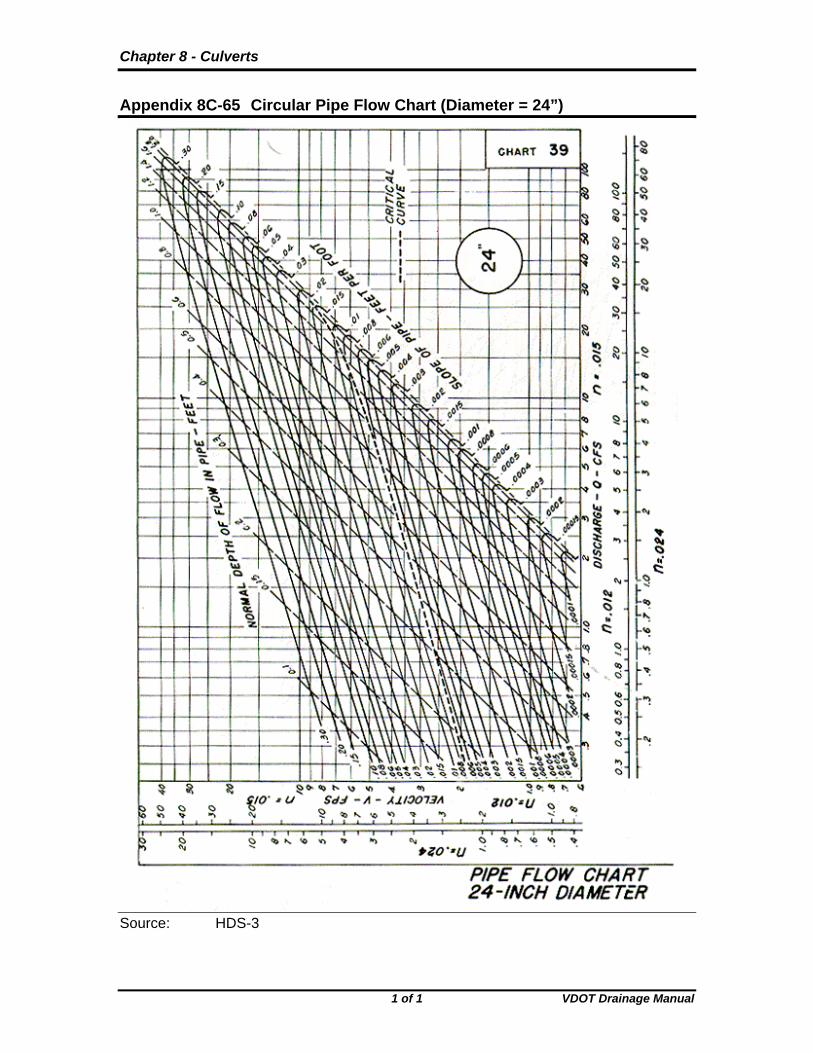
Appendix 8C-65 Circular Pipe Flow Chart (Diameter = 24”)
Source: HDS-3
1 of 1 VDOT Drainage Manual

Chapter 8 - Culverts
Appendix 8C-66 Circular Pipe Flow Chart (Diameter = 27”)
Source: HDS-3
1 of 1 VDOT Drainage Manual

Chapter 8 - Culverts
Appendix 8C-67 Circular Pipe Flow Chart (Diameter = 30”)
Source: HDS-3
1 of 1 VDOT Drainage Manual

Chapter 8 - Culverts
Appendix 8C-68 Circular Pipe Flow Chart (Diameter = 33”)
Source: HDS-3
1 of 1 VDOT Drainage Manual

Chapter 8 - Culverts
Appendix 8C-69 Circular Pipe Flow Chart (Diameter = 36”)
Source: HDS-3
1 of 1 VDOT Drainage Manual

Chapter 8 - Culverts
Appendix 8C-70 Circular Pipe Flow Chart (Diameter = 42”)
Source: HDS-3
1 of 1 VDOT Drainage Manual

Chapter 8 - Culverts
Appendix 8C-71 Circular Pipe Flow Chart (Diameter 48”)
Source: HDS-3
1 of 1 VDOT Drainage Manual

Chapter 8 - Culverts
Appendix 8C-72 Circular Pipe Flow Chart (Diameter = 54”)
Source: HDS-3
1 of 1 VDOT Drainage Manual

Chapter 8 - Culverts
Appendix 8C-73 Circular Pipe Flow Chart (Diameter = 60”)
Source: HDS-3
1 of 1 VDOT Drainage Manual

Chapter 8 - Culverts
Appendix 8C-74 Circular Pipe Flow Chart (Diameter = 66”)
Source: HDS-3
1 of 1 VDOT Drainage Manual

Chapter 8 - Culverts
Appendix 8C-75 Circular Pipe Flow Chart (Diameter = 72”)
Source: HDS-3
1 of 1 VDOT Drainage Manual

Chapter 8 - Culverts
Appendix 8C-76 Circular Pipe Flow Chart (Diameter = 84”)
Source: HDS-3
1 of 1 VDOT Drainage Manual

Chapter 8 - Culverts
Appendix 8C-77 Circular Pipe Flow Chart (Diameter = 96”)
Source: HDS-3
1 of 1 VDOT Drainage Manual

Chapter 8 - Culverts
Appendix 8C-78 Rectangular Channel Flow Chart (B=2’)
Source: HDS-3
1 of 1 VDOT Drainage Manual

Chapter 8 - Culverts
Appendix 8C-79 Rectangular Channel Flow Chart (B=3’)
Source: HDS-3
1 of 1 VDOT Drainage Manual

Chapter 8 - Culverts
Appendix 8C-80 Rectangular Channel Flow Chart (B=4’)
Source: HDS-3
1 of 1 VDOT Drainage Manual

Chapter 8 - Culverts
Appendix 8C-81 Rectangular Channel Flow Chart (B=5’)
Source: HDS-3
1 of 1 VDOT Drainage Manual

Chapter 8 - Culverts
Appendix 8C-82 Rectangular Channel Flow Chart (B=6’)
Source: HDS-3
1 of 1 VDOT Drainage Manual
Chapter 8 - Culverts
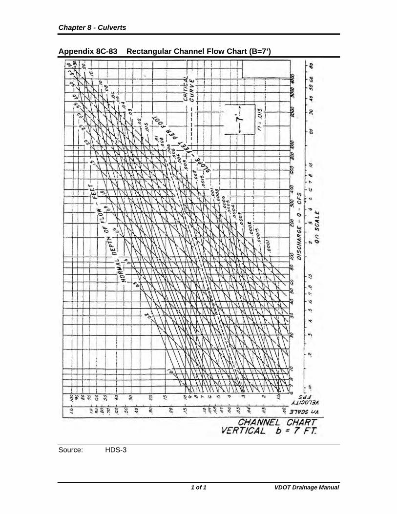
Appendix 8C-83 Rectangular Channel Flow Chart (B=7’)
Source: HDS-3
1 of 1 VDOT Drainage Manual

Chapter 8 - Culverts
Appendix 8C-84 Rectangular Channel Flow Chart (B=8’)
Source: HDS-3
1 of 1 VDOT Drainage Manual

Chapter 8 - Culverts
Appendix 8C-85 Rectangular Channel Flow Chart (B=9’)
Source: HDS-3
1 of 1 VDOT Drainage Manual
Chapter 8 - Culverts
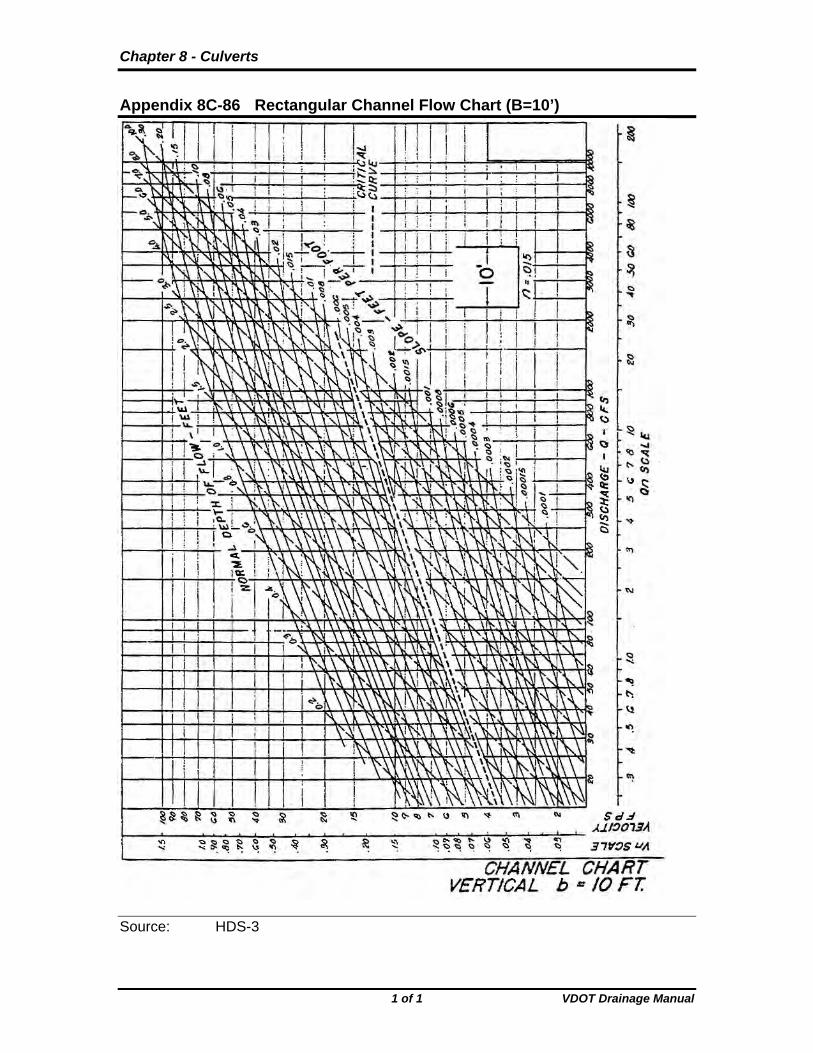
Appendix 8C-86 Rectangular Channel Flow Chart (B=10’)
Source: HDS-3
1 of 1 VDOT Drainage Manual

Chapter 8 - Culverts
Appendix 8C-87 Rectangular Channel Flow Chart (B=12’)
Source: HDS-3
1 of 1 VDOT Drainage Manual

Chapter 8 - Culverts
Appendix 8C-88 Rectangular Channel Flow Chart (B=14’)
Source: HDS-3
1 of 1 VDOT Drainage Manual

Chapter 8 - Culverts
Appendix 8C-89 Rectangular Channel Flow Chart (B=16’)
Source: HDS-3
1 of 1 VDOT Drainage Manual

Chapter 8 - Culverts
Appendix 8C-90 Rectangular Channel Flow Chart (B=18’)
Source: HDS-3
1 of 1 VDOT Drainage Manual
Chapter 8 - Culverts
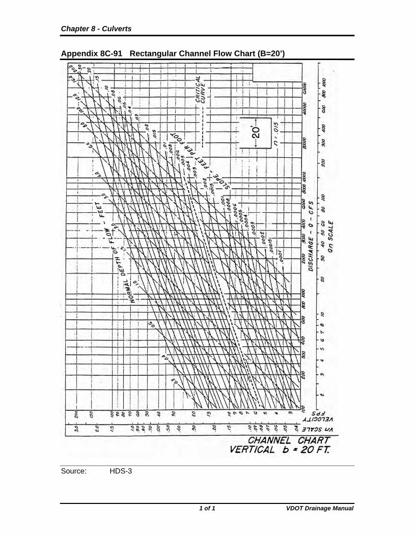
Appendix 8C-91 Rectangular Channel Flow Chart (B=20’)
Source: HDS-3
1 of 1 VDOT Drainage Manual

Chapter 8 - Culverts
Appendix 8D-1 Recommended Manning’s n-Values Type of Conduit
Wall Description
Manning’s n
Concrete Pipe Smooth walls 0.010-0.013 Concrete Boxes Smooth walls 0.012-0.015 Corrugated Metal 2 2/3 by 1/2 inch
corrugations 0.022-0.027
Pipes and Boxes Annular or Helical 6 by 1 inch corrugations 0.022-0.025 Pipe (n varies Barrel size) 5 by 1 inch corrugations 0.025-0.026 See HDS5 3 by 1 inch corrugations 0.027-0.028 6 by 2 inch structural plate 0.033-0.035 9 by 2 1/2 inch structural
plate 0.033-0.037
Corrugated Metal 2 2/3 by 1/2 inch
corrugations 0.012-0.024
Pipes, Helical Corrugations, Full Circular Flow Spiral Rib Metal Smooth walls 0.011-0.012 *Note 1: The Values indicated in this table are recommended
Manning’s “n” design values. Actual Field values for older existing pipelines may vary depending on the effects of abrasion, corrosion, deflection and joint conditions. Concrete pipe with poor joints and deteriorated walls may have “n” values of 0.014 to 0.018. Corrugated metal pipe with joint and wall problems may also have higher “n” values, and in addition, may experience shape changes which could adversely effect the general hydraulic characteristics of the culvert.
Note 2: For further information concerning Manning n values for
selected conduits consult Hydraulic Design of Highway Culverts, Federal Highway Administration, HDS No. 5, Table 4.
Source: HDS-5
1 of 1 VDOT Drainage Manual Revised 04/05

Chapter 8 - Culverts
Appendix 8D-2 Entrance Loss Coefficients (Ke), Outlet Control, Full or Partly Full
Type of Structure and Design of Entrance Coefficient
Pipe, Concrete Mitered to conform to fill slope 0.7 *End-Section conforming to fill slope 0.5 Projecting from fill, sq. cut end 0.5 Headwall or headwall and wingwalls Square-edge 0.5
Rounded (radius = D/12) 0.2 Socket end of pipe (groove-end) 0.2 Projecting from fill, socket end (groove-end) 0.2 Beveled edges, 33.7 or 45 bevels 0.2 Side-or slope-tapered inlet 0.2
Pipe, or Pipe-Arch, Corrugated Metal Projecting from fill (no headwall) 0.9 Mitered to conform to fill slope, paved or unpaved slope 0.7 Headwall or headwall and wingwalls square-edge 0.5 *End-Section conforming and to fill slope 0.5 Beveled edges, 33.7 or 45 bevels 0.2 Side-or slope-tapered inlet 0.2
Box, Reinforced Concrete Headwall parallel to embankment (no wingwalls) Square-edged on 3 edges 0.5 Rounded on 3 edges to radius of D/12 or B/12 or beveled edges on 3 sides 0.2 Wingwalls parallel (extension of sides) Square-edged at crown 0.7 Wingwalls at 10 to 25 to barrel Square-edged at crown 0.5 Wingwalls at 30 to 75 to barrel Crown edge rounded to radius of D/12 or beveled top edge 0.2 Square Edge at crown 0.4 Side-or slope-tapered inlet 0.2 *Note : “End Sections conforming to fill slope,” made of either metal or
concrete, are the sections commonly available form manufacturers. From limited hydraulic tests they are equivalent in operation to a headwall in both inlet and oulet control. Some end sections, incorporating a closed taper in their design have a superior hydraulic performance. These latter sections can be designed using the information given for the beveled inlet.
Source HDS-5
1 of 1 VDOT Drainage Manual Revised 04/05

Chapter 8 – Culverts
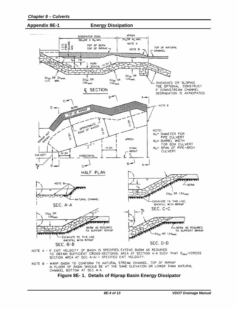
Appendix 8E-1 Energy Dissipation
8E.1 Riprap Basin Riprap basins are used for energy dissipation at the outlets of high velocity culverts. Riprap basin design is based on laboratory data obtained from full-scale prototypical installations. The principal features of riprap basins are as follows: 1. Pre-shaping and lining with riprap of median size, d50. 2. Constructing the floor at a depth of hs below the invert, where hs is the depth of
scour that would occur in a pad of riprap of size d50. 3. Sizing d50 so that 2<hs/d50<4. 4. Sizing the length of the dissipating pool to be 10(hs) or 3(Wo), whichever is larger
for a single barrel. The overall length of the basin is 15(hs) or 4Wo whichever is larger.
5. Angular rock results are approximately the same as the results of rounded material.
6. Layout details and dimensions are shown on Figure 8E-1.
For high tailwater (o
TW0.75
d ), the following applies:
1. The high velocity core of water emerging from the culvert retains its jet-like
character as it passes through the basin. 2. The scour hole is not as deep as with low tailwater and is generally longer. 3. Riprap may be required for the channel downstream of the rock-lined basin.
8E-1 of 13 VDOT Drainage Manual

Chapter 8 – Culverts
Appendix 8E-1 Energy Dissipation
8E-2 of 13 VDOT Drainage Manual
8E.2 Design Procedures and Sample Problems
The procedure shown below should be used to determine the dimension for a riprap basin energy dissipator for culvert and pipe installations with pipe velocities greater than or equal to 19 feet per second as classified in Section 8.3.2.6. Maximum Outlet Velocity within the Chapter 8 text.
Step 1: Determine input flow parameters: De or dE, Vo, Fr at the culvert outlet
Where:
dE = Equivalent depth at the brink = A
2
Note: dE = ye in Figure 8E-2
Step 2: Check TW
Determine if o
TW0.75
d
Note: do = dE in Figure 8E-2 for rectangular sections
Step 3 Determine d50
a. Use Figure 8E-2.
b. Select d50/dE. Satisfactory results will be obtained if
0.25<d50/dE<0.45.
c. Obtain hs/dE using Froude number (Fr) and Figure 8E-2.
d. Check if 2<hs/d50<4 and repeat until a d50 is found within the range.
Step 4: Size basin
a. As shown in Figure 8E-1. b. Determine length of the dissipating pool, Ls = 10hs or 3Wo
minimum. c. Determine length of basin, LB = 15hs or 4Wo minimum.
Thickness of riprap: Approach = 3d50 or 1.5dmax
Remainder = 2Wo or 1.5dmax

Chapter 8 – Culverts
Appendix 8E-1 Energy Dissipation
8E-3 of 13 VDOT Drainage Manual
Step 5: Determine exit velocity at brink (VB)
a. Basin exit depth, dB = critical depth at basin exit
b. Basin exit velocity, BB B
QV
W d
c. Compare VB with the average normal flow velocity in the natural channel (Vd)
Step 6: High tailwater design
a. Design a basin for low tailwater conditions, Steps 1-5. b. Compute equivalent circular diameter (DE) for brink area from:
2E
o o
DA d (W )
4
c. Estimate centerline velocity at a series of downstream cross sections using Figure 8E-4.
Size riprap using HEC -11 "Use of Riprap for Bank Protection.”1
Step 7: Design Filter
The design filter is necessary unless the streambed material is sufficiently well graded. To deign a filter for riprap, use the procedures in Section 4.4 of HEC-11. Dissipator geometry can also be computed using the "Energy Dissipator" module that is available in the microcomputer program HY8, Culvert Analysis.
Chapter 8 – Culverts
Appendix 8E-1 Energy Dissipation
8E-4 of 13 VDOT Drainage Manual
Figure 8E- 1. Details of Riprap Basin Energy Dissipator

Chapter 8 – Culverts
Appendix 8E-1 Energy Dissipation
8E-5 of 13 VDOT Drainage Manual
Figure 8E- 2. Riprap Basin Depth of Scour
Chapter 8 – Culverts
Appendix 8E-1 Energy Dissipation
8E-6 of 13 VDOT Drainage Manual
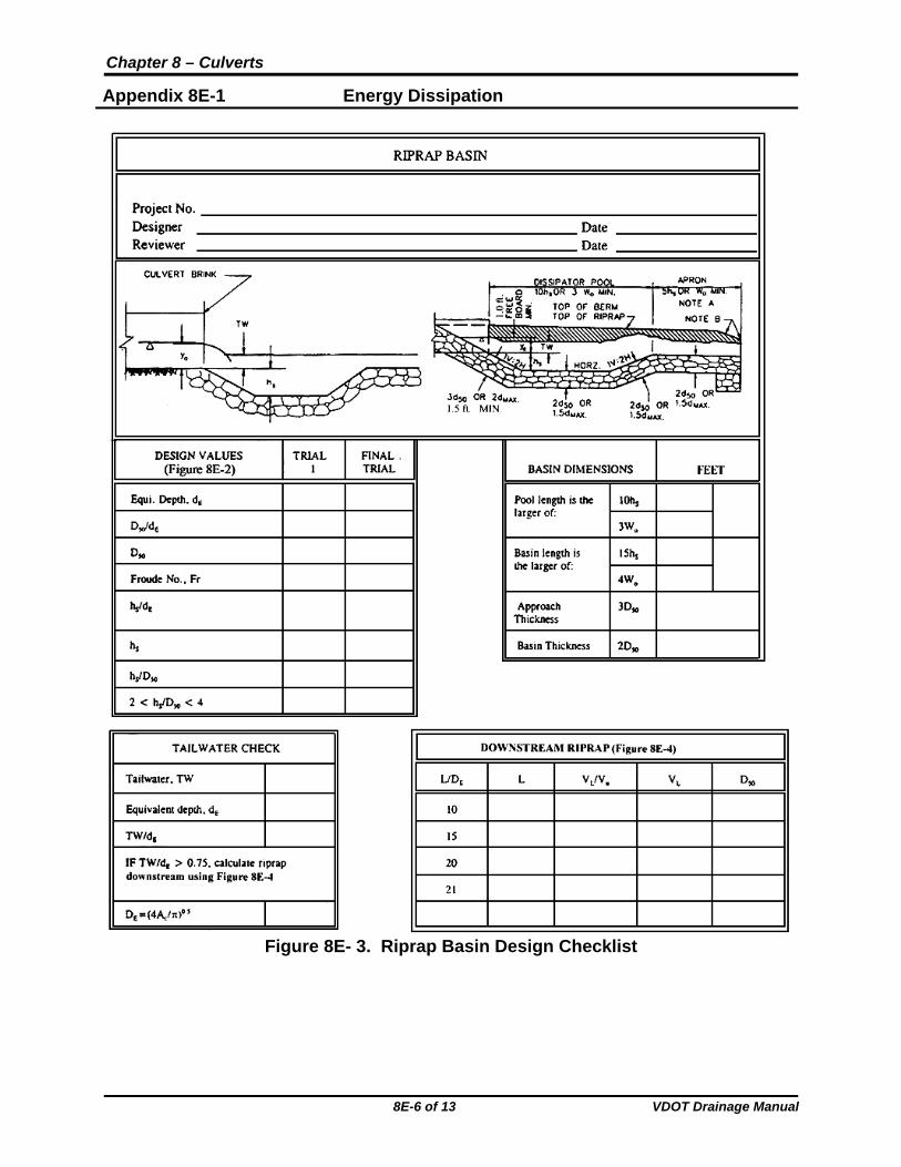
Figure 8E- 3. Riprap Basin Design Checklist

Chapter 8 – Culverts
Appendix 8E-1 Energy Dissipation
8E-7 of 13 VDOT Drainage Manual
8E.2.1 Riprap Design for Low Tailwater Condition-Sample Problem
Given: Box culvert: 8.0 ft by 6.0 ft. Design discharge Q = 800 cfs Supercritical flow in culvert Normal flow depth do = brink depth dE = 4.0 ft Tailwater depth, TW = 2.8 ft Downstream channel velocity = 18 fps
Step 1: Determine input flow parameters: De or dE, Vo, Fr at the culvert
outlet
do = dE for rectangular section do = dE = 4.0 ft.
o
Q 800V 2
A 4.0(8.0) 5 fps
or
E
V 25F 2
gd 32.2(4.0) .2 3.0
Step 2: Check TW:
Determine if E
TW0.75
d
2.80.70 0.75
4.0
Therefore, E
TW0.75
d , O.K.
Step 3: Determine d50:
a. Use Figure 8E-2 b. Try d50/dE = 0.45
5050 E
E
dd = d = 0.45(4.0) = 1.8 ft.
d
c. Obtain hS/dE using Fr = 2.2 and line 50 E0.41 d /d 0.50
hS/dE = 1.6

Chapter 8 – Culverts
Appendix 8E-1 Energy Dissipation
8E-8 of 13 VDOT Drainage Manual
d. Check if 2<hS/d50<4:
ss E
E
hh = d =1.6(4.0) 6.4 ft.
d
s
50
h 6.43.55 ft.
d 1.8
2 <3.55<4, O.K. Step 4: Size the basin:
a. As shown in Figure 8E-1 b. Determine length of dissipating pool, LS:
LS = 10hS = 10(6.4) = 64 ft. LS min.= 3Wo = 3(8) = 24 ft Therefore, use LS = 64 ft
c. Determine length of basin, LB: LB = 15hS = 15(6.4) = 96 ft
LB min. = 4Wo = 4(8) = 32 ft
Therefore, use LB = 96 ft
d. Thickness of riprap: Approach = 3d50 = 3(1.80) = 5.4 ft Remainder = 2d50 = 2(1.80) = 3.6 ft
Step 5: Determine VB:
a. dB = Critical depth at basin exit = 3.30 ft. (assuming a rectangular cross section with width WB = 24 ft.)
b. BB B
Q 800V = = =10 fps
W d 24(3.3)
c. VB =10 fps <Vd = 18 fps

Chapter 8 – Culverts
Appendix 8E-1 Energy Dissipation
8E-9 of 13 VDOT Drainage Manual
8E.2.2 Riprap Design for High Tailwater Condition-Sample Problem Given: Data on the channel and the culvert are the same as Sample
Problem 1, except that the new tailwater depth,
TW = 4.2 ft.
o
TW 4.21.05 0.75
d 4.0
Downstream channel can tolerate only 7.0 fps Steps 1 through 5 are the same as Sample Problem 8E.2.1. Step 6: High tailwater design:
a. Design a basin for low tailwater conditions, Steps 1-5 as
above: D50 = 1.8 ft, hS = 6.4 ft LS = 64 ft, LB = 96 ft
b. Compute equivalent circular diameter, DE, for brink area from: 2
2Eo o
DA d (W ) 4.0(8.0) 32 ft
4
E
4A 4(32)D 6.4 ft.
Vo = 25 fps (Sample Problem 8E.2.1). c. Estimate centerline velocity at a series of downstream cross
sections using Figure 8E-5.
1
E
L
D L
L
O
V
V VL D50
2
10 64 0.59 14.7 1.4 153 96 0.36 9.0 0.6 20 128 0.30 7.5 0.4 21 135 0.28 7.0 0.4
1 Use Wo = DE in Figure 8E- 5. 2 From Figure 8E- 6. 3 Is on a logarithmic scale so interpolations must be performed
logarithmically. d. Size riprap using HEC 11. The channel can be lined with the
same size rock used for the basin. Protection should extend at least 135 ft downstream.
This information is summarized in the worksheet for riprap basin design, Figure 8E- 4.

Chapter 8 – Culverts
Appendix 8E-1 Energy Dissipation
8E-10 of 13 VDOT Drainage Manual
Figure 8E- 4. Riprap Basin Design Worksheet, Sample Problem

Chapter 8 – Culverts
Appendix 8E-1 Energy Dissipation
8E-11 of 13 VDOT Drainage Manual
Figure 8E- 5. Distribution of Centerline Velocity for Flow from Submerged Outlets

Chapter 8 – Culverts
Appendix 8E-1 Energy Dissipation
8E-12 of 13 VDOT Drainage Manual
Figure 8E- 6. Riprap Size Versus Exit Velocity

Chapter 8 – Culverts
Appendix 8E-1 Energy Dissipation
8E-13 of 13 VDOT Drainage Manual
8E.2.3 Computer Output The dissipator geometry can be computed using the “Energy Dissipator” module, which is available in FHWA’s HY8, Culvert Analysis microcomputer program. The output of the culvert data, channel input data, and computed geometry using this module are shown below.
FHWA CULVERT ANALYSIS, HY-8, VERSION 6.0
CURRENT DATE CURRENT TIME FILE NAME FILE DATE 06-02-1997 15:23:59 ENERGY3 06-02-1997
CULVERT AND CHANNEL DATA
CULVERT NO. 1 DOWNSTREAM CHANNEL CULVERT TYPE: 8.0 ft X 6.0 ft, BOX CHANNEL TYPE: IRREGULAR CULVERT LENGTH = 300 ft BOTTOM WIDTH = 8.0 ft NO. OF BARRELS = 1.0 TAILWATER DEPTH = 2.8 ft FLOW PER BARREL= 400 cfs TOTAL DESIGN FLOW = 400 cfs INVERT ELEVATION = 172.5 ft BOTTOM ELEVATION = 172.5 ft OUTLET VELOCITY = 25 fps NORMAL VELOCITY = 32 fps OUTLET DEPTH = 4.0 ft
RIPRAP STILLING BASIN – FINAL DESIGN
THE LENGTH OF THE BASIN = 96.3 ft THE LENGTH OF THE POOL = 64.2 ft THE LENGTH OF THE APRON = 32 ft THE WIDTH OF THE BASIN AT THE OUTLET = 8.0 ft THE DEPTH OF POOL BELOW CULVERT INVERT = 6.4 ft THE THICKNESS OF THE RIPRAP ON THE APRON = 6.6 ft THE THICKNESS OF THE RIPRAP ON THE REST OF THE BASIN = 5.0 ft THE BASIN OUTLET VELOCITY = 17 fps THE DEPTH OF FLOW AT BASIN OUTLET = 6.0 ft

Chapter 8 - Culverts
Appendix 8F-1 Handling Weight for Corrugated Steel Pipe (2⅔”x½” Corrugations)
Source:
1 of 1 VDOT Drainage Manual

Chapter 8 - Culverts
Appendix 8F-2 Handling Weight for Corrugated Steel Pipe (3”x1” or 125 mm x 25 mm Corrugations)
Source:
1 of 1 VDOT Drainage Manual

Chapter 8 - Culverts
Appendix 8F-3 Dimension and Weight of Minimum Size Counterweight
Pipe Diameter (inches)
Dimensions (inches)
Concrete
D A B C Volume (cu. ft.)
Weight* (lbs.)
12 6 18 24 1.30 195 15 6 19.5 27 1.52 228 18 6 21 30 1.75 263 24 6 24 36 2.22 333 30 6 27 42 2.71 407 36 6 30 48 3.23 485 42 6 33 54 3.78 567 48 6 36 60 4.36 654 54 6 39 66 4.96 744 60 6 42 72 5.59 839 66 6 45 78 6.25 938 72 6 48 84 6.93 1040
Source:
1 of 1 VDOT Drainage Manual

Chapter 8 - Culverts
Appendix 8F-4 Diameter Dimensions and D2.5 Values for Structural Plate Corrugated Circular Pipe ( 1
29"x2 " Aluminum Corrugations)
Diameter
(feet) Nominal Actual
D2.5
Plates per
Ring 6.5 6.42 104.4 2 7.0 6.93 126.4 2
7.5 7.44 151.0 3 8.0 7.96 178.8 3 8.5 8.46 208.2 3 9.0 8.97 241.0 3 9.5 9.48 276.7 3 10.0 9.99 315.4 3 10.5 10.50 357.2 3
11.0 11.01 402.2 4 11.5 11.52 450.4 4 12.0 12.04 503.0 4 12.5 12.54 556.9 4 13.0 13.05 615.2 4 13.5 13.57 678.3 4 14.0 14.08 743.9 4
14.5 14.59 813.1 5 15.0 15.10 886.0 5
Source:
1 of 1 VDOT Drainage Manual

Chapter 8 - Culverts
Appendix 8F-5 Geometric Properties and Critical Flow Factors for Circular Conduits Flowing Full and Partly Full
Source:
1 of 1 VDOT Drainage Manual

Chapter 8 - Culverts
Appendix 8F-6 Velocity Head and Resistance Computations Factors for Circular Conduits Flowing Full and Partly Full
Source:
1 of 1 VDOT Drainage Manual

Appendix 8H-1 LD-294 Report to VDOT District Environmental Manager
1 of 3 VDOT Drainage Manual

Appendix 8H-1 LD-294 Report to VDOT District Environmental Manager
2 of 3 VDOT Drainage Manual

Appendix 8H-1 LD-294 Report to VDOT District Environmental Manager
3 of 3 VDOT Drainage Manual