appendix a - updated final safety analysis report ... · appendix a -updated fsar supplement turkey...
TRANSCRIPT

LICENSE RENEWAL APPLICATION APPENDIX A - UPDATED FSAR SUPPLEMENT
TURKEY POINT UNITS 3 & 4
Appendix A
UPDATED FINAL SAFETY ANALYSIS REPORT
SUPPLEMENT
APPENDIX A - UPDATED FSAR SUPPLEMENT I-'age A-1Page A-1APPENDIX A - UPDATED FSAR SUPPLEMENT
LICENSE RENEWAL APPLICATION APPENDIX A - UPDATED FSAR SUPPLEMENT
TURKEY POINT UNITS 3 & 4
INTRODUCTION
This appendix contains the Updated FSAR (UFSAR) Supplement required by
10 CFR 54.21(d) for the Turkey Point Units 3 and 4 License Renewal Application
(LRA). The LRA contains the technical information required by 10 CFR 54.21(a)
and (c). Chapter 3 and Appendix B of the Turkey Point LRA provide descriptions of
the programs and activities that manage the effects of aging for the period of
extended operation. Chapter 4 of the LRA contains the evaluations of the time
limited aging analyses for the period of extended operation. These LRA sections
have been used to prepare the program and activity descriptions that are contained
in the UFSAR Supplement. The UFSAR Supplement will be incorporated into the
Turkey Point Units 3 and 4 UFSAR following issuance of the renewed operating
licenses for Turkey Point. Upon inclusion of the UFSAR Supplement in the Turkey
Point UFSAR, changes to the descriptions of the programs and activities for their
implementation will be made in accordance with 10 CFR 50.59.
APPENDIX A - UPDATED FSAR SUPPLEMENT Page A-z
LICENSE RENEWAL APPLICATION APPENDIX A - UPDATED FSAR SUPPLEMENT
TURKEY POINT UNITS 3 & 4
UFSAR CHAPTER 4.0 CHANGES
APPENDIX A - UPDATED ESAR SUPPLEMENT Page A-3Page A-3APPENDIX A - UPDATED FSAR SUPPLEMENT
LICENSE RENEWAL APPLICATION APPENDIX A - UPDATED FSAR SUPPLEMENT
TURKEY POINT UNITS 3 & 4
For the combination of normal plus design earthquake loadings, the stresses in the
support structures are kept within the limits of the applicable codes.
For the combination of normal plus no-loss-of-function earthquake loadings, the
stresses in the support structures are limited to values necessary to ensure their
integrity, and to keep the stresses in the Reactor coolant system components within
the allowable limits as given in Appendix 5A.
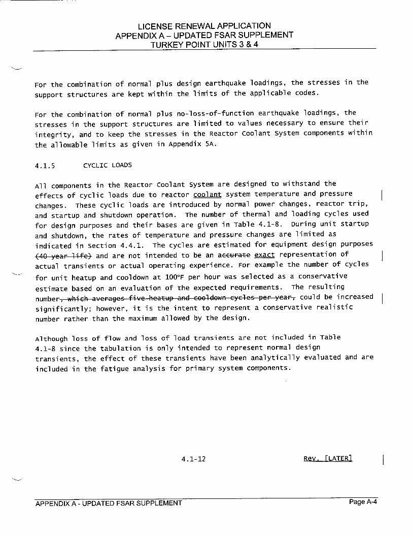
4.1.5 CYCLIC LOADS
All components in the Reactor coolant system are designed to withstand the
effects of cyclic loads due to reactor coolant system temperature and pressure
changes. These cyclic loads are introduced by normal power changes, reactor trip,
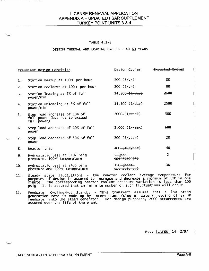
and startup and shutdown operation. The number of thermal and loading cycles used
for design purposes and their bases are given in Table 4.1-8. During unit startup
and shutdown, the rates of temperature and pressure changes are limited as
indicated in section 4.4.1. The cycles are estimated for equipment design purposes
(40 year life) and are not intended to be an accurate exat representation of
actual transients or actual operating experience. For example the number of cycles
for unit heatup and cooldown at 100°F per hour was selected as a conservative
estimate based on an evaluation of the expected requirements. The resulting
number, which averages five heatup and co.ldown cycles per year, could be increased
significantly; however, it is the intent to represent a conservative realistic
number rather than the maximum allowed by the design.
Although loss of flow and loss of load transients are not included in Table
4.1-8 since the tabulation is only intended to represent normal design
transients, the effect of these transients have been analytically evaluated and are
included in the fatigue analysis for primary system components.
4.1-12 Re v. L AL I.ER
APPENDIX A - UPDATED FSAR SUPPLEMENT Page A-4Page A-4APPENDIX A - UPDATED FSAR SUPPLEMENT
LICENSE RENEWAL APPLICATION APPENDIX A - UPDATED FSAR SUPPLEMENT
TURKEY POINT UNITS 3 & 4
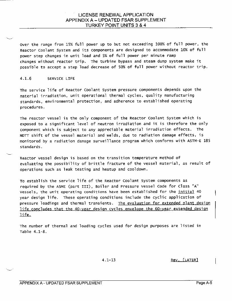
Over the range from 15% full power up to but not exceeding 100% of full power, the Reactor coolant System and its components are designed to accommodate 10% of full power step changes in unit load and 5% of full power per minute ramp changes without reactor trip. The turbine bypass and steam dump system make it possible to accept a step load decrease of 50% of full power without reactor trip.
4.1.6 SERVICE LIFE
The service life of Reactor coolant System pressure components depends upon the
material irradiation, unit operational thermal cycles, quality manufacturing standards, environmental protection, and adherence to established operating procedures.
The reactor vessel is the only component of the Reactor Coolant System which is exposed to a significant level of neutron irradiation and it is therefore the only
component which is subject to any appreciable material irradiation effects. The NDTT shift of the vessel material and welds, due to radiation damage effects, is monitored by a radiation damage surveillance program which conforms with ASTM-E 185 standards.
Reactor vessel design is based on the transition temperature method of evaluating the possibility of brittle fracture of the vessel material, as result of operations such as leak testing and heatup and cooldown.
To establish the service life of the Reactor coolant system components as required by the ASME (part III), Boiler and Pressure vessel Code for Class "A"
vessels, the unit operating conditions have been established for the initial 40 year design life. These operating conditions include the cyclic application of pressure loadings and thermal transients. The evaluation for extended plant design
life concludes that the 40-year design cycles envelope the 60-year extended design life_
The number of thermal and loading cycles used for design purposes are listed in Table 4.1-8.
4.1-13 Rev. FLATER1
APPENDIX A - UPDATED FSAR SUPPLEMENT Page A-5Page A-5APPENDIX A - UPDATED FSAR SUPPLEMENT
LICENSE RENEWAL APPLICATION APPENDIX A - UPDATED FSAR SUPPLEMENT
TURKEY POINT UNITS 3 & 4
TABLE 4.1-8
DESIGN THERMAL AND LOADING CYCLES - 40 60Q YEARS
Transient Desian condition
1. station heatup at 100OF per hour
2. station cooldown at 100OF per hour
3. Station loading at 5% of full power/min
4. Station unloading at 5% of full power/min
5. Ste full fullI
load increase of 10% of power (but not to exceed power)
6. Step load decrease of 10% of full power
•_ 7. Step load decrease of 50% of full power
8. Reactor trip
9. Hydrostatic test at 3107 psig pressure, 100OF temperature
10. Hydrostatic test at 2435 psig pressure and 400OF temperature
Design cycles
200 (5 y,,
200 (/r)/,,'
14,500 (!/day)
14,500 (!/day)
2000-(1/week}
2,000 (1/week}
200 (•/.yea..
400 (/...ear"
ope rati enal
150 (potopt. r-t cn!
Expecte r -
80
80
2500
2500
&00
o00
20
40
2
30
11. steady state fluctuations - the reactor coolant average temperature purposes of design is assumed to increase and decrease a maximum of 6aF in minute. The corresponding reactor coolant pressure variation is less than psig. It is assumed that an infinite number of such fluctuations will occur.
for one 100
12. Feedwater cycling/Hot Standby - This transient assumes that a low steam generation rate is made up by intermittant (slug of water) feeding of 32 OF eedwater into the steam generator. For design purposes, 2000 occurrences are
assumed over the life of the plant.
Rev. [LATER] 14 2/97
APPENDIX A - UPDATED FSAR SUPPLEMENT Page A-6Page A-6APPENDIX A - UPDATED FSAR SUPPLEMENT
LICENSE RENEWAL APPLICATION APPENDIX A - UPDATED FSAR SUPPLEMENT
TURKEY POINT UNITS 3 & 4
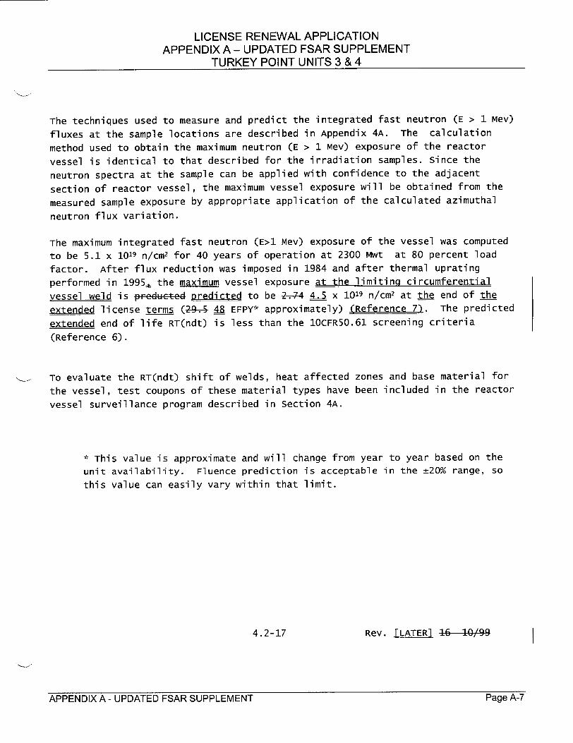
The techniques used to measure and predict the integrated fast neutron (E > 1 Mev) fluxes at the sample locations are described in Appendix 4A. The calculation method used to obtain the maximum neutron (E > 1 Mev) exposure of the reactor
vessel is identical to that described for the irradiation samples. since the
neutron spectra at the sample can be applied with confidence to the adjacent
section of reactor vessel, the maximum vessel exposure will be obtained from the
measured sample exposure by appropriate application of the calculated azimuthal
neutron flux variation.
The maximum integrated fast neutron (E>1 Mev) exposure of the vessel was computed
to be 5.1 x 10¹⁹ n/cm2 for 40 years of operation at 2300 Mwt at 80 percent load
factor. After flux reduction was imposed in 1984 and after thermal uprating
performed in 1995, the maximum vessel exposure at the limiting circumferential
vessel weld is predeted predicted to be 2-74 4.5 x 10¹⁹ n/cm2 at the end of the
extended license terms (2-9. 4" EFPY* approximately) (Reference 7). The predicted
extended end of life RT(ndt) is less than the 10CFR50.61 screening criteria
(Reference 6).
To evaluate the RT(ndt) shift of welds, heat affected zones and base material for
the vessel, test coupons of these material types have been included in the reactor
vessel surveillance program described in section 4A.
* This value is approximate and will change from year to year based on the
unit availability. Fluence prediction is acceptable in the _±20% range, so
this value can easily vary within that limit.
4.2-17 Rev. i[ LAE99
APPENDIX A - UPDATED FSAR SUPPLEMENT Page A-iPage A-7APPENDIX A - UPDATED FSAR SUPPLEMENT
LICENSE RENEWAL APPLICATION APPENDIX A - UPDATED FSAR SUPPLEMENT
TURKEY POINT UNITS 3 & 4
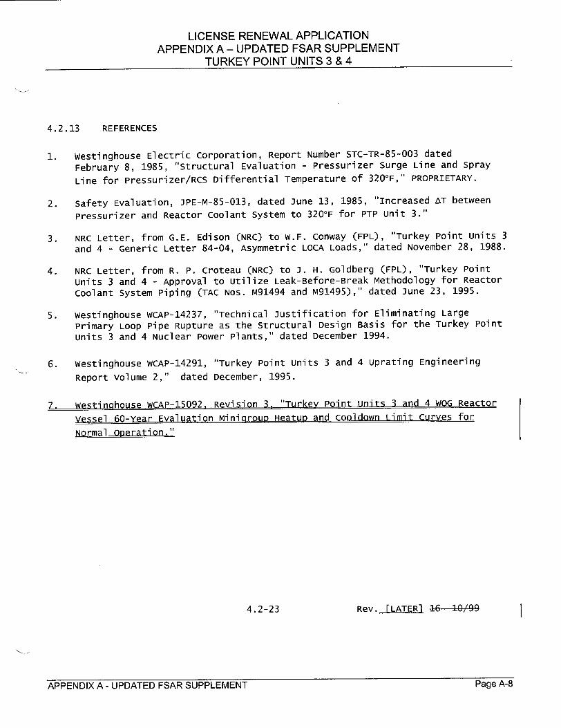
4.2.13 REFERENCES
1. westinghouse Electric Corporation, Report Number STC-TR-85-003 dated
February 8, 1985, "Structural Evaluation - Pressurizer Surge Line and spray
Line for Pressurizer/RCS Differential Temperature of 3200F," PROPRIETARY.
2. safety Evaluation, JPE-M-85-013, dated June 13, 1985, "increased AT between
Pressurizer and Reactor coolant System to 32 0 OF for PTP unit 3."
3. NRC Letter, from G.E. Edison (NRC) to W.F. Conway (FPL), "Turkey Point Units 3
and 4 - Generic Letter 84-04, Asymmetric LOCA Loads," dated November 28, 1988.
4. NRC Letter, from R. P. Croteau (NRC) to J. H. Goldberg (FPL), "Turkey Point
units 3 and 4 - Approval to utilize Leak-Before-Break Methodology for Reactor
coolant system Piping (TAC Nos. M91494 and M91495)," dated June 23, 1995.
5. westinghouse WCAP-14237, "Technical justification for Eliminating Large
Primary Loop Pipe Rupture as the structural Design Basis for the Turkey Point
units 3 and 4 Nuclear Power Plants," dated December 1994.
6. westinghouse WCAP-14291, "Turkey Point units 3 and 4 Uprating Engineering
Report volume 2," dated December, 1995.
7. westinghouse WCAP-15092, Revision 3. "Turkey Point units 3 and 4 WOG Reactor
vessel 60-Year Evaluation Minigroup Heatup and Cooldown Limit Curves for
Normal Operation."
4.2-23 Rev. ATE R099
APPENDIX A - UPDATED FSAR SUPPLEMENT Page A-8Page A-8APPENDIX A - UPDATED FSAR SUPPLEMENT
LICENSE RENEWAL APPLICATION APPENDIX A - UPDATED FSAR SUPPLEMENT
TURKEY POINT UNITS 3 & 4
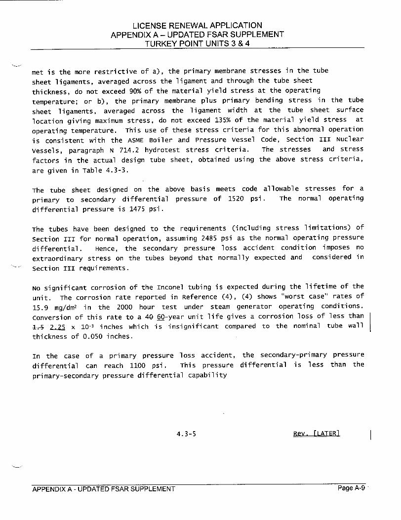
met is the more restrictive of a), the primary membrane stresses in the tube
sheet ligaments, averaged across the ligament and through the tube sheet
thickness, do not exceed 90% of the material yield stress at the operating
temperature; or b), the primary membrane plus primary bending stress in the tube
sheet ligaments, averaged across the ligament width at the tube sheet surface
location giving maximum stress, do not exceed 135% of the material yield stress at
operating temperature. This use of these stress criteria for this abnormal operation
is consistent with the ASME Boiler and Pressure vessel code, section III Nuclear
vessels, paragraph N 714.2 hydrotest stress criteria. The stresses and stress
factors in the actual design tube sheet, obtained using the above stress criteria,
are given in Table 4.3-3.
The tube sheet designed on the above basis meets code allowable stresses for a
primary to secondary differential pressure of 1520 psi. The normal operating
differential pressure is 1475 psi.
The tubes have been designed to the requirements (including stress limitations) of
section III for normal operation, assuming 2485 psi as the normal operating pressure
differential. Hence, the secondary pressure loss accident condition imposes no
extraordinary stress on the tubes beyond that normally expected and considered in
Section III requirements.
No significant corrosion of the Inconel tubing is expected during the lifetime of the
unit. The corrosion rate reported in Reference (4), (4) shows "worst case" rates of
15.9 mg/dm2 in the 2000 hour test under steam generator operating conditions.
Conversion of this rate to a 40 60-year unit life gives a corrosion loss of less than
2. 25 x 10-3 inches which is insignificant compared to the nominal tube wall
thickness of 0.050 inches.
In the case of a primary pressure loss accident, the secondary-primary pressure
differential can reach 1100 psi. This pressure differential is less than the
primary-secondary pressure differential capability
4.3-5 Rev. rLATR
APPENDIX A - UPDATED ESAR SUPPLEMENT Page A43Page A-9APPENDIX A - UPDATED FSAR SUPPLEMENT
LICENSE RENEWAL APPLICATION APPENDIX A - UPDATED FSAR SUPPLEMENT
TURKEY POINT UNITS 3 & 4
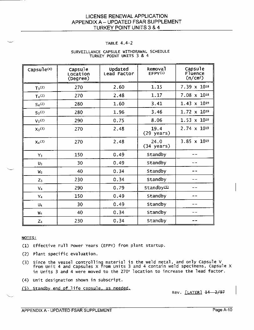
TABLE 4.4-2
SURVEILLANCE CAPSULE WITHDRAWAL SCHEDULE TURKEY POINT UNITS 3 & 4
capsule( 4) capsule updated Removal Capsule Location Lead Factor EFPY( 1) Fl uence (Degree) (n/cm2)
T3( 2) 270 2.60 1.15 7.39 x 10¹⁸
T4(2) 270 2.48 1.17 7.08 x 10¹⁸
S4(2) 280 1.60 3.41 1.43 x 10¹⁹
S3(2) 280 1.96 3.46 1.72 x 10¹⁹
V3(2) 290 0.75 8.06 1.53 x 1019
X3(3) 270 2.48 19.4 2.74 x 10¹⁹ (29 years)
X4(3) 270 2.48 24.0 3.85 x 10¹⁹ (34 years)
Y3 150 0.49 standby -
U3 30 0.49 standby -
W3 40 0.34 standby -
z3 230 0.34 Standby -
V4 290 0.79 standby4u -
Y4 150 0.49 Standby -
U4 30 0.49 Standby -
w4 40 0.34 standby -
z4 230 0.34 standby -
NOTES:
(1) Effective Full Power Years (EFPY) from plant startup.
(2) Plant specific evaluation.
(3) since the vessel controlling material is the weld metal, and only capsule V from unit 4 and capsules x from units 3 and 4 contain weld specimens, capsule x in units 3 and 4 were moved to the 2700 location to increase the lead factor.
(4) unit designation shown in subscript.
(5) standby end of life capsule, as needed.Rev. FLA-TER]. A 2/97
APPENDIX A - UPDATED FSAR SUPPLEMENT Page A-bPage A-1 0APPENDIX A - UPDATED FSAR SUPPLEMENT
LICENSE RENEWAL APPLICATION APPENDIX A - UPDATED FSAR SUPPLEMENT
TURKEY POINT UNITS 3 & 4
UFSAR CHAPTER 5.0 CHANGES
APPNDI A UPATE.FSR.SPPLMEN I-ag is- 1Page A-1 ]APPENDIX A - UPDATED FSAR SUPPLEMENT
LICENSE RENEWAL APPLICATION APPENDIX A - UPDATED FSAR SUPPLEMENT
TURKEY POINT UNITS 3 & 4
5.1.3 CONTAINMENT DESIGN ANALYSES
This section discusses analytical techniques, references and design philosophy for
the containment building design/analyses. The results of the original analyses and
the 1994 re-analysis are provided in Section 5.1.4 and Appendix 5H, respectively.
The original design criteria, analyses, and construction drawings have been
reviewed by Bechtel's consultants, T. Y. Lin, Kulka, Yang & Associate.
original Analysis
The original containment structure analyses fall into two parts, axisymmetric and
non-axisymetric. The axisymmetric analysis is performed through the use of a
finite element computer program for the individual loads and is described in
section 5.1.3.1. The axisymmetric finite element approximation of the containment
structure shell does not consider the buttresses, penetrations,
brackets and anchors. These items of configuration, and lateral loads due to
earthquakes or winds, and any concentrated loads, are considered in the
non-axisymmetric analysis described in Section 5.1.3.2.
1994 Re-analysis
During the performance of the 20th year tendon surveillance of the Turkey Point
units 3 and 4 containment structure post-tensioning systems, a number of measured
normalized tendon lift-off forces were below the predicted lower limit (PLL).
Evaluation of the 20th year surveillance results concluded that the probable cause
for the low tendon lift-off forces was due to an increased tendon wire steel relaxation loss caused by average tendon temperatures higher than originally
considered. The evaluations also concluded that the containment post-tensioning
system will provide sufficient prestress force to maintain Turkey Point licensing
basis requirements through the 25th year tendon surveillance. The evaluations
recommended that a structural re-analysis of the containment structure be performed
to determine the minimum required prestress forces, and to establish that the
containment structure will continue to meet the licensing basis requirements
through the end of the licensed plant 4 life (see Appendix 5H for additional detail).
5.1.3-1 Rev. •LATLJ 13-10/96
APPENDIX A - UPDATED FSAR SUPPLEMENT Page A-12Page A-1 2APPENDIX A - UPDATED FSAR SUPPLEMENT
LICENSE RENEWAL APPLICATION APPENDIX A - UPDATED FSAR SUPPLEMENT
TURKEY POINT UNITS 3 & 4
A containment structure re-analysis was completed in 1994 and Safety Evaluation
JPN-PTN-SECJ-94-027 (Reference 9) has been performed to document the results of
this re-analysis.
The containment re-analysis used a three dimensional (3-D) finite element model of
the containment structure. The 3-D model consisted of the cylindrical wall
(including buttresses), ring girder, dome, base slab, and the major penetrations
(equipment hatch and personnel hatch). The containment re-analysis did not include
a new evaluation of the base slab since it was not affected by the post-tensioning
system. The base slab was included in the 3-D model to provide a realistic
boundary condition for the model.
Appendix 5H provides a summary of the containment re-analysis methodology,
analytical techniques, references, and results.
The portions of Sections 5.1.3 and 5.1.4 relative to the original analysis of the
containment structure which are affected by the 1994 re-analysis (see Appendix 5H)
are annotated in the pertinent sections.
License Renewal Analysis
Durina the License Renewal process, the Turkey Point units 3 and 4 containment
tendons were analyzed for a 60-year life. The analysis concluded that the
containment tendons will continue to meet the licensing basis requirements through
the licensed plant 60-year life. (subsection 16.3.4)
5.1.3.1 Axisymmetric Analysis (original analysis)
The finite element technique is a general method of structural analysis in which
the continuous structure is replaced by a system of elements (members) connected at
a finite number of nodal points (joints). Standard conventional analysis of frames
and trusses can be considered to be examples of the finite element method. In the
application of the method to an axisymmetric solid (e.g., a concrete containment
structure) the continuous structure is replaced by a system of rings of triangular
cross-section which are interconnected along circumferential joints. Based on
energy principles, work equilibrium equations are formed in which the radial and
axial displacements at the circumferential joints are the unknowns. The results of
the solution of this set of equations is the deformation of the structure under the
given loading
5.1.3-1a Rev. T 1-0/96
APPENDIX A - UPDATED FSAR SUPPLEMENT P'age A-1 3

LICENSE RENEWAL APPLICATION APPENDIX A - UPDATED FSAR SUPPLEMENT
TURKEY POINT UNITS 3 & 4
Assuming that the jacking stress for the tendons is 0.80 f', or 192,000 psi and
using the above prestress loss parameters, the following tabulation shows the
magnitude of the design losses and the final effective prestress at end of 40 years
for a typical dome, hoop, and vertical tendon.L
Dome Hoop vertical Allowable (Ksi) (Ksi) (Ksi) (Ksi)
Temporary Jacking Stress 192 192 192 192
Friction LOSS 19 21.3(l) 21
Seating LOSS - 0 0
Elastic Loss (average) 14.7 15.3 6.6
creep Loss 19.2 19.2 19.2(4)
shrinkage Loss 3.0 3.0 3.0
Relaxation LOSS(3) 12.5 12.5 12.5
Final Effective Stress (2) 123.6 120.7 129.7 144.0
(1) Average of adjacent tendons
(2) This force does not include the effect of pressurization which increases
the prestress force.
(3) see footnote (1) in listing at beginning of Section 5.1.4.4.
(4) To determine tendon surveillance lift-off acceptance criteria, the creep loss for the vertical tendons has been adjusted. For further details, see Reference 11 of safety evaluation JPN-PTN-SECJ-94-027 (Reference 9 on Page 5.1.3-38).
(5) The 40-year prestress losses depicted in the tabulation were utilized to
calculate 60-year prestress losses for license renewal.
To provide assurance, of achievement of the desired level of Final Effective
Prestress and that ACI 318-63 requirements are met, a written procedure was
prepared for guidance of post-tensioning work. The procedures provided nominal
values for end anchor forces in terms of pressure gage readings for calibrated
jack-gage combinations. Force measurements were made at the end anchor, of course,
since that is the only practical location for such measurements.
5.1.4-7 Rev. ALA-E10/96
APPENDIX A - UPDATED FSAR SUPPLEMENT Page A-14Page A-14APPENDIX A - UPDATED FSAR SUPPLEMENT

LICENSE RENEWAL APPLICATION APPENDIX A - UPDATED FSAR SUPPLEMENT
TURKEY POINT UNITS 3 & 4
5.1.7.4 Tendon surveillance
Provisions are made for an in-service tendon surveillance program, throughout the
life of the plant that will maintain confidence in the integrity of the
containment structure. This program is supplemented by a corrosion control
prpgram. -(See subsection 16.2.1.4 for program description relating to license renewal. )
The following quantity of tendons have been provided over and above the structural
requirements:
Horizontal - Three 120 degree tendons comprising one complete hoop
vertical - Three tendons spaced approximately 120 degrees apart.
Dome - Three tendons spaced approximately 120 degrees apart.
system.
Beginning with the twentieth year tendon surveillance, inspections and lift-off
readings are performed on five horizontal, four vertical, and three dome tendons.
The tendons chosen for surveillance are a random but representative sample.
5.1.7-5 Rev L11 11/9 3
APPENDIX A - UPDATED FSAR SUPPLEMENT Page A-ThPage A-1l5APPENDIX A - UPDATED FSAR SUPPLEMENT
LICENSE RENEWAL APPLICATION APPENDIX A - UPDATED FSAR SUPPLEMENT
TURKEY POINT UNITS 3 & 4
The surveillance program for structural integrity and corrosion protection consists of the following operations to be performed during each inspection:
(a) Lift-off readings will be taken for all of the twelve tendons.
(b) one tendon of each directional group will be relaxed and one wire from each
relaxed tendon will be removed as samples for inspection, since these tendons are re-tensioned to their original lift-off forces these samples
need not be replaced.
(c) After the inspection, the tendons will be retensioned to the stress level measured at the lift-off reading and then checked by a final lift-off reading.
(d) should the inspection of one of the wires reveal any significant corrosion (pitting, or loss of area), further inspection of the other
two sets will be made to determine the extent of the corrosion and its significance to the load-carrying capacity of the structure. samples of corroded wire will be tested to failure to evaluate the effects of any corrosion on the tensile strength of the wire.
The inspection of the four vertical tendons in the wall is sufficient to indicate
any tendon corrosion that could possibly appear longitudinally along the full
height of the structure. Furthermore, the vertical tendon,• extend below the ground
water table where . .rr.sion is most likely to e occur, 4- at all.Therefore, the twelve tendons arranged as described will provide adequate corrosion surveillance.
5.1.7-6 Rev. 16-10/99
APPENDIX A - UPDATED FSAR SUPPLEMENT Page A-16APPENDIX A - UPDATED FSAR SUPPLEMENT Page A- 16
LICENSE RENEWAL APPLICATION APPENDIX A - UPDATED FSAR SUPPLEMENT
TURKEY POINT UNITS 3 & 4
The anchorage details permit some degree of accessibility for inspection of all
tendons in the containment structure. corrective action will be taken if and when so indicated by the surveillance program, and an adequate containment structure will be maintained throughout the life of the plant.
The following steps are taken to protect the tendons and the reinforcing steel in
the containment structure from corrosion due to stray current and moisture
environment.
A tendon protection sheathing filler compound encloses the whole length of every
tendon. This compound will not deteriorate during the forty year-life of the unit.
As its chemical composition is about 98% petroleum jelly, it will possess the
normal stability of the linear hydrocarbons subjected to normal ambient temperature
levels. The electrical resistivity of the compound is relatively high. This
prevents the possibility of galvanic corrosion that would be detrimental to the tendons. Anodic corrosion centers that could develop on the surface of tendons
surrounded by a good electrolyte material will not form in the presence of the
protective sheathing filler.
All metallic components such as the tendon trumplate, reinforcing bars and liner
plate are interconnected to form an electrically continuous cathodic structure,
thereby avoiding inherent difficulties associated with isolation and interference
of these members. This interconnection of the steel work with the liner plate
ensures that cathodic protection currents will not be allowed to flow through any
isolated member to cause electrolytic corrosion.
5.1.7-7 Rev. A 1WR96
APPENDIX A - UPDATED FSAR SUPPLEMENT Page A-17Page A-1 7APPENDIX A - UPDATED FSAR SUPPLEMENT

LICENSE RENEWAL APPLICATION APPENDIX A - UPDATED FSAR SUPPLEMENT
TURKEY POINT UNITS 3 & 4
the combination of normal loads and design earthquake loading. critical equipment
needed for this purpose is required to operate within normal design limits.
In the case of the maximum hypothetical earthquake, it is only necessary to ensure
that critical components do not lose their capability to perform their safety
function, i.e., shut the unit down and maintain it in a safe condition. This
capability is ensured by maintaining the stress limits as shown in Table 5A-1. No
rupture of a class I pipe is caused by the occurrence of the maximum hypothetical
earthquake.
careful design and thorough quality control during manufacture and construction
and inspection during unit life, ensures that the independent occurrence of a reactor coolant pipe rupture is extremely remote. Leak-Before-Break (LBB) criteria
has been applied to the reactor coolant system piping based on fracture mechanics
technology and material toughness. That evaluation, together with the leak detection system, demonstrates that the dynamic effects of postulated primary loop
pipe ruptures may be eliminated from the design basis (Reference 5A-2). This Leak
Before-Break evaluation was approved by the NRC for use at Turkey Point (Reference
5A-5). This evaluation has been revised for the period of extended operation~as
discussed in subsection 16.3.8.
5A-1.3.2.2 Reactor vessel Internals
5A-1.3.2.2.1 Reactor vessel Internals Design criteria
The internals and core are designed for normal operating conditions and subjected
to load of mechanical, hydraulic, and thermal origin. The response of the structure under the design earthquake is included in this category.
The stress criteria established in the ASME Boiler and Pressure Vessel code,
section III, Article 4, have been adopted as a guide for the design of the
internals and core with the exception of those fabrication techniques and materials
which are not covered by the code. Earthquake stresses are combined in the most
conservative way and are considered primary stresses.
5A-7 Rev. rT 14 2/97
Page A-18APPENDIX A -UPDATED FSAR SUPPLEMENT
LICENSE RENEWAL APPLICATION APPENDIX A - UPDATED FSAR SUPPLEMENT
TURKEY POINT UNITS 3 & 4
to accommodate the forces exerted by the restrained liner plate, and that
careful attention be paid to details at corners and connections to minimize
the effects of discontinuities.
The most appropriate basis for establishing allowable liner plate strains is
considered to be that portion of the ASME Boiler and Pressure vessel Code,
Section III, Nuclear vessels, Article 4. specifically the following sections
are adopted as guides in establishing the allowable strain limits:
Paragraph N 412 (M) Thermal Stress
Paragraph N414.5 Peak Stress Intensity Table N 413
Figure N 414, N 415 (A)
Paragraph N 412 (n)
Paragraph N 415.1
Implementation of the ASME Code requires that the liner material be
prevented from experiencing significant distortion due to thermal load
and that the stresses be considered from a fatigue standpoint.
(Paragraph N412 (m) (2) ).
The following fatigue loads are considered in the 6 design n of
the liner plate (See subsection 16.3.5 for additional detailsa:
(a) Thermal cycling due to annual outdoor temperature variations. The
number of cycles for this loading is 40 60 cycles for the unit life
of 40 60 years.
(b) Thermal cycling due to the containment interior temperature
variation during the startup and shutdown of the reactor system.
The number of cycles for this loading is assumed to be 500 cycles.
(c) Thermal cycling due to the MHA will be assumed to be one cycle.
513-16 Rev. F LA-TER1
APPENDIX A - UPDATED FSAR SUPPLEMENT Page A-1YPage A- 19APPENDIX A -UPDATED FSAR SUPPLEMENT
LICENSE RENEWAL APPLICATION APPENDIX A - UPDATED FSAR SUPPLEMENT
TURKEY POINT UNITS 3 & 4
(d) Thermal load cycles in the piping systems are somewhat isolated from the liner plate penetrations by the concentric sleeves between the pipe and the liner plate. The attachment sleeve is designed in accordance with ASME Section III fatigue considerations. All penetrations are
reviewed for a conservative number of cycles to be expected during the 60-yearunit life.
The thermal stresses in the liner plate fall into the categories considered in Article 4, Section III, of the ASME Boiler and Pressure vessel code. The allowable stresses in Figure N-415 (A) are for alternating
stress intensity for carbon steel and temperatures not exceeding 7000F.
In accordance with ASME Code Paragraph N412 (m) 2, the liner plate is restrained against significant distortion by continuous angle anchors and
never exceeds the temperature limitation of 700°F and also satisfies the
criteria for limiting strains on the basis of fatigue consideration. Paragraph N412 (n) Figure N-415 (A) of the ASME code has been developed as a result of research, industry experience, and the proven performance of code vessels, and it is a part of recognized design code. Figure N-415 (A) and its appropriate limitations have been used as a basis for establishing allowable liner plate strains. since the graph in Figure N-415 (A) does not extend below 10 cycles, 10 cycles is being used for MHA instead of one cycle.
The maximum compressive strains are caused by accident pressure, thermal loading prestress, shrinkage and creep. The maximum strains do not exceed .0025 in/in and the liner plate always remains in a stable condition.
5B-17 Rev. F ATR
APPENDIX A - UPDATED ESAR SUPPLEMENT Page A-20APPENDIX A -UPDATED FSAR SUPPLEMENT Page A-20
LICENSE RENEWAL APPLICATION APPENDIX A - UPDATED FSAR SUPPLEMENT
TURKEY POINT UNITS 3 & 4
UFSAR CHAPTER 6.0 CHANGES
APPENDIX A - UPDATED FSAR SUPPLEMENT Page A-21Page A-21APPENDIX A - UPDATED FSAR SUPPLEMENT

LICENSE RENEWAL APPLICATION APPENDIX A - UPDATED FSAR SUPPLEMENT
TURKEY POINT UNITS 3 & 4
Testing of operational Sequence of Air Cleanup Systems
criterion: A capability shall be provided to test initially under conditions as
close to design as practical, the full operational sequence that would
bring the air cleanup systems into action, including the transfer to
alternate power sources and the design air flow delivery capability.
(GDC 65)
Means are provided to test initially under conditions as close to design as is
practical, the full operational sequence that would bring the Emergency
Containment Filtering System into action, including transfer to the emergency
diesel-generator power source.
6.3.6 MOTORS FOR EMERGENCY CONTAINMENT FANS
General
These totally enclosed fan cooled motors will have a useful life of ferty -(40)
sixty (601 years under the normal containment service conditions as demonstrated
by the appropriate EO documentation package (see Appendix 8AW. Internal heaters
will dispel moisture condensation when motor is idle.
Insulation
The insulation will be a special Class B suitable for MHA conditions.
The insulation system is described in Table 6.3-2.
Bearings
The bearings will be specially selected, conservatively rated ball bearings
6.3-13 Rev. rLATER_]
APPENDIX A - UPDATED FSAR SUPPLEMENT Page A-22Page A-22APPENDIX A - UPDATED FSAR SUPPLEMENT
LICENSE RENEWAL APPLICATION APPENDIX A - UPDATED FSAR SUPPLEMENT
TURKEY POINT UNITS 3 & 4
UFSAR CHAPTER 8.0 CHANGES
APPENDIX A - UPDATED FSAR SUPPLEMENT Page A-23Page A-23APPENDIX A -UPDATED FSAR SUPPLEMENT

LICENSE RENEWAL APPLICATION APPENDIX A - UPDATED FSAR SUPPLEMENT
TURKEY POINT UNITS 3 & 4
Environments in which radiation is the only parameter of concern are considered to be
mild if the total radiation dose (includes 40 0-year normal dose plus the post
accident dose) is 1.0E5 rads or less. This value is the threshold for evaluation and
consideration based on EPRI NP-2129. However, certain solid state electronic
components and components that utilize teflon are considered to be in a mild
environment only if total radiation dose is 1.0E3 rads or less.
For additional detail on the identification of environmental conditions refer to
Equipment Qualification Documentation Package (Doc Pac) 1001, "Generic Approach and
Treatment of Issues."
8A.5 MAINTENANCE
The purpose of the Turkey Point Equipment Qualification Maintenance Program is the
preservation of the qualification of systems, structures and components. In order to
accomplish this task, the plants have developed approved Design Control, Procurement
and Maintenance Procedures. In addition, the component specific documentation
package contains the equipment's qualified life. The qualified life is developed
based upon the qualification test report reviewed in conjunction with the
-_ environmental parameters associated with the area. After this review is completed a
qualified life is established. Maintenance activities to be performed in addition to
the vendor recommended maintenance are determined to ensure that qualification of
each piece of equipment is maintained throughout its qualified life.
8A.6 RECORDS/QUALITY ASSURANCE
A documentation package is prepared for the qualification of each manufacturer's
piece of equipment under the auspices of 10CFR50.49. This package contains the
information, analysis and justifications necessary to demonstrate that the equipment
is properly and validly qualified as defined in 10CFR50.49 for the environmental
effects of 40 60 years of service plus a design basis accident.
This documentation package is developed from the criteria stipulated in Doc Pac 1001.
A complete listing of equipment under the auspices of 10CFR50.49 is maintained.
8A-4 Rev. 1:6 16 0/99
APPENDIX A - UPDATED FSAR SUPPLEMENT Page A-24Page A-24APPENDIX A - UPDATED FSAR SUPPLEMENT

LICENSE RENEWAL APPLICATION APPENDIX A - UPDATED FSAR SUPPLEMENT
TURKEY POINT UNITS 3 & 4
UFSAR CHAPTER 9.0 CHANGES
APPENDIX A - UPDATED FSAR SUPPLEMENT Page A-25Page A-25APPENDIX A - UPDATED FSAR SUPPLEMENT

LICENSE RENEWAL APPLICATION APPENDIX A - UPDATED FSAR SUPPLEMENT
TURKEY POINT UNITS 3 & 4
TABLE 9.2-2
NOMINAL CHEMICAL AND VOLUME CONTROL SYSTEM PERFORMANCE (1)
unit design life, years 40 60
seal water supply flow rate, gpm (2) 24
seal water return flow rate, gpm 9
Normal letdown flow rate, gpm 60
Maximum letdown flow rate, gpm 120
Normal charging pump flow (one pump), gpm 69
Normal charging line flow, gpm 45
Maximum rate of boration with one transfer and one charging pump from an initital RCS concentration of 1800 ppm, ppm/min 5.4
Equivalent cooldown rate to above rate of boration, OF/min 1.5
Maximum rate of boron dilution with two charging pumps from an initial RCS concentration of 2500 ppm, ppm/hour 350
Two-pump rate of boration, using refueling water, from initial RCS concentration of 10 ppm, ppm/min 6.2
Equivalent cooldown rate to above rate of boration, oF/min 1.7
Temperature of reactor coolant entering system at full power (design), OF 555.0
Temperature of coolant return to reactor coolant system at full power (design), °F 493.0
Normal coolant discharge temperature to holdup tanks, OF 127.0
Amount of 3.0 weight percent boron solution required to meet cold shutdown requirements, at end of life with peak xenon (including consideration for one stuck rod) gallons 7500
NOTES :
1. Reactor coolant water quality is given in Table 4.2-2.
2. volumetric flow rates in gpm are based on 130OF and 2350 psig.
Rev. JLATR] 10 7/92
Page A-26APPENDIX A - UPDATED FSAR SUPPLEMENT

LICENSE RENEWAL APPLICATION APPENDIX A - UPDATED FSAR SUPPLEMENT
TURKEY POINT UNITS 3 & 4
UFSAR CHAPTER 11.0 CHANGES
APPENDIX A - UPDATED FSAR SUPPLEMENT Page A-2(Page A-27APPENDIX A - UPDATED FSAR SUPPLEMENT
LICENSE RENEWAL APPLICATION APPENDIX A - UPDATED FSAR SUPPLEMENT
TURKEY POINT UNITS 3 & 4
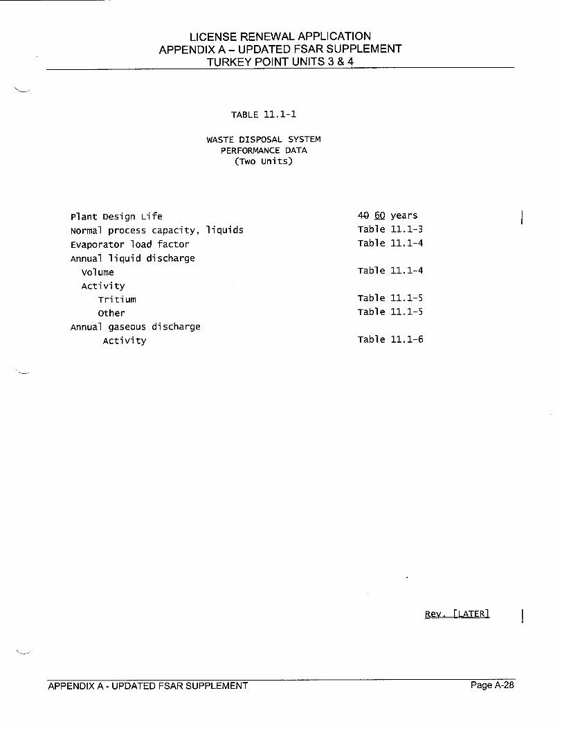
TABLE 11.1-1
WASTE DISPOSAL SYSTEM PERFORMANCE DATA
(Two units)
Plant Design Life Normal process capacity, liquids
Evaporator load factor
Annual liquid discharge volume Activity
Tritium other
Annual gaseous discharge Activity
4Tabl
Table Tabl e
years 11.1-3
11.1-4
Table 11.1-4
Table Table
11.1-5 11.1-5
Table 11.1-6
APPENDIX A - UPDATED FSAR SUPPLEMENT Page A-28Page A-28APPENDIX A - UPDATED FSAR SUPPLEMENT
LICENSE RENEWAL APPLICATION APPENDIX A - UPDATED FSAR SUPPLEMENT
TURKEY POINT UNITS 3 & 4
UFSAR CHAPTER 14.0 CHANGES
APPENDIX A - UPDATED FSAR SUPPLEMENT Page A-29Page A-29APPENDIX A - UPDATED FSAR SUPPLEMENT
LICENSE RENEWAL APPLICATION APPENDIX A - UPDATED FSAR SUPPLEMENT
TURKEY POINT UNITS 3 & 4
The neutron absorber rack design includes a poison verification viewhole in the cell wall so that the presence of poison material may be visually confirmed at any time over the life of the racks. upon completion of rack fabrication, such an inspection was performed. This visual inspection, coupled with the westinghouse quality assurance program controls and the use of qualified Boraflex neutron absorbing material, satisfies an initial verification test to assure that the proper quantity and placement of material was achieved during fabrication of the racks. This precludes the necessity for on-site poison verification.
As discussed in Section 4.7.2, irradiation tests have been previously erformed to test the stability and structural integrity of Boraflex in oric acid solution under irradiation[7]. These tests have concluded
that there is no evidence of deterioration of the suitability of the Boraflex poison material through a cumulative irradiation in excess of 1 x 10¹¹ rads gamma radiation. As more data on the service life performance of Boraflex becomes available in the nuclear industry in the coming years through both experimentation and operating experience, FPL will evaluate this information and will take action accordingly. L Subsection 16.2.2 for a program descriotion relating to License Renewal.
14D-56
APPENDIX A - UPDATED FSAR SUPPLEMENT Page A-iU
Rev. 3 -2----1--/96
Page A-30APPENDIX A - UPDATED FSAR SUPPLEMENT

LICENSE RENEWAL APPLICATION APPENDIX A - UPDATED FSAR SUPPLEMENT
TURKEY POINT UNITS 3 & 4
UFSAR[NEW] CHAPTER 16.0
APPENDIX A - UPDATED FSAR SUPPLEMENT Page A-31Page A-31APPENDIX A - UPDATED FSAR SUPPLEMENT
LICENSE RENEWAL APPLICATION APPENDIX A - UPDATED FSAR SUPPLEMENT
TURKEY POINT UNITS 3 & 4
MNEW CHAPTER 161
16.0 AGING MANAGEMENT PROGRAMS AND TIME-LIMITED
AGING ANALYSES ACTIVITIES
The integrated plant assessment for license renewal identified existing and new
aging management programs necessary to provide reasonable assurance that
components within the scope of license renewal will continue to perform their
intended functions consistent with the current licensing basis (CLB) for the period
of extended operation. This chapter describes these programs and their planned
implementation.
This chapter also discusses the evaluation results for each of the plant-specific time
limited aging analyses performed for license renewal. The evaluations have
demonstrated that the analyses remain valid for the period of extended operation;
the analyses have been projected to the end of the period of extended operation; or
that the effects of aging on the intended function(s) will be adequately managed for
the period of extended operation.
No 10 CFR 50.12 exemptions involving a time-limited aging analysis as defined in
10 CFR 54.3 were identified for Turkey Point.
16.1 NEW PROGRAMS
16.1.1 AUXILIARY FEEDWATER PUMP OIL COOLERS INSPECTION
The cast iron parts of the auxiliary feedwater pumps lube oil coolers and turbine
governor controller oil coolers, which are wetted internally by auxiliary feedwater, are
potentially susceptible to graphitic corrosion (i.e., selective leaching) and other types
of corrosion. A one-time visual inspection will be performed on one of the cast iron
bonnets of the auxiliary feedwater pump lube oil coolers to assess the extent of loss
of material due to corrosion. The results of this inspection will be evaluated to
determine the need for additional inspections/programmatic corrective actions. This
inspection and evaluation will be implemented prior to the end of the initial operating
license terms for Turkey Point Units 3 and 4.
APPENDIX A - UPDATED FSAR SUPPLEMENT Page A-32Page A-32APPENDIX A -UPDATED FSAR SUPPLEMENT
LICENSE RENEWAL APPLICATION APPENDIX A - UPDATED FSAR SUPPLEMENT
TURKEY POINT UNITS 3 & 4
16.1.2 AUXILIARY FEEDWATER STEAM PIPING INSPECTION PROGRAM
The Auxiliary Feedwater Steam Piping Inspection Program manages the aging
effects of loss of material due to general and pitting corrosion on the internal and
external surfaces of carbon steel auxiliary feedwater steam supply lines. Periodic
volumetric examinations of representative auxiliary feedwater steam supply
components will be performed to ensure that minimum required wall thickness is
maintained. Examinations will be performed on piping/fittings and other components
using volumetric techniques, such as ultrasonic or computed radiography. The
inspections will be implemented prior to the end of the initial operating license terms for Turkey Point Units 3 and 4.
16.1.3 EMERGENCY CONTAINMENT COOLERS INSPECTION
A one-time volumetric examination of a sample of emergency containment coolers
(ECC) tubes will be performed to determine the extent of loss of materi'at-due to
erosion in the ECC tubes. The results of this inspection will be evaluated to
determine the need for additional inspections/programmatic corrective actions. This
inspection and evaluation will be implemented prior to the end of the initial operating
license terms for Turkey Point Units 3 and 4.
16.1.4 FIELD ERECTED TANKS INTERNAL INSPECTION
A one-time visual inspection to determine the extent of corrosion on the internal
surfaces of the field erected tanks for both units -- including the Condensate Storage
Tanks, the Demineralized Water Storage Tank, and the Refueling Water Storage
Tanks -- will be performed. The results of these inspections will be evaluated to
determine the need for additional inspections/programmatic corrective actions.
These inspections will be implemented prior to the end of the initial operating license
terms for Turkey Point Units 3 and 4.
16.1.5 GALVANIC CORROSION SUSCEPTIBILITY INSPECTION PROGRAM
The Galvanic Corrosion Susceptibility Inspection Program manages the aging effect
of loss of material due to galvanic corrosion on the internal surfaces of susceptible
piping and components. The program involves selected, one-time inspections on
the internal surfaces-0f piping and components with the greatest susceptibility to
galvanic corrosion. Loss of material is expected mainly in carbon steel components
directly coupled to stainless steel components in raw water systems, however,
baseline examinations in select systems will be performed and evaluated to
APPENDIX A - UPDATED FSAR SUPPLEMENT rage A-33

LICENSE RENEWAL APPLICATION APPENDIX A - UPDATED FSAR SUPPLEMENT
TURKEY POINT UNITS 3 & 4
establish if the corrosion mechanism is active. Based on the results of these
inspections, the need for followup examinations or programmatic corrective actions
will be established. The program will be implemented prior to the end of the initial
operating license terms for Turkey Point Units 3 and 4.
16.1.6 REACTOR VESSEL INTERNALS INSPECTION PROGRAM
The Reactor Vessel Internals Inspection Program consists of two types of
examinations, visual and ultrasonic testing. The visual examination manages the
aging effect of cracking due to irradiation assisted stress corrosion (IASCC) and
reduction in fracture toughness due to irradiation and thermal embrittlement. The
ultrasonic testing examination manages the aging effect of loss of mechanical
closure integrity of reactor vessel internals bolting. The program, including an
evaluation of program scope with regard to dimensional changes due to void swelling, will be in place prior to the end of the initial operating license terms for
Turkey Point Units 3 and 4, and the actual visual and ultrasonic examinations, one
inspection per unit, will be performed during the period of extended operation.
16.1.7 SMALL BORE CLASS I PIPING INSPECTION
A volumetric inspection of a sample of small bore Class 1 piping and nozzles will be
performed to determine if cracking is an aging effect requiring management during
the period of extended operation. This one-time inspection will address Class 1
piping less than 4 inches in diameter. Based on the results of these inspections, the need for additional inspections or programmatic corrective actions will be established. The inspection will be performed prior to the end of the initial operating license terms for Turkey Point Units 3 and 4.
16.2 EXISTING PROGRAMS
16.2.1 ASME SECTION XI INSERVICE INSPECTION PROGRAMS
16.2.1.1 ASME SECTION XI, SUBSECTIONS IWB, IWC, AND IWD INSERVICE INSPECTION PROGRAM
ASME Section XI, Subsections IWB, IWC, and IWD Inservice Inspection Program
inspections identify and correct degradation in Class 1, 2, and 3 components and
piping. The program manages the aging effects of loss of material, cracking, and
loss of mechanical closure integrity. The program provides inspection and
APPENDIX A - UPDATED FSAR SUPPLEMENT Page A-34
LICENSE RENEWAL APPLICATION APPENDIX A - UPDATED FSAR SUPPLEMENT
TURKEY POINT UNITS 3 & 4
examination of accessible components, including welds, pump casings, valve
bodies, steam generator tubing, and pressure-retaining bolting.
16.2.1.2 ASME SECTION XI, SUBSECTION IWE INSERVICE INSPECTION PROGRAM
ASME Section Xl, Subsection IWE Inservice Inspection Program inspections identify
and correct degradation of pressure retaining components and their integral
attachments and the metallic liner of Class CC pressure-retaining components and
their integral attachments. The program manages the aging effects of loss of
material and loss of pressure retention. The program provides inspection and
examination of containment surfaces, seals, gaskets and moisture barriers,
pressure-retaining bolting, and pressure retaining components in accordance with
the requirements of ASME Section XI, Subsection IWE.
16.2.1.3 ASME SECTION XI, SUBSECTION IWF INSERVICE INSPECTION PROGRAM
ASME Section XI, Subsection IWF Inservice Inspection Program inspections identify
and correct degradation of ASME Class 1, 2, and 3 component supports. This
program manages the aging effect of loss of material. The scope of the program
provides for inspection and examination of accessible surface areas of the
component supports in accordance with the requirements of ASME Section XI,
Subsection IWF.
16.2.1.4 ASME SECTION XI, SUBSECTION IWL INSERVICE INSPECTION PROGRAM
ASME Section XI, Subsection IWL Inservice Inspection Program inspections assess
the quality and structural performance of the Containment structure post-tensioning
system components. The program manages the aging effects of loss of material
and confirms the results of the Containment tendon loss of prestress Time-Limited
Aging Analysis (see Subsection 16.3.4). The program includes inspection of tendon
and anchorage hardware surfaces and measurement of tendon force and
elongation.
16.2.2 BORAFLEX SURVEILLANCE PROGRAM
The Boraflex Surveillance Program manages the aging effect of change in material
properties for the Boraflex material in the spent fuel storage racks.
The program will be enhanced to provide for density testing (or other approved
testing methods if available) of the encapsulated Boraflex material in the spent fuel
Page A-35APPENDIX A - UPDATED FSAR SUPPLEMENT

LICENSE RENEWAL APPLICATION APPENDIX A - UPDATED FSAR SUPPLEMENT
TURKEY POINT UNITS 3 & 4
storage racks prior to the end of the initial operating license terms for Turkey Point
Units 3 and 4.
16.2.3 BORIC ACID WASTAGE SURVEILLANCE PROGRAM
The Boric Acid Wastage Surveillance Program manages the aging effects of loss of
material and mechanical closure integrity due to aggressive chemical attack
resulting from borated water leaks. The program addresses the Reactor Coolant
System and structures and components containing, or exposed to, borated water.
This program utilizes systematic inspections, leakage evaluations, and corrective
actions to ensure that boric acid corrosion does not lead to degradation of pressure boundary or structural integrity of components, supports, or structures, including
electrical equipment in proximity to borated water systems. This program includes
commitments to NRC Generic Letter 88-05, "Boric Acid Corrosion of Carbon Steel
Reactor Pressure Boundary Components in PWR Plants."
Some systems outside Containment (i.e., Spent Fuel Pool Cooling and portions of
Waste Disposal associated with containment integrity) are currently inspected under
other existing programs. The scope of the Boric Acid Wastage Surveillance
Program will be enhanced to include these systems and components prior to the end
of the initial operating license terms for Turkey Point Units 3 and 4.
16.2.4 CHEMISTRY CONTROL PROGRAM
The Chemistry Control Program manages loss of material, cracking, and fouling
aging effects for primary and secondary systems, structures, and components. The aging effects are minimized or prevented by controlling the chemical species that
cause the underlying mechanism(s) that results in these aging effects. Alternatively,
chemical agents, such as corrosion inhibitors and biocides, are introduced to prevent
certain aging mechanisms. The program includes sampling activities and analysis.
The program provides assurance that an elevated level of contaminants and oxygen
does not exist in the systems, structures, and components covered by the program, and thus prevents and minimizes the occurrences of aging effects.
16.2.5 CONTAINMENT SPRAY SYSTEM PIPING INSPECTION PROGRAM
The Containment Spray System Piping Inspection Program manages the aging
effect loss of material due to general, crevice, and pitting corrosion on the internal
surfaces of carbon steel piping and fittings, and valves wetted by boric acid in the
Containment Spray System spray headers. Periodic ultrasonic examinations of
APPENDIX A - UPDATED FSAR SUPPLEMENT Page A-36

LICENSE RENEWAL APPLICATION APPENDIX A - UPDATED FSAR SUPPLEMENT
TURKEY POINT UNITS 3 & 4
selected locations are used to determine wall thickness and are evaluated to ensure
that minimum thickness requirements are maintained.
16.2.6 ENVIRONMENTAL QUALIFICATION PROGRAM
The Environmental Qualification Program evaluations of electrical equipment are
identified as Time-Limited Aging Analyses. Equipment covered by the
Environmental Qualification Program has been evaluated to determine if the existing
Environmental Qualification aging analyses can be projected to the end of the period
of extended operation by reanalysis or additional analysis. Qualification into the
license renewal period is treated the same as equipment initially qualified for 40
years or less. When analysis cannot justify a qualified life in excess of the license
renewal period, then the component parts will be replaced, refurbished, or
requalified prior to exceeding the qualified life in accordance with the Environmental
Qualification Program.
16.2.7 FATIGUE MONITORING PROGRAM
The Fatigue Monitoring Program is designed to track design cycles to ensure that
Reactor Coolant System components remain within their design fatigue limits.
Design cycle limits for Turkey Point Units 3 and 4 are provided in Table 4.1-8. The
specific fatigue analyses validated by the Fatigue Monitoring Program are
associated with the reactor vessels, reactor vessel internals, pressurizers, steam
generators, reactor coolant pumps, and pressurizer surge lines. Administrative
procedures provide the methodology for logging design cycles. Guidance is provided in the event design cycle limits are approached.
16.2.8 FIRE PROTECTION PROGRAM
The Fire Protection Program manages the aging effects of loss of material, cracking,
and fouling for the components/piping of the Fire Protection System and Fire Rated
Assemblies. Additionally, this program manages the aging effects of loss of
material, loss of seal, cracking, and erosion for structures and structural components
associated with fire protection. Appendix 9.6A contains a detailed discussion of the Fire Protection Program.
The scope of the Fire Protection Program will be enhanced to include inspection of
additional components prior to the end of the initial operating license terms for Turkey Point Units 3 and 4.
Page A-37APPENDIX A - UPDATED FSAR SUPPLEMENT
LICENSE RENEWAL APPLICATION APPENDIX A - UPDATED FSAR SUPPLEMENT
TURKEY POINT UNITS 3 & 4
"16.2.9 FLOW ACCELERATED CORROSION PROGRAM
The Flow Accelerated Corrosion Program manages the aging effect of loss of material due to flow accelerated corrosion. The Flow Accelerated Corrosion Program predicts, detects, monitors, and mitigates flow accelerated corrosion wear
in high energy carbon steel piping associated with the Main Steam and Turbine Generators, and Feedwater and Blowdown Systems, and is based on industry guidelines and experience. The program includes analysis and baseline inspections; determination, evaluation, and corrective actions for affected components; and follow-up inspections.
This program will be enhanced to address internal and external loss of material of steam trap lines due to flow accelerated corrosion and general corrosion, respectively, prior to the end of the initial operating license terms for Turkey Point
Units 3 and 4.
16.2.10 INTAKE COOLING WATER SYSTEM INSPECTION PROGRAM
The Intake Cooling Water System Inspection Program manages the aging effects of
_ loss of material due to various corrosion mechanisms, stress corrosion cracking, and biological fouling for Intake Cooling Water System components. The program includes inspections, performance testing, evaluations, and corrective actions that are performed as the result of FPL commitments to NRC Generic Letter 89-13, "Service Water System Problems Affecting Safety-Related Equipment."
This program will be enhanced to improve documentation of scope and frequency of the intake cooling water piping crawl-through inspections and component cooling water heat exchanger tube integrity inspections prior to the end of the initial operating license terms for Turkey Point Units 3 and 4.
16.2.11 PERIODIC SURVEILLANCE AND PREVENTIVE MAINTENANCE PROGRAM
The Periodic Surveillance and Preventive Maintenance Program manages the aging effects of loss of material, cracking, fouling buildup, loss of seal, and embrittlement for systems, structures, and components. The scope of the program provides for visual inspection and examination of selected surfaces of specific components and structural components. The program also includes leak inspection of limited portions of the Chemical and Volume Control Systems. Additionally, the program provides
APPENDIX A - UPDATED FSAR SUPPLEMENT Page A-38

LICENSE RENEWAL APPLICATION APPENDIX A - UPDATED FSAR SUPPLEMENT
TURKEY POINT UNITS 3 & 4
for replacement/refurbishment of selected components on a specified frequency, as
appropriate.
Specific enhancements to the scope and documentation of some inspections
performed under this program will be implemented prior to the end of the initial
operating license terms for Turkey Point Units 3 and 4.
16.2.12 REACTOR VESSEL HEAD ALLOY 600 PENETRATION INSPECTION
PROGRAM
The Reactor Vessel Head Alloy 600 Penetration Inspection Program encompasses
the Turkey Point Units 3 and 4 reactor vessel head Alloy 600 penetrations that are
part of the Reactor Coolant System pressure boundary. This program manages the
aging effect of cracking due to primary water stress corrosion (PWSCC). The
program includes a one-time volumetric examination of selected Unit 4 reactor
vessel head penetrations to detect crack initiation. Visual examination of the Unit 3
and Unit 4 reactor vessel head external surfaces during outages and the Boric Acid
Wastage Surveillance Program are also utilized to manage cracking.
16.2.13 REACTOR VESSEL INTEGRITY PROGRAM
The Reactor Vessel Integrity Program manages reactor vessel irradiation
embrittlement and encompasses the following subprograms:
"* Reactor Vessel Surveillance Capsule Removal and Evaluation
"* Fluence and Uncertainty Calculations
"* Monitoring Effective Full Power Years
"* Pressure-Temperature Limit Curves
Program documentation will be enhanced to integrate all aspects of the Reactor
Vessel Integrity Program prior to the end of the initial operating license terms for
Turkey Point Units 3 and 4.
16.2.13.1 REACTOR VESSEL SURVEILLANCE CAPSULE REMOVAL AND EVALUATION
This subprogram manages the aging effect of reduction in fracture toughness of the
Turkey Point Units 3 and 4 reactor vessel materials (beltline forgings and
circumferential welds) due to neutron irradiation embrittlement by performing Charpy
V-notch and tensile tests on the reactor vessel irradiated specimens. The Reactor
Vessel Surveillance Capsule Removal and Evaluation subprogram is a
APPENDIX A - UPDATED FSAR SUPPLEMENT Page A-39
LICENSE RENEWAL APPLICATION APPENDIX A - UPDATED FSAR SUPPLEMENT
TURKEY POINT UNITS 3 & 4
NRC-approved program that meets the requirements of 10 CFR 50, Appendix H.
The surveillance capsule withdrawal schedule is specified in Table 4.4-2.
16.2.13.2 FLUENCE AND UNCERTAINTY CALCULATIONS
This subprogram provides an accurate prediction of the Turkey Point Units 3 and 4
reactor vessel accumulated fast neutron fluence values at the reactor vessel beltline
forgings and circumferential welds.
16.2.13.3 MONITORING EFFECTIVE FULL POWER YEARS
This subprogram accurately monitors and tabulates the accumulated operating time
experienced by the reactor vessels to ensure that the Turkey Point Units 3 and 4
pressure-temperature limit curves and end-of-life reference temperatures are not
exceeded.
16.2.13.4 PRESSURE-TEMPERATURE LIMIT CURVES
This subprogram provides pressure-temperature limit curves for the Turkey Point
Units 3 and 4 reactor vessels to establish the Reactor Coolant System operating
limits. The pressure-temperature limit curves are included in the Technical
Specifications.
16.2.14 STEAM GENERATOR INTEGRITY PROGRAM
The Steam Generator Integrity Program ensures steam generator integrity is
maintained under normal operating, transient, and postulated accident conditions.
The program manages the aging effects of cracking and loss of material and
includes the following essential elements:
"* Inspection of steam generator tubing and tube plugs
"* Steam generator secondary-side integrity inspections
"• Tube integrity assessments
"* Assessment of degradation mechanisms
"* Primary-to-secondary leakage monitoring
"* Primary and secondary chemistry control
"* Sludge lancing
"* Maintenance and repairs
Page A-40APPENDIX A -UPDATED FSAR SUPPLEMENT
LICENSE RENEWAL APPLICATION APPENDIX A - UPDATED FSAR SUPPLEMENT
TURKEY POINT UNITS 3 & 4
Foreign material exclusion
16.2.15 SYSTEMS AND STRUCTURES MONITORING PROGRAM
The Systems and Structures Monitoring Program manages the aging effects of loss
of material, cracking, fouling, loss of seal, and change in material properties. The
program provides for periodic visual inspection and examination for degradation of
accessible surfaces of specific systems, structures, and components, and corrective
actions as required based on these inspections.
This program will be enhanced by restructuring it to address inspection requirements
to manage certain aging effects in accordance with 10 CFR 54, modifying the scope
of specific inspections, and improving documentation requirements prior to the end
of the initial operating license terms for Turkey Point Units 3 and 4.
16.2.16 THIMBLE TUBE INSPECTION PROGRAM
The Thimble Tube Inspection Program manages the aging effect of material loss
due to fretting wear. This program consists of an eddy current test inspection of
thimble tube N-05 on Unit 3. Eddy current testing of thimble tubes was initiated in
response to NRC Bulletin 88-09, "Thimble Tube Thinning in Westinghouse
Reactors," and inspections have been performed on all in-service thimble tubes for
Units 3 and 4. This inspection will be performed prior to the end of the initial
operating license term for Turkey Point Unit 3.
APPENDIX A - UPDATED FSAR SUPPLEMENT Page A-41
LICENSE RENEWAL APPLICATION APPENDIX A - UPDATED FSAR SUPPLEMENT
TURKEY POINT UNITS 3 & 4
16.3 TIME-LIMITED AGING ANALYSIS ACTIVITIES
16.3.1 REACTOR VESSEL IRRADIATION EMBRITTLEMENT
The Turkey Point Units 3 and 4 reactor vessels are described in Chapters 3.0 and
4.0. Time-limited aging analyses (TLAAs) applicable to the reactor vessels are:
"* pressurized thermal shock
"* upper-shelf energy
"* pressure-temperature limits
The Reactor Vessel Integrity Program, described in Subsection 16.2.13, manages
reactor vessel irradiation embrittlement utilizing subprograms to monitor, calculate,
and evaluate the time-dependent parameters used in the aging analyses for
pressurized thermal shock, Charpy upper-shelf energy, and pressure-temperature
limit curves to ensure continuing vessel integrity through the period of extended
operation.
16.3.1.1 PRESSURIZED THERMAL SHOCK
The requirements in 10 CFR 50.61 provide rules for protection against pressurized
thermal shock events for pressurized water reactors. Licensees are required to
perform an assessment of the projected values of the maximum nil ductility
reference temperature (RTpTs) whenever a significant change occurs in projected
values of RTPTS, or upon request for a change in the expiration date for the operation
of the facility.
The calculated RTPTS values at the end of the extended period of operation
(48 effective full power years) for the Turkey Point Units 3 and 4 reactor vessels are
less than the 10 CFR 50.61 (b)(2) screening criteria of 270o F for intermediate and
lower shells and 3000F for the circumferential welds. Based upon the revised
calculations, additional measures will not be required for the Turkey Point reactor
vessels during the license renewal period.
The analysis associated with pressurized thermal shock has been projected to the
end of the period of extended operation, in accordance with the requirements of
10 CFR 54.21(c)(1)(ii).
I-�1ye M'tLAPPENDIX A - UPDATED FSAR SUPPLEMENT rage A-12

LICENSE RENEWAL APPLICATION APPENDIX A - UPDATED FSAR SUPPLEMENT
TURKEY POINT UNITS 3 & 4
16.3.1.2 UPPER-SHELF ENERGY
The requirements on reactor vessel Charpy upper-shelf energy are included in
10 CFR 50, Appendix G. Specifically, 10 CFR 50, Appendix G requires licensees to
submit an analysis at least 3 years prior to the time that the upper-shelf energy of
any reactor vessel material is predicted to drop below 50 ft-lb., as measured by
Charpy V-notch specimen testing.
A fracture mechanics evaluation was performed in accordance with Appendix K of
ASME Section XI to demonstrate continued acceptable equivalent margins of safety
against fracture through 48 effective full power years.
The analysis associated with upper-shelf energy has been projected to the end of
the period of extended operation in accordance with the requirements of 10 CFR
54.21 (c)(1)(ii).
16.3.1.3 PRESSURE-TEMPERATURE LIMITS
The requirements in 10 CFR 50, Appendix G, ensure that heatup and cooldown of
the reactor pressure vessel are accomplished within established pressure
temperature limits. These limits specify the maximum allowable pressure as a
function of reactor coolant temperature. As the reactor pressure vessel becomes
embrittled and its fracture toughness is reduced, the allowable pressure is reduced.
Operation of the Reactor Coolant System is also limited by the net positive suction
curves for the reactor coolant pumps. These curves specify the minimum pressure
required to operate the reactor coolant pumps. Therefore, in order to heatup and
cooldown, the reactor coolant temperature and pressure must be maintained within
an operating window established between the Appendix G pressure-temperature
limits and the net positive suction curves.
To address the period of extended operation, the 48 effective full power year
projected fluences and the Turkey Point-specific reactor vessel material properties
were used to determine the limiting material and calculate pressure-temperature
limits for heatup and cooldown. The limiting material at all temperatures for the
period of extended operation is the circumferential girth weld.
A license amendment to incorporate the pressure-temperature limit curves projected
to 48 effective full power years will be submitted to the NRC for review and approval
prior to exceeding the licensed operating period for these curves.
APPENDIX A - UPDATED FSAR SUPPLEMENT Page A-43

LICENSE RENEWAL APPLICATION APPENDIX A - UPDATED FSAR SUPPLEMENT
TURKEY POINT UNITS 3 & 4
The analysis associated with reactor vessel pressure-temperature limit curves has
been projected to the end of the period of extended operation, in accordance with 10
CFR 54.21(c)(1)(ii).
16.3.2 METAL FATIGUE
The thermal and mechanical fatigue analyses of plant mechanical components have
been identified as time-limited aging analyses for Turkey Point. Specific
components have been designed considering transient cycle assumptions, as listed
in vendor specifications and the Turkey Point UFSAR.
16.3.2.1 ASME BOILER AND PRESSURE VESSEL CODE, SECTION III, CLASS 1
COMPONENTS
The reactor vessels, reactor vessel internals, pressurizers, steam generators,
reactor coolant pumps, and pressurizer surge lines have been designed in
accordance with the requirements of the ASME Boiler and Pressure Vessel Code,
Section III, Class 1. The ASME Boiler and Pressure Vessel Code, Section III,
Class 1 requires a design analysis to address fatigue and establish limits such that
initiation of fatigue cracks is precluded.
Fatigue usage factors for critical locations in the Turkey Point Units 3 and 4 Nuclear
Steam Supply System components were determined using design cycles that were
specified in the plant design process. These design cycles were intended to be
conservative and bounding for all foreseeable plant operational conditions. The
design cycles were subsequently utilized in the design stress reports for various
Nuclear Steam Supply System components satisfying ASME fatigue usage design
requirements, and became part of the plant Technical Specifications.
Experience has shown that actual plant operation is often very conservatively
represented by these design cycles. The use of actual operating history data allows
the quantification of these conservatisms in the existing fatigue analyses. To
demonstrate that the Class 1 component fatigue analyses remain valid for the period
of extended operation, the design cycle set applicable to the Class 1 components
was assembled. The actual frequency of occurrence for the design cycles was
determined and compared to the design cycle set. The severity of the actual plant
transients was compared to the severity of the design cycles. This comparison was
performed in order to demonstrate that on an event-by-event basis, the design cycle
profiles envelop actual plant operation. In addition, a review of the applicable
Page A-44APPENDIX A -UPDATED FSAR SUPPLEMENT

LICENSE RENEWAL APPLICATION APPENDIX A - UPDATED FSAR SUPPLEMENT
TURKEY POINT UNITS 3 & 4
administrative and operating procedures was performed to verify the effectiveness of
the current design cycle counting program.
This review concluded that the existing design cycles and cycle frequencies are
conservative and bounding for the period of extended operation.
The analyses associated with verifying the structural integrity of the reactor vessels,
reactor vessel internals, pressurizers, steam generators, reactor coolant pumps, and
pressurizer surge lines have been evaluated and determined to remain valid for the
period of extended operation, in accordance with 10 CFR 54.21(c)(1)(i).
As a confirmatory program, the monitoring of plant transients performed as a part of
the Fatigue Monitoring Program, as described in Subsection 16.2.7, will assure that
the design cycle limits are not exceeded.
16.3.2.2 REACTOR VESSEL UNDERCLAD CRACKING
In early 1971, an anomaly identified as grain boundary separation, perpendicular to
the direction of the cladding weld overlay, was identified in the heat-affected zone of
reactor vessel base metal. A generic fracture mechanics evaluation demonstrated
that the growth of underclad cracks during a 40-year plant life is insignificant.
The evaluation was extended to 60 years using fracture mechanics evaluations
based on a representative set of design transients with the occurrences extrapolated
to cover 60 years of service life. The 60-year evaluation shows insignificant growth
of the underclad cracks.
The analysis associated with reactor vessel underclad crack growth has been
projected to the end of the period of extended operation, in accordance with
10 CFR 54.21 (c)(1)(ii).
16.3.2.3 REACTOR COOLANT PUMP FLYWHEEL
During normal operation, the reactor coolant pump flywheel possesses sufficient
kinetic energy to potentially produce high-energy missiles in the unlikely event of
failure. Conditions which may result in overspeed of the reactor coolant pump
increase both the potential for failure and the kinetic energy. The aging effect of
concern is fatigue crack initiation in the flywheel bore keyway. An evaluation of the
probability of failure over the extended period of operation was performed. It
demonstrates that the flywheel design has a high structural reliability with a very high
flaw tolerance and negligible flaw crack extension over a 60-year service life.
Page A-45APPENDIX A -UPDATED FSAR SUPPLEMENT

LICENSE RENEWAL APPLICATION APPENDIX A - UPDATED FSAR SUPPLEMENT
TURKEY POINT UNITS 3 & 4
The analysis associated with the structural integrity of the reactor coolant pump
flywheel has been evaluated and determined to remain valid for the period of
extended operation, in accordance with 10 CFR 54.21 (c)(1)(i).
16.3.2.4 ANSI B31.1 PIPING
The Reactor Coolant System primary loop piping and balance-of-plant piping are
designed to the requirements of ANSI B31.1, Power Piping. The exceptions are the
Units 3 and 4 pressurizer surge lines and the Unit 4 Emergency Diesel Generator
safety-related piping.
The pressurizer surge lines have been designed to the requirements of ASME Boiler
and Pressure Vessel Code, Section III, Class 1.
The Unit 4 Emergency Diesel Generator safety-related piping has been designed to
the requirements of ASME Boiler and Pressure Vessel Code, Section III, Class 3,
which is essentially the same as ANSI B31.1 design requirements. The evaluation
of the Unit 4 Emergency Diesel Generator safety-related piping fatigue is, therefore,
included in the discussion below.
Design requirements in ANSI B31.1 assume a stress range reduction factor to
provide conservatism in the piping design to account for fatigue due to thermal cyclic
operation. This reduction factor is 1.0 provided the number of anticipated cycles is
limited to 7000 equivalent full temperature cycles. This represents a condition where
a piping system would have to be cycled approximately once every 3 days over the
extended plant life of 60 years. Considering this limit, a review of the ANSI B31.1
piping within the scope of license renewal was performed in order to identify those
systems that operate at elevated temperature and to establish their cyclic operating
practices. Under current plant operating practices, piping systems within the scope of
license renewal are only occasionally subject to cyclic operation. Typically these
systems are subject to continuous steady-state operation and vary operating
temperatures only during plant heatup and cooldown, during plant transients, or during
periodic testing. The results of the evaluation for ANSI B31.1 piping systems
demonstrate that the number of assumed thermal cycles would not be exceeded in 60
years of plant operation.
The analyses associated with ANSI B31.1 piping fatigue have been evaluated and
determined to remain valid for the period of extended operation, in accordance with
10 CFR 54.21 (c)(1 )(i).
Page A-46APPENDIX A - UPDATED FSAR SUPPLEMENT

LICENSE RENEWAL APPLICATION APPENDIX A - UPDATED FSAR SUPPLEMENT
TURKEY POINT UNITS 3 & 4
16.3.2.5 ENVIRONMENTALLY ASSISTED FATIGUE
The Turkey Point approach to address reactor water environmental effects
accomplishes two objectives. First, the TLAA on fatigue design has been resolved
by confirming that the original transient design limits remain valid for the 60-year
operating period. Confirmation by fatigue monitoring will ensure these transient
design limits are not exceeded. Second, reactor water environmental effects on
fatigue life are examined using the most recent data from laboratory simulation of
the reactor coolant environment.
As a part of the industry effort to address environmental effects for operating nuclear
power plants during the current 40-year licensing term, Idaho National Engineering
Laboratories (INEL) evaluated, in NUREG/CR-6260, "Application of NUREG/CR
5999 Interim Fatigue Curves to Selected Nuclear Power Plant Components,"
March 1995, fatigue-sensitive component locations at plants designed by all four
U. S. Nuclear Steam Supply System (NSSS) vendors. The pressurized water
reactor (PWR) calculations, especially the early-vintage Westinghouse PWR
calculations, are directly relevant to Turkey Point. The description of the "Older
Vintage Westinghouse Plant" evaluated in NUREG/CR-6260 matches Turkey Point
with respect to design code. In addition, the transient cycles considered in the
evaluation match or bound Turkey Point design.
NUREG/CR-6260 calculated fatigue usage factors for critical fatigue-sensitive
component locations for the early-vintage Westinghouse plant utilizing the interim
fatigue curves provided in NUREG/CR-5999, "Interim Fatigue Design Curves for
Carbon, Low-Alloy, and Austenitic Stainless Steels in LWR Environments,"
August 1993. The results of NUREG/CR-6260 analyses were then utilized to scale
up the Turkey Point plant-specific usage factors for the same locations to account for
environmental effects. Generic industry studies performed by EPRI and NEI were
also considered in this aspect of the evaluation, as well as environmental data that
have been collected and published subsequent to the generic industry studies.
Based on these adjustments, only the pressurizer surge line piping required further
evaluation for the period of extended operation.
In lieu of additional analyses to refine the usage factor for the pressurizer surge
lines, Turkey Point has selected aging management to address pressurizer surge
line fatigue during the period of extended operation. In particular, the potential for
crack initiation and growth, including reactor water environmental effects, will be
managed by the Turkey Point ASME Section XI, Subsections IWB, IWC, and IWD
Inservice Inspection Program, as described in Subsection 16.2.1.1.
APPENDIX A - UPDATED FSAR SUPPLEMENT Page A-47
LICENSE RENEWAL APPLICATION APPENDIX A - UPDATED FSAR SUPPLEMENT
TURKEY POINT UNITS 3 & 4
16.3.3 ENVIRONMENTAL QUALIFICATION
The thermal, radiation, and wear cycle aging analyses of plant electrical and I&C
components have been identified as time-limited aging analyses for Turkey Point.
In particular, the environmental qualification evaluations of electrical equipment with
a 40-year qualified life or greater have been determined to be time-limited aging
analyses.
Equipment included in the Turkey Point Environmental Qualification Program has been evaluated to determine if existing environmental qualification aging analyses
can be projected to the end of the period of extended operation by reanalysis or
additional analysis. Qualification into the license renewal period is treated the same
as for equipment currently qualified at Turkey Point for 40 years or less. When
aging analysis cannot justify a qualified life into the license renewal period, then the
component or parts will be replaced prior to exceeding their qualified lives in
accordance with the Environmental Qualification Program, as described in
Subsection 16.2.6.
Age-related service conditions that are applicable to the environmentally qualified
equipment (i.e., 60 years of exposure versus 40 years) were evaluated for the period
of extended operation to verify that the current environmental qualification analyses
are bounding. The evaluations considered radiation, thermal, and wear cycle aging
effects.
Therefore, the analyses associated with the environmental qualification of electrical
equipment remain valid for the period of extended operation, in accordance with the
requirements of 10 CFR 54.21 (c)(1)(i), or have been projected to the end of the
period of extended operation, in accordance with the requirements of
10 CFR 54.21(c)(1)(ii).
16.3.4 CONTAINMENT TENDON LOSS OF PRESTRESS
The Turkey Point Units 3 and 4 containment buildings are post-tensioned, reinforced
concrete structures composed of vertical cylinder walls and a shallow dome,
supported on a conventional reinforced concrete base slab. The cylinder walls are
provided with vertical tendons and horizontal hoop tendons. The dome is provided
with three groups of tendons oriented 120-degrees apart.
The prestress of containment tendons decreases over time as a result of seating of
anchorage losses, elastic shortening of concrete, creep of concrete, shrinkage of
APPENDIX A -UPDATED FSAR SUPPLEMENT Page A-48
LICENSE RENEWAL APPLICATION APPENDIX A - UPDATED FSAR SUPPLEMENT
TURKEY POINT UNITS 3 & 4
concrete, relaxation of prestressing steel, and friction losses. New upper limit curves,
lower limit curves, and trend lines of measured prestressing forces have been
established for all tendons through the period of extended operation. The predicted
final effective preload at the end of 60 years exceeds the minimum required preload
for all containment tendons. Consequently, the post-tensioning system will continue
to perform its intended function throughout the period of extended operation.
The analyses associated with containment tendon loss of prestress have been
projected to the end of the period of extended operation, in accordance with the
requirements of 10 CFR 54.21 (c)(1)(ii).
As a confirmatory program, the Containment structure post-tensioning system
surveillance performed as a part of the ASME Section XI, Subsection IWL Inservice
Inspection Program, as described in Subsection 16.2.1.4, will continue to be
performed in accordance with the requirements of plant Technical Specifications.
16.3.5 CONTAINMENT LINER PLATE FATIGUE
The interior surface of each Containment is lined with welded steel plate to provide
an essentially leak-tight barrier. Design criteria are applied to the liner to assure that
the specified allowed leak rate is not exceeded under the design basis accident
conditions. The fatigue loads, as described in Appendix 5B, Section B.2.1, were
considered in the design of the liner plates and are considered time-limited aging
analyses for the purposes of license renewal. Each of these has been evaluated for
the period of extended operation.
The number of thermal cycles due to annual outdoor temperature variations was
increased from 40 to 60 for the extended period of operation. The effect of this
increase is insignificant in comparison to the assumed 500 thermal cycles due to
Containment interior temperature varying during heatup and cooldown of the
Reactor Coolant System. The 500 thermal cycles includes a margin of 300 thermal
cycles above the 200 Reactor Coolant System allowable design heatup and
cooldown cycles, which is sufficient margin to accommodate the additional 20 cycles
of annual outdoor temperature variation. Therefore, this loading condition is
considered valid for the period of extended operation as it is enveloped by the
evaluation for 500 thermal cycles.
The assumed 500 thermal cycles was evaluated based on the more limiting heatup
and cooldown design cycles (transients) for the Reactor Coolant System. The
Reactor Coolant System was designed to withstand 200 heatup and cooldown
APPENDIX A - UPDATED FSAR SUPPLEMENT Page A-49
LICENSE RENEWAL APPLICATION APPENDIX A - UPDATED FSAR SUPPLEMENT
TURKEY POINT UNITS 3 & 4
thermal cycles. The evaluation determined that the originally projected number of
maximum Reactor Coolant System design cycles is conservative enough to envelop
the projected cycles for the extended period of operation. Therefore, the original
containment liner plate fatigue analysis for 500 heatup and cooldown cycles is
considered valid for the period of extended operation.
The assumed value of one for thermal cycling due to the maximum hypothetical
accident remains valid. No maximum hypothetical accident has occurred and none
is expected, therefore, this assumption is considered valid for the period of extended
operation.
The design of the containment penetrations has been reviewed. The design meets
the general requirements of the 1965 Edition of ASME Boiler and Pressure Vessel
Code, Section III. The main steam piping, feedwater piping, blowdown piping, and
letdown piping are the only piping penetrating the containment wall and liner plate
that contribute significant thermal loading on the liner plate. The projected number
of actual operating cycles for these piping systems through 60 years of operation
was determined to be less than the original design limits.
The analyses associated with the containment liner plate and penetrations have
been evaluated and determined to remain valid for the period of extended operation,
in accordance with 10 CFR 54.21(c)(1)(i).
16.3.6 BOTTOM MOUNTED INSTRUMENTATION THIMBLE TUBE WEAR
As discussed in NRC Information Notice No. 87-44, Supplement 1, "Thimble Tube
Thinning in Westinghouse Reactors," thimble tubes have experienced thinning as a
result of flow-induced vibration. Thimble tube wear results in degradation of the
Reactor Coolant System pressure boundary and could potentially create a non
isolable leak of reactor coolant. Therefore, the NRC staff requested that licensees
perform the actions described in NRC Bulletin No. 88-09, "Thimble Tube Thinning in
Westinghouse Reactors." In response to this bulletin, FPL established a program for
inspection and assessment of thimble tube thinning. Turkey Point commitments to
the NRC for two eddy current inspections of the thimble tubes for each unit were
completed in May 1990 for Unit 4, and in December 1992 for Unit 3. The results
demonstrated that the thimble tubes were acceptable for operation and that no
appreciable thinning had occurred between the two inspections. Based on the
results of the inspections and the analyses performed, only the Unit 3 thimble tube
N-05 will require further evaluation for the extended period of operation.
Page A-50APPENDIX A -UPDATED FSAR SUPPLEMENT
LICENSE RENEWAL APPLICATION APPENDIX A - UPDATED FSAR SUPPLEMENT
TURKEY POINT UNITS 3 & 4
In order to ensure thimble tube reliability, an inspection of Unit 3 thimble tube N-05
will be conducted under the Thimble Tube Inspection Program, described in
Subsection 16.2.16. This aging management program will ensure that thimble tube
thinning will be adequately managed for the period of extended operation, in
accordance with the requirements of 10 CFR 54.21 (c)(1)(iii).
16.3.7 EMERGENCY CONTAINMENT COOLER TUBE WEAR
The component cooling water flow rate through the emergency containment coolers
could exceed the nominal design flow during certain plant conditions. High flow
rates can produce increased wear on the inside surface of the emergency
containment cooler tubes. The effect of increased wear was previously evaluated
and the tube wall nominal thickness was determined to exceed the minimum
required wall thickness during the existing operating period of 40 years. In order to
ensure emergency containment cooler tube reliability, a one-time inspection for
minimum tube wall thickness will be conducted on a sample of cooler tubes prior to
the end of the existing operating period to further assess the actual tube wall
thinning. The inspection will be conducted in accordance with the Emergency
Containment Coolers Inspection, described in Subsection 16.1.3.
The Emergency Containment Coolers Inspection will ensure that the aging effect of
emergency containment cooler tube wear will be adequately managed for the period
of extended operation, in accordance with the requirements of
10 CFR 54.21(c)(1)(iii).
16.3.8 LEAK-BEFORE-BREAK FOR REACTOR COOLANT SYSTEM PIPING
A plant-specific Leak-Before-Break (LBB) analysis was performed for Turkey Point
Units 3 and 4 in 1994. The LBB analysis was performed to show that any potential
leaks that develop in the Reactor Coolant System loop piping can be detected by
plant monitoring systems before a postulated crack causing the leak would grow to
unstable proportions during the 40-year plant life. As documented in the
June 23, 1995, NRC letter to FPL (Appendix 5A, Reference 5A-5), the NRC
approved the Turkey Point LBB analysis. The NRC safety evaluation concluded that
the LBB analysis was consistent with the criteria in NUREG-1 061, Volume 3, and the
draft Standard Review Plan, Section 3.6.3; therefore, the analysis complied with
GDC-4.
The LBB analysis for Turkey Point was revised to address the extended period of
operation utilizing criteria consistent with the requirements of NUREG-1 061,
Page Ao51APPENDIX A -UPDATED FSAR SUPPLEMENT
LICENSE RENEWAL APPLICATION APPENDIX A - UPDATED FSAR SUPPLEMENT
TURKEY POINT UNITS 3 & 4
Volume 3, and the draft Standard Review Plan, Section 3.6.3, that the NRC had
referenced in their approval of the original LBB analysis. Since the primary loop piping includes cast stainless steel fittings, fully aged fracture toughness properties were determined for each heat of material. Based on loading, pipe geometry, and fracture toughness considerations, enveloping critical locations were determined at which LBB crack stability evaluations were made. Through-wall flaw sizes were
postulated at the critical locations that would cause leakage at a rate ten times the
leakage detection system capability. Including the requirement for margin of applied
loads, large margins against flaw instability were demonstrated for the postulated
flaw sizes.
Finally, a plant-specific fatigue crack growth analysis for Turkey Point Units 3 and 4
for a 60-year plant life was performed. A design transient set that bounds the Turkey Point design transients was utilized in the fatigue crack growth analysis. Fatigue crack growth for the period of extended operation is negligible.
The Reactor Coolant System primary loop piping Leak-Before-Break analysis has been projected to the end of the period of extended operation, in accordance with the requirements of 10 CFR 54.21 (c)(1)(ii).
16.3.9 CRANE LOAD CYCLE LIMIT
The crane load cycle limit was identified as a time-limited aging analysis for the cranes within the scope of license renewal. They include the polar cranes, reactor cavity manipulator cranes, spent fuel pool bridge cranes, spent fuel cask crane, turbine gantry crane, and intake structure bridge crane.
The load cycles for these cranes were evaluated for the period of extended operation. For each crane, the actual usage over the projected life through the
period of extended operation will be far less than the analyzed quantity of cycles. All the cranes in the scope of license renewal will continue to perform their intended function throughout the period of extended operation.
Therefore, the analyses associated with crane design, including fatigue, are valid for the period of extended operation, in accordance with the requirements of
10 CFR 54.21(c)(1)(i).
APPENDIX A - UPDATED FSAR SUPPLEMENT Page A-52
LICENSE RENEWAL APPLICATION
APPENDIX B - AGING MANAGEMENT PROGRAMS
TURKEY POINT UNITS 3 AND 4
APPENDIX B
AGING MANAGEMENT PROGRAMS
APPENDIX B - AGING MANAGEMENT PROGRAMS rage ti-iAPPENDIX B - AGING MANAGEMENT PROGRAMS Page B-1
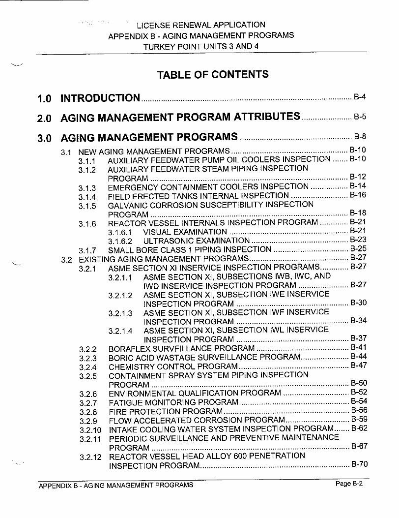
S'' LICENSE RENEWAL APPLICATION
APPENDIX B - AGING MANAGEMENT PROGRAMS
TURKEY POINT UNITS 3 AND 4
TABLE OF CONTENTS
1 .0 IN T R O D U C T IO N ................................................................................................ B-4
2.0 AGING MANAGEMENT PROGRAM ATTRIBUTES ................... B-5
3.0 AGING MANAGEMENT PROGRAMS ................................................... B-8
3.1 NEW AGING MANAGEMENT PROGRAMS ................................................. B-10
3.1.1 AUXILIARY FEEDWATER PUMP OIL COOLERS INSPECTION ....... B-10
3.1.2 AUXILIARY FEEDWATER STEAM PIPING INSPECTION P R O G RA M .......................................................................................... B-12
3.1.3 EMERGENCY CONTAINMENT COOLERS INSPECTION ................. B-14
3.1.4 FIELD ERECTED TANKS INTERNAL INSPECTION .......................... B-16
3.1.5 GALVANIC CORROSION SUSCEPTIBILITY INSPECTION P R O G RA M .......................................................................................... B -18
3.1.6 REACTOR VESSEL INTERNALS INSPECTION PROGRAM ............. B-21 3.1.6.1 VISUAL EXAM INATIO N ...................................................... B-21
3.1.6.2 ULTRASONIC EXAMINATION ............................................ B-23
3.1.7 SMALL BORE CLASS 1 PIPING INSPECTION .................................. B-25
3.2 EXISTING AGING MANAGEMENT PROGRAMS ............................................. B-27
3.2.1 ASME SECTION XI INSERVICE INSPECTION PROGRAMS ............. B-27
3.2.1.1 ASME SECTION XI, SUBSECTIONS IWB, IWC, AND IWD INSERVICE INSPECTION PROGRAM ....................... B-27
3.2.1.2 ASME SECTION XI, SUBSECTION IWE INSERVICE INSPECTION PROGRA M ................................................... B-30
3.2.1.3 ASME SECTION XI, SUBSECTION IWF INSERVICE INSPECTION PROGRAM ................................................... B-34
3.2.1.4 ASME SECTION XI, SUBSECTION IWL INSERVICE INSPECTION PROGRAM ................................................... B-37
3.2.2 BORAFLEX SURVEILLANCE PROGRAM .......................................... B-41
3.2.3 BORIC ACID WASTAGE SURVEILLANCE PROGRAM ...................... B-44
3.2.4 CHEMISTRY CONTROL PROGRAM .................................................. B-47 3.2.5 CONTAINMENT SPRAY SYSTEM PIPING INSPECTION
P R O G RA M .......................................................................................... B -50
3.2.6 ENVIRONMENTAL QUALIFICATION PROGRAM .............................. B-52
3.2.7 FATIGUE MONITORING PROGRAM .................................................. B-54
3.2.8 FIRE PROTECTION PROGRAM ......................................................... B-56 3.2.9 FLOW ACCELERATED CORROSION PROGRAM ............................. B-59
3.2.10 INTAKE COOLING WATER SYSTEM INSPECTION PROGRAM ....... B-62
3.2.11 PERIODIC SURVEILLANCE AND PREVENTIVE MAINTENANCE P R O G R A M .......................................................................................... B -67
3.2.12 REACTOR VESSEL HEAD ALLOY 600 PENETRATION INSPECTIO N PRO G RAM .................................................................... B-70
Page B-2APPENDIX B - AGING MANAGEMENT PROGRAMS

LICENSE RENEWAL APPLICATION
APPENDIX B - AGING MANAGEMENT PROGRAMS TURKEY POINT UNITS 3 AND 4
3.2.13 REACTOR VESSEL INTEGRITY PROGRAM ..................................... B-73 3.2.13.1 REACTOR VESSEL SURVEILLANCE CAPSULE
REMOVAL AND EVALUATION ........................................... B-73 3.2.13.2 FLUENCE AND UNCERTAINTY CALCULATIONS ............. B-75 3.2.13.3 MONITORING EFFECTIVE FULL POWER YEARS ............ B-77 3.2.13.4 PRESSURE-TEMPERATURE LIMIT CURVES ................... B-78
3.2.14 STEAM GENERATOR INTEGRITY PROGRAM ................................. B-80 3.2.15 SYSTEMS AND STRUCTURES MONITORING PROGRAM .............. B-83 3.2.16 THIMBLE TUBE INSPECTION PROGRAM ......................................... B-87
4 .0 R E F E R E N C E S .................................................................................................. B-89
APPENDIX B - AGING MANAGEMENT PROGRAMS Page B-3

LICENSE RENEWAL APPLICATION APPENDIX B - AGING MANAGEMENT PROGRAMS
TURKEY POINT UNITS 3 AND 4
1.0 INTRODUCTION
The Turkey Point Integrated Plant Assessment comprises four major activities,
consistent with the draft NRC, "Standard Review Plan for the Review of License
Renewal Applications for Nuclear Power Plants" [Reference B-i]. The first two
activities, "Identification of Structures and Components that are Subject to Aging
Management Review" and "Identification of Aging Effects Requiring Management,"
have been described in the body of this Application. The remaining major activities,
"Identification of Plant-specific Programs That Will Manage the Identified Aging
Effects Requiring Management" and "Aging Management Demonstration for Existing
Programs," are described herein.
The Turkey Point programs described herein, with the exception of the
Environmental Qualification Program and the Fatigue Monitoring Program, are
credited for managing the effects of aging. The Environmental Qualification
Program is credited for ensuring the qualified life of electrical and I&C components
within the scope of 10 CFR 50.49 is maintained. The Fatigue Monitoring Program is
credited for confirming that Reactor Coolant System design cycle assumptions
remain valid. The programs described include both existing programs and new
programs currently not being conducted. Aging management programs provide reasonable assurance that the effects of aging will be adequately managed so that
the structures and components within the scope of license renewal will continue to
perform their intended functions consistent with the current licensing basis for the period of extended operation. The demonstrations, along with the program and
activity descriptions, meet the requirements of 10 CFR 54.21 (a)(3). Along with the
technical information contained in the body of this Application, this appendix is
intended to allow the NRC to make the finding contained in 10 CFR 54.29(a)(1).
Commitment dates associated with the implementation of new programs and
enhancements to existing programs are contained in Appendix A.
APPENDIX B - AGING MANAGEMENT PROGRAMS Page BAAPPENDIX B - AGING MANAGEMENT PROGRAMS Page B-4
LICENSE RENEWAL APPLICATION
APPENDIX B - AGING MANAGEMENT PROGRAMS
TURKEY POINT UNITS 3 AND 4
2.0 AGING MANAGEMENT PROGRAM ATTRIBUTES
The attributes that are used to describe aging management programs are discussed
in this section. NEI 95-10 [Reference B-2], Sections 4.2 and 4.3, served as the
primary input to the attribute definitions used in this appendix.
Two attributes common to all programs discussed in this appendix are Corrective
Actions and Administrative Controls. They are described as follows:
Corrective Actions
This attribute is a description of the action taken when the established acceptance
criterion or standard is not met. This includes timely root cause determination and
prevention of recurrence, as appropriate.
Administrative Controls
This attribute is an identification of the plant administrative structure under which the
programs are executed.
FPL has established and implemented a Quality Assurance Program to provide
assurance that the design, procurement, modification, and operation of nuclear
power plants conform to applicable regulatory requirements. The FPL Quality
Assurance Program, described in the FPL Topical Quality Assurance Report, is in
compliance with the requirements of 10 CFR 50, Appendix B. The FPL Quality
Assurance Program meets the requirements provided by the NRC Regulatory
Guidance and Industry Standards as listed in Appendix C of the FPL Topical Quality
Assurance Report.
Corrective Actions and Administrative Controls apply to aging management
programs credited for license renewal and performed, or in the case of new
programs to be performed, in accordance with the FPL Quality Assurance Program.
Accordingly, discussion of Corrective Actions and Administrative Controls is not
included in the summary descriptions of the individual programs in this appendix.
APPENDIX B - AGING MANAGEMENT PROGRAMS Page B-5APPENDIX B - AGING MANAGEMENT PROGRAMS Page B-5
LICENSE RENEWAL APPLICATION
APPENDIX B - AGING MANAGEMENT PROGRAMS
TURKEY POINT UNITS 3 AND 4
The remaining attribute definitions used to describe new and existing programs are:
Scope
This attribute is a clear statement of the reason why the program exists for license
renewal.
Preventive Actions
This attribute is a description of preventive actions taken to mitigate the effects of the
susceptible aging mechanisms and basis for the effectiveness of these actions.
Parameters Monitored or Inspected
This attribute is a description of parameters monitored or inspected, and how they
relate to the degradation of the particular component or structure and its intended
function.
Detection of Aging Effects
This attribute is a description of the type of action or technique used to identify or
manage the aging effects or relevant conditions.
Monitoring and Trending
This attribute is a description of the monitoring, inspection, or testing frequency and
sample size (if applicable).
Acceptance Criteria
This attribute is identification of the acceptance criteria or standards for the relevant
conditions to be monitored or the chosen examination methods.
Confirmation Process
This attribute is a description of the process to ensure that adequate corrective
actions have been completed and are effective.
APPENDIX B - AGING MANAGEMENT PROGRAMS Page �-bPage B-6JAPPENDIX B - AGING MANAGEMENT PROGRAMS
"LICENSE RENEWAL APPLICATION
APPENDIX B - AGING MANAGEMENT PROGRAMS
TURKEY POINT UNITS 3 AND 4
Operating Experience and Demonstration
This attribute is a summary of the operating experience of the aging management
program, including past corrective actions resulting in program enhancements or•
additional programs. Program demonstration is also included in this summary.
APPENDIX B - AGING MANAGEMENT PROGRAMS Page B-7APPENDIX B - AGING MANAGEMENT PROGRAMS Page B-7
LICENSE-RENEWAL APPLICATION
APPENDIX B - AGING MANAGEMENT PROGRAMS
TURKEY POINT UNITS 3 AND 4
3.0 AGING MANAGEMENT PROGRAMS
The following programs are credited to manage the aging effects for license renewal.
New Aging Management Programs
"• Auxiliary Feedwater Pump Oil Coolers Inspection
"* Auxiliary Feedwater Steam Piping Inspection Program
"• Emergency Containment Coolers Inspection
"* Field Erected Tanks Internal Inspection
"* Galvanic Corrosion Susceptibility Inspection Program
"* Reactor Vessel Internals Inspection Program
"• Visual Examination
"* Ultrasonic Examination
"* Small Bore Class 1 Piping Inspection
Existing Aging Management Programs
"• ASME Section XI Inservice Inspection Programs
"* ASME Section XI, Subsections IWB, IWC, and IWD Inservice Inspection
Program
"* ASME Section XI, Subsection IWE Inservice Inspection Program
"* ASME Section XI, Subsection IWF Inservice Inspection Program
"* ASME Section XI, Subsection IWL Inservice Inspection Program
"* Boraflex Surveillance Program
"* Boric Acid Wastage Surveillance Program
"* Chemistry Control Program
"* Containment Spray System Piping Inspection Program
"• Environmental Qualification Program
"* Fatigue Monitoring Program
"• Fire Protection Program
APPENDIX B - AGING MANAGEMENT PROGRAMS Page B-8

LICENSE RENEWAL APPLICATION
APPENDIX B - AGING MANAGEMENT PROGRAMS
TURKEY POINT UNITS 3 AND 4
"* Flow Accelerated Corrosion Program
"* Intake Cooling Water System Inspection Program
"* Periodic Surveillance and Preventive Maintenance Program
"* Reactor Vessel Head Alloy 600 Penetration Inspection Program
"• Reactor Vessel Integrity Program
"* Reactor Vessel Surveillance Capsule Removal and Evaluation
"* Fluence and Uncertainty Calculations
"* Monitoring Effective Full Power Years
"* Pressure-Temperature Limit Curves
"* Steam Generator Integrity Program
"* Systems and Structures Monitoring Program
"* Thimble Tube Inspection Program
Demonstration that each of the above programs adequately addresses the identified
aging effect is in the following sections.
APPENDIX B - AGING MANAGEMENT PROGRAMS Page B-9APPENDIX B - AGING MANAGEMENT PROGRAMS Page B-9
LICENSE RENEWAL APPLICATION APPENDIX B - AGING MANAGEMENT PROGRAMS
TURKEY POINT UNITS 3 AND 4
3.1 NEW AGING MANAGEMENT PROGRAMS
3.1.1 AUXILIARY FEEDWATER PUMP OIL COOLERS INSPECTION
As identified in Chapter 3, the Auxiliary Feedwater Pumps Oil Coolers Inspection is credited for aging management of the auxiliary feedwater pumps in Auxiliary Feedwater and Condensate Storage.
Scope
This inspection is intended to be a one-time inspection of an oil cooler of one of the three shared auxiliary feedwater pumps. The Auxiliary Feedwater Pump Oil Coolers Inspection will manage the effects of loss of material due to graphitic corrosion (i.e., selective leaching) and other types of corrosion of the internal surfaces of cast iron parts of the oil coolers wetted internally by treated water - secondary. A visual inspection will be performed to detect loss of material. The inspection will include the cast iron bonnet of one of the auxiliary feedwater pump lube oil coolers and, if necessary, the cast iron parts of an auxiliary feedwater turbine governor controller oil cooler. Commitment dates associated with the implementation of this new program are contained in Appendix A.
Preventive Actions
No preventive actions are applicable to this inspection.
Parameters Monitored or Inspected
The Auxiliary Feedwater Pump Oil Coolers Inspection will identify the presence of graphitic corrosion activity and will quantify the loss of structurally sound wall thickness of cast iron parts. The inspection will consist of two parts, an "as found" inspection of parts and an inspection of parts after light sandblasting to bare metal.
Detection of Aging Effects
Visual inspection will be used to verify whether graphitic corrosion has taken place. The aging effect of concern, loss of material due to graphitic corrosion and other types of corrosion, will be further evident by the reduced wall thickness of structurally sound material in the cast iron parts being examined (following the sandblasting).
APPENDIX B - AGING MANAGEMENT PROGRAMS Page 8-10Page B-10APPENDIX B - AGING MANAGEMENT PROGRAMS
LICENSE RENEWAL APPLICATION
APPENDIX B - AGING MANAGEMENT PROGRAMS
TURKEY POINT UNITS 3 AND 4
Monitoring and Trending
As stated above, this inspection is intended to be a one-time inspection of one
cooler. If significant loss of material due to graphitic corrosion or other corrosion is
detected, Turkey Point will assess the extent of the corrosion, and determine if
inspection of other coolers and additional future monitoring are required.
Acceptance Criteria
If the inspection results in white non-porous metallic surface without major
indications, Turkey Point may declare the part as "not affected by graphitic
corrosion" and not require further evaluation. If there is evidence of significant
effects of graphitic corrosion, an evaluation will be prepared to establish the
minimum required wall thickness including a corrosion allowance adequate for a pre
determined inspection interval. Wall thickness measurements greater than minimum
wall thickness values will be acceptable.
Confirmation Process
Follow-up examination requirements will be established based on the evaluation of
the inspection results and will be entered into the corrective action program.
Operating Experience and Demonstration
Visual inspections and wall thickness measurements of equipment have been
performed at Turkey Point for many years. The techniques have proven successful
in determining actual material condition of components.
This Auxiliary Feedwater Pump Oil Coolers Inspection is a new program that will use
techniques with demonstrated capability and a proven industry record to detect loss
of material due to graphitic corrosion. Visual examination has been used in the past
to identify graphitic corrosion. This inspection will be performed utilizing approved
procedures and qualified personnel.
Based upon the above, the implementation of the Auxiliary Feedwater Pump Oil
Coolers Inspection will provide reasonable assurance that loss of material will be
managed such that components within the scope of license renewal will continue to
perform their intended functions consistent with current licensing basis for the period
of extended operation.
APPENDIX B - AGING MANAGEMENT PROGRAMS Page B-1 1
LICENSE RENEWAL APPLICATION APPENDIX B - AGING MANAGEMENT PROGRAMS
TURKEY POINT UNITS 3 AND 4
3.1.2 AUXILIARY FEEDWATER STEAM PIPING INSPECTION PROGRAM
As identified in Chapter 3, the Auxiliary Feedwater Steam Piping Inspection Program
is credited for aging management of steam piping associated with Auxiliary Feedwater and Condensate Storage.
Scope
The Auxiliary Feedwater Steam Piping Inspection Program will manage the effects
of loss of material due to general and pitting corrosion on the internal and external
surfaces of the auxiliary feedwater steam supply carbon steel piping and fittings.
The program will provide for representative volumetric examinations to detect loss of material in the auxiliary feedwater steam piping between the steam supply check valves and each of the three auxiliary feedwater pump turbines. Commitment dates
associated with the implementation of this new program are contained in
Appendix A.
Preventive Actions
No preventive actions are applicable to this program.
Parameters Monitored or Inspected
The program will monitor the wall thickness of representative piping/fittings in the
auxiliary feedwater steam supply headers and the drain lines upstream of the steam traps. The volumetric examination will identify potential effects of inside diameter corrosion due to accumulation of water at the bottom of horizontal run pipes and
outside diameter corrosion at areas of contact with the lower section of wet
insulation.
Detection of Aging Effects
The aging effect of concern, loss of material due to general and pitting corrosion, will be evident by the reduced wall thickness in the piping/fittings.
Monitoring and Trending
The examination will initially be performed every five years. Piping/fittings thickness measurements will permit calculation of an integrated inside diameter and outside
APPENDIX B - AGING MANAGEMENT PROGRAMS Page B-12

LICENSE-RENEWAL APPLICATION APPENDIX B - AGING MANAGEMENT PROGRAMS
TURKEY POINT UNITS 3 AND 4
diameter corrosion rate. Inspection frequency may be adjusted based on corrosion
rate to insure that the minimum wall thickness requirements will be maintained.
Acceptance Criteria
Wall thickness measurements greater than minimum values for the component design of record will be acceptable. Wall thickness measurements less than required minimum values will be entered into the corrective action program.
Confirmation Process
Follow-up examinations will be based on the evaluation of the examination results and will be documented in accordance with the corrective action program.
Operating Experience and Demonstration
Ultrasonic and computer aided radiography wall thickness measurement techniques have been performed at Turkey Point for years. These techniques have proven successful in determining wall thickness of piping and other components. Computer aided radiography has been used in the auxiliary feedwater steam supply headers and drain lines. The results of these examinations have detected some areas of localized corrosion in the headers.
This new program will use techniques with demonstrated capability and a proven industry record to measure pipe wall thickness. The examinations will be performed utilizing approved plant procedures and qualified personnel.
Based on the above, the implementation of the Auxiliary Feedwater Steam Piping Inspection Program will provide reasonable assurance that loss of material will be managed such that the components within the scope of license renewal will continue to perform their intended functions consistent with the current licensing basis for the period of extended operation.
APPENDIX B - AGING MANAGEMENT PROGRAMS Page B-13Page B-1 3APPENDIX B - AGING MANAGEMENT PROGRAMS

LICENSE RENEWAL APPLICATION APPENDIX B - AGING MANAGEMENT PROGRAMS
TURKEY POINT UNITS 3 AND 4
3.1.3 EMERGENCY CONTAINMENT COOLERS INSPECTION
As identified in Chapter 3, the Emergency Containment Coolers Inspection is
credited for aging management of cooler tubes in Emergency Containment Cooling.
Scope
The Emergency Containment Coolers Inspection is a one-time inspection that will
determine the extent of loss of material due to erosion in the emergency
containment cooler tubes of Units 3 and 4. A sample of tubes for examination will be
selected based on piping geometry and flow conditions that represent those with the
greatest susceptibility to erosion. Commitment dates associated with the
implementation of this new program are contained in Appendix A.
Preventive Actions
No preventive actions are applicable to this inspection.
Parameters Monitored or Inspected
The inspection will document wall thickness of the emergency containment cooler
heat exchanger tubes.
Detection of Aging Effects
The aging effect of concern, loss of material due to erosion, will be detected and
sized in accordance with the volumetric technique chosen.
Monitoring and Trending
As stated above, this is a one-time inspection and as such no monitoring and
trending is anticipated. The evaluation of the inspection results may result in
additional testing, monitoring, and trending.
Acceptance Criteria
The results of the inspection will be evaluated by Turkey Point to verify that the
minimum required wall thickness for the emergency containment cooler heat
exchanger tubes will be maintained during the period of extended operation.
APPENDIX B - AGING MANAGEMENT PROGRAMS Page B-14APPENDIX B - AGING MANAGEMENT PROGRAMS Page B-14

LICENSE RENEWAL APPLICATION
APPENDIX B - AGING MANAGEMENT PROGRAMS
TURKEY POINT UNITS 3 AND 4
Confirmation Process
Any follow-up inspection required will be based on the evaluation of the inspection
results and will be documented in accordance with the corrective action program.
Operating Experience and Demonstration
This one-time inspection is a new activity that will use techniques with demonstrated
capability and a proven industry record to detect wall thickness (loss of material due
to erosion). Effective and proven volumetric examination techniques will be selected
for use in performing this inspection. This inspection will be performed utilizing
approved procedures and qualified personnel.
Based upon the above, the implementation of the Emergency Containment Coolers
Inspection will provide reasonable assurance that loss of material due to erosion will
be managed such that the components within the scope of license renewal will
continue to perform their intended functions consistent with the current licensing
basis for the period of extended operation.
APPENDIX B - AGING MANAGEMENT PROGRAMS Page B-15APPENDIX B - AGING MANAGEMENT PROGRAMS Page B-1 5
LICENSE RENEWAL APPLICATION
APPENDIX B - AGING MANAGEMENT PROGRAMS
TURKEY POINT UNITS 3 AND 4
3.1.4 FIELD ERECTED TANKS INTERNAL INSPECTION
As discussed in Chapter 3, the Field Erected Tanks Internal Inspection is credited for
aging management of field erected tanks in the following systems:
"* Auxiliary Feedwater and Condensate Storage
"* Feedwater and Blowdown
"* Safety Injection
Scope
This is a one-time inspection of the two condensate storage tanks, two refueling
water storage tanks, and the shared demineralized water storage tank. The Field
Erected Tanks Internal Inspection is credited with managing the aging effect of loss
of material due to corrosion of the tanks within the scope. The one-time inspection
of selected internal areas, including surface welds, will determine the extent of
internal corrosion in the listed tanks. The visual inspection will consist of direct (e.g.,
divers) or remote (e.g., television cameras, fiber optic scopes, periscopes) means.
Commitment dates associated with the implementation of this new program are
contained in Appendix A.
Preventive Actions
Internal tank surfaces are coated to reduce corrosion. Coatings minimize corrosion
by limiting exposure to the environment. However, coatings are not credited in the determination of the aging effects requiring management.
Parameters Monitored or Inspected
The material condition of the internal surfaces of accessible areas of the tanks will
be visually inspected.
Detection of Aging Effects
The presence of corrosion that could lead to loss of material will be determined by
visual inspection of the accessible areas of the field erected tanks. Internal surfaces
will be examined for evidence of flaking, blistering, peeling, discoloration, pitting, or
excessive corrosion.
APPENDIX B - AGING MANAGEMENT PROGRAMS Page B-1 6
.. LICENSE RENEWAL APPLICATION
APPENDIX B - AGING MANAGEMENT PROGRAMS
TURKEY POINT UNITS 3 AND 4
Monitoring and Trending
As noted above, this is a one-time inspection, therefore, monitoring or trending is not
anticipated. Results of the inspection will be evaluated to determine if additional
actions are required.
Acceptance Criteria
The results of the one-time inspection will be evaluated. Specific acceptance criteria
will be provided in the implementing procedure.
Confirmation Process
Any follow-up inspection required will be based on the evaluation of the inspection results and will be documented in accordance with the corrective action program.
Operating Experience and Demonstration
Visual inspections have been performed at Turkey Point for several years. This technique has proven successful for identifying material defects on the surface of
field erected tanks.
This inspection is a new activity that will use techniques with demonstrated capability
and a proven industry record to detect corrosion. This inspection will be performed
utilizing approved procedures and qualified personnel.
Based upon the above, the implementation of the Field Erected Tanks Internal
Inspection will provide reasonable assurance that loss of material due to corrosion will be managed such that the structures and components within the scope of license renewal will continue to perform their intended functions consistent with the
current licensing basis for the period of extended operation.
APPENDIX B - AGING MANAGEMENT PROGRAMS Page 8-17APPENDIX B - AGING MANAGEMENT PROGRAMS Page B-1 7
LICENSE RENEWAL APPLICATION
APPENDIX B - AGING MANAGEMENT PROGRAMS
TURKEY POINT UNITS 3 AND 4
3.1.5 GALVANIC CORROSION SUSCEPTIBILITY INSPECTION PROGRAM
As identified in Chapter 3, the Galvanic Corrosion Susceptibility Inspection Program
is credited for aging management of specific component/commodity groups in the
following systems:
Auxiliary Feedwater and Fire Protection Condensate Storage
Instrument Air Chemical and Volume Control
Normal Containment and Control Component Cooling Water Rod Drive Mechanism Cooling
Containment Spray Reactor Coolant
Control Building Ventilation Residual Heat Removal
Emergency Containment Cooling Safety Injection
Emergency Diesel Ger~erators Spent Fuel Pool Cooling and Support Systems Turbine Building Ventilation
Feedwater and Blowdown Waste Disposal
Scope
The Galvanic Corrosion Susceptibility Inspection Program will manage the potential
effects of loss of material due to galvanic corrosion on the internal surfaces of
susceptible piping and components. Carbon steel components directly coupled to
stainless steel components in raw water systems at Turkey Point are the most
susceptible to galvanic corrosion. However, baseline examinations will be
performed and evaluated to establish if the corrosion mechanism is active in other
systems. The program will involve selected one-time inspections (see Monitoring
and Trending below) whose results will be utilized to determine the need for
additional actions. Commitment dates associated with the implementation of this
new program are contained in Appendix A.
Preventive Actions
Components and systems utilize insulating flanges or cathodic protection to
minimize galvanic corrosion. The use of insulated flanges and cathodic protection is
not credited with the elimination of galvanic corrosion.
APPENDIX B - AGING MANAGEMENT PROGRAMS Page B-1 8

LICENSE RENEWAL APPLICATION
APPENDIX B - AGING MANAGEMENT PROGRAMS
TURKEY POINT UNITS 3 AND 4
Parameters Monitored or Inspected
The program will assess the loss of material due to galvanic corrosion between
dissimilar metals in locations determined to represent the most limiting conditions.
Selection of the most limiting conditions will be based on high galvanic potential,
high cathode/anode area ratio, and high conductivity of the fluid in contact with the
materials.
Detection of Aging Effects
Loss of material due to galvanic corrosion will be evident by material loss at the
location of the junction between the dissimilar metals. Volumetric examinations or
visual inspections will be utilized to address the extent of material loss.
Monitoring and Trending
Inspections will be conducted on a sampling basis. Locations selected for inspection
will represent those with the greatest susceptibility for galvanic corrosion (i.e.,
greatest galvanic potential, high cathode/anode area ratio, and high fluid
conductivity). Initial inspection results will be utilized to assess the need for
expanded sample locations. Inspection frequency will be determined based on the
corrosion rate identified during the initial inspections.
Acceptance Criteria
Wall thickness measurements greater than required minimum wall thickness values
for the components will be acceptable. Wall thickness measurements less than
required minimum values will be entered into the corrective action program.
Confirmation Process
Any follow-up examination required will be based on the evaluation of the
examination results and will be documented in accordance with the corrective action
program.
Operating Experience and Demonstration
Visual and volumetric inspection techniques have been used at Turkey Point for
years. These techniques have proven successful in determining material condition
of components.
Page B-1 9APPENDIX B - AGING MANAGEMENT PROGRAMS
LICENSE RENEWAL APPLICATION
APPENDIX B - AGING MANAGEMENT PROGRAMS
TURKEY POINT UNITS 3 AND 4
This is a new program that will use techniques with demonstrated capability and a
proven industry record to monitor material loss due to galvanic corrosion. This
examination will be performed utilizing approved procedures and qualified
personnel. The inspection techniques used in this program have been previously
used to monitor material condition for plant systems.
Based upon the above, the implementation of the Galvanic Corrosion Susceptibility
Inspection Program will provide reasonable assurance that loss of material due to
galvanic corrosion will be managed such that the systems and components within
the scope of license renewal will continue to perform their intended functions
consistent with the current licensing basis for the period of extended operation.
APPENDIX B - AGING MANAGEMENT PROGRAMS Page B-20APPENDIX B - AGING MANAGEMENT PROGRAMS Page B-20
LICENSE RENEWAL APPLICATION APPENDIX B - AGING MANAGEMENT PROGRAMS
TURKEY POINT UNITS 3 AND 4
3.1.6 REACTOR VESSEL INTERNALS INSPECTION PROGRAM
As identified in Chapter 3, the Reactor Vessel Internals Inspection Program is
credited for aging management of the reactor vessel internals in the Reactor Coolant
Systems.
The Reactor Vessel Internals Inspection Program will involve the combination of
several activities culminating in the inspection of the Turkey Point Units 3 and 4
reactor vessel internals once for each unit during the 20-year period of extended
operation, as described below. This program is intended to supplement the reactor
vessel internals inspections required by the ASME Section XI, Subsections IWB,
IWC, and IWD Inservice Inspection Program. Ongoing industry efforts are aimed at
characterizing the aging effects associated with the reactor vessel internals. Further
understanding of these aging effects will be developed by the industry over time and
will provide additional bases for the inspections under this program. Pending results
of industry progress with regard to validation of the significance of dimensional
changes due to void swelling, the visual examinations described below may be
supplemented to incorporate requirements for measurement of critical parts to
evaluate potential dimensional changes. Accordingly, an evaluation will be performed to establish the requirements for dimensional verification of critical reactor vessel internals parts as part of the visual examination scope.
The Reactor Vessel Internals Inspection Program consists of two types of
examinations, visual and ultrasonic testing. These examinations will manage the aging effects of cracking, reduction in fracture toughness, and loss of mechanical
closure integrity. Commitment dates associated with the implementation of this new
program are contained in Appendix A.
3.1.6.1 VISUAL EXAMINATION
Scope
This activity will manage the aging effects of cracking due to irradiation assisted stress corrosion (IASCC) and reduction in fracture toughness due to irradiation and
thermal embrittlement on accessible parts of the Turkey Point Units 3 and 4 reactor
vessel internals. The reactor vessel internals parts susceptible to these aging
effects and included in the visual examination scope are accessible areas of the
lower core plates and fuel pins, lower support columns, core barrels, baffle/former
assemblies, thermal shields, and lower support castings. The program will consist of
APPENDIX B - AGING MANAGEMENT PROGRAMS Page B-21

" '. LICENSE RENEWAL APPLICATION APPENDIX B - AGING MANAGEMENT PROGRAMS
TURKEY POINT UNITS 3 AND 4
VT-1 examinations utilizing remote equipment such as television cameras, fiberoptic
scopes, periscopes, etc.
Preventive Actions
There are no practical preventive actions available that will prevent IASCC and
reduction in fracture toughness. However, to minimize the potential for IASCC, the
concentrations of chlorides, fluorides, and sulfates in the reactor coolant are
controlled by implementation of the Chemistry Control Program.
Parameters Monitored or Inspected
This examination monitors the effects of cracking and reduction in fracture
toughness on the reactor vessel internals selected parts by the detection and sizing
of cracks.
Detection of Aging Effects
IASCC and reduction in fracture toughness of reactor vessel internals selected parts will be detected by performance of VT-i examinations for the detection of cracks.
Cracking is expected to initiate at the surface and, therefore, will be detectable by
visual examination.
Monitoring and Trending
The VT-1 examination of selected parts of the reactor vessel internals will be performed one time for each unit during the period of extended operation. Based on
the results of each examination, additional examinations and/or repairs will be
scheduled.
Acceptance Criteria
Acceptance criteria will be developed prior to the visual examination. Cracks will be
evaluated for determination of the need and method of repair.
Confirmation Process
Any follow-up examination will be based on the evaluation of the initial examination
results and will be documented in accordance with the corrective action program.
APPENDIX B - AGING MANAGEMENT PROGRAMS Page B-22APPENDIX B - AGING MANAGEMENT PROGRAMS Page B-22
LICENSE'RENEWAL APPLICATION
APPENDIX B - AGING MANAGEMENT PROGRAMS
TURKEY POINT UNITS 3 AND 4
Operating Experience and Demonstration
The remote visual examination proposed by this program utilizing equipment such
as television cameras, fiberoptic scopes, periscopes, etc., has been demonstrated
previously as an effective method to detect cracking of reactor vessel internals.
Similar visual examinations were successfully performed at St. Lucie Unit 1 during
the core barrel repair/modification.
3.1.6.2 ULTRASONIC EXAMINATION
Scope
This activity manages the aging effect of loss of mechanical closure integrity on
reactor vessel internals baffle/former bolts, barrel/former bolts, and lower support
column bolts. The volumetric examination will involve ultrasonic testing on the
baffle/former bolts in each unit to supplement the current examination techniques.
The results of this examination will be utilized to determine the need for similar
examinations of the barrel/former bolts, lower support column bolts, and other
reactor vessel internals bolting.
Preventive Actions
There are no practical preventive actions available that will prevent loss of
mechanical closure integrity of reactor vessel internals bolting. However, to
minimize the potential for loss of mechanical closure integrity due to IASCC, the
concentrations of chlorides, fluorides, and sulfates in the reactor coolant are
controlled by implementation of the Chemistry Control Program.
Parameters Monitored or Inspected
This examination monitors loss of mechanical closure integrity of the reactor vessel
internals bolts by the detection and sizing of cracks.
Detection of Aging Effects
The aging effect of loss of mechanical closure integrity of reactor vessel internals
bolting will be detected by performance of ultrasonic examinations.
APPENDIX B - AGING MANAGEMENT PROGRAMS Page B-23Page B-23APPENDIX B - AGING MANAGEMENT PROGRAMS
LICENSE RENEWAL APPLICATION
APPENDIX B - AGING MANAGEMENT PROGRAMS
TURKEY POINT UNITS 3 AND 4
Monitoring and Trending
The ultrasonic examination of the reactor vessel internals baffle/former bolts will be
performed one time during the period of extended operation. Based on the results of
the examination, additional examinations and/or repairs will be scheduled.
Acceptance Criteria
The quantity of cracked baffle/former bolts shall be less than the number of bolts that
can be damaged without affecting the intended function of the reactor vessel
internals. This quantity will be established by evaluation.
Confirmation Process
Any follow-up examination will be based on the evaluation of the initial examination
results and will be documented in accordance with the corrective action program.
Operating Experience and Demonstration
The ultrasonic examination methods are proven techniques that have been used in
other programs to successfully detect cracking. Ultrasonic examinations have been
demonstrated as an effective method of detecting cracking in baffle/former bolting at
other Westinghouse plants.
The ultrasonic examinations utilize techniques with a demonstrated capability and a
proven industry record to detect cracking. These examinations are performed
utilizing approved procedures and qualified personnel.
Based upon the above, the implementation of the Reactor Vessel Internals Inspection Program will provide reasonable assurance that cracking, reduction in
fracture toughness, and loss of mechanical closure integrity will be managed such
that reactor vessel internals components within the scope of license renewal will
continue to perform their intended functions consistent with the current licensing
basis for the period of extended operation.
APPENDIX B - AGING MANAGEMENT PROGRAMS Page B-24Page B-24APPENDIX B - AGING MANAGEMENT PROGRAMS

LICENSE RENEWAL APPLICATION
APPENDIX B - AGING MANAGEMENT PROGRAMS
TURKEY POINT UNITS 3 AND 4
3.1.7 SMALL BORE CLASS 1 PIPING INSPECTION As identified in Chapter 3, the Small Bore Class 1 Piping Inspection is credited for
aging management of small bore Class 1 piping in the Reactor Coolant Systems.
Scope
The Small Bore Class 1 Piping Inspection will be a one-time inspection of a sample
of Class 1 piping less than 4 inches in diameter. Commitment dates associated with
the implementation of this new program are contained in Appendix A.
Preventive Actions
No preventive actions are applicable to this inspection.
Parameters Monitored or Inspected
The volumetric technique chosen will permit detection and sizing of significant
cracking of small bore Class 1 piping.
Detection of Aging Effects
The aging effect requiring management, cracking, will be detected and sized in
accordance with the volumetric technique chosen.
Monitoring and Trending
As noted above, this is a one-time inspection and as such, no monitoring and
trending is anticipated. The evaluation of the inspection results may result in
additional examinations consistent with ASME Section XI, Subsection IWB. A small
sample of the affected welds will be selected for examination based on piping
geometry, piping size, and flow conditions.
Acceptance Criteria
Any cracks identified will be evaluated and, if appropriate, entered into the corrective
action program.
Confirmation Process
Any follow-up inspection required will be based on the evaluation of the inspection
results and will be documented in accordance with the corrective action program.
APPENDIX B - AGING MANAGEMENT PROGRAMS Page B-25

LICENSE RENEWAL APPLICATION
APPENDIX B - AGING MANAGEMENT PROGRAMS
TURKEY POINT UNITS 3 AND 4
Operating Experience and Demonstration
This one-time inspection is a new activity, which will use techniques with
demonstrated capability and a proven industry record to detect piping weld and base
material flaws. Effective and proven volumetric examination techniques will be
selected for use in performing this inspection. This inspection will be performed
utilizing approved procedures and qualified personnel. Results and
recommendations from industry initiatives will be incorporated into the inspection.
Based upon the above, the Small Bore Class 1 Piping Inspection will provide
reasonable assurance that cracking in small bore Class 1 piping welds will be
managed such that components within the scope of license renewal will continue to
perform their intended functions consistent with the current licensing basis for the
period of extended operation.
APPENDIX B - AGING MANAGEMENT PROGRAMS Page B-26Page B-26APPENDIX B - AGING MANAGEMENT PROGRAMS
LICENSE RENEWAL APPLICATION
APPENDIX B - AGING MANAGEMENT PROGRAMS
TURKEY POINT UNITS 3 AND 4
3.2 EXISTING AGING MANAGEMENT PROGRAMS
3.2.1 ASME SECTION XI INSERVICE INSPECTION PROGRAMS
The ASME Section XI Inservice Inspection Programs within the scope of license
renewal include the following:
"• ASME Section XI, Subsections IWB, IWC, and IWD Inservice Inspection
Program
"• ASME Section XI, Subsection IWE Inservice Inspection Program
"* ASME Section XI, Subsection IWF Inservice Inspection Program
"* ASME Section XI, Subsection IWL Inservice Inspection Program
3.2.1.1 ASME SECTION XI, SUBSECTIONS IWB, IWC, AND IWD INSERVICE
INSPECTION PROGRAM
As identified in Chapter 3, the ASME Section XI, Subsections IWB, IWC, and IWD
Inservice Inspection Program is credited for aging management of specific
component/commodity groups in the Reactor Coolant Systems.
A request to revise the Turkey Point Unit 3 inservice inspection scope for Class 1
piping to risk informed inservice inspection (RI-ISI) has been submitted to the NRC
[Reference B-3]. The revision affects the nondestructive examination (NDE) scope
of Class 1 piping currently required by ASME Section XI. Examinations performed
are based upon the postulated failure mechanism associated with the piping being
inspected. A similar revision request will be submitted for Turkey Point Unit 4 at a
later date.
Scope
This program, as defined by the Third Interval Inservice Inspection Program for
Turkey Point Nuclear Units 3 and 4 [Reference B-4], is credited with managing the
aging effects of cracking, loss of mechanical closure integrity, and loss of material
for piping and components. This program provides inspection and examination of
accessible components, including welds, pump casings, valve bodies, steam
generator tubing, and pressure-retaining bolting.
Inservice inspection requirements may be modified by applicable relief requests and
code cases that are approved specifically for each unit. A particular code edition is
APPENDIX B - AGING MANAGEMENT PROGRAMS Page B-27

LICENSE'RENEWAL APPLICATION
APPENDIX B - AGING MANAGEMENT PROGRAMS TURKEY POINT UNITS 3 AND 4
applicable for a 120-month interval. Prior to the end of each interval, the program is
revised to reflect the update requirements of 10 CFR 50.55a.
Although ASME Section XI, Subsection IWD is included in the scope of this
program, this Application does not credit Subsection IWD for managing the effects of
aging.
Preventive Actions
There are no specific preventive actions under this program to prevent the effects of
aging. Specific actions that serve to limit the effects of aging for Class 1, 2, and 3
piping and components are conservative design, fabrication, construction, inservice
inspections, and strict control of chemistry.
Parameters Monitored or Inspected
Inservice examinations include visual inspections, surface examinations, and
volumetric examinations in accordance with the requirements of ASME Section XI.
Detection of Aging Effects
The degradation of piping and components is determined by visual, surface, or
volumetric examination in accordance with the requirements of ASME Section X1 as
modified by the Third Interval Inservice Inspection Program for Turkey Point Nuclear
Units 3 and 4 [Reference B-4]. Piping and components are examined for evidence
of operation-induced flaws using volumetric and surface techniques. The VT-1
visual examination is used to detect cracks, symptoms of wear, corrosion, erosion,
or physical damage. VT-2 examinations are conducted to detect evidence of
leakage from pressure-retaining components. VT-3 examinations are conducted to
determine the general mechanical and structural condition of components and to
detect discontinuities and imperfections such as loss of integrity at bolted or welded
connections, loose or missing parts, debris, corrosion, wear, or erosion. The extent
and frequency of inspections is specified in ASME Section XI as modified in
accordance with the Third Interval Inservice Inspection Program for Turkey Point
Nuclear Units 3 and 4 [Reference B-4]. The frequency and scope of examinations
are sufficient to ensure that the aging effects are detected prior to impacting the
component intended functions. The inspection intervals are not restricted by the
Code to the current term of operation and are valid for the period of extended
operation.
APPENDIX B - AGING MANAGEMENT PROGRAMS Page B-28

LICENSE RENEWAL APPLICATION
APPENDIX B - AGING MANAGEMENT PROGRAMS
TURKEY POINT UNITS 3 AND 4
Monitoring and Trending
The frequency and scope of examinations are sufficient to ensure that the aging
effects are detected before impacting the component intended functions.
Inspections are performed in accordance with the inspection intervals specified by
ASME Section XI as modified by the Third Interval Inservice Inspection Program for
Turkey Point Nuclear Units 3 and 4 [Reference B-4].
Examinations performed during any inspection interval that reveal flaws or areas of
degradation exceeding the acceptance criteria are to be extended to include
additional examinations within the same category. When examination results
require evaluation of flaws or areas of degradation, the areas are reexamined during
subsequent inspection intervals in accordance with the requirements of ASME
Section XI.
Records of the inspection program, examination and test procedures, results of
activities, examination/test data, and corrective actions taken or recommended are
maintained in accordance with the requirements of ASME Section XI, Subsection IWA.
Acceptance Criteria
Acceptance standards for the inservice inspections are identified in ASME Section
XI. Relevant indications that are revealed by the inservice inspections may require
additional inspections of similar components in accordance with ASME Section XI.
Examinations that reveal indications exceeding the acceptance standards are made
acceptable by repair, replacement, or evaluation.
Confirmation Process
When areas of degradation are identified, an evaluation is performed to determine if
repair or replacement is required. The results are documented in accordance with
the corrective action program. Reexaminations are conducted for repaired flaws or
areas of degradation to demonstrate that the repairs meet the acceptance
standards.
Operating Experience and Demonstration
ASME Section XI provides the rules and requirements for inservice inspection,
testing, repair, and replacement of Class 1, 2, and 3 components. Components are
APPENDIX B - AGING MANAGEMENT PROGRAMS Page B-29
LICENSE RENEWAL APPLICATION
APPENDIX B - AGING MANAGEMENT PROGRAMS
TURKEY POINT UNITS 3 AND 4
chosen for inspection in accordance with the requirements of Subsections IWB,
IWC, and IWD and are inspected using the volumetric, surface, or visual
examination methods.
The ASME Section XI inspections are conducted as part of the inservice inspections
typically performed during plant refueling outages. The inservice inspection of Class
1, 2, and 3 components and piping has been conducted since initial plant start-up as
required by the plant Technical Specifications and 10 CFR 50.55a. These
inspections have documented, evaluated, and corrected degraded conditions
associated with piping and components inspected under the program.
Implementation of the ASME Section XI program at Turkey Point currently includes
over 480 Class 1, Class 2, and Class 3 examinations per unit per ten-year interval.
For Class 1 piping, the examinations have yielded only indications of surface
anomalies and surface geometry with no indication of fatigue cracking. For Class 2
piping, the only indications have been surface anomalies, acceptable slag
inclusions, surface geometry, and fatigue cracking of steam generator feedwater
nozzle reducers. The feedwater reducers were replaced and subsequent
inspections are being performed in accordance with the requirements of ASME
Section XI (see Section 3.2).
Based on the above, the ASME Section XI, Subsections IWB, IWC, and IWD
Inservice Inspection Program provides reasonable assurance that the aging effects
of cracking, loss of mechanical closure integrity, and loss of material will be
managed such that components within the scope of license renewal will continue to
perform their intended functions consistent with the current licensing basis for the
extended period of operation.
3.2.1.2 ASME SECTION Xl, SUBSECTION IWE INSERVICE INSPECTION PROGRAM
As identified in Chapter 3, the ASME Section XI, Subsection IWE Inservice
Inspection Program is credited for aging management of specific structural
component/commodity groups in the Containments.
Scope
The ASME Section XI, Subsection IWE Inservice Inspection Program is credited with
managing the effects of loss of material for containment steel components and
change in material properties for elastomers (seals, gaskets, and moisture barriers)
associated with containment steel components. The program provides inspection
Page B-30APPENDIX B - AGING MANAGEMENT PROGRAMS

LICENSE RENEWAL APPLICATION
APPENDIX B - AGING MANAGEMENT PROGRAMS
TURKEY POINT UNITS 3 AND 4
and examination of accessible surface areas, including surfaces of welds, pressure
retaining bolting, and moisture barriers intended to prevent intrusion of moisture
against inaccessible Containment metallic surfaces.
Preventive Actions
Visual inspections are performed to detect loss of material due to general corrosion
and change in material properties of elastomers due to embrittlement and
permanent set. Carbon steel surfaces are typically coated, in accordance with plant
procedures, to reduce the effects of loss of material due to corrosion. In addition,
cathodic protection and moisture barriers are used where appropriate to minimize
corrosion. However, coatings, cathodic protection, and moisture barriers are not
credited in the determination of the aging effects requiring management.
Parameters Monitored or Inspected
The ASME Section Xl, Subsection IWE Inservice Inspection Program provides for
examination of the following categories as defined by ASME Section XI, Subsection IWE and the Turkey Point Inservice Inspection Program:
"* Examination Category E-A, Containment Surfaces
"* Examination Category E-C, Containment Surfaces Requiring Augmented
Examination
"* Examination Category E-D, Seals, Gaskets, and Moisture Barriers
"* Examination Category E-G, Pressure-retaining Bolting
"• Examination Category E-P, All Pressure-retaining Components
Surface conditions are monitored through visual examinations to determine the
existence of corrosion. Surfaces that are inaccessible require an evaluation of the
acceptability when conditions in accessible areas exist that could indicate the presence of or result in degradation to such inaccessible areas. Moisture barriers
are visually inspected for degradation per Category E-D. Seals and gaskets are
pressure tested in accordance with 10 CFR 50, Appendix J, per Category E-P.
Detection of Aging Effects
The presence of corrosion that could lead to loss of material is determined by visual
inspection of the steel components. Surfaces are examined for evidence of flaking,
APPENDIX B - AGING MANAGEMENT PROGRAMS Page B-31

LICENSE RENEWAL APPLICATION
APPENDIX B - AGING MANAGEMENT PROGRAMS
TURKEY POINT UNITS 3 AND 4
blistering, peeling, discoloration, wear, pitting, excessive corrosion, arc strikes,
gouges, surface discontinuities, dents, or other signs of surface irregularities.
All pressure-retaining components, per Category E-P, require leakage testing in
accordance with 10 CFR 50, Appendix J, to evaluate the change in material
properties for airlocks, seals, and gaskets. Under the inspection plan, 100% of the
accessible surfaces are inspected during the inspection intervals as established by
the ASME Section XI, Subsection IWE, Inservice Inspection Program.
Monitoring and Trending
In accordance with the requirements of 10 CFR 50.55a, the first-period inspections
for Turkey Point are scheduled for completion prior to September 9, 2001.
Subsequent inspections are performed in accordance with the inspection intervals
specified by ASME Section Xl, Subsection IWE, and the ASME Section XI,
Subsection IWE Inservice Inspection Program.
Surface areas likely to experience accelerated degradation and aging require
augmented examinations and include areas as determined by the ASME Section XI,
Subsection IWE Inservice Inspection Program. Identification of the areas subject to
augmented examinations will be accomplished in accordance with the corrective
action program and monitoring of industry events.
Examinations performed during any inspection interval that reveal flaws or areas of
degradation exceeding the acceptance criteria are expanded to include additional
examinations within the same category. When examination results require
evaluation of flaws or areas of degradation, the area(s) are reexamined during the
next inspection interval. Flaws or areas of degradation are documented and
evaluated in accordance with the corrective action program and the requirements of
the ASME Section XI, Subsection IWE Inservice Inspection Program.
Acceptance Criteria
Examinations and evaluations are performed under the direction of the Responsible
Engineer in accordance with the requirements of ASME Section XI, Subsection IWE,
and the ASME Section XI, Subsection IWE Inservice Inspection Program.
Inspection results are evaluated against the acceptance standards of the program.
Inspections that reveal evidence of degradation exceeding the acceptance
standards may be subject to additional inspections to determine the nature and
extent of the condition.
APPENDIX B - AGING MANAGEMENT PROGRAMS Page B-32

LICENSE RENEWAL APPLICATION
APPENDIX B - AGING MANAGEMENT PROGRAMS
TURKEY POINT UNITS 3 AND 4
Confirmation Process
When areas of degradation are identified, an evaluation is performed to determine if
repair or replacement is required. The results are documented in accordance with
the corrective action program. Reexaminations are conducted for repaired flaws or
areas of degradation to demonstrate that the repairs meet the acceptance
standards.
Operating Experience and Demonstration
ASME Section XI, Subsection IWE was recently incorporated by reference in
10 CFR 50.55a and, accordingly, the Turkey Point program was developed. Full
implementation is scheduled for September 2001. The current inspections of the
containment liner are conducted in accordance with the Containment Leak Rate
Testing Program and the Maintenance Rule Implementation Program. The
inspections performed under these programs were previously documented and
evaluated for any degraded conditions associated with the containment liner.
Containment leak-tight verification and visual examination of the steel components
that are part of the leak-tight barrier have been conducted at Turkey Point since
initial unit startup. Prior to the development of the ASME Section XI, Subsection
IWE Inservice Inspection Program, examinations were performed in accordance with
10 CFR 50, Appendix J. Appendix J requires that licensees provide for
preoperational and periodic verification, by performing tests of the leak-tight integrity
of the Containment, and systems and components that penetrate the Containment.
Approved plant procedures provide the requirements, precautions/limitations, and
acceptance criteria for the visual inspection of Unit 3 and Unit 4 accessible interior
and exterior Containment surfaces, including the liner plate. Detailed inspections
and evaluations are performed as warranted if gross discrepancies are detected. All
conditions noted during the inspection of the Containment are documented on
inspection reports. The inspection procedures provide general guidelines for
inspection in accordance with NEI 94-01, "Industry Guidelines for Implementing
Performance-Based Options of 10 CFR Part 50, Appendix J" [Reference B-6].
Material properties for non-metallic components, such as gaskets and seals, change
over time and are replaced in accordance with approved plant procedures. The
Appendix J tests performed at the Turkey Point units during the years of operation
have not shown any loss of intended function of the containment steel components
that were attributed to loss of material or other aging effects.
APPENDIX B - AGING MANAGEMENT PROGRAMS Page B-33
LICENSE RENEWAL APPLICATION
APPENDIX B - AGING MANAGEMENT PROGRAMS TURKEY POINT UNITS 3 AND 4
The ASME Section XI, Subsection IWE Inservice Inspection Program incorporates
the inspection criteria from the current inspection programs, which are similar to the
Subsection IWE requirements.
FPL's Nuclear Quality Assurance Department performed an audit on the program
and concluded that the Turkey Point ASME Section XI, Subsection IWE Inservice
Inspection Program met the requirements of 10 CFR 50.55a and ASME Section XI, Subsection IWE, for inspection of Class CC metallic liners and pressure retention
components.
The NRC Safety Evaluation Report for the Turkey Point Inservice Inspection
Program [Reference B- 5] concluded there were no deviations from the regulatory
requirements or commitments.
Based on the above, the continued examinations performed under the guidance of
the ASME Section XI, Subsection IWE Inservice Inspection Program provide
reasonable assurance that the aging effects loss of material and change of material
properties for the containment steel components within the scope of license renewal
will be managed for the period of extended operation.
3.2.1.3 ASME SECTION Xl, SUBSECTION IWF INSERVICE INSPECTION PROGRAM
As identified in Chapter 3, the ASME Section XI, Subsection IWF Inservice
Inspection Program is credited for aging management of Class 1, 2, and 3 component supports in the following structures:
"* Auxiliary Building
"* Containments
"* Emergency Diesel Generator Buildings
"* Yard Structures
Scope
The ASME Section XI, Subsection IWF Inservice Inspection Program is credited with
managing the aging effect of loss of material for Class 1, 2, and 3 component
supports. The scope of the Turkey Point program provides inspection and
examination of accessible surface areas of these component supports.
APPENDIX B - AGING MANAGEMENT PROGRAMS Page B-34APPENDIX B - AGING MANAGEMENT PROGRAMS Page B-34

LICENSE RENEWAL APPLICATION
APPENDIX B - AGING MANAGEMENT PROGRAMS
TURKEY POINT UNITS 3 AND 4
Preventive Actions
Carbon steel surfaces are typically coated, in accordance with plant procedures, to
reduce the effects of loss of material due to corrosion. Coatings minimize corrosion
by limiting exposure to the environment. However, coatings are not credited in the
determination of the aging effects requiring management.
Parameters Monitored or Inspected
Class 1, 2, and 3 component supports are examined in accordance with ASME
Section X1, Subsection IWF. The ASME Section XI, Subsection IWF Inservice
Inspection Program provides for visual examination for general corrosion that could
reduce the structural capacity of the component supports.
Detection of Aging Effects
The presence of corrosion that could lead to loss of material is determined by visual
inspection of component supports. Surfaces are examined for evidence of flaking,
blistering, peeling, discoloration, wear, pitting, corrosion, arc strikes, gouges, surface
discontinuities, dents, or other signs of surface irregularities. The extent and
frequency of the inspections is in accordance with ASME Section XI, Subsection IWF.
Monitoring and Trending
The selected supports are monitored each inspection period. The program inspects
25% of non-exempt Class 1 piping supports, 15% of Class 2 piping supports, and
10% of Class 3 piping supports, including exposed surfaces of structural bolting. For
those component supports within a system that have similar design, function, and
service, only one support is examined. Unacceptable supports are subject to
corrective measures or evaluation, and are re-examined during the next inspection
period.
Acceptance Criteria
Acceptance standards for the examination and evaluation of supports are provided
in ASME Section XI, Subsection IWF. A condition observed during a visual
examination that requires supplemental examination, corrective measures, repair,
replacement, or analytical evaluation is categorized as a relevant condition and is
not considered acceptable.
Page B-35APPENDIX B - AGING MANAGEMENT PROGRAMS
LICENSE RENEWAL APPLICATION
APPENDIX B - AGING MANAGEMENT PROGRAMS TURKEY POINT UNITS 3 AND 4
Confirmation Process
Component supports subject to corrective measures in accordance with ASME
Section XI, Subsection IWF, are re-examined during the next inspection period and
documented in accordance with the corrective action program. If additional
corrective measures are not required, the examinations revert back to the original
schedule of successive inspection intervals.
Operating Experience and Demonstration
The ASME Section XI, Subsection IWF, inspections are conducted as part of the
inservice inspections typically during plant refueling outages. The inspection of
Class 1, 2, and 3 component supports has been conducted since initial plant startup
as required by Technical Specifications.
ASME Section XI provides the rules and requirements for inservice inspection
testing, repair, and replacement of Class 1, 2, and 3 component supports. The
ASME Section XI, Subsection IWF Inservice Inspection Program applies to Class 1,
2, and 3 component supports (piping supports and supports other than piping
supports). These supports are chosen for inspection in accordance with the
requirements of ASME Section XI, Subsection IWF, and shall be inspected using
visual examination methods.
The visual examinations of Class 1, 2, and 3 component supports look for
deformations or structural degradations, corrosion, and other conditions that could
affect the intended function of the support. All conditions noted during the inspection
of component supports, whether or not they are considered to require further review,
are documented on inspection reports.
The NRC Safety Evaluation Report for the Turkey Point Inservice Inspection
Program [Reference B-5] concluded that there were no deviations from regulatory
requirements or commitments. The FPL Nuclear Division Quality Assurance
Department performed an audit of the Inservice Inspection Program. This audit
concluded that the program was complete and in compliance with the requirements
of the ASME Code, Section XI, and applicable commitments.
Based on the above, the continued examinations performed under the ASME
Section XI, Subsection IWF Inservice Inspection Program provide reasonable
assurance that the aging effect loss of material for the Class 1, 2, and 3 components
Page B-36APPENDIX B - AGING MANAGEMENT PROGRAMS

LICENSE RENEWAL APPLICATION
APPENDIX B - AGING MANAGEMENT PROGRAMS TURKEY POINT UNITS 3 AND 4
and piping supports within the scope of license renewal will be managed for the
period of extended operation.
3.2.1.4 ASME SECTION Xl, SUBSECTION IWL INSERVICE INSPECTION PROGRAM
As identified in Chapter 3, the ASME Section XI, Subsection IWL Inservice
Inspection Program is credited for aging management of the post-tensioning system
structural components in the Containments.
Scope
The ASME Section XI, Subsection IWL Inservice Inspection Program is credited for
managing the aging effect of loss of material for the containment post-tensioning
system structural components. The scope of the program provides for inspection of
tendon wires and tendon anchorage hardware surfaces for loss of material, as well
as a confirmatory program for measurement of tendons for loss of prestress.
Preventive Actions
A layer of non-structural low strength concrete protects the top filler caps of the
containment vertical tendons. This layer of concrete prevents the intrusion of
rainwater under the caps and any subsequent corrosion of the tendon assemblies.
This concrete also prevents the accumulation of rainwater behind the ring girder.
Additionally, metal caps are installed over tendon anchorages.
Additionally, all the metallic components (such as reinforcing bars, liner plate, and tendon anchorages) are interconnected to an impressed current cathodic protection
system to prevent galvanic corrosion. The cathodic protection system is a non
safety related system that supports the protection of the steel components from
corrosion. However, this protective system is not credited in the determination of the
aging effects requiring management.
Parameters Monitored or Inspected
In accordance with ASME Section XI, Subsection IWL, unbonded post-tensioning
system components are examined. These components consist of tendons, wires or
strand, anchorage hardware and surrounding concrete, corrosion protection
medium, and free water. Surface conditions are monitored through visual
examinations to determine the extent of corrosion or concrete degradation around
anchorage locations. Prestress forces are measured for sample tendons to
Page B-37APPENDIX B - AGING MANAGEMENT PROGRAMS

LICENSE RENEWAL APPLICATION
APPENDIX B - AGING MANAGEMENT PROGRAMS
TURKEY POINT UNITS 3 AND 4
determine loss of prestressing force. Tension tests are performed on removed wire
or strand samples to examine for corrosion and mechanical damage.
Detection of Aging Effects
The presence of age-related degradation is determined by visual inspection or by
measurement. Tendon anchorage hardware is examined for corrosion. A select
number of tendons are completely detensioned and a sample wire from each group
of tendons is examined for the presence of corrosion and tested to verify ultimate
strength. Tendon anchorage hardware and concrete surfaces are examined for
corrosion protection medium leakage and the tendon caps are examined for
deformation.
Monitoring and Trending
In accordance with 10 CFR 50.55a, the first-period inspections for Turkey Point are
scheduled for completion by September 9, 2001. Subsequent tendon inspections
are performed in accordance with the inspection intervals specified by ASME
Section XI, Subsection IWL.
Tendons examined are selected on a random basis among the tendons that have
not been examined during previous inspections. A sample of each tendon types, in
accordance with ASME Section XI, Subsection IWL, is examined during each
inspection interval. Reduced sample size may be used if the applicable criteria of
ASME Section XI, Subsection IWL, are met during each of the earlier inspections.
The tendons inspected under the ASME Section XI, Subsection IWL Inservice
Inspection Program provide results to evaluate for loss of material and loss of
prestress. These previous tendon surveillance records are maintained and the
results documented for future use. Prestress limits are calculated and tabulated for
each group of tendons examined. All surveillance results are reviewed in order to
ensure that any recommendations are considered for incorporation into the
surveillance program.
Acceptance Criteria
Examinations and evaluations are performed under the direction of the Responsible
Engineer in accordance with the requirements of ASME Section XI, Subsection IWL,
and the ASME Section XI, Subsection IWL Inservice Inspection Program. The
Responsible Engineer evaluates the inspection results and determines whether
APPENDIX B - AGING MANAGEMENT PROGRAMS Page B-38
LICENSE RENEWAL APPLICATION
APPENDIX B - AGING MANAGEMENT PROGRAMS
TURKEY POINT UNITS 3 AND 4
analysis, repair, or additional inspections or testing are required. Inspection results
are evaluated against the acceptance standards in accordance with ASME
Section XI, Subsection IWL, and the ASME Section XI, Subsection IWL Inservice
Inspection Program.
Confirmation Process
When areas of degradation are identified, an evaluation is performed to determine if
repair or replacement is required. The results are documented in accordance with
the corrective action program. Following repair or replacement activities, a
containment pressure test would be conducted, if required, in accordance with the
ASME Section XI, Subsection IWL Inservice Inspection Program, to confirm the
adequacy of the corrective action. In addition, repaired areas are reexamined.
Operating Experience and Demonstration
ASME Section XI, Subsection IWL, was recently adopted by 10 CFR 50.55a and,
accordingly, the Turkey Point program was developed. Implementation is scheduled
prior to September 2001. Previous inspections of the tendons and tendon
anchorages were conducted in accordance with Technical Specifications, the
UFSAR, and plant procedures. The inspections performed under these programs
were documented and evaluated any degraded conditions associated with the post
tensioning system. The ASME Section XI, Subsection IWL Inservice Inspection
Program incorporates the inspection criteria from the current post-tensioning system
inspection programs, which are similar to Subsection IWL.
The containment tendon examination program has been conducted since initial unit
startups at 5-year intervals. The containment tendon surveillance examination
requirements incorporated the general criteria and requirements of Regulatory Guide
1.35, "Inservice Inspection of Ungrouted Tendons in Prestressed Concrete
Containments" [Reference B-7].
This tendon surveillance program included provisions for determining that a tendon
retains a lift-off force equal to or greater than its predicted lower limit. The
surveillance program requires visual inspections to detect the presence of water;
examination of all anchorage components for indications of corrosion, pitting,
cracking, distortion, or damage; examination of surrounding concrete; and
examination of removed tendon wire for signs of gross corrosion or damage.
APPENDIX B - AGING MANAGEMENT PROGRAMS Page B-39Page B-39APPENDIX B - AGING MANAGEMENT PROGRAMS
LICENSE RENEWAL APPLICATION
APPENDIX B - AGING MANAGEMENT PROGRAMS
TURKEY POINT UNITS 3 AND 4
An example of the overall effectiveness of the tendon inspection program is
supported by the results of the Turkey Point 2 0 th year tendon surveillance. The
measured lift-off forces for a number of randomly selected surveillance tendons were
below the predicted lower limit. Condition Reports and a Licensee Event Report
were issued. In accordance with the Technical Specifications, engineering
evaluations were prepared and concluded that the lower than expected tendon lift-off
forces were caused by greater than expected tendon wire relaxation losses due to
average tendon temperatures higher than originally considered. To accommodate
the increased prestress losses, a license amendment was submitted and approved
to reduce the Containment design pressure from 59 psig to 55 psig, and a
Containment re-analysis was performed to determine the new minimum required
prestress forces to maintain Turkey Point licensing basis requirements. The results
of the re-analysis are provided in the UFSAR, Section 5.1.3.
The ASME Section XI, Subsection IWL Inservice Inspection Program incorporates
all of the inspection criteria and guidelines of the previous tendon inspection
program attributes and is implemented using existing plant procedures.
Based upon the above, the continued implementation of the tendon inspections
under the ASME Section Xl, Subsection IWL Inservice Inspection Program provides
reasonable assurance that the aging effects (loss of material and loss of prestress)
will be managed such that the components within the scope of license renewal will
continue to perform their intended functions consistent with the current licensing
basis for the period of extended operation.
APPENDIX B - AGING MANAGEMENT PROGRAMS Page BAGAPPENDIX B - AGING MANAGEMENT PROGRAMS Page B-40
LICENSE RENEWAL APPLICATION
APPENDIX B - AGING MANAGEMENT PROGRAMS
TURKEY POINT UNITS 3 AND 4
3.2.2 BORAFLEX SURVEILLANCE PROGRAM
As identified in Chapter 3, the Boraflex Surveillance Program is credited for aging
management of the spent fuel racks associated with Spent Fuel Storage and
Handling.
Scope
The Boraflex Surveillance Program is credited with managing the aging effect of
change in material properties for the Boraflex material in the spent fuel storage racks
for Units 3 and 4.
The program will be enhanced to provide for density testing (or other approved testing method) of the encapsulated Boraflex material in the spent fuel storage
racks. Commitment dates associated with the enhancement of this program are
contained in Appendix A.
Preventive Actions
Turkey Point is not aware of any preventive actions that can be taken to mitigate loss of boron carbide and silica release since the polymer matrix tends to break
down over time due to the convective aqueous environment of the spent fuel pool.
Continued monitoring of the Boraflex will assure that the 5% subcriticality margin will be maintained.
Parameters Monitored or Inspected
The Boraflex Surveillance Program seeks to determine the amount of degradation of
the Boraflex material. The current program, consisting of blackness testing, confirms the in-service Boraflex panel performance data in terms of gap formation,
gap distribution, and gap size. In addition, tracking of the spent fuel pool silica levels
provides a qualitative indication of boron carbide loss from the panels. The
enhanced Boraflex Surveillance Program will include checking the density (or other
approved methods) of the Boraflex to ascertain the physical loss of boron carbide.
Detection of Aging Effects
The presence of silica, which is periodically monitored, in the spent fuel pool water is
a physical sign of the aging effect occurring in the Boraflex material. The enhanced
APPENDIX B - AGING MANAGEMENT PROGRAMS Page B-41
LICENSE RENEWAL APPLICATION
APPENDIX B - AGING MANAGEMENT PROGRAMS
TURKEY POINT UNITS 3 AND 4
Boraflex Surveillance Program will determine the amount of degradation of the
Boraflex material.
Monitoring and Trending
Shrinkage, gaps, and density will be monitored during scheduled Boraflex
surveillance testing. Subsequent Boraflex tests will be scheduled following
evaluation of the measured results. Trends will be established following
implementation of the enhanced Boraflex Surveillance Program.
Acceptance Criteria
Acceptance standards for Boraflex degradation are controlled by the assumptions in
the criticality analysis. The results of each surveillance are used to evaluate the
impact on the assumptions in the criticality analysis to assure that the 5%
subcriticality margin will be maintained.
Confirmation Process
When areas of degradation are identified, an evaluation is performed to determine if
corrective action is required. Subsequent testing will ensure the effectiveness of any
corrective actions.
Operating Experience and Demonstration
The current Boraflex Surveillance Program was initiated following installation of high
density spent fuel storage racks at Turkey Point. It is known that degradation of the
Boraflex is occurring, as evidenced by silica accumulation in the spent fuel pool
water.
Boraflex neutron attenuation (blackness) testing has been performed on a test
frequency of once every five years on specific Boraflex panels in either Unit 3 or Unit
4 spent fuel pools. Evaluations of the test results have demonstrated that the
required Technical Specification subcritical margin for storage of fuel in the spent
fuel pools has been met. Turkey Point's response to NRC Generic Letter 96-04
[Reference B-9] assessed the capability of the Boraflex to maintain the five percent
subcriticality margin and provided remedies for long-term Boraflex degradation.
Based upon the above, the continued implementation of the Boraflex Surveillance
Program provides reasonable assurance that the effects of aging will be adequately
managed such that the components within the scope of license renewal will perform
APPENDIX B - AGING MANAGEMENT PROGRAMS Page B-42

LICENSE RENEWAL APPLICATION
APPENDIX B - AGING MANAGEMENT PROGRAMS TURKEY POINT UNITS 3 AND 4
their intended functions consistent with the current licensing basis for the period of
extended operation.
APPENDIX B - AGING MANAGEMENT PROGRAMS Page B-43

LICENSE RENEWAL APPLICATION
APPENDIX B - AGING MANAGEMENT PROGRAMS
TURKEY POINT UNITS 3 AND 4
3.2.3 BORIC ACID WASTAGE SURVEILLANCE PROGRAM
As identified in Chapter 3, the Boric Acid Wastage Surveillance Program is credited
for aging management of specific cast iron, carbon steel, and low alloy steel component/commodity groups in the following systems and structures:
SYSTEMS
Auxiliary Building Ventilation
Chemical and Volume Control
Component Cooling Water
Containment Isolation
Containment Post Accident Monitoring and Control
Containment Spray
Electrical/!I&C Components
Emergency Containment Cooling
Emergency Containment Filtration
Feedwater and Blowdown
Fire Protection
STRUCTURES
Auxiliary Building
Containments
Instrument Air
Intake Cooling Water
Main Steam and Turbine Generators
Normal Containment and Control Rod Drive Mechanism Cooling
Primary Water Makeup
Reactor Coolant
Residual Heat Removal
Safety Injection
Sample
Spent Fuel Pool Cooling
Waste Disposal
Spent Fuel Storage and Handling
Yard Structures
Scope
The Boric Acid Wastage Surveillance Program manages the effects of loss of material and loss of mechanical closure integrity due to aggressive chemical attack
of cast iron, carbon steel, and low alloy steel components and structural components
including bolting. The program encompasses mechanical closures (e.g., bolted
connections, valve packing, pump seals) in the above systems and structures and components containing, or exposed to, borated water. The program utilizes
APPENDIX B - AGING MANAGEMENT PROGRAMS Page B-44
LICENSE RENEWAL APPLICATION APPENDIX B - AGING MANAGEMENT PROGRAMS
TURKEY POINT UNITS 3 AND 4
systematic inspections, leakage evaluations, and corrective actions to ensure that boric acid corrosion does not lead to degradation of the pressure boundary or structural integrity of components, supports, or structures. This program includes electrical structural components (enclosures, cable trays, conduit, etc.) in proximity
to borated water systems.
Some systems outside Containment (i.e., Spent Fuel Pool Cooling and portions of Waste Disposal associated with containment integrity) are currently inspected under other existing programs. The scope of the Boric Acid Wastage Surveillance Program will be enhanced to include these systems and components. Commitment dates associated with the enhancement of this program are contained in Appendix A.
Preventive Actions
The removal of concentrated boric acid and boric acid residue and the elimination of boric acid leakage mitigates corrosion by minimizing the exposure of the susceptible material to the corrosive environment.
Parameters Monitored or Inspected
Boric acid residue and borated water leakage are directly related to the degradation
of components. The program monitors the effects of boric acid corrosion on the intended function of the component by detection of coolant leakage as required by NRC Generic Letter 88-05, "Boric Acid Corrosion of Carbon Steel Reactor Pressure Boundary Components In PWR Plants" [Reference B-8], including guidelines for locating small leaks, conducting examinations, and performing evaluations.
Detection of Aging Effects
Degradation of the component due to boric acid corrosion cannot occur without leakage of coolant containing boric acid. Conditions leading to boric acid corrosion, such as crystal buildup, and evidence of moisture are readily detectable by visual
inspections. Visual inspections are performed on external surfaces in accordance
with plant procedures.
Monitoring and Trending
Leakage calculations are performed each shift. Visual inspection of systems inside Containment is conducted if unidentified leakage rates exceed 0.5 gpm. During
APPENDIX B - AGING MANAGEMENT PROGRAMS Page B-45
LICENSE RENEWAL APPLICATION APPENDIX B - AGING MANAGEMENT PROGRAMS
TURKEY POINT UNITS 3 AND 4
each refueling, inspections of systems inside Containment are performed. Every 18
months inspections of borated water systems outside Containment are performed.
Acceptance Criteria
All identified cases of boric acid leakage are either corrected or evaluated.
Confirmation Process
Follow-up testing is performed to confirm satisfactory completion of corrective
actions. For system leakage, this includes a visual inspection of the repaired components.
Operating Experience and Demonstration
The Boric Acid Wastage Surveillance Program was originally implemented as a
result of boric acid leaks experienced at Turkey Point and NRC Generic Letter 88
05. This program addresses the Generic Letter requirements, including: 1) detection
of the principal locations where coolant leaks smaller than allowable Technical
Specification limits could cause degradation of the pressure boundary; 2) methods for conducting examinations that are integrated into ASME Code VT-2 inspections
conducted during system pressure tests; and 3) corrective actions to prevent recurrences of this type of leakage. The conservative philosophy established within
the program has been successful in managing loss of material due to boric acid wastage. It has provided for timely identification of leakage and implementation of
corrective actions. Since establishing the program, there have been no instances of
boric acid corrosion that have impacted license renewal system intended functions.
Based upon the above, the continued implementation of the Boric Acid Wastage Surveillance Program provides reasonable assurance that the aging effects (loss of material and loss of mechanical closure integrity) will be managed such that
components within the scope of license renewal will continue to perform their intended functions consistent with the current licensing basis for the period of
extended operation.
APPENDIX B - AGING MANAGEMENT PROGRAMS Page 8-46Page B-46APPENDIX B - AGING MANAGEMENT PROGRAMS
LICENSE RENEWAL APPLICATION APPENDIX B - AGING MANAGEMENT PROGRAMS
TURKEY POINT UNITS 3 AND 4
3.2.4 CHEMISTRY CONTROL PROGRAM
As identified in Chapter 3, the Chemistry Control Program is credited for aging management of specific component/commodity groups in the following systems and structures:
SYSTEMS
Auxiliary Feedwater and Condensate Storage
Chemical and Volume Control
Component Cooling Water
Containment Post Accident Monitoring and Control
Containment Spray
Control Building Ventilation
Emergency Containment Cooling
Emergency Containment Filtration
Feedwater and Blowdown
Emergency Diesel Generators and Support Systems
STRUCTURES
Main Steam and Turbine Generators
Normal Containment and Control
Rod Drive Mechanism Cooling
Primary Water Makeup
Reactor Coolant
Residual Heat Removal
Safety Injection
Sample
Spent Fuel Pool Cooling
Turbine Building Ventilation
Waste Disposal
Spent Fuel Storage and Handling (structural components exposed to fluid)
Scope
The Chemistry Control Program is credited for managing the aging effects of loss of material, cracking, and fouling buildup for the internal surfaces of primary and
secondary systems and structures. The program includes sampling activities and
Page B-47APPENDIX B - AGING MANAGEMENT PROGRAMS
LICENSE RENEWAL APPLICATION
APPENDIX B - AGING MANAGEMENT PROGRAMS
TURKEY POINT UNITS 3 AND 4
analysis for treated water - primary, treated water - borated, treated water
secondary, treated water, and fuel oil.
Preventive Actions
No preventive actions are applicable to this program.
Parameters Monitored or Inspected
The parameters monitored by the Chemistry Control Program for the purposes of
aging management are chloride, fluoride, sulfate, oxygen, biocide, corrosion
inhibitor, and water content.
Detection of Aging Effects
The aging effects of concern (i.e., loss of material, cracking, and fouling) are
minimized or prevented by controlling the chemical species that cause the
underlying aging mechanisms that result in the aging effects. Alternatively, chemical
agents, such as corrosion inhibitors and biocides, are introduced to prevent certain
aging mechanisms. The chemistry parameters are measured utilizing standard
proven industry techniques. The aging mechanisms that can be minimized or
prevented by the Chemistry Control Program include general corrosion, pitting
corrosion, crevice corrosion, microbiologically influenced corrosion, graphitic
corrosion, stress corrosion cracking, intergranular attack, corrosion fouling, and
fouling caused by microbiologically influenced corrosion.
Monitoring and Trending
Monitoring and trending requirements for all parameters controlled by the Chemistry
Control Program are included in appropriate plant procedures.
Acceptance Criteria
The acceptance criteria for the chemistry parameters required to be monitored and
controlled are in accordance with the Nuclear Chemistry Parameters Manual,
Technical Specifications, and appropriate plant procedures.
Confirmation Process
Follow-up testing is performed to confirm satisfactory completion of corrective action.
APPENDIX B - AGING MANAGEMENT PROGRAMS Page B-48
LICENSE RENEWAL APPLICATION
APPENDIX B - AGING MANAGEMENT PROGRAMS
TURKEY POINT UNITS 3 AND 4
Operating Experience and Demonstration
The Chemistry Control Program is an ongoing program at Turkey Point that
considers the best practices of industry organizations, vendors, utilities, and water
treatment experts. The program provides assurance that the fluid environments to
which piping and associated components are exposed will minimize corrosion. This
is accomplished through effective monitoring of key parameters at established
frequencies with well-defined acceptance criteria. The chemistry analyses are
governed by the plant Quality Control Program to assure accurate results.
Chemistry data are monitored for trends that might be indicative of an underlying
operational problem.
The overall effectiveness of the program is supported by the excellent operating
experience for systems, structures, and components that are influenced by the
program. No chemistry-related degradation has resulted in loss of component
intended functions on any systems for which the fluid chemistry is actively controlled.
A review of plant condition reports indicates that Turkey Point Units 3 and 4 have not
experienced any Level 3 excursions as defined by the Electric Power Research Institute's water chemistry guidelines. The program has been subject to periodic
internal and external assessment activities that help to maintain highly effective
chemistry control, and facilitate continuous improvement.
Based on the above, the continued implementation of the Chemistry Control
Program provides reasonable assurance that the aging effects (loss of material,
cracking, and fouling) will be managed such that components and systems within the
scope of license renewal will continue to perform their intended functions consistent with the current licensing basis for the period of extended operation.
APPENDIX B - AGING MANAGEMENT PROGRAMS Page B-49Page B-49APPENDIX B - AGING MANAGEMENT PROGRAMS

LICENSE RENEWAL APPLICATION
APPENDIX B - AGING MANAGEMENT PROGRAMS
TURKEY POINT UNITS 3 AND 4
3.2.5 CONTAINMENT SPRAY SYSTEM PIPING INSPECTION PROGRAM
As identified in Chapter 3, the Containment Spray System Piping Inspection
Program is credited for aging management of selected piping and fittings in
Containment Spray.
Scope
This Containment Spray System Piping Inspection Program manages the aging
effect of loss of material due to general, crevice, and pitting corrosion on the internal
surfaces of carbon steel piping/fittings and valves wetted by boric acid in the
containment spray headers.
Preventive Actions
Surveillance procedures require the closure of a second isolation valve in the
containment spray headers when the pumps are started for testing.
Parameters Monitored or Inspected
The program monitors the wall thickness of selected piping/fittings in the spray
headers within the Containments.
Detection of Aging Effects
Ultrasonic thickness measurement is utilized for this examination. The aging effect
of concern, loss of material, is evident by the reduced wall thickness in the
piping/fittings being examined.
Monitoring and Trending
The examination initially is performed each refueling outage. The piping/fittings
thickness measurements permit calculation of a corrosion rate. Inspection
frequency may be adjusted based on corrosion rate to insure that minimum wall
thickness requirements for the pipe are maintained. If evaluation of the inspection
results indicates that loss of material due to corrosion is not occurring, the
Containment Spray System Piping Inspection Program may be discontinued.
APPENDIX B - AGING MANAGEMENT PROGRAMS Page B-50Page B-50APPENDIX B - AGING MANAGEMENT PROGRAMS

LICENSE RENEWAL APPLICATION
APPENDIX B - AGING MANAGEMENT PROGRAMS
TURKEY POINT UNITS 3 AND 4
Acceptance Criteria
Wall thickness measurements greater than minimum wall thickness values for the
component design of record are acceptable. Wall thickness measurements less
than the minimum required values are entered into the corrective action program.
Confirmation Process
Any follow-up examination required is based on the evaluation of the examination
results and is documented in accordance with the corrective action program.
Operating Experience and Demonstration
Ultrasonic thickness measurements have been performed for several years. The
technique has proven successful at determining the wall thickness of piping/fittings
and other components.
This is an existing program at Turkey Point that uses a technique with demonstrated
capability and a proven industry record to measure wall thickness. This examination
is performed utilizing approved procedures and qualified personnel. The ultrasonic
thickness measurement technique has been previously used to measure the wall
thickness in the containment spray system spray headers and other plant systems.
The results of these examinations have detected some areas of localized corrosion
in the headers, and the results are documented.
Based on the above, the continued implementation of the Containment Spray
System Piping Inspection Program provides reasonable assurance that loss of
material will be managed such that the components within the scope of license
renewal will continue to perform their intended functions consistent with the current
licensing basis for the period of extended operation.
APPENDIX B - AGING MANAGEMENT PROGRAMS Page B-51APPENDIX B - AGING MANAGEMENT PROGRAMS Page B-51

""'r "LICENSE RENEWAL APPLICATION
APPENDIX B - AGING MANAGEMENT PROGRAMS
TURKEY POINT UNITS 3 AND 4
3.2.6 ENVIRONMENTAL QUALIFICATION PROGRAM
The Environmental Qualification Program is credited for ensuring the qualified life of
electrical and I&C components within the scope of 10 CFR 50.49 (see Sections 2.5,
3.7, and 4.4 of this Application).
Scope
The program includes the environmentally qualified devices that are within the scope
of 10 CFR 50.49.
Preventive Actions
The program includes preventive actions required to maintain the qualification time
period for the environmentally qualified devices.
Parameters Monitored or Inspected
The program establishes an aging limit (qualified life) for each installed device. The
installed life of each device is monitored and appropriate actions (replacement,
refurbishment, or requalification) are taken before the aging limit is exceeded.
Detection of Aging Effects
The program does not require the detection of aging effects for equipment while in
service since effects are maintained within established acceptable limits by the
Environmental Qualification Program actions. When the qualified life is less than the
plant license period, the program requires replacement, refurbishment, or
requalification of the component prior to the end of its qualified life. When
unexpected adverse effects are identified during operational or maintenance
activities, they are evaluated to determine the root cause and significance in
accordance with approved procedures.
Monitoring and Trending
The installed life of each environmentally qualified device is monitored and
appropriate actions (replacement, refurbishment, or requalification) are taken before
the aging limit is exceeded. The program does not require monitoring or trending of
condition or performance parameters of equipment while in service to manage the
effects of aging.
APPENDIX B - AGING MANAGEMENT PROGRAMS Page B-52
LICENSE RENEWAL APPLICATION
APPENDIX B - AGING MANAGEMENT PROGRAMS
TURKEY POINT UNITS 3 AND 4
Acceptance Criteria
The program requires replacement, refurbishment, or requalification prior to
exceeding the life limit (qualified life) of each installed device.
Confirmation Process
Administrative controls are implemented in accordance with the requirements of
10 CFR 50, Appendix B, that will insure adequacy of corrective actions.
Operating Experience and Demonstration
The Environmental Qualification Program is an ongoing program at Turkey Point that
considers the best practices of industry organizations, vendors, and utilities. The
program provides assurance that the environments to which installed devices are
exposed will not exceed the qualified lives associated with the devices. This is
accomplished through effective monitoring of key parameters (temperature,
radiation) at established frequencies with well-defined acceptance criteria. The
Environmental Qualification Program is governed by the Quality Control Program to
assure accurate results.
The overall effectiveness of the Environmental Qualification Program is supported by
the excellent operating experience for systems, structures, and components that are
influenced by the program. No environmental qualification related degradation has
resulted in loss of component intended functions on any systems. The program has
been subject to periodic internal and external assessment activities that help to
maintain highly effective control and facilitate continuous improvement.
Based on the above, the Environmental Qualification Program is an effective
program for managing the effects of aging to ensure that the components within the
scope of license renewal will continue to perform their intended function consistent
with the current licensing basis for the period of extended operation.
APPENDIX B - AGING MANAGEMENT PROGRAMS Page B-53APPENDIX B - AGING MANAGEMENT PROGRAMS Page B-53
LICENSE RENEWAL APPLICATION
APPENDIX B - AGING MANAGEMENT PROGRAMS
TURKEY POINT UNITS 3 AND 4
3.2.7 FATIGUE MONITORING PROGRAM
As identified in Subsection 4.3.1, the Fatigue Monitoring Program is a confirmatory
program for fatigue of Class 1 components in the Reactor Coolant Systems.
Scope
The Fatigue Monitoring Program tracks design cycles to ensure that Units 3 and 4
Reactor Coolant System components remain within their design fatigue limits. The
specific fatigue analyses validated by this monitoring program include those for the
reactor vessels, reactor vessel internals, pressurizers, steam generators, reactor
coolant pumps, and pressurizer surge lines.
Preventive Actions
The program utilizes the systematic counting of design cycles to ensure that
component design fatigue usage limits are not reached.
Parameters Monitored or Inspected
The parameters monitored by the program for confirmation purposes are the design
cycles consistent with the Reactor Coolant System Class 1 component design
analyses.
Detection of Aging Effects
The Fatigue Monitoring Program assures that the component design fatigue usage
limits are not reached.
Monitoring and Trending
Administrative procedures provide the methodology for logging design cycles.
Guidance is provided as design cycle limits are approached.
Acceptance Criteria
The maximum allowable design cycles are specified in the plant administrative
procedures and are listed in Chapter 4 of the UFSAR Supplement provided in
Appendix A of this Application.
APPENDIX B - AGING MANAGEMENT PROGRAMS Page B-54APPENDIX B - AGING MANAGEMENT PROGRAMS Page B-54
LICENSE RENEWAL APPLICATION
APPENDIX B - AGING MANAGEMENT PROGRAMS
TURKEY POINT UNITS 3 AND 4
Confirmation Process
In order to stay within fatigue design limits, plant procedures require administrative
action should the actual cycle count reach 80% of any design cycle limit.
Operating Experience and Demonstration
The Fatigue Monitoring Program has been an ongoing program at Turkey Point
since initial unit startups and has evolved over many years of plant operation. As
demonstrated in Subsection 4.3.1 of this Application, the number of design cycles
considered in the current licensing basis fatigue analyses is sufficiently conservative
to account for not only the current licensing basis term, but the extended period of
operation as well. Confirmation will be accomplished by continuation of the Fatigue
Monitoring Program.
The FPL Quality Assurance Department performed a surveillance/audit of this
program to assess the implementation of activities associated with maintaining the
Reactor Coolant System plant components within design cycle limits. This audit
identified no deficiencies.
In addition, an independent assessment of the Fatigue Monitoring Program
concluded the administrative procedure accurately identifies and classifies plant
design cycles, and provides an effective and consistent method for categorizing,
counting, and tracking design cycles. The assessment concluded that the program maintains in-depth information for each design cycle counted. The assessment also concluded that design cycle severity bounds actual plant operation.
Based upon the above, the continued implementation of the Fatigue Monitoring
Program provides reasonable assurance that Reactor Coolant Systems components
within the scope of license renewal will continue to perform their intended functions
consistent with the current licensing basis for the period of extended operation.
APPENDIX B - AGING MANAGEMENT PROGRAMS Page B-55Page B-55APPENDIX B - AGING MANAGEMENT PROGRAMS
LICENSE RENEWAL APPLICATION
APPENDIX B - AGING MANAGEMENT PROGRAMS
TURKEY POINT UNITS 3 AND 4
3.2.8 FIRE PROTECTION PROGRAM
As identified in Chapter 3, the Fire Protection Program is credited for aging
management of specific component/commodity groups associated with Fire
Protection and Fire Rated Assemblies.
Scope
The Fire Protection Program manages the aging effects of loss of material, cracking,
and fouling for the components/piping of the Fire Protection System and Fire Rated
Assemblies. Additionally, this program manages the aging effects of loss of
material, loss of seal, cracking, and erosion for structures and structural components
associated with fire protection.
The scope of the Fire Protection Program will be enhanced to include inspection of
additional components. Commitment dates associated with the enhancement of this
program are contained in Appendix A.
Preventive Actions
Many fire protection components are provided with a protective coating to minimize
the potential for external corrosion. Coatings minimize corrosion by limiting
exposure to the environment. However, coatings are not credited in the
determination of the aging effects requiring management.
Parameters Monitored or Inspected
Surface conditions are monitored visually to determine the extent of external
material degradation. Visual examination will detect loss of material due to general,
crevice, and pitting corrosion; and loss of seal or cracking due to embrittlement.
Internal conditions are monitored via leakage, flow, and pressure testing. Internal
loss of material (due to general, crevice, and pitting corrosion; microbiologically
influenced corrosion; and selective leaching) and blockage due to fouling can be
detected by changes in flow or pressure, leakage, or by evidence of excessive
corrosion products during flushing of the system.
APPENDIX B - AGING MANAGEMENT PROGRAMS Page B-56APPENDIX B - AGING MANAGEMENT PROGRAMS Page B-56
LICENSE RENEWAL APPLICATION
APPENDIX B - AGING MANAGEMENT PROGRAMS
TURKEY POINT UNITS 3 AND 4
Detection of Aging Effects
The detection of degradation on external surfaces is determined by visual
examination. Surfaces of components and structures are examined for damage,
deterioration, leakage, or other forms of corrosion.
Functional testing and flushing of the systems clears away internal scale, debris and
other foreign material that could lead to blockage/obstruction of the system. Flow
and pressure tests verify system integrity. Visual examinations of breached portions
of the system also verify unobstructed flow and integrity of the piping/components.
Monitoring and Trending
The degradation found as a result of inspection/testing of the systems/components is
addressed by the Fire Protection Program procedures. The evaluation of the
inspection/testing results may result in additional testing, monitoring, and trending.
Acceptance Criteria
The results of the inspection/testing will be evaluated in accordance with the
acceptance criteria in the appropriate fire protection procedure(s). Parameters
required to be monitored and controlled are listed in the applicable documents.
Confirmation Process
Administrative procedures require verification that the affected fire protection feature
be restored to normal configuration and that post maintenance testing, if required, be
performed prior to returning the equipment to service.
Operating Experience and Demonstration
The Fire Protection Program has been an ongoing program at Turkey Point. The
program was enhanced by implementation of 10 CFR 50, Appendix R, and has
evolved over many years of plant operation. The program incorporates the best
practices recommended by National Fire Protection Association (NFPA) and Nuclear
Electric Insurance Limited (NEIL) and is approved by the NRC.
The overall effectiveness of the program is demonstrated by the excellent operating
experience of systems, structures, and components that are included in the Fire
Protection Program. The program has been subjected to periodic internal
assessment activities. These activities, as well as other external assessments, help
APPENDIX B - AGING MANAGEMENT PROGRAMS Page B-57
LICENSE RENEWAL APPLICATION APPENDIX B - AGING MANAGEMENT PROGRAMS
TURKEY POINT UNITS 3 AND 4
to maintain highly effective fire protection control and facilitate continuous
improvement through monitoring industry initiatives and trends in the area of aging
control.
Based upon the above, the continued implementation of the Fire Protection Program provides reasonable assurance that the aging effects (loss of seal, loss of material,
cracking, and fouling) will be managed such that components/commodity groups
within the scope of license renewal will continue to perform their intended functions
consistent with the current licensing basis for the period of extended operation.
APPENDIX B - AGING MANAGEMENT PROGRAMS Page B-58

LICENSE RENEWAL APPLICATION
APPENDIX B - AGING MANAGEMENT PROGRAMS TURKEY POINT UNITS 3 AND 4
3.2.9 FLOW ACCELERATED CORROSION PROGRAM As identified in Chapter 3, the Flow Accelerated Corrosion Program is credited for
aging management of selected piping and fittings in the following systems:
"* Feedwater and Blowdown
"* Main Steam and Turbine Generators
Scope
The Flow Accelerated Corrosion Program manages the aging effect of loss of
material due to flow accelerated corrosion. The program predicts, detects, monitors,
and mitigates flow accelerated corrosion wear in high energy carbon steel piping
associated with Main Steam and Turbine Generators and Feedwater and Blowdown. The program includes analysis and limited baseline inspection, determination of the
extent of thinning, repair/replacement as appropriate, and performance of follow-up
inspections.
This program will be enhanced to address internal and external loss of material of
steam trap lines due to flow accelerated corrosion and general corrosion, respectively. Commitment dates associated with the enhancement of this program
are contained in Appendix A.
Preventive Actions
The rate of flow accelerated corrosion is affected by piping material, geometry and
hydrodynamic conditions, and operating conditions, such as temperature, pH, steam
quality, operating hours, and dissolved oxygen content. The susceptibility to flow
accelerated corrosion is reduced by maintaining high water quality.
Parameters Monitored or Inspected
The program monitors the effects of flow accelerated corrosion in piping by
measuring wall thickness using nondestructive examination, and by performing analytical evaluations. The inspection program stipulates visual, ultrasonic, or
radiographic testing of susceptible locations based on operating conditions. For
each location outside the acceptance guidelines, the inspection sample is expanded
based on approved guidelines and engineering judgment. Analytical models are
used to predict flow accelerated corrosion in piping systems based on specific plant
data, including material and hydrodynamic and operating conditions. External piping
APPENDIX B - AGING MANAGEMENT PROGRAMS Page B-59
LICENSE RENEWAL APPLICATION
APPENDIX B - AGING MANAGEMENT PROGRAMS
TURKEY POINT UNITS 3 AND 4
wall loss of steam trap lines due to general corrosion will also be maintained by this
program. Based on this, volumetric NDE techniques will be used on these lines.
Detection of Aging Effects
Aging degradation of piping and fittings occurs by wall thinning. The methods of
inspections are visual, ultrasonic, and computer aided radiography. The extent and
schedules of inspections ensure detection of wall thinning before the loss of
intended function of this piping.
Monitoring and Trending
Inspections and analytical evaluations monitor and trend wall thinning. The
inspection schedule is determined based on the remaining service life that is
recalculated after each inspection. If degradation is detected such that the wall
thickness is less than the minimum allowed wall thickness, additional examinations
are performed in adjacent areas to bound the thinning.
External piping wall loss of steam trap lines due to general corrosion will also be
monitored by this program based on the volumetric nondestructive examination
techniques utilized for these lines. Inspection frequency for external corrosion
monitoring will be developed based on the initial inspection results.
Acceptance Criteria
Inspection results are used to calculate the number of refueling or operating cycles
remaining before the component reaches its minimum allowable wall thickness. If
calculations indicate that an area will reach its minimum allowable wall thickness
before the next inspection interval, the component is repaired, replaced, or
reevaluated.
Confirmation Process
Follow-up inspections are scheduled based on the remaining service life that is
recalculated after each inspection. Additionally, post maintenance testing is
conducted after repairs.
Operating Experience and Demonstration
Wall-thinning problems in single-phase systems have occurred in feedwater and
condensate systems, two-phase piping in extraction steam lines, and moisture
Page B-60APPENDIX B - AGING MANAGEMENT PROGRAMS
LICENSE RENEWAL APPLICATION
APPENDIX B - AGING MANAGEMENT PROGRAMS
TURKEY POINT UNITS 3 AND 4
separation reheater and feedwater heater drains, as identified in NRC generic
communications. The Flow Accelerated Corrosion Program was originally
implemented in response to NRC Generic Letter 89-08, "Erosion/Corrosion-Induced
Pipe Wall Thinning" [Reference B-10]. The conservative philosophy established
within the program has been successful in managing the loss of material due to
erosion/corrosion. Various sections of the Main Steam and Turbine Generators and
Feedwater and Blowdown piping are periodically examined using nondestructive
examination to determine the effects of flow accelerated corrosion. Results are
evaluated and piping is either repaired or replaced as required. Branch connections
are examined as plant/industry experience warrants.
Ultrasonic examinations have identified piping wall thickness below the established
screening criteria. These degradations were documented in accordance with the
corrective action program and resulted in repair, replacement, or subsequent
inspection of the piping.
This program has been reviewed by the NRC during several inspections with no
deviations or violations identified. FPL Quality Assurance surveillances and reviews
have been performed of the program with no deficiencies identified.
Based on the above, the continued implementation of the Flow Accelerated
Corrosion Program provides reasonable assurance that the aging effects of flow
accelerated corrosion will be managed such that Main Steam and Turbine
Generators and Feedwater and Blowdown components within the scope of license
renewal will continue to perform their intended functions consistent with the current
licensing basis for the period of extended operation.
APPENDIX B - AGING MANAGEMENT PROGRAMS Page B-61APPENDIX B - AGING MANAGEMENT PROGRAMS Page B-61

LICENSE RENEWAL APPLICATION
APPENDIX B - AGING MANAGEMENT PROGRAMS
TURKEY POINT UNITS 3 AND 4
3.2.10 INTAKE COOLING WATER SYSTEM INSPECTION PROGRAM
As identified in Chapter 3, the Intake Cooling Water System Inspection Program is
credited for aging management of specific component/commodity groups in the
following systems:
"* Component Cooling Water
"* Intake Cooling Water
Scope
NRC Generic Letter 89-13, "Service Water System Problems Affecting Safety
Related Equipment" [Reference B-I 1], recommended the implementation of an on
going program of surveillance and control techniques to significantly reduce flow
blockage caused by biofouling, corrosion, erosion, protective coating failures, stress
corrosion cracking, and silting problems in systems and components supplied by the
Intake Cooling Water System. The Intake Cooling Water System Inspection
Program was developed in response to this generic letter and addresses the aging
effects of loss of material due to various corrosion mechanisms, stress corrosion
cracking, and fouling due to macro-organisms for those components subject to raw
water (i.e., salt water) conditions. The program utilizes performance testing and
evaluations, systematic inspections, leakage evaluations, and corrective actions to
ensure that loss of material, cracking, or biological fouling does not lead to loss of
component intended functions.
This program will be enhanced to improve documentation of scope and frequency of
the intake cooling water piping crawl-through inspections and component cooling
water heat exchanger tube integrity inspections. Commitment dates associated with
the enhancement of this program are contained in Appendix A.
Preventive Actions
The Intake Cooling Water System Inspection Program is preventive in nature since it
provides for the periodic inspection and maintenance of internal linings protecting
the intake cooling water piping and components, and also employs component
cooling water heat exchanger performance monitoring, testing, and periodic tube
inspections. Maintenance of the internal piping/component linings minimizes the
potential loss of material due to corrosion that could impact the pressure boundary
intended function. Performance monitoring and testing; channel head, tube sheet,
Page B-62APPENDIX B - AGING MANAGEMENT PROGRAMS
LICENSE RENEWAL APPLICATION
APPENDIX B - AGING MANAGEMENT PROGRAMS TURKEY POINT UNITS 3 AND 4
and anode inspections; and tube examinations of component cooling water heat
exchangers provide for early identification of internal fouling and tube degradation
that can impact heat transfer and pressure boundary intended functions. External
coatings are applied to portions of the Intake Cooling Water System to minimize
corrosion. Coatings minimize corrosion by limiting exposure to the environment.
However, coatings are not credited in the determination of the aging effects requiring
management.
Parameters Monitored or Inspected
Internal Piping/Component Inspections - Surface conditions of piping/components
and their internal linings are visually inspected for degradation. Wall thickness
measurements are taken when deemed necessary.
Performance monitoring, testing, and tube inspections of component cooling water
heat exchangers - Pressures, temperatures, and flows are measured as part of
periodic performance testing of the component cooling water heat exchangers to
verify heat transfer capability. This testing is supplemented by routine monitoring of
differential temperatures across the heat exchanger during operation. Tube integrity
of the component cooling water heat exchangers is monitored by periodic
nondestructive examination (e.g., eddy current testing) to ensure early detection of
aging effects.
Detection of Aging Effects
Internal Pipingi/Component Inspections - Visual examination of the piping/
components and their internal linings is performed. Additional nondestructive testing
may be utilized to measure surface condition and the extent of wall thinning based
on the evaluation of the examination results and as documented in accordance with
the corrective action program.
Performance monitoring, testingq, and tube inspections of component cooling water
heat exchangers - Periodic performance testing and monitoring are conducted to
provide for early identification of fouling or degraded conditions that could impact the
ability of the component cooling water heat exchangers to perform their intended
function. Periodic tube inspections and cleaning are performed to assure heat
exchanger performance and integrity.
APPENDIX B - AGING MANAGEMENT PROGRAMS Page B-63APPENDIX B - AGING MANAGEMENT PROGRAMS Page B-63
LICENSE RENEWAL APPLICATION
APPENDIX B - AGING MANAGEMENT PROGRAMS
TURKEY POINT UNITS 3 AND 4
Monitoring and Trending
Internal Piping/Component Inspections - Inspections and frequencies are in
accordance with commitments under Generic Letter 89-13. Internal
piping/component inspections are performed periodically during refueling outages.
Inspection frequencies are adjusted based upon experience and assure the timely
detection of aging effects.
Performance monitoring, testing, and tube inspections of component cooling water
heat exchangers - Online monitoring of system parameters is used to provide an
indication of flow blockage. Heat transfer testing results are documented and
reviewed in plant procedures. The heat transfer capability is trended to ensure that
the component cooling water heat exchangers satisfy safety analysis requirements.
component cooling water heat exchanger tube condition is determined by eddy
current testing and documented accordingly. Heat exchanger tube cleanings, tube
replacements, or other corrective actions are implemented as required.
This program will be enhanced to improve documentation of scope and frequency of
the intake cooling water piping crawl-through inspections and component cooling
water heat exchanger tube integrity inspections.
Acceptance Criteria
Internal Piping/Component Inspections - Biological fouling is considered undesirable
and is removed or reduced during the inspection process. When required by
procedure, wall thickness values are determined and evaluated.
Performance monitoring, testing, and tube inspections of component cooling water
heat exchangers - Acceptance criteria are provided to ensure that the design basis
heat transfer capability is maintained and to direct when component cooling water
heat exchanger cleaning and inspection are required. Differential pressure criteria
guidelines are provided to ensure that the intake cooling water design basis flow rate
is maintained and to identify when backflushing or cleaning of the intake cooling
water basket strainers is required.
Confirmation Process
Follow-up monitoring is performed to confirm satisfactory completion of corrective
actions. This monitoring activity is verified as part of the system surveillances for
determining minimum Intake Cooling Water System flows for cleaning basket
APPENDIX B - AGING MANAGEMENT PROGRAMS Page B-64

LICENSE RENEWAL APPLICATION
APPENDIX B - AGING MANAGEMENT PROGRAMS
TURKEY POINT UNITS 3 AND 4
strainers and for evaluating component cooling water heat exchanger performance,
or following piping/tube inspections.
Operating Experience and Demonstration
The existing Intake Cooling Water System Inspection Program has been an ongoing
formalized inspection program at Turkey Point. The program was formally
implemented as a result of Generic Letter 89-13, which recommended monitoring of
service water systems to ensure that they would perform their safety-related function
and based on experiences of biological fouling and corrosion throughout the
industry. The conservative philosophy established within the program has been
successful in managing the loss of material due to corrosion and fouling of the
component cooling water heat exchangers. This program has been effective in
maintaining acceptable component cooling water heat exchanger performance and
addressing biological fouling of strainers and heat exchangers. Various sections of
the intake cooling water piping, basket strainers, and heat exchangers are
periodically examined using nondestructive examination to determine the effects of
corrosion and biological fouling. Results are evaluated and components are either repaired or replaced as required.
The program has been reviewed by the NRC during several inspections with no
significant deviations or violations identified. FPL Quality Assurance surveillances
and reviews have been performed with no significant deficiencies identified. Procedures and practices were enhanced as a result of the recommendations provided from these inspections.
Metallurgical analysis of removed component cooling water heat exchanger tubes, in
1991 and 1994, indicated that stress corrosion cracking was a potential root cause
and, as a result, zinc anodes were installed and are inspected during tube cleaning. Analysis in 1996 of additional component cooling water heat exchanger tubes
indicated that inside pitting was a potential failure mechanism and, as a result, a less
abrasive cleaning tool was recommended. Both of these corrective actions have
proven to be effective in minimizing repetitive failures.
A review of the Maintenance Rule database for the Intake Cooling Water and the Component Cooling Water Systems shows that the current aging management
programs have supported system availability above the required performance
criteria for the period from May 1996 through March 2000. There have been no
Page B-65APPENDIX B - AGING MANAGEMENT PROGRAMS

LICENSE RENEWAL APPLICATION
APPENDIX B - AGING MANAGEMENT PROGRAMS TURKEY POINT UNITS 3 AND 4
functional failures attributed to aging or biological fouling of pressure-retaining
components during that period.
Based on the above, the continued implementation of the Intake Cooling Water
System Inspection Program provides reasonable assurance that the aging effects of
corrosion and biological fouling will be managed, such that the components within
the scope of license renewal will continue to perform their intended functions
consistent with the current licensing basis for the period of extended operation.
APPENDIX B - AGING MANAGEMENT PROGRAMS Page B-66Page B-66APPENDIX B - AGING MANAGEMENT PROGRAMS
. LICENSE RENEWAL APPLICATION
APPENDIX B - AGING MANAGEMENT PROGRAMS
TURKEY POINT UNITS 3 AND 4
3.2.11 PERIODIC SURVEILLANCE AND PREVENTIVE MAINTENANCE
PROGRAM
As identified in Chapter 3, the Periodic Surveillance and Preventive Maintenance
Program is credited for aging management of specific component/commodity groups
in the following systems and structures:
SYSTEMS
Chemical and Volume Control Instrument Air
Control Building Ventilation Intake Cooling Water
Emergency Containment Residual Heat Removal Filtration
Turbine Building Ventilation Emergency Diesel Generators and Support Systems Waste Disposal
Fire Protection
STRUCTURES
Auxiliary Building Turbine Building
Emergency Diesel Generator Yard Structures Buildings
Scope
The Periodic Surveillance and Preventive Maintenance Program is credited for
managing the aging effects of loss of material, cracking, fouling, loss of seal, and
embrittlement for structures, systems, and components within the scope of license
renewal. This program provides for visual inspection of selected surfaces of specific
components and structural components, or alternatively their replacement/
refurbishment during the performance of periodic surveillance and preventive
maintenance activities. The program also includes leak inspections of limited
portions of the Chemical and Volume Control Systems.
This program will be enhanced to address the scope of specific inspections and their
documentation. Commitment dates associated with the enhancement of this
program are contained in Appendix A.
Page B-67APPENDIX B - AGING MANAGEMENT PROGRAMS

LICENSE RENEWAL APPLICATION
APPENDIX B - AGING MANAGEMENT PROGRAMS
TURKEY POINT UNITS 3 AND 4
Preventive Actions
No preventive actions are applicable to the aging effects being managed by this
program.
Parameters Monitored or Inspected
Surface conditions of systems, structures, and components are monitored, through
visual inspections, for corrosion, fouling, or in some cases leakage, during the
performance of periodic maintenance. Based on inspection results, refurbishment is
performed as required. For some equipment, periodic replacement is performed on
a specified frequency.
This program will be enhanced with regard to the scope of specific inspections and
their documentation.
Detection of Aging Effects
The aging effects of concern, loss of material, cracking, fouling, loss of seal, and
embrittlement, will be detected by visual inspection of external surfaces for evidence
of corrosion, cracking, leakage, or coating damage. For some equipment, aging
effects are addressed by periodic replacement in lieu of visual inspection and
refurbishment.
Monitoring and Trending
System, structure, and component inspections are performed periodically during preventive maintenance or surveillance activities. Alternatively, some components
are replaced on a specified frequency. Inspection and replacement frequencies are
adjusted as necessary based on the results of these activities and industry
experience.
Acceptance Criteria
Acceptance criteria and guidelines are provided in the implementing procedures for
the inspections, refurbishments, and replacements, as applicable.
APPENDIX B - AGING MANAGEMENT PROGRAMS Page B-68APPENDIX B - AGING MANAGEMENT PROGRAMS Page B-68
LICENSE RENEWAL APPLICATION
APPENDIX B - AGING MANAGEMENT PROGRAMS
TURKEY POINT UNITS 3 AND 4
Confirmation Process
Periodic inspection, refurbishment, and replacement activities performed under this
program ensure that component and structure degradation is corrected in
accordance with the corrective action program.
Operating Experience and Demonstration
The Periodic Surveillance and Preventive Maintenance Program is an established
program at Turkey Point and has proven effective at maintaining the material
condition of systems, structures, and components and detecting unsatisfactory
conditions. The effectiveness of the program is supported by improved system,
structure, and component material conditions and reliability, documented by internal
and external industry assessments. The Periodic Surveillance and Preventive
Maintenance Program is subject to periodic assessments to ensure effectiveness
and continuous improvement.
Based on the above, the continued implementation of the Periodic Surveillance and
Preventive Maintenance Program provides reasonable assurance that the aging
effects of loss of material, cracking, fouling, loss of seal, and embrittlement will be
managed, such that the components and structural components within the scope of
license renewal will continue to perform their intended functions consistent with the
current licensing basis for the period of extended operation.
APPENDIX B - AGING MANAGEMENT PROGRAMS rage b-b�iAPPENDIX B - AGING MANAGEMENT PROGRAMS Page B-69

LICENSE RENEWAL APPLICATION
APPENDIX B - AGING MANAGEMENT PROGRAMS
TURKEY POINT UNITS 3 AND 4
3.2.12 REACTOR VESSEL HEAD ALLOY 600 PENETRATION INSPECTION PROGRAM
As identified in Chapter 3, the Reactor Vessel Head Alloy 600 Penetration Inspection
Program is credited for aging management of the reactor vessels in the Reactor
Coolant Systems.
Scope
The Reactor Vessel Head Alloy 600 Penetration Inspection Program encompasses the Turkey Point Units 3 and 4 reactor vessel head Alloy 600 penetrations that are part of the Reactor Coolant System pressure boundary. This program manages the aging effect of cracking due to primary water stress corrosion. The program includes a one-time volumetric examination of selected Unit 4 reactor vessel head penetrations to detect crack initiation of reactor vessel head penetrations. Visual examination of the Units 3 and 4 reactor vessel head external surfaces during outages and the Boric Acid Wastage Surveillance Program are also utilized to manage cracking.
Preventive Actions
No actions are presently known that would prevent primary water stress corrosion cracking.
Parameters Monitored or Inspected
The program monitors the aging effect of primary water stress corrosion cracking on the intended function of the reactor vessel head penetrations by the detection of cracks and reactor coolant leakage.
Detection of Aging Effects
As noted above, a one-time volumetric examination of the inside diameter of selected penetrations of the Turkey Point Unit 4 reactor vessel head will be performed. Penetrations selected have been identified as being most susceptible to primary water stress corrosion cracking based on default values for yield strength. The results of this examination will be utilized to determine if additional examinations are required. At this time, it is anticipated that the volumetric examination would be an eddy current examination.
Page B-70APPENDIX B - AGING MANAGEMENT PROGRAMS

LICENSE RENEWAL APPLICATION APPENDIX B - AGING MANAGEMENT PROGRAMS
TURKEY POINT UNITS 3 AND 4
Visual inspection of the reactor vessel head to penetration area in accordance with
the existing Boric Acid Wastage Surveillance Program is performed to detect any through wall coolant leakage from the reactor vessel head as evidenced by steam,
boric acid crystals, or other indirect symptoms of fluid escape.
Monitoring and Trending
The volumetric examination will be performed prior to a 75% through wall flaw that is
conservatively predicted to occur using the reference probability equivalent to D. C.
Cook Unit 2 based on the Dominion Engineering CIRSE model. Follow up examinations will be determined based on the results of the initial examination and
available industry data. The visual inspections of the reactor vessel head to penetration area are performed in accordance with the Boric Acid Wastage Surveillance Program.
Acceptance Criteria
The acceptance criteria for the volumetric examinations for identified flaws will be developed using approved fracture mechanics methods and industry or plant
specific data. Evaluations would consider the stresses at the flaw location and industry-developed crack propagation rates, if the flaw is to be left in service, prior to implementing any corrective action. The acceptance criterion for visual inspections is no reactor vessel head pressure boundary leakage.
Confirmation Process
For the reactor vessel head penetrations, confirmation will include inspection of the repaired/replaced nozzle and pressure boundary verification in accordance with the ASME Section XI, Subsections IWB, IWC, and IWD Inservice Inspection Program
and the Boric Acid Wastage Surveillance Program. Additional testing/examinations
will be performed if required by the corrective action program.
Operating Experience and Demonstration
Turkey Point has been an active participant in Westinghouse Owners Group, Electric Power Research Institute, and Nuclear Energy Institute initiatives regarding cracking
of Alloy 600 reactor vessel head penetrations. The Reactor Vessel Head Alloy 600
Penetration Inspection Program was created in response to NRC Generic Letter 97-01, "Degradation of Control Rod Drive Mechanism Nozzle and Other Vessel
Closure Head Penetrations" [Reference B-12]. This program has proven experience
APPENDIX B - AGING MANAGEMENT PROGRAMS Page B-71
L 'LICENSE RENEWAL APPLICATION
APPENDIX B - AGING MANAGEMENT PROGRAMS
TURKEY POINT UNITS 3 AND 4
in addressing the concerns and requirements of the generic letter. The reactor
vessel heads are currently subject to visual inspection for leakage. To date, Turkey
Point has performed visual inspections for leakage on the top of the Turkey Point
Units 3 and 4 reactor vessel heads as part of the ASME Section Xl, Subsections
IWB, IWC, and IWD Inservice Inspection Program and the Boric Acid Wastage
Surveillance Program. No evidence of leakage from the Alloy 600 reactor vessel
head penetrations has been identified. Volumetric examinations have been
performed at several plants, as identified in NEI Letter, "Response to NRC Request
for Additional Information on Generic Letter 97-01, Project Number 689" [Reference
B-13], and have been effective at detecting primary water stress corrosion cracking.
The NRC has concluded, in their letter dated January 27, 2000 [Reference B-14],
that the Turkey Point Reactor Vessel Head Alloy 600 Penetration Inspection
Program provides an acceptable basis for evaluating reactor vessel head
penetrations.
Based on the above, the continued implementation of the Reactor Vessel Head Alloy
600 Penetration Inspection Program provides reasonable assurance that Reactor
Coolant Systems components within the scope of license renewal will continue to
perform their intended functions consistent with the current licensing basis for the
period of extended operation.
APPENDIX B - AGING MANAGEMENT PROGRAMS Page B-72Page B-72APPENDIX B - AGING MANAGEMENT PROGRAMS

LICENSE RENEWAL APPLICATION
APPENDIX B - AGING MANAGEMENT PROGRAMS
TURKEY POINT UNITS 3 AND 4
3.2.13 REACTOR VESSEL INTEGRITY PROGRAM
As identified in Chapter 3, the Reactor Vessel Integrity Program is credited for aging
management of the reactor vessels in the Reactor Coolant Systems.
The Reactor Vessel Integrity Program, which manages reactor vessel irradiation
embrittlement, encompasses the following subprograms:
"* Reactor Vessel Surveillance Capsule Removal and Evaluation
"* Fluence and Uncertainty Calculations
"* Monitoring Effective Full Power Years
"* Pressure-Temperature Limit Curves
The program documentation will be enhanced to integrate all aspects of the Reactor Vessel Integrity Program. Commitment dates associated with the enhancement of
this program are contained in Appendix A.
3.2.13.1 REACTOR VESSEL SURVEILLANCE CAPSULE REMOVAL AND EVALUATION
Scope
This subprogram manages the aging effect of reduction in fracture toughness on the
reactor vessel materials (beltline forgings and circumferential welds) due to neutron
irradiation embrittlement by performing Charpy V-notch and tensile tests on the reactor vessel irradiated specimens.
Preventive Actions
This is a monitoring program, as such, preventive actions are not required.
Parameters Monitored or Inspected
Monitored parameters include fracture toughness and tensile strength as measured by Charpy V-notch and tensile tests for irradiated specimens of reactor vessel forging and weld materials. Additionally, accumulated neutron fluence is monitored
utilizing surveillance capsule dosimetry.
APPENDIX B - AGING MANAGEMENT PROGRAMS Page B-73
LICENSE RENEWAL APPLICATION
APPENDIX B - AGING MANAGEMENT PROGRAMS
TURKEY POINT UNITS 3 AND 4
Detection of Aging Effects
Lower fracture toughness values than those predicted by extrapolation of historical
empirical data provide indications of unexpected accelerated aging of the reactor
vessel materials. Fracture toughness values are determined using calculations of
vessel fluence and empirical results from Charpy V-notch testing of irradiated
specimens.
Monitoring and Trending
Empirical material fracture toughness and accumulated neutron fluence data are
obtained from the vessel irradiated specimen surveillance. This data and the trend
curves from NRC Regulatory Guide 1.99, "Radiation Embrittlement of Reactor
Vessel Materials" [Reference B-1 5], provide the basis for the value for reference
temperature for nil-ductility transition (RTNDT) and for determining reactor vessel
heatup and cooldown limits. These data are monitored and trended to ensure
continuing reactor vessel integrity. The surveillance capsule withdrawal schedule is
specified in Chapter 4 of the UFSAR Supplement provided in Appendix A of this
Application. Turkey Point has sufficient surveillance capsules for the extended
period of operation. Future decisions concerning the frequency of withdrawal of
surveillance capsules will be based on changes in fuel type or fuel loading pattern.
Acceptance Criteria
Values of RTNDT are calculated based on test results and compared with Regulatory
Guide 1.99, "Radiation Embrittlement of Reactor Vessel Materials" [Reference B-1 5],
trend curves. Data that fall outside of the ±20% at the 1-sigma level require further
evaluation. The reference temperature for pressurized thermal shock (RTPTS) values
must also be within the screening criteria of 10 CFR 50.61.
Confirmation Process
Periodic testing of the vessel irradiated specimens provides advance indication of
future material deterioration. Present testing can be used to validate the accuracy of
previous predictions.
Operating Experience and Demonstration
The Reactor Vessel Surveillance Capsule Removal and Evaluation Subprogram is
NRC approved, meets the requirements of 10 CFR 50, Appendix H, and has been in
APPENDIX B - AGING MANAGEMENT PROGRAMS Page B-74

LICENSE RENEWAL APPLICATION
APPENDIX B - AGING MANAGEMENT PROGRAMS
TURKEY POINT UNITS 3 AND 4
effect since the initial plant startup. This subprogram has been updated over the
years and has provided experience in addressing reduction in fracture toughness.
Turkey Point Units 3 and 4 pressure-temperature limit curves have been updated
using results from the vessel surveillance capsule specimen evaluations. Turkey
Point Units 3 and 4 have been evaluated to have values for RTpTs that are within the
acceptance criteria of 10 CFR 50.61.
3.2.13.2 FLUENCE AND UNCERTAINTY CALCULATIONS
Scope
This subprogram provides an accurate prediction of the reactor vessel accumulated
fast neutron fluence values at the reactor vessel beltline forgings and circumferential
welds.
Preventive Actions
This is a monitoring program, as such, preventive actions are not required.
Parameters Monitored or Inspected
The monitored parameters are the reactor vessel accumulated neutron fluence
values, which are predicted based on analytical models meeting the requirements of
Draft NRC Regulatory Guide DG-1 053, "Calculational and Dosimetry Methods for
Determining Pressure Vessel Neutron Fluence" [Reference B-16], and are
benchmarked using dosimetry results that are available from the Reactor Vessel
Surveillance Capsule Removal and Evaluation Subprogram. Note that in the past,
benchmarking has been supplemented by Draft NRC Regulatory Guide DG-1 053
cavity (ex-vessel) dosimetry.
Detection of Aging Effects
Accumulated fluence values in excess of predicted values can result in lower
fracture toughness values in reactor vessel materials due to irradiation
embrittlement. The potential for these effects is determined using neutron
calculations of vessel fluence, empirical results from Charpy V-notch tests of
irradiated specimens, and capsule dosimetry in accordance with the Reactor Vessel
Surveillance Capsule Removal and Evaluation Subprogram.
APPENDIX B - AGING MANAGEMENT PROGRAMS Page k�-i'��Page B-75APPENDIX B - AGING MANAGEMENT PROGRAMS
LICENSE RENEWAL APPLICATION
APPENDIX B - AGING MANAGEMENT PROGRAMS
TURKEY POINT UNITS 3 AND 4
Monitoring and Trending
Neutron fluence and uncertainty calculations are performed to predict the
accumulated fast neutron fluence. These calculations are verified using dosimetry
results that are available from the Reactor Vessel Surveillance Capsule Removal
and Evaluation Subprogram, as supplemented by the cavity (ex-vessel) dosimetry.
The frequency of updating fluence and uncertainty calculations may change as
additional data are obtained. Changes in fuel type or fuel loading pattern may also
change the frequency of surveillance capsule withdrawal and the performance of
neutron fluence and uncertainty calculations.
Acceptance Criteria
The results of the fluence uncertainty calculations are to be within the NRC
suggested limit of ±20%. Calculated fluence values for fast neutrons (above 1.0
MeV) are compared with measured values. This methodology represents a
continuous validation process to ensure that no biases have been introduced and
that the uncertainties remain comparable to the reference benchmarks.
Confirmation Process
The analytical predictions of reactor vessel fast neutron fluence are validated using
dosimeter data from the irradiated specimens. Cavity (ex-vessel) dosimetry may
also be used to supplement surveillance capsule data. Present data of neutron
fluence can be used to evaluate the accuracy of previous predictions.
Operating Experience and Demonstration
The neutron fluence and uncertainty calculations for Turkey Point Units 3 and 4 have
been performed in accordance with the guidelines of the Draft Regulatory Guide DG
1053 and validated using data obtained from the capsule dosimetry. The results of
the fluence uncertainty values are to be within the NRC-suggested limit of ±20%.
This has been validated by the comparison of the calculated fluence values with
measurement values. This methodology represents a continuous validation process
to ensure that no biases have been introduced, and that the uncertainties remain
comparable to the reference benchmarks.
APPENDIX B - AGING MANAGEMENT PROGRAMS Page B-76APPENDIX B - AGING MANAGEMENT PROGRAMS Page B-76
"* LICENSE RENEWAL APPLICATION
APPENDIX B - AGING MANAGEMENT PROGRAMS
TURKEY POINT UNITS 3 AND 4
3.2.13.3 MONITORING EFFECTIVE FULL POWER YEARS
Scope
This subprogram accurately monitors and tabulates the accumulated operating time
experienced by the reactor vessels to ensure that the pressure-temperature limit
curves and end-of-life reference temperatures are not exceeded.
Preventive Actions
This is a monitoring program, as such, preventive actions are not required.
Parameters Monitored or Inspected
The monitored parameters are the reactor vessels' equivalent time at full power in
effective full power years.
Detection of Aging Effects
Effective full power year calculations are utilized for the prediction of total
accumulated fast neutron fluence and the determination of the reduction in fracture
toughness of reactor vessel critical materials.
Monitoring and Trending
This subprogram monitors the accumulated reactor vessel effective full power years
to be used in predicting the accumulated fast neutron fluence. Each Turkey Point
unit is monitored to determine the effective full power years of operation. These
data are used to validate the applicability of the pressure-temperature limit curves for
the next operating cycle.
Acceptance Criteria
Calculated effective full power years shall not exceed the Technical Specification
limit for the validity of the pressure-temperature limit curves.
Confirmation Process
The effective full power years of plant operation are based on reactor vessel incore
power readings. Effective full power year values are determined by comparing the
burnup to the thermal power calculated burnup. Data are collected for both Turkey
APPENDIX B - AGING MANAGEMENT PROGRAMS Page B-77
LICENSE RENEWAL APPLICATION
APPENDIX B - AGING MANAGEMENT PROGRAMS
TURKEY POINT UNITS 3 AND 4
Point reactor vessels. The effective full power year calculations are verified each
fuel cycle in accordance with the FPL Quality Assurance Program.
Operating Experience and Demonstration
The effective full power year values are determined by comparing the fuel burnup to
the thermal power calculated burnup. The fuel burnup comparisons have been
found to be within the expected accuracy.
3.2.13.4 PRESSURE-TEMPERATURE LIMIT CURVES
Scope
This subprogram provides pressure-temperature limit curves for the Turkey Point
Units 3 and 4 reactor vessels to establish the Reactor Coolant System operating
limits.
Preventive Actions
Pressure-temperature limit curves are provided to prevent or minimize the potential
of damaging the reactor vessel materials. The curves are included in the Technical
Specifications and applicable operating procedures.
Parameters Monitored or Inspected
The pressure-temperature limit curves specify maximum allowable pressure as a
function of Reactor Coolant System temperature. Reactor Coolant System
pressures and temperatures at Turkey Point are maintained within these limits.
Detection of Aging Effects
The pressure-temperature limit curves are not provided for the detection of aging
effects but rather to prevent or minimize potential for damage to the reactor vessel
materials.
Monitoring and Trending
The pressure-temperature limit curves are valid for a period expressed in effective
full power years. These curves shall be updated prior to exceeding the effective full
power years for which they are valid. The time period for updating pressure
temperature limit curves may change if conditions such as changes in fuel type or
fuel loading pattern occur.
APPENDIX B - AGING MANAGEMENT PROGRAMS Page B-78
LICENSE RENEWAL APPLICATION
APPENDIX B - AGING MANAGEMENT PROGRAMS
TURKEY POINT UNITS 3 AND 4
Acceptance Criteria
NRC-approved pressure-temperature limit curves must be in place for continued
plant operation.
Confirmation Process
The pressure-temperature limit curves are verified in accordance with the FPL
Quality Assurance Program. These pressure-temperature limit curves are NRC
approved prior to use and validated using data obtained from the surveillance
capsule specimens.
Operating Experience and Demonstration
Turkey Point Units 3 and 4 utilize pressure-temperature limit curves that have been
updated using the results of data obtained from the surveillance capsule specimens.
The pressure-temperature limit curves have been developed utilizing an industry
methodology that has been approved by the NRC. The pressure-temperature limit
curves provide sufficient operating margin while preventing or minimizing the
potential for damage to the reactor vessel materials.
Based on the above, the continued implementation of the Reactor Vessel Integrity
Program provides an effective program for managing the aging effect of reduction in
fracture toughness on the reactor vessel such that the components within the scope
of license renewal will continue to perform their intended functions in accordance
with the current licensing basis for the period of extended operation.
i�age li-(�APPENDIX B - AGING MANAGEMENT PROGRAMS Page B-79

LICENSE RENEWAL APPLICATION
APPENDIX B - AGING MANAGEMENT PROGRAMS
TURKEY POINT UNITS 3 AND 4
3.2.14 STEAM GENERATOR INTEGRITY PROGRAM As specified in Chapter 3, the Steam Generator Integrity Program is credited for
aging management of the steam generators in the Reactor Coolant Systems.
Scope
The Steam Generator Integrity Program ensures that steam generator integrity is
maintained under normal operating, transient, and postulated accident conditions.
The program is structured to meet NEI 97-06, "Steam Generator Program
Guidelines" [Reference B-1 7]. The program manages the aging effects of cracking
and loss of material and includes the following essential elements:
"* Inspection of steam generator tubing and tube plugs
"* Steam generator secondary-side integrity inspections
"* Tube integrity assessment
* Assessment of degradation mechanisms
"* Primary-to-secondary leakage monitoring
"* Primary and secondary chemistry control
"* Sludge lancing
"* Maintenance and repairs
"* Foreign material exclusion
Preventive Actions
Preventive measures include primary and secondary chemistry control and sludge
lancing. Primary and secondary chemistry control prevents cracking of steam
generator tubes, as described in the steam generator aging management review.
Sludge lancing is performed to prevent outside diameter pitting of steam generator
tubing, which is associated with oxidizing conditions in the sludge piles.
Parameters Monitored or Inspected
The steam generator tube volumetric inspection technique detects flaw size and
depth, or alternatively, remaining sound tube wall thickness. Primary-to-secondary
leakage is monitored to verify tube integrity during plant operation. Steam generator
tube integrity is assessed in accordance with the performance criteria provided in APPEDIX AING ANAEMEN PRORAMSPag B-SO
APPENDIX B - AGING MANAGEMENT PROGRAMS Page B-80

LICENSE RENEWAL APPLICATION
APPENDIX B - AGING MANAGEMENT PROGRAMS
TURKEY POINT UNITS 3 AND 4
NEI 97-06 [Reference B-17]. The performance criteria include structural, accident
induced leakage, and operational leakage limits. Inspection activities also monitor
for leakage from the tube plugs.
Detection of Aging Effects
The extent and schedule of the inspections prescribed by the program are designed
to ensure that flaws do not exceed established performance criteria. Problems with
tube inspection -- e.g., failure to detect some flaws, uncertainty in flaw sizing,
inaccuracy in flaw location, and inability to detect some cracks at locations with
dents -- are considered in the Steam Generator Integrity Program. The extent and
schedule of the inspections prescribed by the program are designed to ensure timely
detection and replacement of leaking plugs. Detection of primary-to-secondary
leakage during plant operation will identify flaw propagation caused by the aging
mechanisms.
Monitoring and Trending
Required inspection intervals based on Technical Specification requirements are
expected to provide timely detection of cracking, pitting, and wear. Required
inspection intervals are intended to provide for timely detection of tube plug leakage.
Daily monitoring of primary-to-secondary leakage will identify degradation of steam
generator tubing.
Acceptance Criteria
Tubes are removed from service in accordance with the requirements of the
Technical Specifications and the Steam Generator Integrity Program. Any tube plug
leakage detected requires tube plug replacement. Identified primary-to-secondary
leakage is compared with the limits allowed by the Technical Specifications.
Confirmation Process
Administrative procedures require follow-up testing and examinations to verify steam
generator integrity prior to returning the steam generator to service.
Operating Experience and Demonstration
The Steam Generator Integrity Program has been effective in ensuring the timely
detection and correction of the aging effects of cracking and loss of material in
APPENDIX B - AGING MANAGEMENT PROGRAMS Page B-81

I -' "" LICENSE RENEWAL APPLICATION
APPENDIX B - AGING MANAGEMENT PROGRAMS
TURKEY POINT UNITS 3 AND 4
steam generator tubes. Tube plug cracking appears to have been related to
susceptible heats of material and improper heat treatment.
The Steam Generator Integrity Program considers the guidance provided in NEI
97-06 [Reference B-1 7], which has undergone extensive industry and NRC review.
This program is all-inclusive in managing steam generator tube bundle and internals
degradation.
The Steam Generator Integrity Program has been reviewed by the NRC during
several inspections and no deviations or violations have been identified. Quality
Assurance surveillances and reviews have been performed with no deficiencies
identified.
The current steam generator inspection activities have been evaluated against
industry recommendations provided by EPRI and Westinghouse. The overall
effectiveness of the program is supported by the excellent steam generator
operating experience and favorable inspection results.
Based on the above, the continued implementation of the Steam Generator Integrity
Program provides reasonable assurance that the aging effects will be managed such
that the steam generator components within the scope of license renewal will
continue to perform their intended functions consistent with the current licensing
basis for the period of extended operation.
APPENDX B - AGING MANAGEMENT PROGRAMS Page B-82APPENDIX B - AGING MANAGEMENT PROGRAMS Page B-82
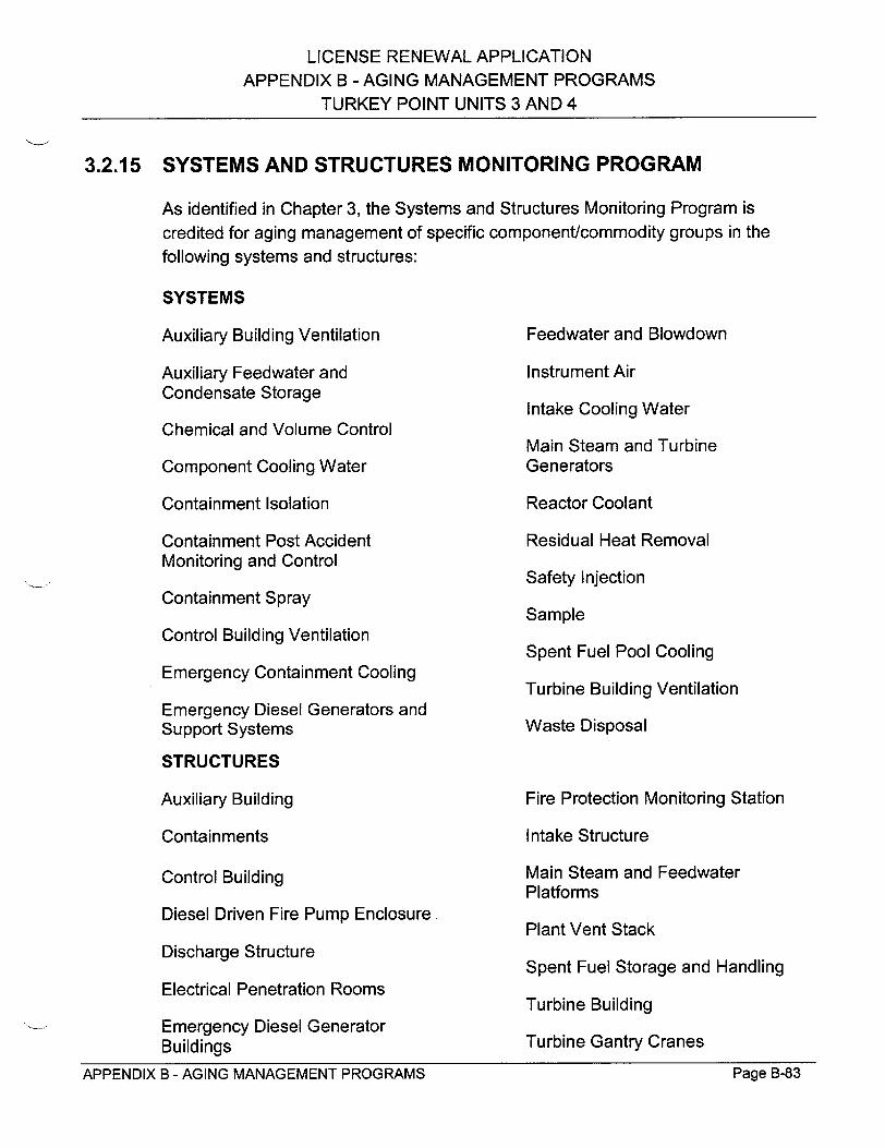
LICENSE RENEWAL APPLICATION APPENDIX B - AGING MANAGEMENT PROGRAMS
TURKEY POINT UNITS 3 AND 4
3.2.15 SYSTEMS AND STRUCTURES MONITORING PROGRAM
As identified in Chapter 3, the Systems and Structures Monitoring Program is
credited for aging management of specific component/commodity groups in the
following systems and structures:
SYSTEMS
Auxiliary Building Ventilation Feedwater and Blowdown
Auxiliary Feedwater and Instrument Air Condensate Storage
Intake Cooling Water Chemical and Volume Control
Main Steam and Turbine Component Cooling Water Generators
Containment Isolation Reactor Coolant
Containment Post Accident Residual Heat Removal Monitoring and Control
Safety Injection Containment Spray
Sample Control Building Ventilation
Spent Fuel Pool Cooling Emergency Containment Cooling
Turbine Building Ventilation Emergency Diesel Generators and Support Systems Waste Disposal
STRUCTURES
Auxiliary Building Fire Protection Monitoring Static
Containments Intake Structure
Control Building
Diesel Driven Fire Pump Enclosure
Discharge Structure
Electrical Penetration Rooms
Emergency Diesel Generator Buildings
APPENDIX B - AGING MANAGEMENT PROGRAMS
Main Steam and Feedwater
Platforms
Plant Vent Stack
Spent Fuel Storage and Handling
Turbine Building
Turbine Gantry Cranes
Page B-83
)n

LICENSE RENEWAL APPLICATION
APPENDIX B - AGING MANAGEMENT PROGRAMS
TURKEY POINT UNITS 3 AND 4
STRUCTURES (continued)
Yard Structures
Scope
The Systems and Structures Monitoring Program manages the aging effects of loss
of material, cracking, fouling, loss of seal, and change in material properties for
selected systems, structures, and components within the scope of license renewal.
The program provides for visual inspection and examination of accessible surfaces
of specific systems, structures, and components, including welds and bolting.
Aging management of structural components that are inaccessible for inspection is
accomplished by inspecting accessible structural components with similar materials
and environments for aging effects that may be indicative of aging effects for
inaccessible structural components. For example, rust bleeding on an accessible
surface of a concrete structure may be indicative of corrosion of inaccessible
reinforcing steel embedded in the concrete.
This program will be enhanced by restructuring it to address inspection requirements
to manage certain aging effects in accordance with 10 CFR 54, modifying the scope
of specific inspections, and improving documentation requirements. Commitment
dates associated with the enhancement of this program are contained in
Appendix A.
Preventive Actions
External surfaces of carbon steel and cast iron valves, piping, and fittings, and
specific stainless steel piping welds are coated to minimize corrosion and surfaces
of steel structures and supports are also coated to minimize corrosion. Coatings
minimize corrosion by limiting exposure to the environment. However, coatings are
not credited in the determination of the aging effects requiring management.
Parameters Monitored or Inspected
Surface conditions of structures, system components/piping (including those
exposed to a wetted environment), and supports are monitored through visual
examinations to determine the existence of external corrosion and internal corrosion
of certain ventilation equipment. Flexible connections are monitored for cracking
due to embrittlement and ventilation heat exchangers are monitored for fouling.
External surfaces of concrete are monitored through visual examination for exposed
Page B-84APPENDIX B - AGING MANAGEMENT PROGRAMS
LICENSE RENEWAL APPLICATION
APPENDIX B - AGING MANAGEMENT PROGRAMS TURKEY POINT UNITS 3 AND 4
rebar, extensive rust bleeding, cracks that exhibit rust bleeding, and cracking of
block walls and building roof seals. Leakage inspections of valves, piping, and
fittings at limited locations of the Intake Cooling Water and Waste Disposal Systems
are utilized to detect the presence of internal corrosion. Additionally, visual
inspection of external surfaces of certain ventilation systems is used to assess
internal system conditions. Inspection of protective coatings on specific stainless
steel piping welds in outdoor locations will be performed to determine coating
degradation. Inspection of weatherproofing material for deterioration is performed.
This program will be restructured and some enhancements to the scope of specific
inspections and their documentation will be implemented.
Detection of Aging Effects
The aging effects of loss of material, crack initiation, fouling, loss of seal, and
change in material properties are detected by visual inspection of external surfaces
(including internal surfaces of certain ventilation equipment) for evidence of
corrosion, cracking, leakage, fouling, or coatings damage.
Monitoring and Trending
Detailed structural and system/equipment material condition inspections are
performed in accordance with approved plant procedures. The results of the visual
inspections for systems, structures, and components are documented. The
frequency of the inspections may be adjusted, as necessary, based on inspection
results and industry experience. For insulated piping, a small sample of the sections
of systems exposed to a wetted environment will be selected for inspection on the
basis of piping geometry and potential exposure to rain or other conditions that could
result in wetting of the insulation (e.g., chilled water systems).
Acceptance Criteria
The results of the inspections and testing are evaluated in accordance with the
acceptance criteria in the appropriate corrective action and administrative
procedures.
Confirmation Process
Degradations are evaluated and entered into the corrective action program.
Page B-85APPENDIX B - AGING MANAGEMENT PROGRAMS

LICENSE RENEWAL APPLICATION
APPENDIX B - AGING MANAGEMENT PROGRAMS
TURKEY POINT UNITS 3 AND 4
Operating Experience and Demonstration
Systems and piping/component support material condition inspections have been
successfully performed at Turkey Point since the mid 1980s. The inspection
requirements in support of the Maintenance Rule have been in effect since 1996,
and have proven effective at maintaining systems/structures material condition and
detecting unsatisfactory conditions that have resulted in effective corrective actions
being taken.
The Systems and Structures Monitoring Program has been an ongoing program at
Turkey Point and has been enhanced over the years to include the best practices
recommended by the Institute of Nuclear Power Operations and other industry
guidance. Additionally, the Systems and Structures Monitoring Program will
continue to support implementation of the NRC Maintenance Rule (10 CFR 50.65).
The effectiveness of the Systems and Structures Monitoring Program is supported
by the improved system and structure material conditions, documented by internal
as well as external assessments of the last several years. Additionally, the Systems
and Structures Monitoring Program is the subject of periodic internal and external
assessments to insure effectiveness and continued improvement.
Based upon the above, the continued implementation of the Systems and Structures
Monitoring Program provides reasonable assurance that the aging effects (loss of
material, crack initiation, fouling, loss of seal, and change in material properties) will
be managed such that systems and structures within the scope of License Renewal
will continue to perform their intended functions consistent with the current licensing
basis for the period of extended operation.
APPENDIX B - AGING MANAGEMENT PROGRAMS Page B-56APPENDIX B - AGING MANAGEMENT PROGRAMS Page B-86

* " LICENSE RENEWAL APPLICATION
APPENDIX B - AGING MANAGEMENT PROGRAMS
TURKEY POINT UNITS 3 AND 4
3.2.16 THIMBLE TUBE INSPECTION PROGRAM
As identified in Chapter 3, the Thimble Tube Inspection Program is credited for aging
management of Unit 3 reactor vessel thimble tube N-05 in the Reactor Coolant
Systems. The program was originally performed on all in-service thimble tubes for
Units 3 and 4.
Scope
Based on previous inspections and the Time-Limited Aging Analysis results
presented in Subsection 4.7.1, only thimble tube N-05 on Unit 3 will require
inspection for the period of extended operation. The Thimble Tube Inspection
Program manages the aging effect of loss of material due to fretting wear. The
program utilizes eddy current test inspections to determine thimble tube wall
thickness and predict wear rates for the early identification of potential thimble tube
failure.
Preventive Actions
The thimble tube wall thickness obtained from eddy current test inspections will be
used to predict thimble tube wear rates and enable corrective action before the
thimble tube fails.
Parameters Monitored or Inspected
Thimble tube wall thickness.
Detection of Aging Effects
Thimble tube wall thinning will be determined utilizing eddy current testing
inspections.
Monitoring and Trending
An eddy current test inspection will be performed on Unit 3 thimble tube N-05 in
accordance with plant procedures. The data obtained from this inspection will be
evaluated and the need for additional inspections will be determined.
APPENDIX B - AGING MANAGEMENT PROGRAMS Page �-�j(Page B-87APPENDIX B - AGING MANAGEMENT PROGRAMS
LICENSE RENEWAL APPLICATION
APPENDIX B - AGING MANAGEMENT PROGRAMS
TURKEY POINT UNITS 3 AND 4
Acceptance Criteria
The acceptance criteria for thimble tube wall thinning is less than 70% wall loss at
the end of life.
Confirmation Process
Follow-up testing is performed to confirm satisfactory completion of corrective
actions, if needed.
Operating Experience and Demonstration
The Thimble Tube Inspection Program was created and implemented in response to
NRC Bulletin 88-09, "Thimble Tube Thinning in Westinghouse Reactors" [Reference
B-18]. This program has proven experience in addressing the requirements of the
bulletin.
Wear of the thimble tubes is detected by the eddy current inspection. This technique
is well known in the industry and has been used to detect imperfections in thimble
tubes and other component tubing, such as steam generators, heat exchangers, etc.
The eddy current inspection technique has been used to detect wall thinning on the
thimble tubes with satisfactory results. The eddy current test inspection is performed
in accordance with approved plant procedures by qualified personnel.
Based on the above, the implementation of the Thimble Tube Inspection Program
provides reasonable assurance that the aging effects will be managed such that the thimble tubes will continue to perform their intended functions consistent with the
current licensing basis for the period of extended operation.
APPENDIX B - AGING MANAGEMENT PROGRAMS Page B-88Page B-88APPENDIX B - AGING MANAGEMENT PROGRAMS
LICENSE RENEWAL APPLICATION
APPENDIX B - AGING MANAGEMENT PROGRAMS
TURKEY POINT UNITS 3 AND 4
4.0 REFERENCES
B-1 "Standard Review Plan for the Review of License Renewal Applications for
Nuclear Power Plants," draft, U.S. Nuclear Regulatory Commission,
April 21, 2000.
B-2 NEI 95-10, Revision 1, "Industry Guidelines for Implementing the
Requirements of 10 CFR Part 54 - The License Renewal Rule," Nuclear
Energy Institute, January 2000.
B-3 FPL Letter, L-2000-010 to NRC, Turkey Point Unit 3, Docket No. 50-250,
"Risk Informed Inservice Inspection Program," January 19, 2000.
B-4 Third Interval Inservice Inspection Program for Turkey Point Nuclear Units 3
and 4, ISI-PTN-3/4 Program, Revision 3, Turkey Point Nuclear Power Plants,
Florida Power & Light Company, March 31, 1995.
B-5 Safety Evaluation by the Office of Nuclear Reactor Regulation Related to the
Third Ten-Year Interval Inservice Inspection Program Plan and Associated
Requests for Relief," U. S. Nuclear Regulatory Commission, March 31, 1995.
B-6 NEI 94-01, "Industry Guidelines for Implementing Performance-Based
Options of 10 CFR Part 50, Appendix J," Nuclear Energy Institute, July 26,
1995.
B-7 Regulatory Guide 1.35, Revision 3, "Inservice Inspection of Ungrouted
Tendons in Prestressed Concrete Containments," U.S. Nuclear Regulatory
Commission, April 19,1979.
B-8 Generic Letter 88-05, "Boric Acid Corrosion of Carbon Steel Reactor Pressure
Boundary Components in PWR Plants," U.S. Nuclear Regulatory
Commission, March 17,1988.
B-9 R. J. Hovey (FPL) letter to U. S. Nuclear Regulatory Commission, "Response
to Generic Letter 96-04 - Boraflex Degradation in Spent Fuel Pool Storage
Racks," October 18, 1996.
B-10 Generic Letter 89-08, "Erosion/Corrosion-Induced Pipe Wall Thinning," U.S.
Nuclear Regulatory Commission, May 1989.
APPENDIX B - AGING MANAGEMENT PROGRAMS Page E5-89

LICENSE RENEWAL APPLICATION
APPENDIX B - AGING MANAGEMENT PROGRAMS
TURKEY POINT UNITS 3 AND 4
B-11 Generic Letter 89-13, "Service Water System Problems Affecting Safety
Related Equipment," U.S. Nuclear Regulatory Commission, July 1989.
B-12 Generic Letter 97-01, "Degradation of Control Rod Drive Mechanism Nozzle
and Other Vessel Closure Head Penetrations," U.S. Nuclear Regulatory
Commission, April 1997.
B-13 David J. Modeen, (NEI) letter to Gus C. Lainas (NRC), "Response to NRC
Request for Additional Information on Generic Letter 97-01, Project Number
689," December 11, 1998.
B-14 K. N. Jabbour (NRC) letter to T. F. Plunkett (FPL), "Generic Letter 97-01,
Degradation of Control Rod Drive Mechanical Nozzle and Other Vessel
Closure Head Penetrations: Review of the Responses for the Turkey Point
Plant, Units 3 and 4," January 27, 2000.
B-1 5 Regulatory Guide 1.99, Revision 2, "Radiation Embrittlement of Reactor
Vessel Materials," U.S. Nuclear Regulatory Commission, February 1986.
B-16 Draft Regulatory Guide DG-1053, "Calculational and Dosimetry Methods for
Determining Pressure Vessel Neutron Fluence," U.S. Nuclear Regulatory
Commission, June 1996.
B-17 NEI 97-06, "Steam Generator Program Guidelines," Nuclear Energy Institute,
November 1997.
B-18 Bulletin 88-09, "Thimble Tube Thinning in Westinghouse Reactors," U.S.
Nuclear Regulatory Commission, July 26, 1988.
APPENDIX B - AGING MANAGEMENT PROGRAMS h'age b-�UPage B-90APPENDIX B - AGING MANAGEMENT PROGRAMS
LICENSE RENEWAL APPLICATION
APPENDIX C - PROCESS FOR IDENTIFYING AGING EFFECTS REQUIRING
MANAGEMENT FOR NON-CLASS 1 COMPONENTS
TURKEY POINT UNITS 3 AND 4
APPENDIX C
PROCESS FOR IDENTIFYING AGING EFFECTS REQUIRING
MANAGEMENT FOR
NON-CLASS 1 COMPONENTS
Page C-1APPENDIX C - PROCESS FOR IDENTIFYING AGING EFFECTS REQUIRING MANAGEMENT FOR NON-CLASS 1 COMPONENTS
LICENSE RENEWAL APPLICATION
APPENDIX C - PROCESS FOR IDENTIFYING AGING EFFECTS REQUIRING
MANAGEMENT FOR NON-CLASS 1 COMPONENTS TURKEY POINT UNITS 3 AND 4
TABLE OF CONTENTS
1 .0 IN T R O D U C T IO N ................................................................................................ C -7
2.0 COMPONENTS SUBJECT TO AN AGING MANAGEMENT R E V IE W ............................................................................................................. C -9
3.0 MATERIALS USED IN NON-CLASS 1 COMPONENTS ......... c-lo
4.0 ENVIRONMENTS ...................................................................................... c-11
4.1 INTERNAL ENVIRONMENTS ....................................................................... C-11 4.1.1 TREATED W ATER ............................................................................ C-11 4.1.2 RAW W ATER .................................................................................... C-11 4 .1.3 A IR /G A S ................................................................................................. C -12
4 .1.4 F U E L O IL ................................................................................................ C -12
4.1.5 LU B R IC A TIN G O IL ................................................................................. C -12
4.2 EXTERNAL ENVIRONM ENTS .......................................................................... C-13
4 .2 .1 O U T D O O R ............................................................................................. C -13
4.2.2 INDOOR - NOT AIR CONDITIONED ..................................................... C-13
4.2.3 INDOOR - AIR CONDITIONED ............................................................. C-13
4.2.4 C O NTA IN M ENT A IR .............................................................................. C-13
4.2.5 BORATED WATER LEAKS .................................................................... C-14
4 .2 .6 B U R IE D .................................................................................................. C -14
4.2.7 EM BEDDED/ENCASED ......................................................................... C-14
5.0 POTENTIAL AGING EFFECTS .......................................................... C-15
5.1 LO SS O F M ATERIAL ................................................................................... C-15 5 .2 C R A C K IN G ....................................................................................................... C -18
5 .3 F O U L IN G .......................................................................................................... C -2 0
5.4 LOSS OF MECHANICAL CLOSURE INTEGRITY ............................................ C-21
5.5 REDUCTION IN FRACTURE TOUGHNESS .................................................... C-22
5.6 DISTORTION/PLASTIC DEFORMATION ......................................................... C-22
APPENDIX C - PROCESS FOR IDENTIFYING AGING EFFECTS REQUIRING Page C-2 MANAGEMENT FOR NON-CLASS 1 COMPONENTS

LICENSE RENEWAL APPLICATION
APPENDIX C - PROCESS FOR IDENTIFYING AGING EFFECTS REQUIRING
MANAGEMENT FOR NON-CLASS 1 COMPONENTS TURKEY POINT UNITS 3 AND 4
6.0 AGING EFFECTS REQUIRING MANAGEMENT FOR
INTERNAL ENVIRONMENTS ................................................................... C-24
6.1 TR EAT ED W ATER ............................................................................................ C -24
6.1.1 ATTRIBUTES OF TREATED WATER ENVIRONMENTS ...................... C-24
6.1.2 MATERIALS USED IN TREATED WATER ENVIRONMENTS .............. C-25
6.1.3 AGING EFFECTS IN TREATED WATER ENVIRONMENTS ................. C-25
6.1.3.1 LOSS OF MATERIAL ................................................................ C-25
6.1.3.2 C RA C K IN G ............................................................................... C -26
6 .1.3.3 FO U LIN G .................................................................................. C -26
6.1.4 INDUSTRY EXPERIENCE WITH TREATED WATER
E NV IR O N M E NTS ................................................................................... C -26
6.2 R A W W A T E R .................................................................................................... C -27
6.2.1 ATTRIBUTES OF RAW WATER ENVIRONMENTS .............................. C-27
6.2.2 MATERIALS USED IN RAW WATER ENVIRONMENTS ....................... C-27
6.2.3 AGING EFFECTS IN RAW WATER ENVIRONMENTS ......................... C-27
6.2.3.1 LOSS OF MATERIAL ................................................................ C-27
6.2.3.2 C RA C K IN G ............................................................................... C -28
6.2.3.3 FO U LIN G .................................................................................. C -28
6.2.4 INDUSTRY EXPERIENCE WITH RAW WATER ENVIRONMENTS ...... C-28
6 .3 A IR /G A S ............................................................................................................ C -2 9
6.3.1 ATTRIBUTES OF AN AIR/GAS ENVIRONMENT ................................... C-29
6 .3 .1.1 A IR ............................................................................................ C -2 9
6.3.1.2 N IT R O G E N ............................................................................... C -29
6.3.1.3 CARBO N DIO XIDE ................................................................... C-29 6.3.1.4 HY D R O G EN .............................................................................. C -29
6 .3 .1.5 H A LO N ...................................................................................... C -30
6.3.2 MATERIALS USED IN AN AIR/GAS ENVIRONMENT ........................... C-30
6.3.3 AGING EFFECTS IN AN AIR/GAS ENVIRONMENT ............................. C-30
6.3.3.1 LOSS OF MATERIAL ................................................................ C-30
6.3.3.2 C RA C K IN G ............................................................................... C -31
6.3.4 INDUSTRY EXPERIENCE WITH AIR/GAS ENVIRONMENT ................ C-31
6 .4 F U E L O IL .......................................................................................................... C -3 2
6.4.1 ATTRIBUTES OF A FUEL OIL ENVIRONMENT .................................... C-32
6.4.2 MATERIALS USED IN A FUEL OIL ENVIRONMENT ............................ C-32
6.4.3 AGING EFFECTS IN A FUEL OIL ENVIRONMENT ............................... C-32
APPENDIX C - PROCESS FOR IDENTIFYING AGING EFFECTS REQUIRING Page C-3 MANAGEMENT FOR NON-CLASS 1 COMPONENTS

LICENSE RENEWAL APPLICATION
APPENDIX C - PROCESS FOR IDENTIFYING AGING EFFECTS REQUIRING
MANAGEMENT FOR NON-CLASS 1 COMPONENTS
TURKEY POINT UNITS 3 AND 4
6.4.3.1 LOSS O F MATERIAL ................................................................ C-32 6.4.4 INDUSTRY EXPERIENCE WITH A FUEL OIL ENVIRONMENT ........... C-33
6.5 LU B R ICA T IN G O IL ........................................................................................... C -34
6.5.1 ATTRIBUTES OF A LUBRICATING OIL ENVIRONMENT ..................... C-34 6.5.2 MATERIALS USED IN A LUBRICATING OIL ENVIRONMENT ............. C-34
6.5.3 AGING EFFECTS IN A LUBRICATING OIL ENVIRONMENT ................ C-34
6.5.4 INDUSTRY EXPERIENCE WITH A LUBRICATING OIL
E N V IR O N M E N T ..................................................................................... C -34
7.0 AGING EFFECTS REQUIRING MANAGEMENT FOR EXTERNAL ENVIRONMENTS ................................................................. C-35
7 .1 O U T D O O R ........................................................................................................ C -35 7.1.1 ATTRIBUTES OF AN OUTDOOR ENVIRONMENT ............................... C-35
7.1.2 MATERIALS USED IN AN OUTDOOR ENVIRONMENT ....................... C-35
7.1.3 AGING EFFECTS IN AN OUTDOOR ENVIRONMENT .......................... C-35 7.1.3.1 LO SS O F M ATERIAL ................................................................ C-35
7.1.3.2 C RA C K IN G ............................................................................... C -36 7.1.3.3 FO U LIN G .................................................................................. C -36
7.1.4 INDUSTRY EXPERIENCE WITH AN OUTDOOR ENVIRONMENT ....... C-36 7.2 INDOOR - NOT AIR CONDITIONED ................................................................ C-37
7.2.1 ATTRIBUTES OF AN INDOOR - NOT AIR CONDITIONED E NV IR O N M E N T ..................................................................................... C -37
7.2.2 MATERIALS USED IN AN INDOOR - NOT AIR CONDITIONED E N V IR O N M E N T ..................................................................................... C -37
7.2.3 AGING EFFECTS IN AN INDOOR - NOT AIR CONDITIONED
E N V IR O N M E N T ..................................................................................... C -37 7.2.3.1 LOSS O F MATERIAL ................................................................ C-37 7.2.3.2 C RA C KIN G ............................................................................... C -38
7.2.4 INDUSTRY EXPERIENCE WITH AN INDOOR - NOT AIR
CONDITIONED ENVIRONMENT ........................................................... C-38 7.3 INDOOR - AIR CO NDITIONED ........................................................................ C-39
7.3.1 ATTRIBUTES OF AN INDOOR - AIR CONDITIONED E N V IR O N M E N T ..................................................................................... C -39
7.3.2 MATERIALS USED IN AN INDOOR -AIR CONDITIONED E N V IR O N M E N T ..................................................................................... C -39
APPENDIX C - PROCESS FOR IDENTIFYING AGING EFFECTS REQUIRING Page C-4 MANAGEMENT FOR NON-CLASS 1 COMPONENTS

LICENSE RENEWAL APPLICATION APPENDIX C - PROCESS FOR IDENTIFYING AGING EFFECTS REQUIRING
MANAGEMENT FOR NON-CLASS 1 COMPONENTS TURKEY POINT UNITS 3 AND 4
7.3.3 AGING EFFECTS IN AN INDOOR - AIR-CONDITIONED E N V IR O N M E N T ..................................................................................... C -39 7.3.3.1 LOSS O F MATERIAL ................................................................ C-39 7.3.3.2 C RA C K IN G ............................................................................... C -40
7.3.4 INDUSTRY EXPERIENCE WITH AN INDOOR - AIR CONDITIONED E N V IR O N M E N T ..................................................................................... C -40
7.4 C O NTA IN M ENT A IR ......................................................................................... C -41 7.4.1 ATTRIBUTES OF A CONTAINMENT AIR ENVIRONMENT .................. C-41 7.4.2 MATERIALS USED IN A CONTAINMENT AIR ENVIRONMENT ........... C-41 7.4.3 AGING EFFECTS IN A CONTAINMENT AIR ENVIRONMENT ............. C-41
7.4.3.1 LO SS O F M ATERIAL ................................................................ C-41 7.4.3.2 C RA C K IN G ............................................................................... C -42 7.4.3.3 FO U LIN G .................................................................................. C -42
7.4.4 INDUSTRY EXPERIENCE WITH A CONTAINMENT AIR ENV IRO NM ENT ................................................................................ C-42
7.5 BO RATED W ATER LEAKS ............................................................................... C-43 7.5.1 ATTRIBUTES OF A BORATED WATER LEAKS ENVIRONMENT ........ C-43 7.5.2 MATERIALS USED IN A BORATED WATER LEAKS
E NV IR O N M ENT ..................................................................................... C -43 7.5.3 AGING EFFECTS IN A BORATED WATER LEAKS ENVIRONMENT... C-43
7.5.3.1 LO SS O F MATERIAL ................................................................ C-43 7.5.3.2 LOSS OF MECHANICAL CLOSURE INTEGRITY .................... C-43
7.5.4 INDUSTRY EXPERIENCE WITH A BORATED WATER LEAKS E N V IR O N M E N T ..................................................................................... C -44
7 .6 B U R IE D ............................................................................................................. C -4 5 7.6.1 ATTRIBUTES OF A BURIED ENVIRONMENT ...................................... C-45 7.6.2 MATERIALS USED IN A BURIED ENVIRONMENT .............. C-45 7.6.3 AGING EFFECTS IN A BURIED ENVIRONMENT ................................. C-45
7.6.3.1 LO SS O F MATERIAL ................................................................ C-45 7.6.4 INDUSTRY EXPERIENCE WITH A BURIED ENVIRONMENT .............. C-46
7.7 EM BEDDED/ENCASED .................................................................................... C-47 7.7.1 ATTRIBUTES OF AN EMBEDDED/ENCASED ENVIRONMENT .......... C-47 7.7.2 MATERIALS USED IN AN EMBEDDED/ENCASED ENVIRONMENT... C-47 7.7.3 AGING EFFECTS IN AN EMBEDDED/ENCASED ENVIRONMENT ..... C-47 7.7.4 INDUSTRY EXPERIENCE WITH AN EMBEDDED/ENCASED
E NV IR O N M E N T ..................................................................................... C -47
APPENDIX C - PROCESS FOR IDENTIFYING AGING EFFECTS REQUIRING Page C-5
MANAGEMENT FOR NON-CLASS 1 COMPONENTS

LICENSE RENEWAL APPLICATION APPENDIX C - PROCESS FOR IDENTIFYING AGING EFFECTS REQUIRING
MANAGEMENT FOR NON-CLASS 1 COMPONENTS TURKEY POINT UNITS 3 AND 4
8 .0 R E F E R E N C E S ................................................................................................... C -4 8
APPENDIX C - PROCESS FOR IDENTIFYING AGING EFFECTS REQUIRING Page C-6 MANAGEMENT FOR NON-CLASS 1 COMPONENTS
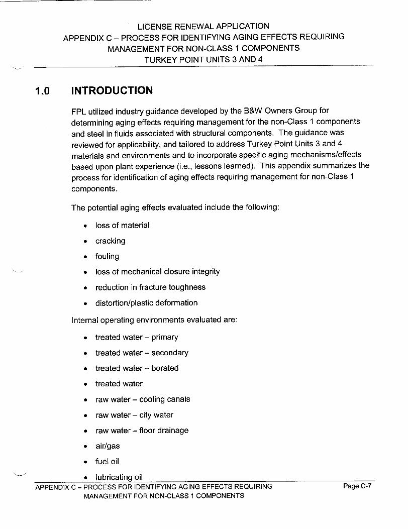
LICENSE RENEWAL APPLICATION
APPENDIX C - PROCESS FOR IDENTIFYING AGING EFFECTS REQUIRING
MANAGEMENT FOR NON-CLASS 1 COMPONENTS
TURKEY POINT UNITS 3 AND 4
1.0 INTRODUCTION
FPL utilized industry guidance developed by the B&W Owners Group for
determining aging effects requiring management for the non-Class 1 components
and steel in fluids associated with structural components. The guidance was
reviewed for applicability, and tailored to address Turkey Point Units 3 and 4
materials and environments and to incorporate specific aging mechanisms/effects
based upon plant experience (i.e., lessons learned). This appendix summarizes the
process for identification of aging effects requiring management for non-Class 1
components.
The potential aging effects evaluated include the following:
"* loss of material
"* cracking
"* fouling
"* loss of mechanical closure integrity
"* reduction in fracture toughness
"* distortion/plastic deformation
Internal operating environments evaluated are:
"* treated water - primary
"* treated water - secondary
"* treated water - borated
"* treated water
"* raw water - cooling canals
"* raw water - city water
"* raw water - floor drainage
"* air/gas
"* fuel oil
"* lubricating oil APPENDIX C - PROCESS FOR IDENTIFYING AGING EFFECTS REQUIRING Page C-7
MANAGEMENT FOR NON-CLASS 1 COMPONENTS
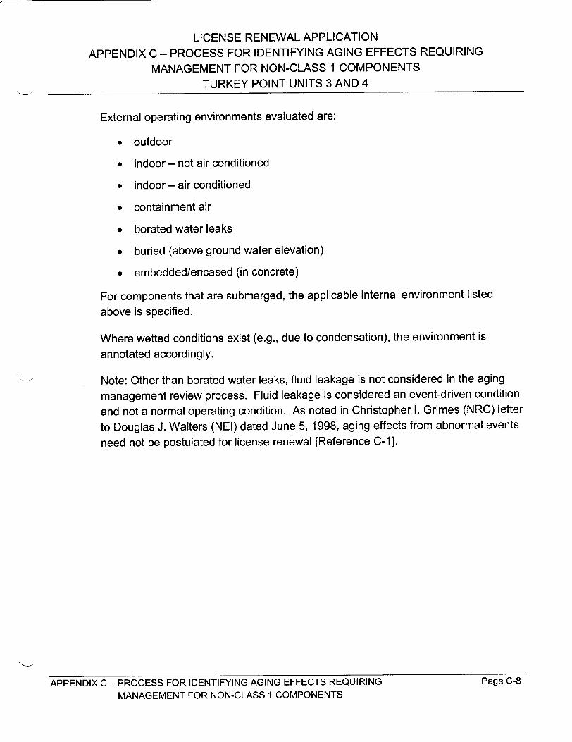
LICENSE RENEWAL APPLICATION
APPENDIX C - PROCESS FOR IDENTIFYING AGING EFFECTS REQUIRING
MANAGEMENT FOR NON-CLASS 1 COMPONENTS
TURKEY POINT UNITS 3 AND 4
External operating environments evaluated are:
"* outdoor
"* indoor - not air conditioned
"* indoor - air conditioned
"* containment air
"* borated water leaks
"* buried (above ground water elevation)
"* embedded/encased (in concrete)
For components that are submerged, the applicable internal environment listed
above is specified.
Where wetted conditions exist (e.g., due to condensation), the environment is
annotated accordingly.
Note: Other than borated water leaks, fluid leakage is not considered in the aging
management review process. Fluid leakage is considered an event-driven condition
and not a normal operating condition. As noted in Christopher I. Grimes (NRC) letter
to Douglas J. Walters (NEI) dated June 5, 1998, aging effects from abnormal events
need not be postulated for license renewal [Reference C-1].
APPENDIX C - PROCESS FOR IDENTIFYING AGING EFFECTS REQUIRING Page C-8
MANAGEMENT FOR NON-CLASS 1 COMPONENTS
LICENSE RENEWAL APPLICATION
APPENDIX C - PROCESS FOR IDENTIFYING AGING EFFECTS REQUIRING
MANAGEMENT FOR NON-CLASS 1 COMPONENTS
TURKEY POINT UNITS 3 AND 4
2.0 COMPONENTS SUBJECT TO AN AGING MANAGEMENT
REVIEW
In accordance with 10 CFR 54 and NEI 95-10, "Industry Guidelines for Implementing
the Requirements of 10 CFR Part 54 - The License Renewal Rule," Appendix B
[Reference C-2], only passive components are in the scope of review. Within the
systems that are in the scope of license renewal, the following are typical
components subject to aging management review:
ductwork heat exchangers pump casings
expansion joints mechanical closure steam traps bolting
flexible hoses orifices and flow tanks/vessels elements
filters, strainers and piping, tubing, and valve bodies and housings fittings bonnets
fuel handling equipment fuel storage racks
Many of the components within the scope of license renewal contain gaskets,
packing, and seals. However, these items, defined as consumables [Reference
C-3], are not subject to aging management review since they do not support the
component intended functions as established by design codes and are not long
lived.
APPENDIX C - PROCESS FOR IDENTIFYING AGING EFFECTS REQUIRING Page C-9
MANAGEMENT FOR NON-CLASS 1 COMPONENTS
LICENSE RENEWAL APPLICATION
APPENDIX C - PROCESS FOR IDENTIFYING AGING EFFECTS REQUIRING
MANAGEMENT FOR NON-CLASS 1 COMPONENTS
TURKEY POINT UNITS 3 AND 4
MATERIALS USED IN NON-CLASS 1 COMPONENTS
The following materials are present in non-Class 1 systems within the scope of
license renewal:
aluminum aluminum alloys
carbon steel (plain and galvanized)
cast iron (ductile, white, malleable)
gray cast iron
coated canvas copper copper alloys (admiralty brass, red brass, copper nickel, bronze, aluminum brass, aluminum bronze) Inconel (alloy 600)
low alloy steel
Monel neoprene rubber
stainless steel (wrought and cast) Worthite (nickel based alloy)
Note that some components contain internal and external coatings or linings. For
example, Intake Cooling Water piping is cement lined and some valves are rubber
lined. These features perform a preventive function, but are not credited for the
elimination of aging effects requiring management.
Page C-10
3.0
APPENDIX C - PROCESS FOR IDENTIFYING AGING EFFECTS REQUIRING
MANAGEMENT FOR NON-CLASS 1 COMPONENTS
LICENSE RENEWAL APPLICATION
APPENDIX C - PROCESS FOR IDENTIFYING AGING EFFECTS REQUIRING
MANAGEMENT FOR NON-CLASS 1 COMPONENTS
TURKEY POINT UNITS 3 AND 4
4.0 ENVIRONMENTS
4.1 INTERNAL ENVIRONMENTS
4.1.1 TREATED WATER
Treated water is demineralized water and is the base water for all clean systems.
Depending on the system, treated water may involve additional processing. Treated
water can be deaerated, and can include corrosion inhibitors, biocides, boric acid, or
a combination of these treatments. Within this Application, treated water has been
subdivided into groups based on the chemistry of the water.
"* Treated water - primary - Normal operating Reactor Coolant System
chemistry
"• Treated water - secondar - Normal operating secondary chemistry,
including Main Steam, Feedwater, and Blowdown Systems
"* Treated water - borated - Systems that contain borated water except those
included in treated water - primary, including Chemical and Volume Control,
Spent Fuel Cooling, and Emergency Core Cooling Systems
"* Treated water - All other treated water systems, including Component
Cooling Water, Emergency Diesel Generator Cooling, and Chilled Water
Systems. These systems utilize corrosion inhibitors and, in some cases,
biocides.
Aging effects for materials typically found in treated water environments are
summarized in Section 6.1 of this appendix.
4.1.2 RAW WATER
For Turkey Point, raw water constitutes the salt water that comes from a closed
cooling water canal system and is used for the main condensers and Intake Cooling
Water System, and the city water used for the Fire Protection System. In general,
the water has been rough filtered to remove large particles and may contain a
biocide additive for control of micro-organisms and macro-organisms. Although city
water is purified, it is conservatively classified as raw water for the purposes of aging
APPENDIX C - PROCESS FOR IDENTIFYING AGING EFFECTS REQUIRING Page C-11
MANAGEMENT FOR NON-CLASS 1 COMPONENTS

LICENSE RENEWAL APPLICATION
APPENDIX C - PROCESS FOR IDENTIFYING AGING EFFECTS REQUIRING
MANAGEMENT FOR NON-CLASS 1 COMPONENTS
TURKEY POINT UNITS 3 AND 4
management review. Within this Application, raw water has been subdivided into
groups based on the chemistry of the water.
"* Raw water - cooling canals - Salt water used as the ultimate heat sink
"* Raw water - city water - Potable water supplied to the water treatment plant
and the Fire Protection System
" Raw water - floor draina-ge - Fluids collected in building drains. The fluids
can be treated water (primary, secondary, borated, or other), raw water
(cooling canals or city water), fuel oil, or lubricating oil
Aging effects for materials typically found in raw water environments are
summarized in Section 6.2 of this appendix.
4.1.3 AIRIGAS
This includes atmospheric air, dry/filtered instrument air, nitrogen, carbon dioxide,
hydrogen, helium, and Halon. Aging effects for materials typically found in air/gas
environments are summarized in Section 6.3 of this appendix. Where wetted
conditions are determined to exist (e.g., due to condensation), the environment
description is amended accordingly, and potential aging effects are addressed.
4.1.4 FUEL OIL
This includes fuel oil for the emergency diesel generators, diesel fire pump, and
standby steam generator feedwater pump. Aging effects for materials typically
found in fuel oil environments are summarized in Section 6.4 of this appendix.
4.1.5 LUBRICATING OIL
This environment is the lubricating oil for emergency diesel generators, pumps, and
other components. Aging effects for materials typically found in lubricating oil
environments are summarized in Section 6.5 of this appendix.
APPENDIX C - PROCESS FOR IDENTIFYING AGING EFFECTS REQUIRING Page C-12 MANAGEMENT FOR NON-CLASS 1 COMPONENTS
LICENSE RENEWAL APPLICATION
APPENDIX C - PROCESS FOR IDENTIFYING AGING EFFECTS REQUIRING
MANAGEMENT FOR NON-CLASS 1 COMPONENTS
TURKEY POINT UNITS 3 AND 4
4.2 EXTERNAL ENVIRONMENTS
4.2.1 OUTDOOR
The outdoor environment is characterized by moist, salt laden atmospheric air,
temperature 30°F-950F, humidity 5%-95%, and exposure to weather, including
precipitation and wind. Aging effects for materials typically found in outdoor
environments are summarized in Section 7.1 of this appendix.
4.2.2 INDOOR - NOT AIR CONDITIONED
This includes atmospheric air, a temperature of 1040F maximum , humidity 5%-95%,
no exposure to weather. Aging effects for materials typically found in indoor - not air
conditioned environments are summarized in Section 7.2 of this appendix.
4.2.3 INDOOR - AIR CONDITIONED
This includes atmospheric air with a specific temperature/humidity range dependent
upon the building/room, and involves no exposure to weather. Typically, the
temperature is 700F, and the humidity is 60%-80%. Aging effects for materials
typically found in indoor - air conditioned environments are summarized in Section
7.3 of this appendix.
4.2.4 CONTAINMENT AIR
This includes atmospheric air, a temperature of 120OF maximum, humidity 5%-95%,
radiation - total integrated dose rate 1 rad per hour (excluding equipment located
inside the reactor cavity), and no exposure to weather. Aging effects for materials
typically found in containment air environments are summarized in Section 7.4 of
this appendix.
Note: Safety-related equipment in the Containment has been analyzed to 1220F
continuous and 1250F for 2 weeks/year.
APPENDIX C - PROCESS FOR IDENTIFYING AGING EFFECTS REQUIRING Page C-13
MANAGEMENT FOR NON-CLASS 1 COMPONENTS

LICENSE RENEWAL APPLICATION
APPENDIX C - PROCESS FOR IDENTIFYING AGING EFFECTS REQUIRING MANAGEMENT FOR NON-CLASS 1 COMPONENTS
TURKEY POINT UNITS 3 AND 4
4.2.5 BORATED WATER LEAKS
This environment includes exposure to leakage from borated water systems. Aging
effects for materials exposed to borated water leak environments are summarized in
Section 7.5 of this appendix.
4.2.6 BURIED
Above groundwater elevation, this environment involves exposure to soil/fill. Below
groundwater elevation, this environment involves exposure to soil/fill and
groundwater. Groundwater contains aggressive chemicals that can attack
susceptible materials. Although all buried piping and mechanical components are
above groundwater elevation, buried components are assumed to be susceptible to
corrosion. Aging effects for materials typically found in buried environments are
summarized in Section 7.6 of this appendix.
4.2.7 EMBEDDED/ENCASED
This environment is associated with reinforcing or embedded steel or piping in
concrete. Aging effects for materials typically found in embedded/encased
environments are summarized in Section 7.7 of this appendix.
APPENDIX C - PROCESS FOR IDENTIFYING AGING EFFECTS REQUIRING Page C-14
MANAGEMENT FOR NON-CLASS 1 COMPONENTS

LICENSE RENEWAL APPLICATION
APPENDIX C - PROCESS FOR IDENTIFYING AGING EFFECTS REQUIRING
MANAGEMENT FOR NON-CLASS 1 COMPONENTS
TURKEY POINT UNITS 3 AND 4
5.0 POTENTIAL AGING EFFECTS
Potential aging effects were determined based on materials and environments.
Aging effects are considered to require management if the effects could cause loss
of component intended function during the period of extended operation. The
potential aging effects and associated mechanisms evaluated for non-Class 1
components are as follows.
5.1 LOSS OF MATERIAL
Loss of material may be due to general corrosion, pitting corrosion, galvanic
corrosion, crevice corrosion, erosion/corrosion, microbiologically influenced
corrosion, selective leaching, wear, and aggressive chemical attack.
General corrosion is the result of a chemical or electrochemical reaction between the
material and the environment when both oxygen and moisture are present. General
corrosion is characterized by uniform attack resulting in material dissolution and,
sometimes corrosion product buildup. General corrosion on components exposed to
air tends to form a protective oxide film on the component that prevents further
significant corrosion. This is typically true for components not exposed to other
sources of moisture such as rain, condensation, or frequent leakage. Wrought
austenitic stainless steel, copper, copper alloys, cast austenitic stainless steel
(CASS), and nickel-based alloys are not susceptible to general corrosion except
when subjected to aggressive environments. Carbon and low alloy steels are
susceptible to external general corrosion in all areas with the exception of those
exposed to a controlled, air-conditioned environment, and those applications where
the metal temperature is greater than 212 0F. Additionally, galvanized carbon steel is
not considered susceptible to general corrosion except where buried, submerged in
fluid, or subject to wetting, such as salt spray, other than humidity.
Pitting corrosion is a form of localized attack that results in depressions in the metal.
For treated water systems, oxygen is required for initiation of pitting corrosion with
contaminants, such as halogens or sulfates, required for continued metal dissolution.
Pitting corrosion occurs when passive films in local areas attack passive materials.
Once a pit penetrates the passive film, galvanic conditions occur because the metal
in this pit is anodic relative to the passive film. Maintaining adequate flow rate over
this exposed surface of a component can inhibit pitting corrosion. However,
APPENDIX C - PROCESS FOR IDENTIFYING AGING EFFECTS REQUIRING Page C-15
MANAGEMENT FOR NON-CLASS 1 COMPONENTS

LICENSE RENEWAL APPLICATION
APPENDIX C - PROCESS FOR IDENTIFYING AGING EFFECTS REQUIRING
MANAGEMENT FOR NON-CLASS 1 COMPONENTS
TURKEY POINT UNITS 3 AND 4
stagnant or low flow conditions are assumed to exist in all systems where dead legs
of piping, such as vents or drains, exist. Pitting corrosion is more common with
passive materials, such as austenitic stainless steels, than with non-passive
materials. Most materials of interest are susceptible to pitting corrosion under
certain conditions. For treated water environments, stainless and carbon steels are
assumed susceptible to pitting in the presence of halogens in excess of 150 ppb or
sulfates in excess of 100 ppb when dissolved oxygen is in excess of 100 ppb.
However, like general corrosion, moisture must be present, and those metals
exposed to a controlled, air-conditioned environment or an operating temperature
greater than 2121F are not susceptible to external pitting corrosion. Because pitting
of stainless steel material in an outdoor environment at Turkey Point is dependent
on its location within the plant site, these materials were evaluated based upon
experience and visual inspections. Typically, stainless steel materials located near
the plant discharge canal are more susceptible due to the salt spray environment.
Additionally, bronze and brass are considered susceptible to pitting when the zinc
content is greater than 15%, and aluminum bronze is considered susceptible to
pitting when the aluminum content is greater than 8%.
Loss of material due to galvanic corrosion can occur only when materials with
different electrochemical potentials are in contact within an aqueous environment.
Generally, the effects of galvanic corrosion are precluded by design (e.g., isolation to
prevent electrolytic connection or using similar materials). In galvanic couples
involving brass, carbon steel, cast iron, copper, and stainless steel materials, the
lower potential (more anodic) carbon steel, cast iron, and low-alloy steel would be
preferentially attacked.
Crevice corrosion occurs when a crevice or area of stagnant or low flow exists that
allows a corrosive environment to develop in a component. It occurs most
frequently in joints and connections, or points of contact between metals and non
metals, such as gasket surfaces, lap joints, and under bolt heads. Crevice corrosion
is strongly dependent on the presence of dissolved oxygen. For environments with
extremely low oxygen content (less than 0.1 ppm), crevice corrosion is considered
insignificant. Carbon steel, cast iron, low alloy steels, stainless steel, copper, and
nickel base alloys are all susceptible to crevice corrosion. However, experience at
Turkey Point shows that crevice corrosion is not a significant aging mechanism for
components subjected to treated water.
APPENDIX C - PROCESS FOR IDENTIFYING AGING EFFECTS REQUIRING Page C-16 MANAGEMENT FOR NON-CLASS 1 COMPONENTS
LICENSE RENEWAL APPLICATION
APPENDIX C - PROCESS FOR IDENTIFYING AGING EFFECTS REQUIRING
MANAGEMENT FOR NON-CLASS 1 COMPONENTS
TURKEY POINT UNITS 3 AND 4
Erosion is a mechanical action of fluid and/or particulate matter on a metal surface,
without the influence of corrosion. Equipment exposed to moving fluids is vulnerable
to erosion. These include piping, valves, vanes, impellers, etc. General erosion
occurs under high velocity conditions, turbulence, and impingement. Geometric
factors are extremely important. Typical forms of erosion include liquid
impingement, flashing, and cavitation. Systems and components are designed to
preclude these mechanisms. Additionally, these mechanisms are quite severe and
would typically be discovered early in a component's life. In general, erosion
mechanisms are not considered aging effects requiring management during the
period of extended operation.
Erosion/corrosion occurs when fluid or particulate is also corrosive. Erosion/
corrosion is influenced by 1) fluid flow velocity, 2) geometry, 3) environmental
characteristics (temperature and fluid chemistry), and 4) material susceptibility.
Carbon and low alloy steels are most susceptible to erosion/corrosion. Higher alloy
steels, nickel based alloys, and stainless steels are considered resistant to both
erosion and erosion/corrosion. Most of the treated water systems are immune from
erosion/corrosion because of their non-corrosive service fluids. One exception to
the above involves high-energy piping systems that are susceptible to a form of
erosion/corrosion called flow accelerated corrosion (FAC). FAC involves the
dissolution of protective oxides on carbon and low alloy steel components, and
continual removal of these dissolved oxides by flowing fluid.
Microbiologically influenced corrosion (MIC) is a form of localized, corrosive attack
accelerated by the influence of microbiological activity due to the presence of certain
organisms. Microbiological organisms can produce corrosive substances, as a
byproduct of their biological processes, that disrupt the protective oxide layer on the
component materials and lead to a material depression similar to pitting corrosion.
Microscopic organisms have been observed in mediums over a wide range of
temperatures and pH values. However, for the purpose of aging management
review, loss of material due to MIC is not considered significant at temperatures
greater than 120OF or pH greater than 10.
Selective leaching (also known as dealloying) is the dissolution of one element from
a solid alloy by corrosion processes. The most common forms of selective leaching
are graphitic corrosion with the loss of the iron matrix in gray cast iron under harsh
conditions, and dezincification with the removal of zinc from susceptible brass or
APPENDIX C - PROCESS FOR IDENTIFYING AGING EFFECTS REQUIRING Page C-17
MANAGEMENT FOR NON-CLASS 1 COMPONENTS

LICENSE RENEWAL APPLICATION
APPENDIX C - PROCESS FOR IDENTIFYING AGING EFFECTS REQUIRING MANAGEMENT FOR NON-CLASS 1 COMPONENTS
TURKEY POINT UNITS 3 AND 4
bronze components. The addition of small amounts of alloying elements such as tin,
phosphorus, arsenic, and antimony is effective in inhibiting this attack in copper-zinc alloys. Therefore, selective leaching of brass and other alloys applies only to "uninhibited" materials.
Mechanical wear is defined as damage to a solid surface by removal of parts of its
material via mechanical action of a contacting solid, liquid, or gas. There are three
primary types of wear: abrasive, adhesive, and erosive. Abrasive wear (scouring and gouging) is the removal of material from a surface when hard particles slide or roll across the surface under pressure. Scouring and gouging are often due to loose particles entrapped between the surfaces that are in relative motion. Adhesive wear
(galling, scoring, seizing, fretting, and scuffing) involves the transference of material from one surface to another during relative motion or sliding due to a process called
solid state welding (i.e., particles that are removed from one surface are either temporarily or permanently attached to the other surfaces). Erosive wear is the mechanical wear action of a fluid and/or particulate matter on a solid surface. Erosive wear is also known as erosion, and has been discussed above.
Aggressive chemical attack is corrosion that may be localized or general, and is caused by a corrodent that is particularly active on a specified material. Boric acid is
used in pressurized water reactors as a reactivity agent. The concentrations of boric
acid in the Reactor Coolant Systems and other borated water systems are lower than the concentration necessary to cause corrosion. However, borated water that
leaks out of systems loses substantial volume due to evaporation, resulting in highly concentrated boric acid solutions or deposits of boric acid crystals. These concentrated solutions may be very corrosive for carbon steel. Most carbon steel components located inside the radiation control area were considered susceptible to boric acid corrosion. Other metals, such as copper, copper alloys, nickel, nickel alloys, and aluminum, are resistant to boric acid corrosion.
5.2 CRACKING
Cracking is non-ductile failure of a component due to stress corrosion, fatigue, or embrittlement. The analysis of the potential for cracking due to metal fatigue is a Time-Limited Aging Analysis and is addressed in Section 4.3 of this Application.
APPENDIX C - PROCESS FOR IDENTIFYING AGING EFFECTS REQUIRING Page C-18 MANAGEMENT FOR NON-CLASS 1 COMPONENTS

LICENSE RENEWAL APPLICATION
APPENDIX C - PROCESS FOR IDENTIFYING AGING EFFECTS REQUIRING
MANAGEMENT FOR NON-CLASS 1 COMPONENTS
TURKEY POINT UNITS 3 AND 4
Stress corrosion cracking (SCC) requires a combination of a susceptible material, a
corrosive environment, and tensile stress. SCC can be categorized as either
transgranular stress corrosion cracking (TGSCC) or intergranular stress corrosion
cracking (IGSCC), depending on the cracking morphology. For austenitic stainless
steels, TGSCC is the normal cracking mode unless the material is in a sensitized
condition. As such, SCC of such materials is assumed transgranular in nature
unless specified as IGSCC.
The tensile stresses necessary to induce SCC may be either applied (external) or
residual (internal), but must be at or near the material's yield point. The corrosive
environments that induce SCC are highly material dependent. For austenitic
stainless steels and nickel-based alloys in treated water, the relevant conditions
required for stress corrosion cracking are the presence of halogens in excess of
150 ppb or sulfates in excess of 100 ppb, and elevated temperature. For Turkey
Point treated and raw water environments, a temperature criterion of greater than
140OF is utilized for susceptibility of austenitic stainless steels and nickel based
alloys to SCC. However, stress corrosion cracking has been observed elsewhere in
high purity water (i.e., halogens and sulfates less than 150 ppb and 100 ppb,
respectively) at temperatures greater than 200°F with dissolved oxygen levels
greater than 100 ppb. IGSCC of stainless steels is generally associated with
sensitized material. Sensitization of unstabilized austenitic stainless steel is
characterized by a depletion of chromium at the grain boundaries with
accompanying precipitation of a network of chromium carbides occurring at elevated
temperatures. Generally, exposure periods of one hour to temperatures between
8001F and 15001F are required to fully develop the network of intergranular carbides.
However, studies have shown that the thermal effects of welding followed by
prolonged exposure to elevated temperatures below the normal sensitization range
can also fully develop the intergranular carbide network, thereby rendering the alloys
susceptible to intergranular attack (IGA) and IGSCC. Sensitization to IGSCC can
occur as low as 4801F over a long period of service. Because the depletion of
chromium at or near grain boundaries is caused by the formation of carbides, the
carbon content of the austenitic stainless steel is critical as to the susceptibility of the
material to sensitization.
For stainless steels exposed to atmospheric conditions, IGSCC is considered when
exposed to high levels of contaminants (e.g., salt water) and only if the material is in
a sensitized condition. Additionally, experience at Turkey Point has revealed
APPENDIX C - PROCESS FOR IDENTIFYING AGING EFFECTS REQUIRING Page C-19
MANAGEMENT FOR NON-CLASS I COMPONENTS

LICENSE RENEWAL APPLICATION
APPENDIX C - PROCESS FOR IDENTIFYING AGING EFFECTS REQUIRING
MANAGEMENT FOR NON-CLASS 1 COMPONENTS
TURKEY POINT UNITS 3 AND 4
susceptibility to TGSCC in the non-stress relieved heat affected zone regions of
weld joints in schedule 10 large bore stainless steel pipe exposed to marine
atmospheric conditions. However, most austenitic stainless steel and nickel base
alloys are resistant to SCC at temperatures less than 1400F.
For carbon steels, stress corrosion cracking occurs most commonly in the presence
of aqueous chlorides. Industry data do not indicate a significant problem of stress
corrosion cracking of low strength carbon steels. For these reasons, stress
corrosion cracking of carbon steels is not an aging effect requiring management.
Material fatigue resulting from vibration has been observed in the nuclear industry
and can result in crack initiation/growth. Vibration induced fatigue is fast acting and
typically detected early in a component's life, and corrective actions are initiated to
prevent recurrence. Corrective actions typically involve modifications to the plant,
such as addition of supplemental restraints to a piping system, replacement of tubing
with flexible hose, etc. Based upon these considerations, cracking due to vibration
induced fatigue is not considered an aging effect for the period of extended
operation.
Embrittlement is an aging mechanism that could cause cracking of rubber,
neoprene, or coated canvas materials at Turkey Point. Embrittlement can occur due
to age, temperature, or irradiation.
5.3 FOULING
Fouling may be due to accumulation of particulates or macro-organisms (biological).
Fouling is an aging effect that could cause loss of heat transfer intended function at
Turkey Point. Biological fouling can also lead to environmental conditions conducive
to MIC. Fouling evaluated for Turkey Point includes macrofouling (macro
organisms, grass, etc.) and particulate fouling due to precipitation or corrosion products. Fouling is not considered an aging effect for components with an intended
function of filtration (e.g., a strainer). In these cases, the component is designed to
foul, and this short-term effect is addressed by normal system operating practices.
APPENDIX C - PROCESS FOR IDENTIFYING AGING EFFECTS REQUIRING Page C-20 MANAGEMENT FOR NON-CLASS 1 COMPONENTS
LICENSE RENEWAL APPLICATION
APPENDIX C - PROCESS FOR IDENTIFYING AGING EFFECTS REQUIRING
MANAGEMENT FOR NON-CLASS 1 COMPONENTS
TURKEY POINT UNITS 3 AND 4
5.4 LOSS OF MECHANICAL CLOSURE INTEGRITY
The loss of mechanical closure integrity is an aging effect associated with bolted
mechanical closures that can result from the loss of pre-load due to cyclic loading,
gasket creep, thermal or other effects, cracking, or loss of bolting material.
Loss of pre-load of mechanical closures can occur due to settling of mating surfaces,
relaxation after cyclic loading, gasket creep, and loss of gasket compression due to
differential thermal expansion. The effects of these mechanisms are the same as
that of a degraded gasket; that is, the potential for external leakage of the internal
fluid at the mechanical joint. Since the ASME Code does not consider gaskets,
packing, seals, and O-rings to perform a pressure-retaining function, these
components are typically not considered to support an intended function and not
within the scope of license renewal. Thus, the aging mechanisms associated with
loss of pre-load, described above, are not considered to require management for
non-Class 1 components during the period of extended operation. An exception to
this would be a situation where a gasket/seal is utilized to provide a radiological
boundary/barrier and thus may support an intended function. Based on the aging
management review of the non-Class 1 systems at Turkey Point, there were no
cases where gasket/seals are relied on to support component intended functions.
Loss of bolting material, on the other hand, can result in loss of a component's
pressure boundary integrity and, thus, must be addressed. Most carbon steel
bolting is in a dry environment and coated with a lubricant, thus general corrosion of
bolting has not been a major concern in the industry. Additionally, stainless steel
fasteners are immune to loss of material due to general corrosion. Corrosion of
fasteners has only been a concern where leakage of a joint occurs, specifically,
when bolting is exposed to aggressive chemical attack such as that resulting from
borated water leaks.
Aggressive chemical attack is corrosion that may be localized or general, and is
caused by a corrodent that is particularly active on a specified material. Boric acid is
used in pressurized water reactors as a reactivity agent. The concentrations in the
Reactor Coolant System and other borated water systems are lower than the
concentration necessary to cause corrosion. However, borated water that leaks out
of systems loses substantial volume due to evaporation, resulting in highly
concentrated boric acid solutions or deposits of boric acid crystals. These
APPENDIX C - PROCESS FOR IDENTIFYING AGING EFFECTS REQUIRING Page C-21 MANAGEMENT FOR NON-CLASS 1 COMPONENTS

LICENSE RENEWAL APPLICATION APPENDIX C - PROCESS FOR IDENTIFYING AGING EFFECTS REQUIRING
MANAGEMENT FOR NON-CLASS I COMPONENTS TURKEY POINT UNITS 3 AND 4
concentrated solutions may be very corrosive for carbon steel. Loss of mechanical
closure integrity due to boric acid corrosion was considered as a potential aging
effect for components in proximity to borated water systems.
Although there have been a few instances of cracking of bolting in the industry due
to SCC, these have been attributed to high yield stress materials and contaminants,
such as the use of lubricants containing MoS 2. For quenched and tempered low
alloy steels (e.g., SA1 93 Grade B7) used for closure bolting material, susceptibility to
SCC is controlled by yield strength. Additionally, operating experience and existing
data indicate that SCC failure should not be a significant issue for the bolting materials of SA193 Grade B7.
5.5 REDUCTION IN FRACTURE TOUGHNESS
Thermal embrittlement is a mechanism by which the mechanical property fracture toughness is affected as a result of exposure to elevated temperature. CASS
materials are susceptible to thermal embrittlement dependent upon material composition and the time at temperature. CASS materials subjected to
temperatures >4820F are considered susceptible. Low alloy steels may be subject
to embrittlement from exposure to temperatures in the range of 570OF - 1 1000 F.
The loss of fracture toughness may not be accompanied by significant changes in other material properties.
Neutron embrittlement is the loss of fracture toughness resulting from the bombardment of neutrons. The loss of fracture toughness may be accompanied by detectable increases in material hardness. The overall effects of neutron
embrittlement on steel are to increase yield strength, decrease the ultimate tensile ductility, and increase the ductile to brittle transition temperature. Neutron
embrittlement is considered a potential aging mechanism requiring management only inside the reactor cavity.
5.6 DISTORTION/PLASTIC DEFORMATION
Creep is defined as time-dependent strain, or gradual elastic and plastic
deformation, of metal that is under constant stress at a value lower than its normal
yield strength. Creep is a concern when the component operating temperature approaches or exceeds the crystallization temperature for the metal. Austenitic
APPENDIX C - PROCESS FOR IDENTIFYING AGING EFFECTS REQUIRING Page C-22 MANAGEMENT FOR NON-CLASS 1 COMPONENTS

LICENSE RENEWAL APPLICATION
APPENDIX C - PROCESS FOR IDENTIFYING AGING EFFECTS REQUIRING
MANAGEMENT FOR NON-CLASS 1 COMPONENTS
TURKEY POINT UNITS 3 AND 4
stainless steel with temperatures <8000F, and carbon steel and low alloy steels with
temperatures <700°F are not susceptible to creep. All Turkey Point plant systems
operate <7000 F and, thus, are not susceptible to creep.
Stress relaxation is the time-dependent decrease in stress in a solid under constant
constraint at constant temperature. The rate of stress relaxation is temperature
dependent. As a rule, stress relaxation is not a significant problem at temperatures
less than one-half of the melting point. All Turkey Point plant systems operate below
the temperature at which stress relaxation occurs and, thus, are not susceptible to
stress relaxation.
APPENDIX C - PROCESS FOR IDENTIFYING AGING EFFECTS REQUIRING Page C-23
MANAGEMENT FOR NON-CLASS 1 COMPONENTS

LICENSE RENEWAL APPLICATION
APPENDIX C - PROCESS FOR IDENTIFYING AGING EFFECTS REQUIRING
MANAGEMENT FOR NON-CLASS 1 COMPONENTS
TURKEY POINT UNITS 3 AND 4
6.0 AGING EFFECTS REQUIRING MANAGEMENT FOR
INTERNAL ENVIRONMENTS
6.1 TREATED WATER
6.1.1 ATTRIBUTES OF TREATED WATER ENVIRONMENTS
Treated water is demineralized water and is the base water for all clean systems.
Depending on the system, treated water may involve additional processing. Treated
water could be deaerated and can include corrosion inhibitors, biocides, boric acid,
or some combination of these treatments. In the determination of aging effects,
steam is considered treated water. Although treated water was evaluated as a
single environment, for the purposes of clarity in the Application, treated water has
been divided into the following groups:
" Treated water - primary - Normal operating Reactor Coolant System
chemistry
" Treated water - secondary - Normal operating secondary chemistry,
including Main Steam and Feedwater and Blowdown Systems
"* Treated water - borated - Systems that contain borated water except those
included in treated water - primary, including Chemical and Volume Control,
Spent Fuel Cooling, and Emergency Core Cooling Systems
"* Treated water - All other treated water systems, including Component
Cooling Water, Emergency Diesel Generator Cooling, and Chilled Water
Systems
Chemistry requirements for the treated water are stringent since treated water is
used for the Reactor Coolant System, and various secondary and auxiliary systems
in which high quality is required.
The chemistry for all treated water that is used in cooling water systems includes a
corrosion inhibitor, with the exception of the water associated with steam generator
makeup, such as condensate storage and demineralized water storage.
APPENDIX C - PROCESS FOR IDENTIFYING AGING EFFECTS REQUIRING Page C-24
MANAGEMENT FOR NON-CLASS 1 COMPONENTS

LICENSE RENEWAL APPLICATION
APPENDIX C - PROCESS FOR IDENTIFYING AGING EFFECTS REQUIRING
MANAGEMENT FOR NON-CLASS 1 COMPONENTS
TURKEY POINT UNITS 3 AND 4
6.1.2 MATERIALS USED IN TREATED WATER ENVIRONMENTS
The following materials are exposed to an internal treated water environment:
admiralty brass cast iron low alloy steel
aluminum brass copper nickel red brass
brass copper rubber
bronze gray cast iron stainless steel
carbon steel Inconel Worthite (nickel based alloy)
6.1.3 AGING EFFECTS IN TREATED WATER ENVIRONMENTS
Section 5.0 provides a discussion of the potential aging effects based on materials
and environments. Aging effects are considered to require management if the
effects could cause a component to lose its ability to perform an intended function
during the period of extended operation. Below is a summary of aging effects
requiring management associated with treated water systems.
6.1.3.1 LOSS OF MATERIAL
Loss of material due to general corrosion is an aging effect requiring management
for low alloy steel, cast iron, carbon steel, and gray cast iron in treated water
environments.
Loss of material due to pitting corrosion is an aging effect requiring management for
admiralty brass, low alloy steel, aluminum brass, brass, carbon steel, cast iron, gray
cast iron, Inconel, stainless steel, and Worthite in treated water environments.
Loss of material due to galvanic corrosion is an aging effect requiring management
for admiralty brass, brass, carbon steel, cast iron, and copper in treated water
environments when coupled with material having higher electrical potential.
Loss of material due to erosion/corrosion is an aging effect requiring management
for carbon steel in treated water under certain conditions. Fluid conditions in the
Main Steam, Main Feedwater, and Steam Generator Blowdown Systems can lead to
erosion/corrosion.
Loss of material due to microbiologically influenced corrosion is an aging effect
requiring management for admiralty brass, aluminum brass, brass, carbon steel,
APPENDIX C - PROCESS FOR IDENTIFYING AGING EFFECTS REQUIRING Page C-25
MANAGEMENT FOR NON-CLASS 1 COMPONENTS

LICENSE RENEWAL APPLICATION
APPENDIX C - PROCESS FOR IDENTIFYING AGING EFFECTS REQUIRING
MANAGEMENT FOR NON-CLASS 1 COMPONENTS
TURKEY POINT UNITS 3 AND 4
cast iron, copper, copper nickel, gray cast iron, Inconel, red brass, stainless steel,
and Worthite (nickel based alloy).
Loss of material due to selective leaching is an aging effect requiring management
for admiralty brass, brass, and gray cast iron in treated water environments.
6.1.3.2 CRACKING
Cracking due to stress corrosion, intergranular stress corrosion, embrittlement
(rubber products), and high-cycle fatigue of stainless steel materials is an aging
effect requiring management in treated water environments. Cracking resulting from
fatigue is precluded by design. However, an exception identified is the charging
pump fluid blocks that are susceptible to high-cycle fatigue.
A review of NRC Bulletin 79-17, "Pipe Cracks in Stagnant Borated Water Systems at
PWR Plants," identified stress corrosion cracking as a potential aging mechanism in
stainless steel piping of safety-related systems containing stagnant borated water.
Turkey Point operating experience, in the early 1990s, identified through wall
leakage in heat traced boric acid piping and components. Therefore, SCC is
considered an aging mechanism requiring management for stainless steel piping
and components associated with the boric acid supply to the charging pump suction
header. Note that these piping and components are no longer heat traced or
insulated.
6.1.3.3 FOULING
Biological and particulate fouling of admiralty brass, aluminum brass, Inconel, red
brass, gray cast iron, and stainless steel heat exchanger tubes is an aging effect
requiring management in treated water environments.
6.1.4 INDUSTRY EXPERIENCE WITH TREATED WATER ENVIRONMENTS
To validate the aging effects requiring management for components exposed to a
treated water internal operating environment, industry experience was reviewed.
The survey of industry experience included a review of NRC generic
communications and NUREG documents. No aging effects were identified in these
documents beyond those discussed in this section.
APPENDIX C - PROCESS FOR IDENTIFYING AGING EFFECTS REQUIRING Page C-26 MANAGEMENT FOR NON-CLASS I COMPONENTS
LICENSE RENEWAL APPLICATION
APPENDIX C - PROCESS FOR IDENTIFYING AGING EFFECTS REQUIRING
MANAGEMENT FOR NON-CLASS 1 COMPONENTS
TURKEY POINT UNITS 3 AND 4
6.2 RAW WATER
6.2.1 ATTRIBUTES OF RAW WATER ENVIRONMENTS
The majority of the raw water for Turkey Point is from the city water source, the
Cooling Water Canal System, or building floor drains. In general, the water has
been rough filtered. The city water system is a potable water system and the
Cooling Water Canal System is saltwater system.
6.2.2 MATERIALS USED IN RAW WATER ENVIRONMENTS
Materials within the scope of license renewal at Turkey Point that are exposed to
raw water include the following:
aluminum brass carbon steel - rubber galvanized
aluminum bronze cast iron stainless steel
bronze gray cast iron Monel
carbon steel copper nickel
6.2.3 AGING EFFECTS IN RAW WATER ENVIRONMENTS
Section 5.0 provides a discussion of the potential aging effects based on materials
and environments. Aging effects are considered to require management if the
effects could cause a component to lose its ability to perform an intended function
during the period of extended operation. Below is a summary of aging effects
requiring management associated with raw water systems.
6.2.3.1 LOSS OF MATERIAL
Loss of material due to general corrosion is an aging effect requiring management
for cast iron and carbon steel in raw water environments.
Loss of material due to pitting corrosion is an aging effect requiring management for
aluminum bronze, carbon steel, cast iron, Monel, and stainless steel in raw water
environments.
APPENDIX C - PROCESS FOR IDENTIFYING AGING EFFECTS REQUIRING Page C-27 MANAGEMENT FOR NON-CLASS 1 COMPONENTS
LICENSE RENEWAL APPLICATION
APPENDIX C - PROCESS FOR IDENTIFYING AGING EFFECTS REQUIRING
MANAGEMENT FOR NON-CLASS 1 COMPONENTS
TURKEY POINT UNITS 3 AND 4
Loss of material due to galvanic corrosion is an aging effect requiring management
for carbon steel and cast iron in raw water environments when coupled with
materials having higher electrical potential.
Loss of material due to crevice corrosion is an aging effect requiring management
for aluminum bronze, bronze, carbon steel, cast iron, copper nickel, Monel, and
stainless steel in raw water environments.
Loss of material due to microbiologically influenced corrosion is an aging effect
requiring management for aluminum bronze, bronze, carbon steel, cast iron, copper
nickel, Monel, and stainless steel in raw water environments.
Loss of material due to selective leaching is an aging effect requiring management
for aluminum bronze and gray cast iron in raw water environments.
6.2.3.2 CRACKING
Cracking due to embrittlement is an aging effect requiring management for rubber in
raw water environments.
6.2.3.3 FOULING
Biological and particulate fouling of copper alloy heat exchanger tubes is an aging
effect requiring management in raw water environments. Additionally, particulate
fouling (clogging) of stainless steel floor drains is an aging effect requiring
management.
6.2.4 INDUSTRY EXPERIENCE WITH RAW WATER ENVIRONMENTS
To validate the aging effects requiring management for components exposed to a
raw water internal operating environment, industry experience was reviewed. The
survey of industry experience included a review of NRC generic communications
and NUREG documents. No aging effects were identified in these documents
beyond those discussed in this section.
APPENDIX C - PROCESS FOR IDENTIFYING AGING EFFECTS REQUIRING Page C-28 MANAGEMENT FOR NON-CLASS 1 COMPONENTS
LICENSE RENEWAL APPLICATION
APPENDIX C - PROCESS FOR IDENTIFYING AGING EFFECTS REQUIRING
MANAGEMENT FOR NON-CLASS 1 COMPONENTS
TURKEY POINT UNITS 3 AND 4
6.3 AIR/GAS
6.3.1 ATTRIBUTES OF AN AIRIGAS ENVIRONMENT
The environments included in this category include atmospheric air, dry/filtered
instrument air, nitrogen, carbon dioxide, hydrogen, and Halon. In some cases, a
wetted environment may exist due to condensation (e.g., at an air conditioning air
handler housing). For these cases, the environment description is amended and
aging effects addressed accordingly. The various gaseous environments addressed
in this discussion are described below.
6.3.1.1 AIR
Air is composed of mostly nitrogen and oxygen with smaller fractions of various
other constituents. The internal surfaces of a majority of components are, at some
time, exposed to air. Where air is the intended internal environment, it is supplied in
either its natural state or in a dry condition.
6.3.1.2 NITROGEN
Nitrogen is an inert gas used in many nuclear power plant applications to place
components in a dry lay-up condition or to provide a cover gas to prevent exposure
to oxygen.
6.3.1.3 CARBON DIOXIDE
Carbon dioxide is a colorless, odorless incombustible gas. The carbon dioxide
system contains dry carbon dioxide in gaseous form. Without the presence of
moisture, the gaseous carbon dioxide is not a significant contributor to corrosion or
other aging effects.
6.3.1.4 HYDROGEN
Hydrogen is a colorless, odorless gas.
APPENDIX C - PROCESS FOR IDENTIFYING AGING EFFECTS REQUIRING Page C-29
MANAGEMENT FOR NON-CLASS 1 COMPONENTS

LICENSE RENEWAL APPLICATION
APPENDIX C - PROCESS FOR IDENTIFYING AGING EFFECTS REQUIRING
MANAGEMENT FOR NON-CLASS 1 COMPONENTS
TURKEY POINT UNITS 3 AND 4
6.3.1.5 HALON
Halon is a halogenated extinguishing agent used in the Fire Protection System for its
ability to chemically react with fire and smother flames. Halon is a non-corrosive
gas.
6.3.2 MATERIALS USED IN AN AIR/GAS ENVIRONMENT
The non-Class 1 components within the scope of license renewal exposed to air/gas
contain the following materials:
aluminum carbon steel copper
aluminum alloys carbon steel - rubber galvanized
brass cast iron stainless steel
bronze coated canvas
6.3.3 AGING EFFECTS IN AN AIR/GAS ENVIRONMENT
Section 5.0 provides a discussion of the potential aging effects based on materials
and environments. Aging effects are considered to require management if the
effects could cause a component to lose its ability to perform an intended function
during the period of extended operation. Below is a summary of aging effects
requiring management associated with air/gas systems.
6.3.3.1 LOSS OF MATERIAL
Loss of material due to general corrosion is an aging effect requiring management
for carbon steel and cast iron in atmospheric air/gas environments. Loss of material
due to general corrosion is an aging effect requiring management for galvanized
carbon steel in wetted air/gas environments, such as upstream of the air dryers in
the Instrument Air System.
Loss of material due to pitting corrosion is an aging effect requiring management for
carbon steel and stainless steel in atmospheric air/gas environments. Loss of
material due to general corrosion is an aging effect requiring management for
galvanized carbon steel in wetted air/gas environments, such as upstream of the air
dryers in the Instrument Air System.
APPENDIX C - PROCESS FOR IDENTIFYING AGING EFFECTS REQUIRING Page C-30
MANAGEMENT FOR NON-CLASS 1 COMPONENTS

LICENSE RENEWAL APPLICATION
APPENDIX C - PROCESS FOR IDENTIFYING AGING EFFECTS REQUIRING
MANAGEMENT FOR NON-CLASS 1 COMPONENTS
TURKEY POINT UNITS 3 AND 4
Loss of material due to galvanic corrosion is an aging effect requiring management
for carbon steel, galvanized carbon steel, and copper alloys in wetted air/gas
environments, such as upstream of the air dryers in the Instrument Air System or
some heat exchangers in the ventilation systems.
Loss of material due to crevice corrosion is an aging effect requiring management
for carbon steel in wetted air/gas environments.
6.3.3.2 CRACKING
Cracking due to fatigue is an aging effect requiring management for stainless steel in
air/gas environments only for the emergency diesel generator exhaust expansion
joints.
Cracking due to embrittlement is an aging effect requiring management for coated
canvas and rubber in air/gas environments.
6.3.4 INDUSTRY EXPERIENCE WITH AIRIGAS ENVIRONMENT
To validate the aging effects requiring management for components exposed to an
air/gas internal operating environment, industry experience was reviewed. The
survey of industry experience included a review of NRC generic communications
and NUREG documents. No aging effects were identified in these documents
beyond those discussed in this section.
APPENDIX C - PROCESS FOR IDENTIFYING AGING EFFECTS REQUIRING Page C-31
MANAGEMENT FOR NON-CLASS 1 COMPONENTS

LICENSE RENEWAL APPLICATION
APPENDIX C - PROCESS FOR IDENTIFYING AGING EFFECTS REQUIRING
MANAGEMENT FOR NON-CLASS 1 COMPONENTS
TURKEY POINT UNITS 3 AND 4
6.4 FUEL OIL
6.4.1 ATTRIBUTES OF A FUEL OIL ENVIRONMENT
Fuel oil within the scope of license renewal is No. 2 diesel oil. Diesel fuel oil is
delivered to Turkey Point in tanker trucks and is stored in large tanks to provide an
on-site supply of diesel fuel for a specified period of emergency diesel generator
operating time. The fuel oil is supplied to the emergency diesel engines through
pumps, valves, and piping. Strainers, filters, and other equipment assure that the
diesel fuel supplied to the engines is clean and free of contaminants. Fuel oil is also
supplied to the diesel driven fire pump and the standby steam generator feedwater
pump.
6.4.2 MATERIALS USED IN A FUEL OIL ENVIRONMENT
The non-Class 1 components within the scope of license renewal exposed to fuel oil
contain the following materials:
carbon steel copper
cast iron stainless steel
6.4.3 AGING EFFECTS IN A FUEL OIL ENVIRONMENT
Section 5.0 provides a discussion of the potential aging effects based on materials
and environments. Aging effects are considered to require management if the
effects could cause a component to lose its ability to perform an intended function
during the period of extended operation. Below is a summary of aging effects
requiring management associated with fuel oil systems.
6.4.3.1 LOSS OF MATERIAL
Loss of material due to microbiologically influenced corrosion is an aging effect
requiring management for carbon steel, cast iron, copper, and stainless steel in fuel
oil environments.
APPENDIX C - PROCESS FOR IDENTIFYING AGING EFFECTS REQUIRING Page C-32 MANAGEMENT FOR NON-CLASS 1 COMPONENTS

LICENSE RENEWAL APPLICATION
APPENDIX C - PROCESS FOR IDENTIFYING AGING EFFECTS REQUIRING
MANAGEMENT FOR NON-CLASS 1 COMPONENTS
TURKEY POINT UNITS 3 AND 4
6.4.4 INDUSTRY EXPERIENCE WITH A FUEL OIL ENVIRONMENT
To validate the aging effects requiring management for components exposed to a
fuel oil internal operating environment, industry experience was reviewed. The
survey of industry experience included a review of NRC generic communications
and NUREG documents. No aging effects were identified in these documents
beyond those discussed in this section.
APPENDIX C - PROCESS FOR IDENTIFYING AGING EFFECTS REQUIRING Page C-33
MANAGEMENT FOR NON-CLASS 1 COMPONENTS

LICENSE RENEWAL APPLICATION
APPENDIX C - PROCESS FOR IDENTIFYING AGING EFFECTS REQUIRING
MANAGEMENT FOR NON-CLASS 1 COMPONENTS
TURKEY POINT UNITS 3 AND 4
6.5 LUBRICATING OIL
6.5.1 ATTRIBUTES OF A LUBRICATING OIL ENVIRONMENT
Lubricating oils within the scope of license renewal are low to medium viscosity
hydrocarbons used for bearing, gear, and engine lubrication:
6.5.2 MATERIALS USED IN A LUBRICATING OIL ENVIRONMENT
The non-Class 1 components within the scope of license renewal exposed to
lubricating oil contain the following materials:
admiralty brass copper stainless steel
carbon steel gray cast iron
cast iron red brass
6.5.3 AGING EFFECTS IN A LUBRICATING OIL ENVIRONMENT
Section 5.0 provides a discussion of the potential aging effects based on materials
and environments. Aging effects are considered to require management if the
effects could cause a component to lose its ability to perform an intended function
during the period of extended operation. No aging effects requiring management for
non-Class 1 components in a lubricating oil environment have been identified.
6.5.4 INDUSTRY EXPERIENCE WITH A LUBRICATING OIL
ENVIRONMENT
To validate the aging effects requiring management for components exposed to a
lubricating oil internal operating environment, industry experience was reviewed.
The survey of industry experience included a review of NRC generic
communications and NUREG documents. No aging effects were identified in these
documents beyond those discussed in this section.
APPENDIX C - PROCESS FOR IDENTIFYING AGING EFFECTS REQUIRING Page C-34
MANAGEMENT FOR NON-CLASS 1 COMPONENTS
LICENSE RENEWAL APPLICATION
APPENDIX C - PROCESS FOR IDENTIFYING AGING EFFECTS REQUIRING
MANAGEMENT FOR NON-CLASS 1 COMPONENTS
TURKEY POINT UNITS 3 AND 4
7.0 AGING EFFECTS REQUIRING MANAGEMENT FOR
EXTERNAL ENVIRONMENTS
7.1 OUTDOOR
7.1.1 ATTRIBUTES OF AN OUTDOOR ENVIRONMENT
The outdoor environment consists of moist, salt laden atmospheric air, temperature
30°F-950F, humidity 5%-95%, and exposure to weather, including precipitation and
wind.
Note that a component is considered susceptible to a wetted environment when it is
submerged, has the potential to pool water, or is subject to external condensation.
7.1.2 MATERIALS USED IN AN OUTDOOR ENVIRONMENT
The non-Class 1 components within the scope of license renewal exposed to an
outdoor environment contain the following materials:
aluminum carbon steel low alloy steel
aluminum bronze carbon steel - Monel galvanized
brass cast iron rubber
bronze copper nickel stainless steel
7.1.3 AGING EFFECTS IN AN OUTDOOR ENVIRONMENT
Section 5.0 provides a discussion of the potential aging effects based on materials
and environments. Aging effects are considered to require management if the
effects could cause a component to lose its ability to perform an intended function
during the period of extended operation. Below is a summary of aging effects
requiring management associated with materials in an outdoor environment.
7.1.3.1 LOSS OF MATERIAL
Loss of material due to general corrosion is an aging effect requiring management
for low alloy steel, carbon steel, and cast iron in outdoor environments.
APPENDIX C - PROCESS FOR IDENTIFYING AGING EFFECTS REQUIRING Page C-35
MANAGEMENT FOR NON-CLASS 1 COMPONENTS
LICENSE RENEWAL APPLICATION
APPENDIX C - PROCESS FOR IDENTIFYING AGING EFFECTS REQUIRING
MANAGEMENT FOR NON-CLASS 1 COMPONENTS
TURKEY POINT UNITS 3 AND 4
Loss of material due to pitting corrosion is an aging effect requiring management for
low alloy steel, carbon steel, cast iron, and, in some locations, stainless steel in
outdoor environments.
Loss of material due to galvanic corrosion is an aging effect requiring management
for carbon steel and cast iron in outdoor wetted environments.
Loss of material due to crevice corrosion is an aging effect requiring management
for carbon steel and cast iron in outdoor wetted environments.
Loss of material due to microbiologically influenced corrosion is an aging effect
requiring management for carbon steel and cast iron in outdoor wetted
environments.
7.1.3.2 CRACKING
Cracking due to stress corrosion is an aging effect requiring management for
stainless steel in outdoor environments for large bore thin wall pipe, as discussed in
Section 5.2. Cracking of rubber due to embrittlement is an aging effect requiring
management.
7.1.3.3 FOULING
Fouling due to particulates is an aging effect requiring management for aluminum
heat exchanger fins of the Turbine Building Ventilation System.
7.1.4 INDUSTRY EXPERIENCE WITH AN OUTDOOR ENVIRONMENT
To validate the aging effects requiring management for components exposed to an
outdoor external operating environment, industry experience was reviewed. The
survey of industry experience included a review of NRC generic communications
and NUREG documents. No aging effects were identified in these documents
beyond those discussed in this section.
APPENDIX C - PROCESS FOR IDENTIFYING AGING EFFECTS REQUIRING Page C-36
MANAGEMENT FOR NON-CLASS 1 COMPONENTS
LICENSE RENEWAL APPLICATION
APPENDIX C - PROCESS FOR IDENTIFYING AGING EFFECTS REQUIRING
MANAGEMENT FOR NON-CLASS 1 COMPONENTS
TURKEY POINT UNITS 3 AND 4
7.2 INDOOR - NOT AIR CONDITIONED
7.2.1 ATTRIBUTES OF AN INDOOR - NOT AIR CONDITIONED
ENVIRONMENT
The indoor - not air conditioned environment consists of atmospheric air, a
temperature of 1040F maximum, humidity 5%-95%, and no exposure to weather.
7.2.2 MATERIALS USED IN AN INDOOR - NOT AIR CONDITIONED
ENVIRONMENT
The non-Class 1 components within the scope of license renewal exposed to an
indoor - not air conditioned environment contain the following materials:
aluminum carbon steel - rubber galvanized
aluminum alloys cast iron stainless steel
brass copper Worthite (nickel based
carbon steel gray cast iron alloy)
7.2.3 AGING EFFECTS IN AN INDOOR - NOT AIR CONDITIONED
ENVIRONMENT
Section 5.0 provides a discussion of the potential aging effects based on materials
and environments. Aging effects are considered to require management if the effects
could cause a component to lose its ability to perform an intended function during
the period of extended operation. Below is a summary of aging effects requiring
management associated with materials in an indoor-not air conditioned environment.
7.2.3.1 LOSS OF MATERIAL
Loss of material due to general corrosion is an aging effect requiring management
for carbon steel and cast iron in indoor - not air conditioned environments.
Loss of material due to pitting corrosion is an aging effect requiring management for
carbon steel and cast iron in indoor - not air conditioned environments.
APPENDIX C - PROCESS FOR IDENTIFYING AGING EFFECTS REQUIRING Page C-37
MANAGEMENT FOR NON-CLASS 1 COMPONENTS

LICENSE RENEWAL APPLICATION APPENDIX C - PROCESS FOR IDENTIFYING AGING EFFECTS REQUIRING
MANAGEMENT FOR NON-CLASS 1 COMPONENTS TURKEY POINT UNITS 3 AND 4
7.2.3.2 CRACKING
Cracking due to stress corrosion is an aging effect requiring management for
stainless steel piping and components associated with the boric acid supply to the
charging pump supply header that was previously heat traced.
Cracking due to fatigue is an aging effect requiring management for stainless steel in
isolated cases, such as the emergency diesel generator expansion joints.
Cracking due to embrittlement is an aging effect requiring management for rubber in
indoor - not air conditioned environments.
7.2.4 INDUSTRY EXPERIENCE WITH AN INDOOR - NOT AIR
CONDITIONED ENVIRONMENT
To validate the aging effects requiring management for components exposed to an
indoor - not air conditioned external operating environment, industry experience was
reviewed. The survey of industry experience included a review of NRC generic
communications and NUREG documents. No aging effects were identified in these
documents beyond those discussed in this section.
APPENDIX C - PROCESS FOR IDENTIFYING AGING EFFECTS REQUIRING Page C-38 MANAGEMENT FOR NON-CLASS 1 COMPONENTS

LICENSE RENEWAL APPLICATION
APPENDIX C - PROCESS FOR IDENTIFYING AGING EFFECTS REQUIRING
MANAGEMENT FOR NON-CLASS 1 COMPONENTS
TURKEY POINT UNITS 3 AND 4
7.3 INDOOR - AIR CONDITIONED
7.3.1 ATTRIBUTES OF AN INDOOR - AIR CONDITIONED ENVIRONMENT
The indoor - air conditioned environment consists of atmospheric air with a
temperature/humidity range dependent on the building/room and no exposure to
weather. Typical temperature is 70°F and humidity is 60%-80%.
Note that a component is considered susceptible to a wetted environment when it is
submerged, has the potential to pool water, or is subject to external condensation.
7.3.2 MATERIALS USED IN AN INDOOR - AIR CONDITIONED
ENVIRONMENT
The non-Class 1 components within the scope of license renewal exposed to an
indoor - air-conditioned environment contain the following materials:
aluminum carbon steel - copper galvanized
carbon steel coated canvas stainless steel
7.3.3 AGING EFFECTS IN AN INDOOR - AIR-CONDITIONED ENVIRONMENT
Section 5.0 provides a discussion of the potential aging effects based on materials
and environments. Aging effects are considered to require management if the effects
could cause a component to lose its ability to perform an intended function during
the period of extended operation. Below is a summary of aging effects requiring
management associated with materials in a wetted indoor-air conditioned
environment.
7.3.3.1 LOSS OF MATERIAL
Loss of material due to general corrosion is an aging effect requiring management
for carbon steel and copper when wetted in indoor - air conditioned environments.
APPENDIX C - PROCESS FOR IDENTIFYING AGING EFFECTS REQUIRING Page C-39 MANAGEMENT FOR NON-CLASS 1 COMPONENTS
LICENSE RENEWAL APPLICATION
APPENDIX C - PROCESS FOR IDENTIFYING AGING EFFECTS REQUIRING
MANAGEMENT FOR NON-CLASS 1 COMPONENTS
TURKEY POINT UNITS 3 AND 4
Loss of material due to pitting corrosion is an aging effect requiring management for
carbon steel, copper, and stainless steel when wetted in indoor - air conditioned
environments.
Loss of material due to galvanic corrosion is an aging effect requiring management
for aluminum, carbon steel, and copper when wetted in indoor - air conditioned
environments.
Loss of material due to microbiologically influenced corrosion is an aging effect
requiring management for carbon steel when wetted in indoor - air conditioned
environments.
7.3.3.2 CRACKING
Cracking due to embrittlement is an aging effect requiring management for coated
canvas and rubber in indoor - air conditioned environments.
7.3.4 INDUSTRY EXPERIENCE WITH AN INDOOR - AIR CONDITIONED ENVIRONMENT
To validate the aging effects requiring management for components exposed to an
indoor - air conditioned external operating environment, industry experience was
reviewed. The survey of industry experience included a review of NRC generic
communications and NUREG documents. No aging effects were identified in these
documents beyond those discussed in this section.
APPENDIX C - PROCESS FOR IDENTIFYING AGING EFFECTS REQUIRING Page C-40
MANAGEMENT FOR NON-CLASS 1 COMPONENTS

LICENSE RENEWAL APPLICATION
APPENDIX C - PROCESS FOR IDENTIFYING AGING EFFECTS REQUIRING
MANAGEMENT FOR NON-CLASS 1 COMPONENTS
TURKEY POINT UNITS 3 AND 4
7.4 CONTAINMENT AIR
7.4.1 ATTRIBUTES OF A CONTAINMENT AIR ENVIRONMENT
The containment air consists of atmospheric air, a temperature of 120OF maximum,
humidity 5%-95%, radiation total integrated dose rate of 1 rad/hr (excluding
equipment located inside the reactor cavity), and no exposure to weather.
Safety-related equipment in the Containment has been analyzed to 1220F
continuous and 1250F for two weeks/year.
Note that a component is considered susceptible to a wetted environment when it is
submerged, has the potential to pool water, or is subject to external condensation.
7.4.2 MATERIALS USED IN A CONTAINMENT AIR ENVIRONMENT
The non-Class 1 components within the scope of license renewal exposed to a
containment air environment contain the following materials:
admiralty brass bronze coated canvas
aluminum carbon steel neoprene
brass carbon steel - stainless steel galvanized
7.4.3 AGING EFFECTS IN A CONTAINMENT AIR ENVIRONMENT
Section 5.0 provides a discussion of the potential aging effects based on materials
and environments. Aging effects are considered to require management if the effects
could cause a component to lose its ability to perform an intended function during
the period of extended operation. Below is a summary of aging effects requiring
management associated with materials in a containment air environment.
7.4.3.1 LOSS OF MATERIAL
Loss of material due to general corrosion is an aging effect requiring management
for carbon steel in containment environments and admiralty brass when wetted in
containment environments.
APPENDIX C - PROCESS FOR IDENTIFYING AGING EFFECTS REQUIRING Page C-41
MANAGEMENT FOR NON-CLASS 1 COMPONENTS
LICENSE RENEWAL APPLICATION
APPENDIX C - PROCESS FOR IDENTIFYING AGING EFFECTS REQUIRING
MANAGEMENT FOR NON-CLASS 1 COMPONENTS
TURKEY POINT UNITS 3 AND 4
Loss of material due to pitting corrosion is an aging effect requiring management for
carbon steel in containment environments and admiralty brass and stainless steel
when wetted in containment environments.
Loss of material due to crevice corrosion is an aging effect requiring management
for carbon steel when wetted in containment environments.
Loss of material due to microbiologically influenced corrosion is an aging effect
requiring management for carbon steel when wetted in containment environments.
7.4.3.2 CRACKING
Cracking due to embrittlement is an aging effect requiring management for coated
canvas and neoprene in containment environments.
7.4.3.3 FOULING
Fouling due to particulates is an aging effect requiring management for aluminum
heat exchanger fins in containment environments.
7.4.4 INDUSTRY EXPERIENCE WITH A CONTAINMENT AIR
ENVIRONMENT
To validate the aging effects requiring management for components exposed to a
containment air external operating environment, industry experience was reviewed.
The survey of industry experience included a review of NRC generic
communications and NUREG documents. No aging effects were identified in these
documents beyond those discussed in this section.
APPENDIX C - PROCESS FOR IDENTIFYING AGING EFFECTS REQUIRING Page C-42
MANAGEMENT FOR NON-CLASS 1 COMPONENTS

LICENSE RENEWAL APPLICATION APPENDIX C - PROCESS FOR IDENTIFYING AGING EFFECTS REQUIRING
MANAGEMENT FOR NON-CLASS 1 COMPONENTS TURKEY POINT UNITS 3 AND 4
7.5 BORATED WATER LEAKS
7.5.1 ATTRIBUTES OF A BORATED WATER LEAKS ENVIRONMENT
The concentrations of boric acid in the Reactor Coolant System and other borated water systems are lower than the concentration necessary to cause corrosion. However, borated water that leaks out of systems loses substantial volume due to
evaporation, resulting in highly concentrated boric acid solutions or deposits of boric
acid crystals. These concentrated solutions may be very corrosive for carbon steel.
7.5.2 MATERIALS USED IN A BORATED WATER LEAKS ENVIRONMENT
The non-Class 1 components within the scope of license renewal exposed to a borated water leaks environment contain the following materials:
carbon steel cast iron
carbon steel - galvanized low alloy steel
7.5.3 AGING EFFECTS IN A BORATED WATER LEAKS ENVIRONMENT
Section 5.0 provides a discussion of the potential aging effects based on materials and environments. Aging effects are considered to require management if the effects could cause a component to lose its ability to perform an intended function during the period of extended operation. Below is a summary of aging effects requiring management associated with materials exposed to a borated water environment.
7.5.3.1 LOSS OF MATERIAL
Loss of material due to aggressive chemical attack is an aging effect requiring management for carbon steel, low alloy steel, cast iron, and galvanized carbon steel susceptible to potential borated water leaks.
7.5.3.2 LOSS OF MECHANICAL CLOSURE INTEGRITY
Loss of mechanical closure integrity due to aggressive chemical attack is an aging
effect requiring management for mechanical closure carbon and low alloy steel bolting susceptible to potential borated water leaks. Components located in proximity to borated water systems are considered susceptible.
APPENDIX C - PROCESS FOR IDENTIFYING AGING EFFECTS REQUIRING Page C-43 MANAGEMENT FOR NON-CLASS 1 COMPONENTS
LICENSE RENEWAL APPLICATION
APPENDIX C - PROCESS FOR IDENTIFYING AGING EFFECTS REQUIRING
MANAGEMENT FOR NON-CLASS 1 COMPONENTS
TURKEY POINT UNITS 3 AND 4
7.5.4 INDUSTRY EXPERIENCE WITH A BORATED WATER LEAKS
ENVIRONMENT
To validate the aging effects requiring management for components exposed to a
borated water leaks external operating environment, industry experience was
reviewed. The survey of industry experience included a review of NRC generic
communications and NUREG documents. No aging effects were identified in these
documents beyond those discussed in this section.
APPENDIX C - PROCESS FOR IDENTIFYING AGING EFFECTS REQUIRING Page C-44
MANAGEMENT FOR NON-CLASS 1 COMPONENTS
LICENSE RENEWAL APPLICATION
APPENDIX C - PROCESS FOR IDENTIFYING AGING EFFECTS REQUIRING
MANAGEMENT FOR NON-CLASS 1 COMPONENTS
TURKEY POINT UNITS 3 AND 4
7.6 BURIED
7.6.1 ATTRIBUTES OF A BURIED ENVIRONMENT
The buried environment applies to components buried in the soil and exposed to soil
and groundwater. The soil and groundwater are untreated and could be corrosive
materials. The factors affecting corrosiveness are moisture, pH, permeability of soil
for water and air, oxygen, salts, stray currents, and biological organisms. Buried
components are assumed susceptible to corrosion.
7.6.2 MATERIALS USED IN A BURIED ENVIRONMENT
The non-Class 1 components within the scope of license renewal exposed to a
buried environment contain the following materials:
carbon steel gray cast iron
cast iron
7.6.3 AGING EFFECTS IN A BURIED ENVIRONMENT
Section 5.0 provides a discussion of the potential aging effects based on materials
and environments. Aging effects are considered to require management if the effects
could cause a component to lose its ability to perform an intended function during
the period of extended operation. Below is a summary of aging effects requiring
management associated with materials in a buried environment.
7.6.3.1 LOSS OF MATERIAL
Loss of material due to general corrosion is an aging effect requiring management
for carbon steel and cast iron in buried environments.
Loss of material due to pitting corrosion is an aging effect requiring management for
carbon steel and cast iron in buried environments.
Loss of material due to galvanic corrosion is an aging effect requiring management
for carbon steel and cast iron in buried environments.
APPENDIX C - PROCESS FOR IDENTIFYING AGING EFFECTS REQUIRING Page C-45
MANAGEMENT FOR NON-CLASS 1 COMPONENTS
LICENSE RENEWAL APPLICATION
APPENDIX C - PROCESS FOR IDENTIFYING AGING EFFECTS REQUIRING
MANAGEMENT FOR NON-CLASS 1 COMPONENTS
TURKEY POINT UNITS 3 AND 4
Loss of material due to crevice corrosion is an aging effect requiring management
for carbon steel and cast iron in buried environments.
Loss of material due to selective leaching is an aging effect requiring management
for gray cast iron in buried environments.
7.6.4 INDUSTRY EXPERIENCE WITH A BURIED ENVIRONMENT
To validate the aging effects requiring management for components exposed to a
buried external operating environment, industry experience was reviewed. The
survey of industry experience included a review of NRC generic communications
and NUREG documents. No aging effects were identified in these documents
beyond those discussed in this section.
APPENDIX C - PROCESS FOR IDENTIFYING AGING EFFECTS REQUIRING Page C-46
MANAGEMENT FOR NON-CLASS 1 COMPONENTS
LICENSE RENEWAL APPLICATION APPENDIX C - PROCESS FOR IDENTIFYING AGING EFFECTS REQUIRING
MANAGEMENT FOR NON-CLASS 1 COMPONENTS TURKEY POINT UNITS 3 AND 4
7.7 EMBEDDED/ENCASED
7.7.1 ATTRIBUTES OF AN EMBEDDED/ENCASED ENVIRONMENT
An embedded/encased environment involves steel piping embedded or encased in
concrete.
7.7.2 MATERIALS USED IN AN EMBEDDED/ENCASED ENVIRONMENT The non-Class 1 components within the scope of license renewal exposed to an
embedded/encased environment contain the following material:
steel
7.7.3 AGING EFFECTS IN AN EMBEDDED/ENCASED ENVIRONMENT
Section 5.0 provides a discussion of the potential aging effects based on materials and environments. Aging effects are considered to require management if the effects could cause a component to lose its ability to perform an intended function during the period of extended operation. No aging effects requiring management for non-Class 1 components in an embedded/encased environment have been identified.
7.7.4 INDUSTRY EXPERIENCE WITH AN EMBEDDED/ENCASED ENVIRONMENT
To validate the aging effects requiring management for components exposed to an embedded/encased external operating environment, industry experience was reviewed. The survey of industry experience included a review of NRC generic communications and NUREG documents. No aging effects were identified in these documents beyond those discussed in this section.
APPENDIX C - PROCESS FOR IDENTIFYING AGING EFFECTS REQUIRING Page C-47 MANAGEMENT FOR NON-CLASS 1 COMPONENTS

LICENSE RENEWAL APPLICATION
APPENDIX C - PROCESS FOR IDENTIFYING AGING EFFECTS REQUIRING
MANAGEMENT FOR NON-CLASS 1 COMPONENTS
TURKEY POINT UNITS 3 AND 4
8.0 REFERENCES
C-1 C. I. Grimes (NRC) letter to D. J. Walters (NEI), "License Renewal Issue No.
98-0013, Degradation Induced Human Activities," June 5, 1998.
C-2 NEI 95-10, Revision 1, "Industry Guidelines for Implementing the
Requirements of 10 CFR Part 54 -The License Renewal Rule," Nuclear
Energy Institute, January 2000.
C-3 C. I. Grimes (NRC) letter to D. J. Walters (NEI), "License Renewal Issue No.
98-12, "Consumables," March 10, 2000.
APPENDIX C - PROCESS FOR IDENTIFYING AGING EFFECTS REQUIRING Page C-48
MANAGEMENT FOR NON-CLASS 1 COMPONENTS
LICENSE RENEWAL APPLICATION
APPENDIX D- TECHNICAL SPECIFICATION CHANGES
TURKEY POINT UNITS 3 AND 4
APPENDIX D
TECHNICAL SPECIFICATION CHANGES
APPENDIX D - TECHNICAL SPECIFICATION CHANGES Page 0-1Page D-1APPENDIX D - TECHNICAL SPECIFICATION CHANGES
LICENSE RENEWAL APPLICATION
APPENDIX D - TECHNICAL SPECIFICATION CHANGES
TURKEY POINT UNITS 3 AND 4
The Code of Federal Regulations, Title 10 at 54.22, requires applicants to include any
Technical Specification changes, or additions, necessary to manage the effects of aging during
the period of extended operation as part of the renewal application. Based on a review of the
information provided in the Turkey Point License Renewal Application and Technical
Specifications, no license amendment requests for Turkey Point Units 3 and 4 Technical
Specifications are being submitted with this Application.
APPENDIX 0- TECHNICAL SPECIFICATION CHANGES Page U-2Page D-2APPENDIX D - TECHNICAL SPECIFICATION CHANGES