appendix b› supplement: fin positioning - grain surfboards · b-2 appendix b, design reference...
TRANSCRIPT

B-1
Grain Surfboards, LLC
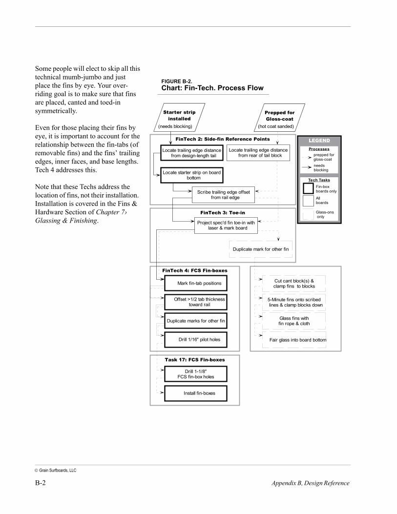
IN THIS CHAPTERThis supplement contains Techs related to the postitioning of fins..They relate the step-by-step details of what is a logical series of steps given the fin location figures provided in the Builder’s Manual. If that table is enough for you to go by, or you wish to locate fins by eye, Tech 1 through Tech 4 can be skipped. Figure B-2 shows how this section is organized where the two starting points refer to the instances where you would be referred to the Fin Techs.
TECH 1: FIN SETUP DISCUSSION
This section will discuss the location of fins, as well as criteria to use in decision-making, and methods for positioning fins and the blocking needed to support them when that is prescribed.
Things to consider when positioning fins.
Tech 1: Fin Setup Discussion . . . . . . . . . . . . . . . . . . . . . . . . B-1Chart: Fin-Tech. Process Flow. . . . . . . . . . . . . . . . . . . . . . . . . . B-2Tech 2: Side-fin Reference Points . . . . . . . . . . . . . . . . . . . . B-3Tech 3: Fin Toe-in . . . . . . . . . . . . . . . . . . . . . . . . . . . . . . . . . . B-8Tech 4: Siting FCS fin-boxes . . . . . . . . . . . . . . . . . . . . . . . . B-13
FIGURE B-1. Fin dimensioning nomenclature (FCS fin shown).
Appendix B› Supplement: Fin Positioning
B-2 Appendix B, Design Reference
Grain Surfboards, LLC
Some people will elect to skip all this technical mumb-jumbo and just place the fins by eye. Your over-riding goal is to make sure that fins are placed, canted and toed-in symmetrically.
Even for those placing their fins by eye, it is important to account for the relationship between the fin-tabs (of removable fins) and the fins’ trailing edges, inner faces, and base lengths. Tech 4 addresses this.
Note that these Techs address the location of fins, not their installation. Installation is covered in the Fins & Hardware Section of Chapter 7› Glassing & Finishing.
Starter stripinstalled
Prepped forGloss-coat
FinTech 2: Side-fin Reference Points
Locate starter strip on boardbottom
Scribe trailing edge offsetfrom rail edge
Locate trailing edge distancefrom design-length tail
Locate trailing edge distancefrom rear of tail block
FinTech 3: Toe-in
FinTech 4: FCS Fin-boxes
Project spec'd fin toe-in withlaser & mark board
Duplicate mark for other fin
(hot coat sanded)(needs blocking)
Mark fin-tab positions
Offset >1/2 tab thicknesstoward rail
Drill 1/16" pilot holes
FinTech 6: Glass-ons
Cut cant block(s) &clamp fins to blocks
5-Minute fins onto scribedlines & clamp blocks down
Glass fins withfin rope & clothDuplicate marks for other fin
Fair glass into board bottom
LEGEND
Processesprepped forgloss-coatneedsblocking
Tech Tasks
Glass-ons only
Allboards
Fin-boxboards only
Task 17: FCS Fin-boxes
Drill 1-1/8"FCS fin-box holes
Install fin-boxes
FIGURE B-2.Chart: Fin-Tech. Process Flow

B-3
Grain Surfboards, LLC
TECH 2: SIDE-FIN REFERENCE POINTS
Before setting fin-boxes, or positioning glass-on fins, we must locate the reference points from which to measure, then identify the point on the board where either the leading and trailing edge will land (in Figure B-3). There are two instances when we might be doing this:
• when installing blocking into a board with no top planks yet installed
• when preparing to glass on fins to a nearly complete board.
Following the location of these reference points fin toe-in and cant must be established, and the fin-boxes must be positioned with proper toe-in.
The following steps are the first required in setting side fins.
Goal: Determine the critical reference points for positioning side-fin blocking or glass-on fins near rails.
Application: FCS, Lokbox, or Future fins need to be installed near the rails in specified positions, and the board has a starter strip and few if any other railstrips installed.
FIGURE B-3. Initial reference point for trailing edge location - ‘x’ marks the spot..
Step Action Result
In these steps, we need to determine where the tail and rails will be because they are typical reference points for the dimensions that locate the fins themselves. This presents a problem because the Tech may be referenced when the board is only just started. The board may not be at full length yet if tailblocks are still be installed, and the bottom planks stick out beyond the rails.
B.2.1 If it is not done already, determine the total length of the board using a tape measure - measure from the length mark you made at the nose in Step 6.1.4 (page 29), extended straight back to the tail of the board. If the board is to get tail blocks, but they aren’t installed yet, it may be shorter than the design (final) length.
If it is shorter than design length, note the length of the bottom planks at the center line/keel. Subtract the current length of the bottom planks from the design length. This number - representing the missing tail blocks - will be used in subsequent steps (see Figure B-5). If longer than design length, cut off the bottom planks to design length, square to the center line/keel.
Establish a board length established, or a dimen-sion that represents how much shorter the board is than its final length.
FIGURE B-4. Measuring surfboard length
B-4 Appendix B, Design Reference
Grain Surfboards, LLC
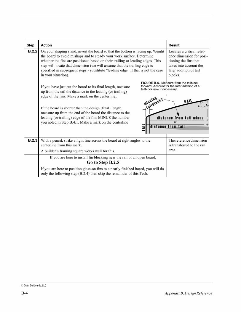
B.2.2 On your shaping stand, invert the board so that the bottom is facing up. Weight the board to avoid mishaps and to steady your work surface. Determine whether the fins are positioned based on their trailing or leading edges. This step will locate that dimension (we will assume that the trailing edge is specified in subsequent steps - substitute “leading edge” if that is not the case in your situation).
If you have just cut the board to its final length, measure up from the tail the distance to the leading (or trailing) edge of the fins. Make a mark on the centerline..
If the board is shorter than the design (final) length, measure up from the end of the board the distance to the leading (or trailing) edge of the fins MINUS the number you noted in Step B.4.1. Make a mark on the centerline
Locates a critical refer-ence dimension for posi-tioning the fins that takes into account the later addition of tail blocks.
B.2.3 With a pencil, strike a light line across the board at right angles to the centerline from this mark. A builder’s framing square works well for this.
The reference dimension is transferred to the rail area.
If you are here to install fin blocking near the rail of an open board, Go to Step B.2.5
If you are here to position glass-on fins to a nearly finished board, you will do only the following step (B.2.4) then skip the remainder of this Tech.
Step Action Result
FIGURE B-5. Measure from the tailblock forward. Account for the later addition of a tailblock now if necessary.
B-5
Grain Surfboards, LLC
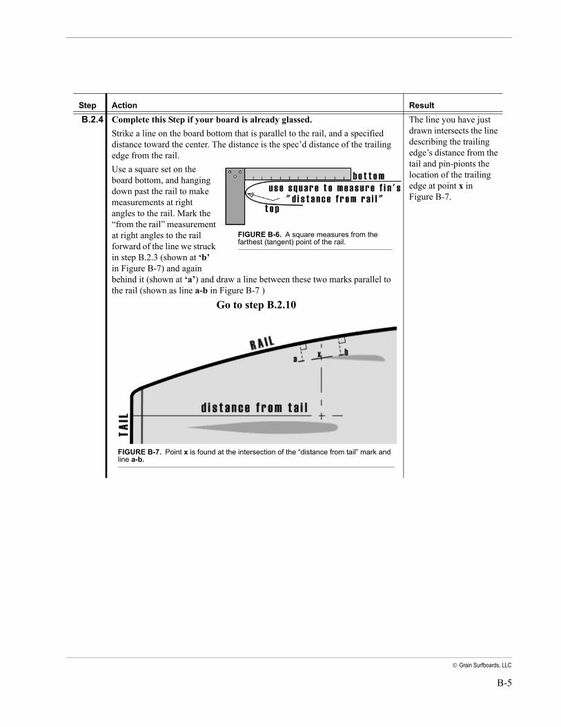
B.2.4 Complete this Step if your board is already glassed. Strike a line on the board bottom that is parallel to the rail, and a specified distance toward the center. The distance is the spec’d distance of the trailing edge from the rail.Use a square set on the board bottom, and hanging down past the rail to make measurements at right angles to the rail. Mark the “from the rail” measurement at right angles to the rail forward of the line we struck in step B.2.3 (shown at ‘b’ in Figure B-7) and again behind it (shown at ‘a’) and draw a line between these two marks parallel to the rail (shown as line a-b in Figure B-7 )
Go to step B.2.10
The line you have just drawn intersects the line describing the trailing edge’s distance from the tail and pin-pionts the location of the trailing edge at point x in Figure B-7.
Step Action Result
FIGURE B-6. A square measures from the farthest (tangent) point of the rail.
FIGURE B-7. Point x is found at the intersection of the “distance from tail” mark and line a-b.
B-6 Appendix B, Design Reference
Grain Surfboards, LLC
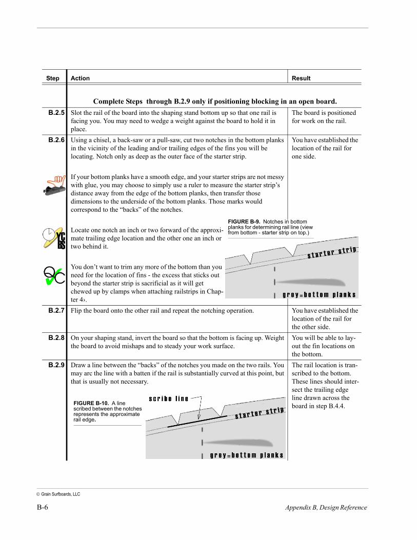
Complete Steps through B.2.9 only if positioning blocking in an open board.B.2.5 Slot the rail of the board into the shaping stand bottom up so that one rail is
facing you. You may need to wedge a weight against the board to hold it in place.
The board is positioned for work on the rail.
B.2.6 Using a chisel, a back-saw or a pull-saw, cut two notches in the bottom planks in the vicinity of the leading and/or trailing edges of the fins you will be locating. Notch only as deep as the outer face of the starter strip.
If your bottom planks have a smooth edge, and your starter strips are not messy with glue, you may choose to simply use a ruler to measure the starter strip’s distance away from the edge of the bottom planks, then transfer those dimensions to the underside of the bottom planks. Those marks would correspond to the “backs” of the notches.
Locate one notch an inch or two forward of the approxi-mate trailing edge location and the other one an inch or two behind it.
You don’t want to trim any more of the bottom than you need for the location of fins - the excess that sticks out beyond the starter strip is sacrificial as it will get chewed up by clamps when attaching railstrips in Chap-ter 4›.
You have established the location of the rail for one side.
B.2.7 Flip the board onto the other rail and repeat the notching operation. You have established the location of the rail for the other side.
B.2.8 On your shaping stand, invert the board so that the bottom is facing up. Weight the board to avoid mishaps and to steady your work surface.
You will be able to lay-out the fin locations on the bottom.
B.2.9 Draw a line between the “backs” of the notches you made on the two rails. You may arc the line with a batten if the rail is substantially curved at this point, but that is usually not necessary.
The rail location is tran-scribed to the bottom. These lines should inter-sect the trailing edge line drawn across the board in step B.4.4.
Step Action Result
FIGURE B-9. Notches in bottom planks for determining rail line (view from bottom - starter strip on top.)
FIGURE B-10. A line scribed between the notches represents the approximate rail edge.
B-7
Grain Surfboards, LLC
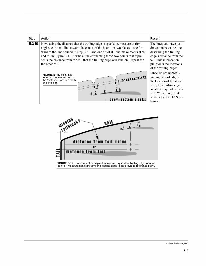
B.2.10 Now, using the distance that the trailing edge is spec’d to, measure at right angles to the rail line toward the center of the board in two places - one for-ward of the line scribed in step B.2.3 and one aft of it - and make marks at ‘b’ and ‘a’ in Figure B-11. Scribe a line connecting these two points that repre-sents the distance from the rail that the trailing edge will land on. Repeat for the other rail.
The lines you have just drawn intersect the line describing the trailing edge’s distance from the tail. This intersection pin-pionts the locations of the trailing edges.Since we are approxi-mating the rail edge at the location of the starter strip, this trailing edge location may not be per-fect. We will adjust it when we install FCS fin-boxes.
Step Action Result
FIGURE B-11. Point x is found at the intersection of the “distance from tail” mark and line a-b.
FIGURE B-12. Summary of principle dimensions required for trailing edge location (point x). Measurements are similar if leading edge is the provided reference point.
B-8 Appendix B, Design Reference
Grain Surfboards, LLC
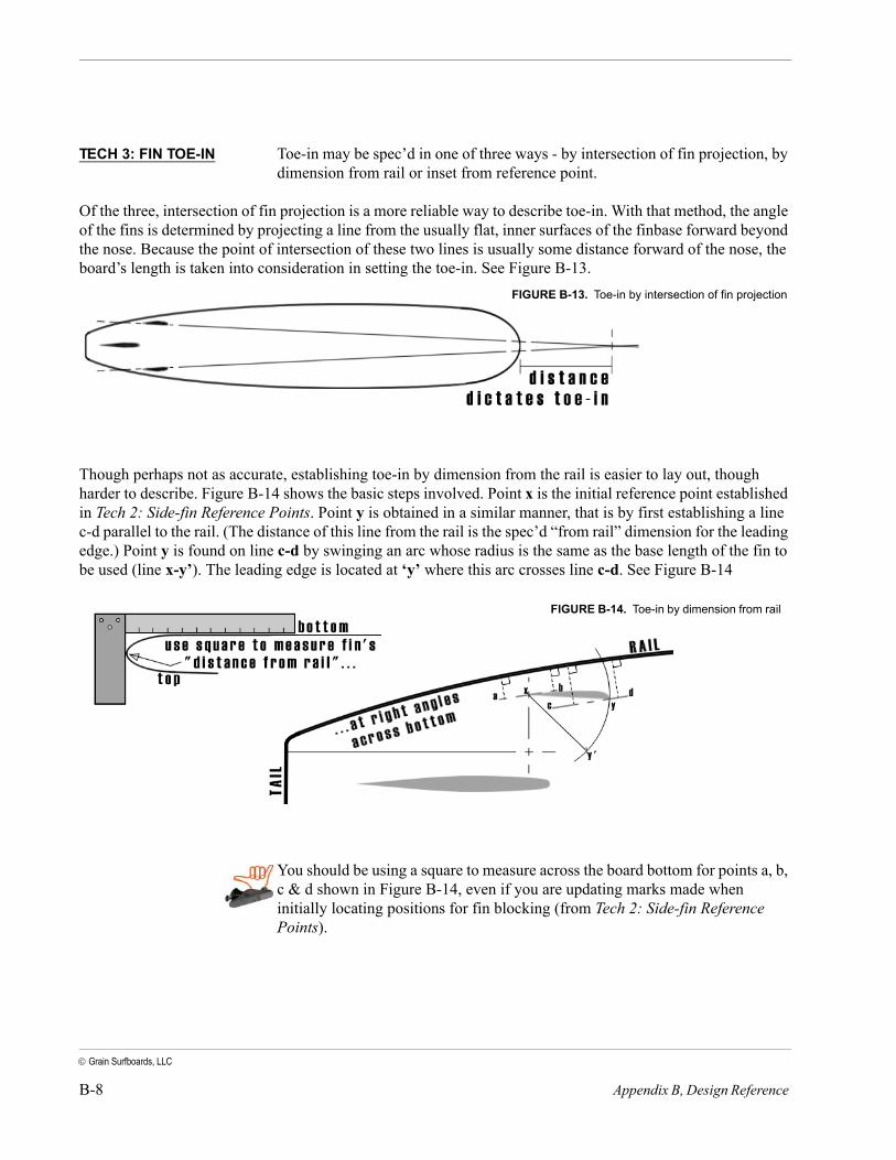
TECH 3: FIN TOE-IN Toe-in may be spec’d in one of three ways - by intersection of fin projection, by dimension from rail or inset from reference point.
Of the three, intersection of fin projection is a more reliable way to describe toe-in. With that method, the angle of the fins is determined by projecting a line from the usually flat, inner surfaces of the finbase forward beyond the nose. Because the point of intersection of these two lines is usually some distance forward of the nose, the board’s length is taken into consideration in setting the toe-in. See Figure B-13.
Though perhaps not as accurate, establishing toe-in by dimension from the rail is easier to lay out, though harder to describe. Figure B-14 shows the basic steps involved. Point x is the initial reference point established in Tech 2: Side-fin Reference Points. Point y is obtained in a similar manner, that is by first establishing a line c-d parallel to the rail. (The distance of this line from the rail is the spec’d “from rail” dimension for the leading edge.) Point y is found on line c-d by swinging an arc whose radius is the same as the base length of the fin to be used (line x-y’). The leading edge is located at ‘y’ where this arc crosses line c-d. See Figure B-14
You should be using a square to measure across the board bottom for points a, b, c & d shown in Figure B-14, even if you are updating marks made when initially locating positions for fin blocking (from Tech 2: Side-fin Reference Points).
FIGURE B-13. Toe-in by intersection of fin projection
FIGURE B-14. Toe-in by dimension from rail

B-9
Grain Surfboards, LLC
The third method simply utilizes a dimension from the trailing edge location inset toward the center of the board. The dimension, representing the amount of toe-in, is sometimes specified for the fin-set as a whole, and sometimes refers to a single fin. In other words, a measurement between the leading edges (distance ‘Z’) is smaller than a measurement between the trailing edges by the amount for the set. Each fin may be said to be toed-in half that amount. So, the fin set is said to be toed-in (line x-x’’ minus Z) and each fin, (line x-x’ minus Z/2).
Very small changes in the dimensions used for creating line a-b and line c-d will result in large changes to the distance from the nose that the projected lines of the side-fins will cross. It is a sound policy to validate toe-ins established by dimension (as shown in Figure B-14 and B-15) with the projection method shown in Figure B-13.
Obviously, toe-in should be perfectly equal on both sides of the board. Where appropriate care was exercised in laying out and installing the bottom planks, the center seam (if there is one) should be exactly down the center of the board’s length and can be used to duplicate the position of the second side-fin.
Goal: Establish or verify fin toe-in using projection.
Application: The first reference points for locating side-fins are marked on a board, and the fin’s angle to the centerline of the board needs to be established so a fin may be glassed on, or fin-boxes or blocking may be installed in the correct positions.
FIGURE B-15. (left) Toe-in by inset dimension.
Step Action Result
You will use a pencil to make marks on the board during this Tech. If you are working with a board that is already glassed at this point (i.e. you are installing FCS fin-boxes, or positioning glass-on fins) then you will find it easier if your hot-coat is already sanded so that pencil marks will be visible.Whether on glass or bare wood, pencil marks should only be dark enough to be visible as in all cases, marks will need to be sanded or washed off later
B.3.1 Place the board on your shaping stand with the bottom facing up. Weight it to steady your work surface and prevent mishaps.
The board is upside-down and steady.

B-10 Appendix B, Design Reference
Grain Surfboards, LLC
B.3.2 Position the stand and board so that the nose of the board is the same distance from a blank wall as the projection distance, and tape a couple of pieces of plain, white paper in line with the center of the board. You can also set up a step ladder with a piece of plain, white paper hanging from it at the correct dis-tance. The “projection distance” is the critical dimension that dictates the toe-in. You will find that it takes a large change of projection distance to make even a mea-surable change in the toe-in for each fin. Conversely, a small change in toe-in dimension makes a large change in projection distance. This is why projecting the fins’ toe-in is so much more reliable.
We create a surface for-ward of the board for for lasers -that represent the projected line of the fins - to shine onto.
B.3.3 Use a torpedo level or 24” spirit level near a frame of the board which is flat from rail-to-rail to make sure that the board is level.When using builder’s lasers in the following steps, make sure that the spirit levels in the laser are centered (meaning that the unit is level and its line will be vertical.)
All the lines projected are close to vertical.
B.3.4 Set a builder’s laser on the bottom of the board near the tail so that it projects a vertical line toward the nose exactly up the centerline of the bottom.This is where care in placing your bottom planks onto the keel really helps - if it was done right, you should be able to use a center seam as a center-line refer-ence. Before doing so, verify that the seam is in the center of the board.Note that when the plank layout was designed with a center plank, instead of a book-matched pair, the bottom won’t have a seam directly under the keel. In these cases, marks need to be scribed to identify the centerline.
You should see a verti-cal laser line projected against the wall or paper you
B.3.5 If you have only one laser, mark the paper where the line hit it. You will be moving the laser to use it a second time, so at this point, don’t jig-gle the board at all, or your results will be affected.If you don’t have any lasers at all (they can be bought for $15 - $35 at any building supply), then you can use string, spirit levels, a combination square and a friend instead. Be inventive: you are only trying to establish lines that are referenced from the board’s bottom (the centerline and fin baselines), extend them past the nose of the board, and ensure that they intersect at a certain point.
The intersection point for both fins is projected forward to the same ver-tical line.
B.3.6 Clamp a planking off-cut to the bottom of the board at right angles to the cen-terline as far back at the tail as is possible so that the plank sticks well out over the rail.
You have a platform that is sufficiently outboard for the builder’s laser.
Step Action Result
FIGURE B-16. Project against a surface
B-11
Grain Surfboards, LLC
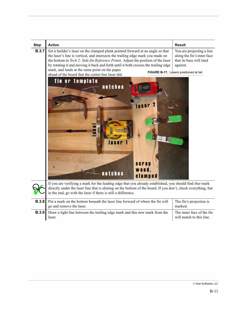
B.3.7 Set a builder’s laser on the clamped plank pointed forward at an angle so that the laser’s line is vertical, and intersects the trailing edge mark you made on the bottom in Tech 2: Side-fin Reference Points. Adjust the position of the laser by rotating it and moving it back and forth until it both crosses the trailing edge mark, and lands at the same point on the paper ahead of the board that the center-line laser did.
You are projecting a line along the fin’s inner face that its base will land against.
If you are verifying a mark for the leading edge that you already established, you should find that mark directly under the laser line that is shining on the bottom of the board. If you don’t, check everything, but in the end, go with the laser if there is still a difference.
B.3.8 Put a mark on the bottom beneath the laser line forward of where the fin will go and remove the laser.
The fin’s projection is marked.
B.3.9 Draw a light line between the trailing edge mark and this new mark from the laser.
The inner face of the fin will match to this line.
Step Action Result
FIGURE B-17. Lasers positioned at tail
B-12 Appendix B, Design Reference
Grain Surfboards, LLC
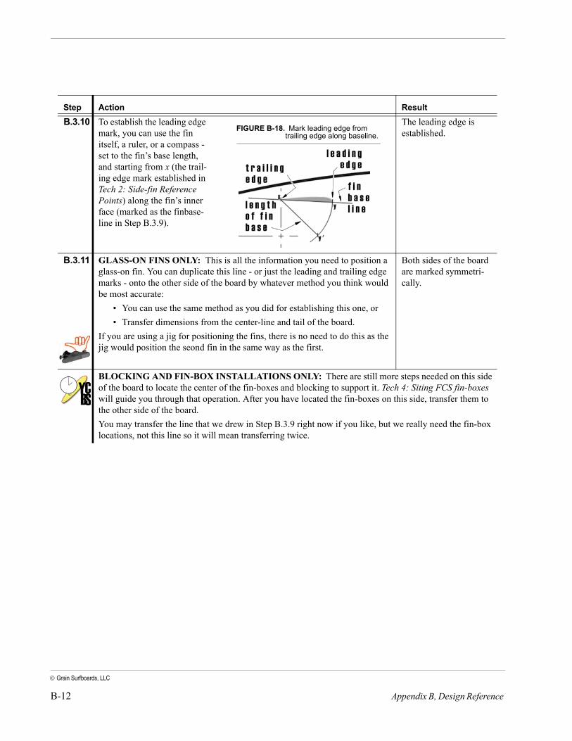
B.3.10 To establish the leading edge mark, you can use the fin itself, a ruler, or a compass - set to the fin’s base length, and starting from x (the trail-ing edge mark established in Tech 2: Side-fin Reference Points) along the fin’s inner face (marked as the finbase-line in Step B.3.9).
The leading edge is established.
B.3.11 GLASS-ON FINS ONLY: This is all the information you need to position a glass-on fin. You can duplicate this line - or just the leading and trailing edge marks - onto the other side of the board by whatever method you think would be most accurate:
• You can use the same method as you did for establishing this one, or • Transfer dimensions from the center-line and tail of the board.
If you are using a jig for positioning the fins, there is no need to do this as the jig would position the seond fin in the same way as the first.
Both sides of the board are marked symmetri-cally.
BLOCKING AND FIN-BOX INSTALLATIONS ONLY: There are still more steps needed on this side of the board to locate the center of the fin-boxes and blocking to support it. Tech 4: Siting FCS fin-boxes will guide you through that operation. After you have located the fin-boxes on this side, transfer them to the other side of the board.You may transfer the line that we drew in Step B.3.9 right now if you like, but we really need the fin-box locations, not this line so it will mean transferring twice.
Step Action Result
FIGURE B-18. Mark leading edge from trailing edge along baseline.
B-13
Grain Surfboards, LLC
TECH 4: SITING FCS FIN-BOXES
For this section, refer to Figure B-1.
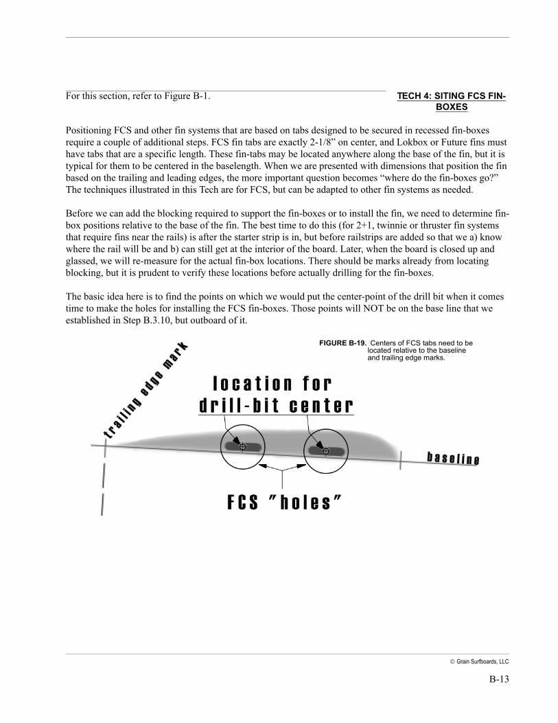
Positioning FCS and other fin systems that are based on tabs designed to be secured in recessed fin-boxes require a couple of additional steps. FCS fin tabs are exactly 2-1/8” on center, and Lokbox or Future fins must have tabs that are a specific length. These fin-tabs may be located anywhere along the base of the fin, but it is typical for them to be centered in the baselength. When we are presented with dimensions that position the fin based on the trailing and leading edges, the more important question becomes “where do the fin-boxes go?” The techniques illustrated in this Tech are for FCS, but can be adapted to other fin systems as needed.
Before we can add the blocking required to support the fin-boxes or to install the fin, we need to determine fin-box positions relative to the base of the fin. The best time to do this (for 2+1, twinnie or thruster fin systems that require fins near the rails) is after the starter strip is in, but before railstrips are added so that we a) know where the rail will be and b) can still get at the interior of the board. Later, when the board is closed up and glassed, we will re-measure for the actual fin-box locations. There should be marks already from locating blocking, but it is prudent to verify these locations before actually drilling for the fin-boxes.
The basic idea here is to find the points on which we would put the center-point of the drill bit when it comes time to make the holes for installing the FCS fin-boxes. Those points will NOT be on the base line that we established in Step B.3.10, but outboard of it.
FIGURE B-19. Centers of FCS tabs need to be located relative to the baseline and trailing edge marks.
B-14 Appendix B, Design Reference
Grain Surfboards, LLC
Goal: Locate the points that will be the centers of FCS fin-boxes for side-fins.
Application: A line has been marked on the board’s bottom representing where the inner face (baseline) of side-fins land on the board. Fin’s trailing edge location is also marked
Action Result
FCS makes different patterns and jigs for placing their fin-boxes. These save time and should be employed if they are available. If you don’t have these jigs, you can use the fins that you will be using with the board to similar effect, provided you don’t get any epoxy on them.
B.4.1 On the FCS fin placement jig (if you are using one), mark with small pieces of masking tape the base length dimension of the fin you will be using, or use the fin itself.
Your fin template is marked for making measurements.
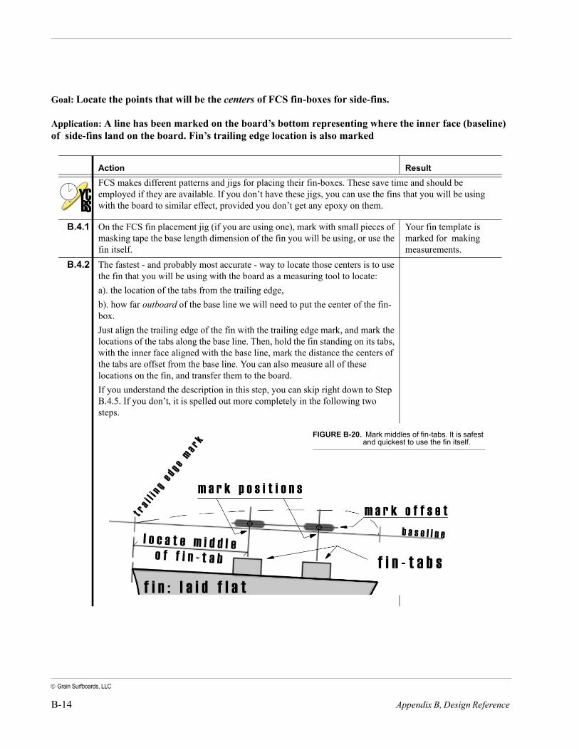
B.4.2 The fastest - and probably most accurate - way to locate those centers is to use the fin that you will be using with the board as a measuring tool to locate: a). the location of the tabs from the trailing edge, b). how far outboard of the base line we will need to put the center of the fin-box. Just align the trailing edge of the fin with the trailing edge mark, and mark the locations of the tabs along the base line. Then, hold the fin standing on its tabs, with the inner face aligned with the base line, mark the distance the centers of the tabs are offset from the base line. You can also measure all of these locations on the fin, and transfer them to the board. If you understand the description in this step, you can skip right down to Step B.4.5. If you don’t, it is spelled out more completely in the following two steps.
FIGURE B-20. Mark middles of fin-tabs. It is safest and quickest to use the fin itself.
B-15
Grain Surfboards, LLC
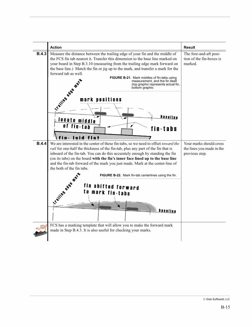
B.4.3 Measure the distance between the trailing edge of your fin and the middle of the FCS fin tab nearest it. Transfer this dimension to the base line marked on your board in Step B.3.10 (measuring from the trailing edge mark forward on the base line.) Match the fin or jig up to the mark, and transfer a mark for the forward tab as well.
The fore-and-aft posi-tion of the fin-boxes is marked.
B.4.4 We are interested in the center of these fin-tabs, so we need to offset toward the rail for one-half the thickness of the fin-tab, plus any part of the fin that is inboard of the fin-tab. You can do this accurately enough by standing the fin (on its tabs) on the board with the fin’s inner face lined up to the base line and the fin-tab forward of the mark you just made. Mark at the center-line of the both of the fin tabs.
Your marks should cross the lines you made in the previous step.
FCS has a marking template that will allow you to make the forward mark made in Step B.4.3. It is also useful for checking your marks.
Action Result
FIGURE B-21. Mark middles of fin-tabs using measurement, and the fin itself.(top graphic represents actual fin, bottom graphic
FIGURE B-22. Mark fin-tab centerlines using the fin.

B-16 Appendix B, Design Reference
Grain Surfboards, LLC
B.4.5 Use the fin or a marking template to confirm your marks. When you are confi-dent that you have them in the right place, you can duplicate them onto the opposite side of the board. If you set your bottom planks accurately, then you may be able to see almost perfect symmetry in the relative position of marks and plank seams. Don’t rely on this if you are not confident of your keel placement or planking.
Two pairs of marks are made that mirror each other from side to side - same distance from rails, centerline, plank seams, etc.
B.4.6 Look it all over very carefully. Check measurements, look for symmetry. Once you are confident of the marks, then you we will want to mark them indelibly. If you are preparing to install the FCS fin-boxes now, use an awl - just enough to make a deep dimple in the fiberglass. Don’t make this bigger than you need to, but you can pierce the glass if you want.
The fin-box positions are permanently marked.
B.4.7 If you are preparing to install blocking, you want to drill a pilot hole using a small drillbit (about 1/16”) at right angles to the bottom planks. Drill right through into the inside of the board.
Four holes will be visi-ble inside the board to help locate blocking accurately.
B.4.8 Clean up the board - erase all marks on fiberglass or wash it with denatured alcohol. Return all jigs and tools.You don’t need to worry too much about marks on boards that are not glassed yet - there will be plenty of sanding later that will take it out.
The board is ready for its next operation.
Action Result
FIGURE B-23. Marks should align with centers of fin-tab