appendix c process control narrative - … · the city of winnipeg specifications bid opportunity...
TRANSCRIPT

The City of Winnipeg Specifications Bid Opportunity No. 940-2011 Template Version: C220110218 - C Bldg
APPENDIX C
PROCESS CONTROL NARRATIVE

Perimeter Road Pumping Station Raw Sewage Pump P3 Replacement
Controls Narrative
FINAL November 2011

City of Winnipeg Perimeter Road Pumping Station Raw Sewage Pump P3 Replacement November, 2011 Controls Narrative 10-0107-23
i
TABLE OF CONTENTS PAGE
1.0 SYSTEM DESCRIPTION..................................................................................................1 2.0 REFERENCE DRAWINGS ...............................................................................................2 3.0 NORMAL OPERATION.....................................................................................................3
3.1 PUMP M100PP DISCHARGE PLUG VALVE FV-M100................................................4 3.2 PUMP M100PP .............................................................................................................5 3.3 PUMP M200PP DISCHARGE PLUG VALVE FV-M200................................................5 3.4 PUMP M200PP .............................................................................................................6 3.5 PUMP M300PP DISCHARGE PLUG VALVE FV-M300................................................6 3.6 PUMP M300PP .............................................................................................................6 3.7 PUMP M400PP .............................................................................................................7 3.8 PUMP M810PP .............................................................................................................7 3.9 STATION DISCHARGE VALVES FV-M601 AND FV-M611 .........................................7 3.10 MAIN SERVICE BREAKERS STATUS.........................................................................8
4.0 REDUCED CAPACITY OPERATION ...............................................................................9 5.0 MANUAL OPERATION ...................................................................................................11 6.0 AUTOMATIC LEVEL CONTROL ....................................................................................12 APPENDICES
LIST OF APPENDICES
Appendix A DCS I/O List Appendix B Block Diagrams P:\Projects\2010\10-0107-23\Doc.Control\Issued\SOURCE\Docs\940-2011 BidOpp_2011-11-07\Appendix C\RPT_PerimeterRoad PumpP3 ReplacementControls Narrative_FNL_2011-11-07.doc

City of Winnipeg Perimeter Road Pumping Station Raw Sewage Pump P3 Replacement November, 2011 Controls Narrative 10-0107-23
1
1.0 SYSTEM DESCRIPTION
The Perimeter Road pumping station is the only pumping station receiving wastewater flow from
a significant part of west Winnipeg. Interruption of service at this station can quickly affect
upstream sewer levels. This can result in overflows to the river or basement flooding.
The raw sewage is pumped from the wetwell at the Perimeter Road Station using four pumps.
Three of the pumps are driven by electrical motors and the fourth one uses an internal
combustion engine and natural gas as fuel. All four have the capability of controlling pump
speed.
The pumps characteristics are summarized as follows:
Pump Capacity
[ML/Day]
Description
M100PP 22 to 95 400 HP (298 kW) electric motor with Variable Frequency Drive.
M200PP 8 to 41 200 HP (150 kW) electric motor with variable speed by magnetic
coupling between motor and pump.
M300PP 10 to 55 250 HP (190 kW) electric motor with Variable Frequency Drive.
M400PP 22 to 67 425 HP (@ 1700 RPM) variable speed by control type governor.
Each pump discharges into a common header which then discharges into two parallel discharge
pipes each with a magnetic flowmeter that monitors the flow pumped to the WEWPCC.
On the discharge of each magnetic flow meter is an automatic air operated valve to isolate the
station from the downstream pipeline in the event the drywell begins to flood.
City of Winnipeg Perimeter Road Pumping Station Raw Sewage Pump P3 Replacement November, 2011 Controls Narrative 10-0107-23
2
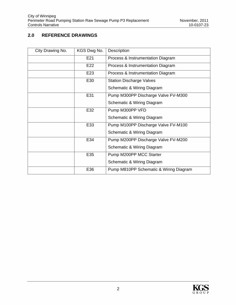
2.0 REFERENCE DRAWINGS
City Drawing No. KGS Dwg No. Description
E21 Process & Instrumentation Diagram
E22 Process & Instrumentation Diagram
E23 Process & Instrumentation Diagram
E30 Station Discharge Valves
Schematic & Wiring Diagram
E31 Pump M300PP Discharge Valve FV-M300
Schematic & Wiring Diagram
E32 Pump M300PP VFD
Schematic & Wiring Diagram
E33 Pump M100PP Discharge Valve FV-M100
Schematic & Wiring Diagram
E34 Pump M200PP Discharge Valve FV-M200
Schematic & Wiring Diagram
E35 Pump M200PP MCC Starter
Schematic & Wiring Diagram
E36 Pump M810PP Schematic & Wiring Diagram

City of Winnipeg Perimeter Road Pumping Station Raw Sewage Pump P3 Replacement November, 2011 Controls Narrative 10-0107-23
3
3.0 NORMAL OPERATION
Normal operation is defined when all pump local “computer-off-hand” selector switches are in
the computer position with the Bailey DCS controlling operation of the pumps. The pump
discharge valves (FV-M100, FV-M200 and FV-M300) have their local “open-online-close”
selector switches in the online mode while the station discharge valves (FV-M601 and FV-
M611) have their local “open-computer-close” selector switches in the computer mode.
Under normal operating conditions the control strategy for the raw sewage pumps is based on
the wet well level measurement. The span of this reading swings from 0% (227.4m) to 100%
(230.7m) but the control mode uses the range from 15% (227.9m) to 90% (230.37m). These
limits correspond to an estimated flow range of 0 to 115 ML/day.
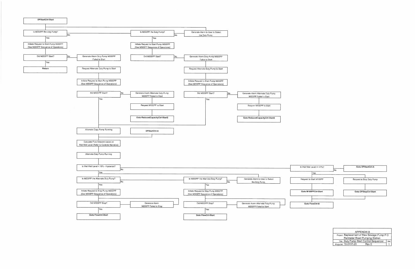
At 15% level and below, no raw sewage pumps are operating. On increasing level above 15%,
the duty pump M200PP or M300PP is started. Under normal operating conditions there is no
intention to run M200PP and M300PP at the same time. A HMI based selector switch is used to
select which of the two pumps is the duty pump. Between 15% and 41% level, the duty pump
modulates speed to maintain a set output flow. At 15% level the outflow is 0 ML/day and at
41% level the outflow is 40 ML/day.
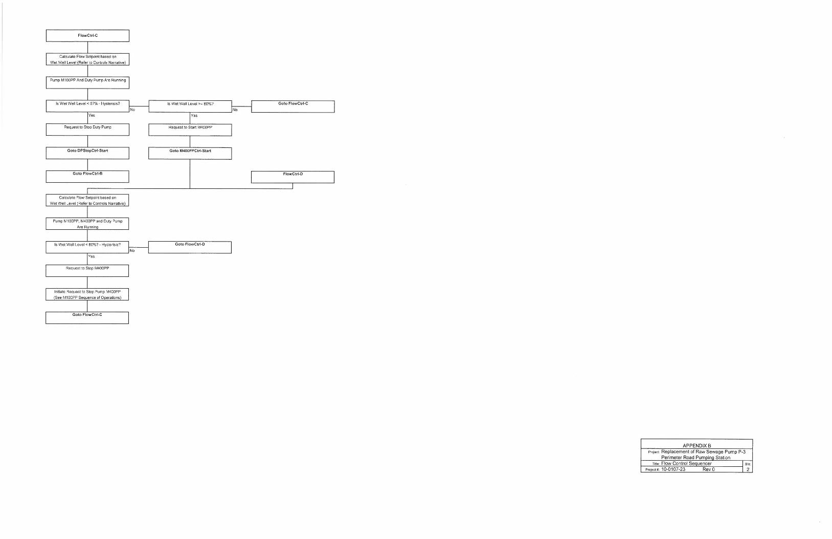
When the level increases above 41%, pump M100PP is started and the duty pump is stopped.
At that point, M100PP is pumping approximately 40 ML/day so that the switchover doesn’t
produce a bump in the pumped flow.
M100PP will operate between levels of 41% and 67%, changing its speed according to the
change in the level’s value. Within this range, M100PP will pump 40 to 80 ML/day.
When the level increases above 67%, the duty pump is started again at its maximum pumping
capacity. From 67% to 80% level, both M100PP and the duty pump will work together with
M100PP modulating speed to regulate the flow. Within the 67% to 80% level range the
corresponding flow will range from 80 to 100 ML/day.

City of Winnipeg Perimeter Road Pumping Station Raw Sewage Pump P3 Replacement November, 2011 Controls Narrative 10-0107-23
4
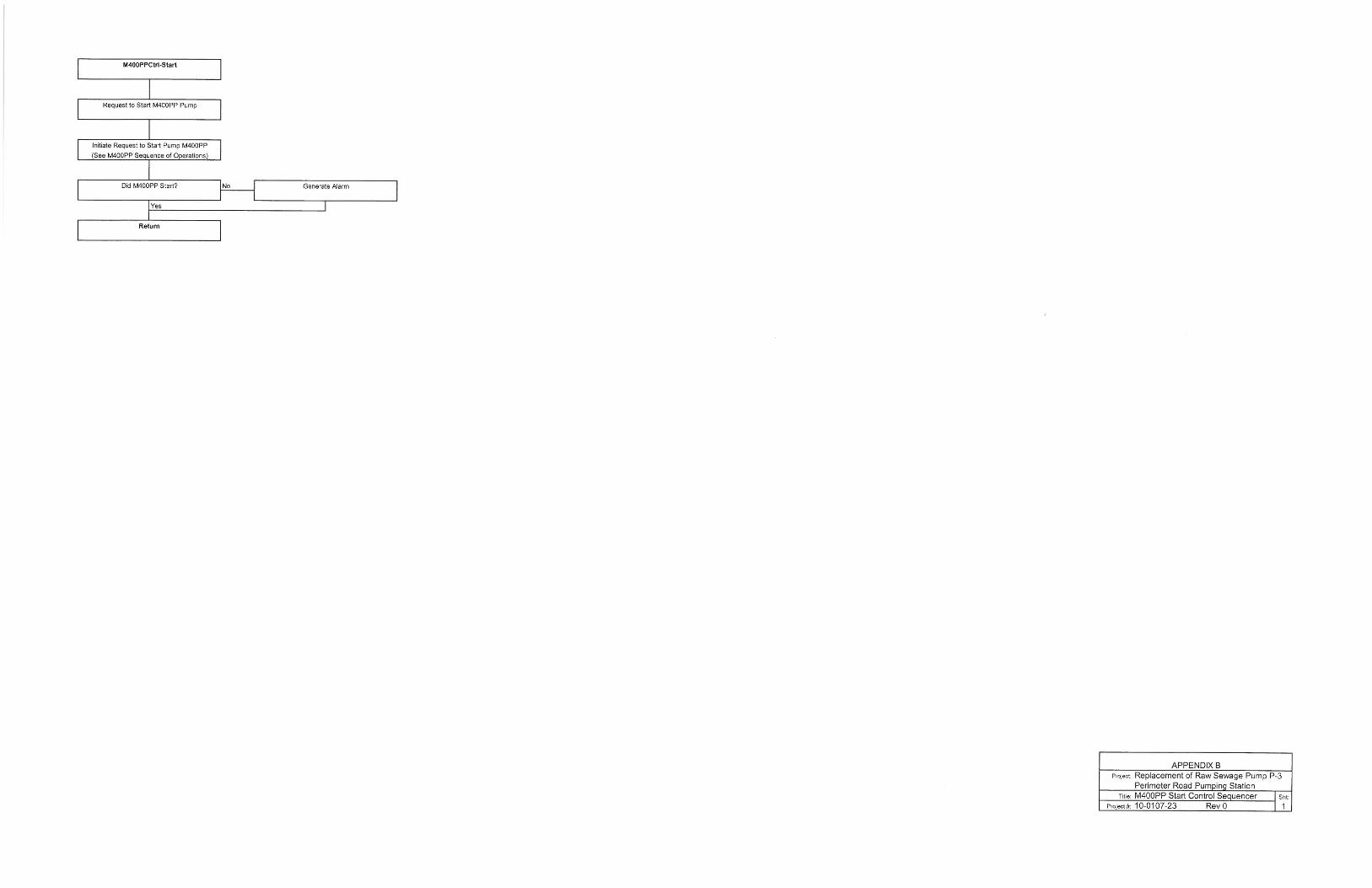
As the level increases over 80%, then M400PP is started. As the level increases from 80% to
90%, this pump will increase speed as required to bring flow output up to 115 ML/day.
On decreasing flow into the station wetwell and as the level starts to decrease, the pumps stop
in a last on first off fashion. A certain amount of hysteresis is provided to switch the pumps at
different levels to avoid rapid and unnecessary pump on-off cycling as minor flow variations
occur.
Figure 1 below shows the relationship between the pumped flow and the level in the wet well for
normal operation.
Pumped Flow vs. Wet Well Level
0
20
40
60
80
100
120
0 10 20 30 40 50 60 70 80 90 10
Level [%]
Flow
[ML/
day]
0
Figure 1
3.1 PUMP M100PP DISCHARGE PLUG VALVE FV-M100
During normal operation the local “close-online-open” selector switch is in the online position. In
online mode the valve receives an open command when pump M100PP is started and up to
minimum speed. In normal operation, with the pump selector switch in the computer position,
Duty Pump
+ M100PP
Duty Pump+
M100PP +
M400PP
M100PP
Duty Pump

City of Winnipeg Perimeter Road Pumping Station Raw Sewage Pump P3 Replacement November, 2011 Controls Narrative 10-0107-23
5
the open command to the valve is received from the DCS. Otherwise, the open command
signal comes from the pump M100PP starter when the pump is started in the hand position.
The valve has an open and close limit switch status as well as an “online” position status, all of
which are connected to the DCS.
3.2 PUMP M100PP
In normal operating mode, pump M100PP is activated at a wet well level of 41%. When running
it is becomes the modulating pump. This pump is used to achieve the desired pumping flow
based on the wet well level.
The pump starts with the discharge valve FV-M100 closed and comes up to a speed where it
begins pumping. At the pump minimum speed, FV-M100 will open completely. After the valve
is open and is proved by an open limit switch the pump can continue to speedup beyond its
minimum speed. Similarly on pump shutdown the pump slows down until the flow rate drops to
its minimum pumping speed at which time the discharge valve, FV-M100 closes. Once the
valve proves close via a close limit switch the pump will turn off.
3.3 PUMP M200PP DISCHARGE PLUG VALVE FV-M200
During normal operation the local “close-online-open” selector switch is in the online position. In
online mode the valve receives an open command when pump M200PP is started and up to
minimum speed. In normal operation, with the pump selector switch in the computer position,
the open command to the valve is received from the DCS. Otherwise, the open command
signal comes from the pump M200PP starter when the pump is started in the hand position.
The valve has an open and close limit switch status as well as an “online” position status, all of
which are connected to the DCS.

City of Winnipeg Perimeter Road Pumping Station Raw Sewage Pump P3 Replacement November, 2011 Controls Narrative 10-0107-23
6
3.4 PUMP M200PP
If selected as the duty pump M200PP operates between a wet well level of 15% and 41% where
is modulates the station effluent flow. At a wet well level of 67% or more, and while selected as
the duty pump M200PP will operate at full speed.
The startup and shutdown of pump M200PP is similar to operation of pump M100PP except that
its discharge valve FV-M200 is operated with pump M200PP.
In the event that pump M300PP is the duty pump and it experiences a failure, then pump
M200PP will operate as the duty pump.
3.5 PUMP M300PP DISCHARGE PLUG VALVE FV-M300
During normal operation the local “close-online-open” selector switch is in the online position. In
online mode the valve receives an open command when pump M200PP is started and up to
minimum speed. In normal operation, with the pump selector switch in the computer position,
the open command to the valve is received from the DCS. Otherwise, the open command
signal comes from the pump M200PP starter when the pump is started in the hand position.
The valve has an open and close limit switch status as well as an “online” position status, all of
which are connected to the DCS.
3.6 PUMP M300PP
If selected as the duty pump, M300PP operates between a wet well level of 15% and 41%
where is modulates the station effluent flow. At a wet well level of 67% or more, and while
selected as the duty pump, M300PP will operate at full speed.
The startup and shutdown of pump M300PP is similar to operation of pump M100PP except that
its discharge valve FV-M300 is operated with pump M300PP.

City of Winnipeg Perimeter Road Pumping Station Raw Sewage Pump P3 Replacement November, 2011 Controls Narrative 10-0107-23
7
In the event that pump M200PP is the duty pump and it experiences a failure, then pump
M300PP will operate as the duty pump.
3.7 PUMP M400PP
Pump M400PP operates when the wet well level reaches 80% level.
3.8 PUMP M810PP
In normal operation flushing water pump M810PP auto-manual switch is in the automatic
position. In automatic mode the pump is controlled via a series of pressure switches. The
pump is started by low pressure switch M811-PSL and stopped by high pressure switch M811-
PSH.
Two additional pressure switches M811-PAL and M811-PAH along with the pump run status
(starter auxiliary contact) report back to the DCS as status points.
3.9 STATION DISCHARGE VALVES FV-M601 AND FV-M611
In normal operation the station discharge valves FV-M601 and FV-M611 will have their local
“close-computer-open” selector switch in the computer mode. In computer mode the DCS has
control of the valves so that one of the station discharge valves is to be opened while any of the
4 raw sewage pumps M100PP, M200PP, M300PP or M400PP are operational.
Each valve has an open and close limit switch that are connected to the DCS complete with a
status light on the local control station. In Addition when the local switch is in the computer
position it has its position status connected back to the DCS.
A dry well high level switch LSH-M620 is interlocked to the two valves. This switch will close the
valves and provide a signal to prevent them from opening when the switch is in an alarm
condition. The high level switch has a local alarm light that reports back to the DCS as an alarm
condition. When both valves are closed this alarm condition will stop all four pumps from
running.
City of Winnipeg Perimeter Road Pumping Station Raw Sewage Pump P3 Replacement November, 2011 Controls Narrative 10-0107-23
8
3.10 MAIN SERVICE BREAKERS STATUS
The perimeter road pumping station has two electrical service feeds, one from the Rannock
Substation (Service A) and the other from Headingly Substation (Service B). The Rannock
Service is a 750 kW service while the Headingly service is a 450 kW service. Normally the
station is operating on the Rannock service and therefore can operate all pumps. If the
Headingly service is in use there are scenarios where only certain equipment may operate.
Under this condition Water and Waste will operate the station manually to ensure that the
service is not overloaded.
The station is equipped with two monitoring breaker contact within the main switchgear. One for
the Rannock service breaker contact ‘M715A-YS’ and another for the Headingly service breaker
contact ‘M715B-YS’. Each contact will provide the DCS with notification of with Hydro service is
supplying the station.

City of Winnipeg Perimeter Road Pumping Station Raw Sewage Pump P3 Replacement November, 2011 Controls Narrative 10-0107-23
9
4.0 REDUCED CAPACITY OPERATION When one or more pumps are not available, a different control sequence is applied. In the
event that the duty pump fails (M200PP or M300PP) then the alternate duty pump will start in its
place and continue to run the sequence of operations as stated under the normal operation.
In the event that pump M100PP fails, the alternate duty pump will start in conjunction with the
original duty pump. Normally both M200PP and M300PP do not operate together except in the
situation where M100PP is taken offline or fails to operate. In this situation when both the duty
pump and alternate duty pump are running the wet well is above 41% level. Under this
condition the duty pump will run at full speed while the alternate duty pump will modulate. At
67% level pump M400PP will start and pump up to the capacity 115 ML/day. This control
sequence is summarized in Figure 2 below.
Pumped Flow vs. Wet Well Level
0
20
40
60
80
100
120
0 10 20 30 40 50 60 70 80 90 10
Level [%]
Flow
[ML/
day]
0
Duty Pump
Duty Pump+
Alternate Duty Pump
Duty Pump+
Alternate Duty Pump+
M400PP
Figure 2
In the event that pump P400PP fails the pumps will operate according to Figure 3. In this
situation the sequence is normal until the flows increase over 100 ML/day at which point the

City of Winnipeg Perimeter Road Pumping Station Raw Sewage Pump P3 Replacement November, 2011 Controls Narrative 10-0107-23
10
alternate duty pump will start and run up to full speed with the M100PP acting as the modulating
pump.
Pumped Flow vs. Wet Well Level
0
20
40
60
80
100
120
0 10 20 30 40 50 60 70 80 90 10
Level [%]
Flow
[ML/
day]
0
Duty Pump+
M100PP+
Alternate DutyPump
Duty Pump+
M100PP
M100PP
Duty Pump
Figure 3

City of Winnipeg Perimeter Road Pumping Station Raw Sewage Pump P3 Replacement November, 2011 Controls Narrative 10-0107-23
11
5.0 MANUAL OPERATION
Pump M100PP may be operated manually via local start/stop pushbuttons. In manual mode of
operation the VFD speed is set manually via the VFD HMI display.
Pump M200PP may be operated manually via local start/stop pushbuttons. In manual mode the
speed of the magnetic slip drive is set via a dial local to the motor.
Pump M300PP may be operated manually via local start/stop pushbuttons. The speed controls
shall be via the local VFD display at the drive.
The pump valves FV-M100, FV-M200 and FV-M300 may be manually opened or closed by
using their local control switch, but these switch positions are for valve maintenance only and
the valve should be left in online mode for pump operation.
Pump M8100PP in hand mode runs only while high pressure switch M811-PSH is not made.
Station discharge valves FV-M601 and FV-M611 may be manually opened or closed by using
their local control switches. Operating the valves in manual does not affect the operation of the
raw sewage pumps in way.

City of Winnipeg Perimeter Road Pumping Station Raw Sewage Pump P3 Replacement November, 2011 Controls Narrative 10-0107-23
12
6.0 AUTOMATIC LEVEL CONTROL
The automatic level control is a complementary feature that allows for maintaining the wet well
level around a setpoint level.
The basic operation is similar to flow control in that pumps will switch on and off at similar pump
flow setpoints. The main difference is that the pump will speed up / slow down to maintain a
constant level in the wet well and stage pumps on and off only when the flows require it.

City of Winnipeg Perimeter Road Pumping Station Raw Sewage Pump P3 Replacement November, 2011 Controls Narrative 10-0107-23
APPENDICES

City of Winnipeg Perimeter Road Pumping Station Raw Sewage Pump P3 Replacement November, 2011 Controls Narrative 10-0107-23
APPENDIX A
DCS I/O LIST

I/O TypeTag Description DI DO AI AO Drawing New Point Existing Point Wiring TerminalsM601-FY Station Discharge Valve No.1 Open Command 1 E30 Y M601-1&2M601-HS Station Discharge Valve No.1 Switch in Computer Control Status 1 E30 Y M601-3&4M601-ZSD Station Discharge Valve No.1 Open Limit Switch 1 E30 Y M601-5&6M601-ZSB Station Discharge Valve No.1 Open Close Limit Switch 1 E30 Y M601-7&8M651-FY Station Discharge Valve No.2 Open Command 1 E30 Y M651-1&2M651-HS Station Discharge Valve No.2 Switch in Computer Control Status 1 E30 Y M651-3&4M651-ZSD Station Discharge Valve No.2 Open Limit Switch 1 E30 Y M651-5&6M651-ZSB Station Discharge Valve No.2 Open Close Limit Switch 1 E30 Y M651-7&8M715-LSH Dry Well High Level Alarm 1 E30 Y M715-24&25M715-HS Dry Well Float By Passed Alarm 1 E30 Y M715-1&2M300-FY Pump M300 Discharge Valve Open Command 1 E31 Y M300-40&41M300-HS Pump M300 Discharge Valve Switch in Online Mode 1 E31 Y M300-42&43M300-ZSD Pump M300 Discharge Valve Open Limit Switch 1 E31 Y M300-44&45M300-ZSB Pump M300 Discharge Valve Close Limit Switch 1 E31 Y M300-46&47M300-MN Pump M300 Start Command 1 E32 Y M300-1&3AM300-HS-A Pump M300 Switch in Hand Mode 1 E32 Y M300-18&19M300-HS-B Pump M300 Switch in Computer Mode 1 E32 Y M300-20&21M300-MM Pump M300 VFD Run Status 1 E32 Y M300-13&14M300-?? Pump M300 VFD Start Permissive 1 E32 Y M300-15&16M300-QA-A Pump M300 VFD Fault 1 E32 Y M300-22&23M300-QA-B Pump M300 Protection Relay Alarm 1 E32 Y M300-30&31M300-SC Pump M300 Speed Command 1 E32 Y M300-60&61M100-FY Pump M100 Discharge Valve Open Command 1 E33 Y M100-40&41M100-HS Pump M100 Discharge Valve Switch in Online Mode 1 E33 Y M100-42&43M100-ZSD Pump M100 Discharge Valve Open Limit Switch 1 E33 Y M100-44&45M100-ZSB Pump M100 Discharge Valve Close Limit Switch 1 E33 Y M100-46&47M200-FY Pump M200 Discharge Valve Open Command 1 E34 Y M200-40&41M200-HS Pump M200 Discharge Valve Switch in Online Mode 1 E34 Y M200-42&43M200-ZSD Pump M200 Discharge Valve Open Limit Switch 1 E34 Y M200-44&45M200-ZSB Pump M200 Discharge Valve Close Limit Switch 1 E34 Y M200-46&47M200-MN Pump M200 Start/Stop 1 E35 YM200-QA Pump M200 Fault 1 E35 YM811-PAL Pump M810 Low Pressure Switch 1 E36 YM811-PAH Pump M810 High Pressure Switch 1 E36 YM810-MM Pump M810 Run Status 1 E36 YM650-FIT Station Discharge No.2 Flowmeter 1 E24 Y M650-71(+),72(-),73(sh)M705A-YS Main Breaker 1 - Y M705-24&25M715-YS Main Breaker 1 - Y M715-24&25
P:\Projects\2010\10-0107-23\Doc.Control\Issued\SOURCE\Docs\940-2011 BidOpp_2011-11-07\Appendix C\PRPS_upgrade_IO_list Rev0.xls
APPENDIX AREPLACEMENT OF RAW SEWAGE PUMP P-3
PERIMETER ROAD PUMPING STATIONCONTROL SYSTEM ASSET LIST
REV 0
City of Winnipeg Perimeter Road Pumping Station Raw Sewage Pump P3 Replacement November, 2011 Controls Narrative 10-0107-23
APPENDIX B
BLOCK DIAGRAMS