appendix g: conceptual stormwater management...
TRANSCRIPT

CONCEPTUAL STORMWATER MANAGEMENT PLAN FOR THE
SUMMIT AT SNOQUALMIE
Submitted to:
SE Group, Inc. 3245 146th Pl. SE
Bellevue, Washington 98007
Submitted by:
Golder Associates Inc. 18300 NE Union Hill Road, Suite 200
Redmond, Washington 98052
_________________________ ____________________________ Andreas Q. Kammereck, P.E Charles W. Lockhart, P.E. Senior Engineer Senior Consultant __________________________ Colby L. Caywood, P.E. Project Engineer
July7, 2005 023-1209.000

Appendix G: Conceptual Stormwater Management Plan
The Summit-at-Snoqualmie Master Development Plan Proposal
Final Environmental Impact Statement G-i
TABLE OF CONTENTS
1.0 INTRODUCTION .............................................................................................................. 1
2.0 DESIGN OBJECTIVES AND CRITERIA ....................................................................... 2
3.0 PROPOSED STORMWATER MANAGEMENT PLAN ................................................ 4 3.1 Existing Condition ........................................................................................................ 4 3.2 Proposed Stormwater Facility Objectives ..................................................................... 4 3.3 Conceptual Treatment Train Alternatives ..................................................................... 5
3.3.1 B1 - Basic Treatment Train ............................................................................. 5 3.3.2 B2 - Basic Treatment Train with Oil and Grease Treatment ........................... 5 3.3.3 B3 - Bioswale at Discharge ............................................................................. 6 3.3.4 E1 - Enhanced Water Quality and Quantity Treatment Train ......................... 6
3.4 Parking Lot Grading Alternatives ................................................................................. 7 3.5 Proposed Conceptual Stormwater Facility Designs/Recommendations ....................... 7
3.5.1 Silver Fir Lot .................................................................................................... 7 3.5.2 Summit West Lot 2 .......................................................................................... 7 3.5.3 Summit West Lot 1 .......................................................................................... 8 3.5.4 Alpental Lot 3 .................................................................................................. 8 3.5.5 Alpental Lot 4 .................................................................................................. 8 3.5.6 Alpental Lot 5 .................................................................................................. 9 3.5.7 Alpental Lot 6 .................................................................................................. 9 3.5.8 Alpental Lot 7 .................................................................................................. 9 3.5.9 Alpental Road ................................................................................................ 10
4.0 SNOW MANAGEMENT ................................................................................................ 11 4.1 Proposed Strategies ..................................................................................................... 11
4.1.1 Creek Shelf Removal at Parking Lot A6 ....................................................... 11 4.1.2 Access Ramp Removal between A6 and A5 ................................................. 11 4.1.3 A6/A5 Pond and Switch ................................................................................ 12
5.0 CLOSURE ........................................................................................................................ 13
6.0 REFERENCES ................................................................................................................. 14
Appendix G: Conceptual Stormwater Management Plan
The Summit-at-Snoqualmie Master Development Plan Proposal
Final Environmental Impact Statement G-ii
LIST OF FIGURES
Figure 1 Project Area Site Map Figure 2 Silver Fir Parking Lot, Conceptual SMP Facility Layout Figure 3 SW1 and SW2 Parking Lots, Conceptual SMP Facility Layout Figure 4 Alpental Parking Lots, Conceptual SMP Facility Layout
LIST OF DRAWINGS
Drawing 1000 Conceptual Stormwater Management Treatment Train Alternatives Drawing 1010 Conceptual Parking Lot Grading Alternatives Drawing 1020 Conceptual Cross-Section of Lot A6 Shelf Removal Drawing 1030 Conceptual Layout for Pond and Switch Structure
LIST OF TABLES
Table 2-1 Proposed Quantitative SMP Performance Goals
LIST OF APPENDICES
Appendix A Conceptual Design Calculations Appendix B Typical Sections/Schematics for Stormwater Structures Appendix C Preliminary Unit Costs for Stormwater Structures
Appendix G: Conceptual Stormwater Management Plan
The Summit-at-Snoqualmie Master Development Plan Proposal
Final Environmental Impact Statement G-1
1.0 INTRODUCTION
This draft report presents our recommendations for the Conceptual Stormwater Management Plan (SMP) for various parking areas located within the Special Use Permit (SUP) boundary for the Summit at Snoqualmie (Summit) and the Alpental Ski areas. Those portions of the project area included in this report are outlined below. Section 3.2 provides a summary of the proposed improvements at each lot.
• Silver Fir (SF) Lot 1 at Summit East located just below the Silver Fir chair;
• Summit West Lot 2 (SW2) located between the maintenance building and the rental lodge;
• Summit West Lot 1 (SW1) located north of the rental lodge;
• Lot 3 at Alpental (A3) located on the east side of the South Fork Snoqualmie;
• Lot 4 at Alpental (A4) located on the west side of South Fork Snoqualmie;
• Lot 5 at Alpental (A5) located on the west side of South Fork Snoqualmie;
• Lot 6 at Alpental (A6) located on the west side of South Fork Snoqualmie; and,
• Lot 7 at Alpental (A7) located on the west side of South Fork Snoqualmie.
Refer to Figure 1 for a site map showing the lot locations. The following sections of this report define the objectives of the SMP, summarize the existing conditions, summarize the regulatory criteria used for recommendations in this conceptual report, and presents concepts for proposed stormwater facilities at each parking lot. In selected areas, additional alternative snow management recommendations are also provided.

Appendix G: Conceptual Stormwater Management Plan
The Summit-at-Snoqualmie Master Development Plan Proposal
Final Environmental Impact Statement G-2
2.0 DESIGN OBJECTIVES AND CRITERIA
The project area for this report addresses the public lands within the Master Development Plan (MDP) for the Summit. These public lands are under the jurisdiction of the United States Forest Service (USFS) within the Department of Agriculture (USDA), and are designated as National Forest System Lands (NFSL). Conceptual design alternatives for the SMP are therefore governed by Standards and Guidelines (S&G’s) provided in the Mount Baker-Snoqualmie National Forest Land and Resource Managfement Plan (USDA, 1990a) and the Wenatchee National Forest Land and Resource Management Plan (USDA, 1990b), as amended. These S&Gs include those provided in the Record of Decision for the Northwest Forest Plan (USDA, USDI, 1994) and as clarified in a 2004 Record of Decision (USDA, USDI, 2004). Under the 2004 clarifications, consistency with the ACS is to be determined through evaluation of project consistency with the Riparian Reserve S&G’s presented in the Northwest Forest Plan Record of Decision (USDA, USDI, 2004). This SMP has been designed to support consistency with S&G’s related to Riparian Reserves, as described in the EIS (refer to Section 1.2 – Tiering, Management Direction, U.S. Forest Service Policy).
In addition to addressing the Riparian Reserve S&Gs, the 2004 clarification indicates that a project record must evaluate the existing conditions of resources, display the effects of the project on the existing conditions, and then display efforts taken to avoid, minimize, mitigate, or otherwise reduce impacts on the aquatic environment. Inclusion of this SMP into the MDP is intended to serve as one method of reducing impacts of the MDP on the aquatic environment, as well as a potential means of maintaining or improving watershed conditions in the vicinity of parking areas on NFSL at The Summit (e.g., sediment delivery to streams, increased flows from impervious surfaces, snow management).
In general, this report has used the guidelines provided in the King County Surface Water Design Manual (KCSWDM, 1998) to further refine the criteria governing the development of this conceptual SMP. Table 2-1 below summarizes the key design criteria.
TABLE 2-1
Proposed Quantitative SMP Performance Goals Event Water Quality Sediment Regime In-stream Flows
6-month, 24-hour Maintain or reduce effluent concentrations of TSS1 and oil and grease
Maintain or increase the sediment trap efficiency
N/A
2-year, 24-hour N/A Same as for the 6-month, 24-hour event
Reduce the existing condition peak discharge by at least 50%
10-year, 24-hour N/A Same as for the 6-month, 24-hour event
Maintain or reduce the existing condition peak discharge
100-year, 24-hour N/A Same as for the 6-month, 24-hour event
Maintain or reduce the existing condition peak discharge
Notes: 1 Total Suspended Solids.

Appendix G: Conceptual Stormwater Management Plan
The Summit-at-Snoqualmie Master Development Plan Proposal
Final Environmental Impact Statement G-3
Design criteria outlined in the King County Surface Water Design Manual includes Flow Control, Conveyance Requirements and Water Quality Control. The Flow Control standard used in design meets the criteria outlined in Level 3 Flow Control which is defined as a duration and peak matching performance standard. Conveyance requirements include the design of new channels to convey the 100-year peak flow to prevent flooding and erosion problems.

Appendix G: Conceptual Stormwater Management Plan
The Summit-at-Snoqualmie Master Development Plan Proposal
Final Environmental Impact Statement G-4
3.0 PROPOSED STORMWATER MANAGEMENT PLAN
The following discussion outlines the existing condition of the project areas and summarizes proposed stormwater recommendations for targeted areas.
3.1 Existing Condition
There are no existing stormwater facilities in-place for the parking lot areas addressed under this report at the Summit or Alpental. In general, the existing parking areas consist of a compacted gravel surface graded in some cases to drain to the perimeter of the lot boundaries. No sediment or oil and grease treatment facilities are currently in place. Improvements through implementation of new stormwater facilities would therefore focus on addressing the fine grained sediment transported by run-off from the existing gravel surfaces and treating for oil and grease.
The following discussion provides an overview of the stormwater plan objectives, outlines treatment train alternatives, and provides recommendations to each parking area.
3.2 Proposed Stormwater Facility Objectives
The focus of the development of a stormwater plan for the Summit and Alpental parking lot areas is to provide comprehensive collection and routing of surface drainage water, improve water quality by addressing fine grained sediments, and treat for potential hydrocarbon contaminants.
Mitigating for fine grained sediments washing off the existing compacted gravel parking lots would be accomplished by paving all parking lot areas. It is therefore assumed that paving of the lot areas would significantly reduce the contribution of fine grained sediments. Paved parking areas would be graded generally towards the center of the lot, and/or away from the perimeter snow storage areas. Where parking lot areas are proposed to be increased in size, the increase in runoff would be treated (i.e. water quantity treatment) to maintain pre-developed conditions, per the criteria provided in Section 2.0, Table 2-1. Where no increase in parking area is proposed, runoff would be collected and routed to designated discharge locations.
Magnesium Chloride (MgCl) would be used as a deicer on all paved lot areas and at the Alpental road connecting the parking lots. Use of MgCl would eliminate the need for sanding. The combined treatment of paving and use of MgCl is assumed to significantly reduce potential sources of fine grained sediments originating from the project area. As an added precaution to mitigate for potential fine grained sediments, and in the event that localized sanding is necessary or other fine grained sediments are transported to the project area by vehicles traveling to the ski area(s), sediment traps would installed at all paved lot areas.
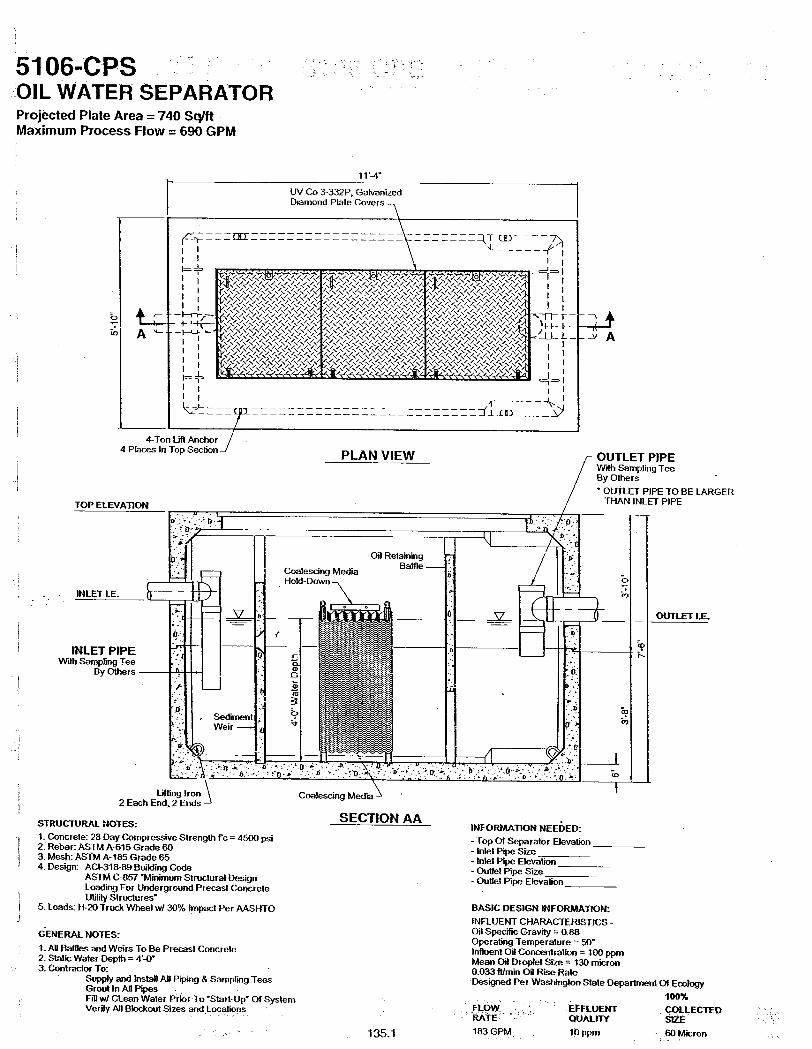
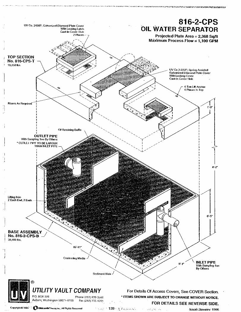
Oil and grease contaminants would be addressed through the installation of oil water separators (OWS) at each parking lot sub-basin discharge location. These would be sized to treat anticipated runoff corresponding to the design criteria outlined in Section 2.0. Schematics of an OWS are provided as examples in Appendix B for various flow ratings.
In general, we assumed that runoff quantities from compacted gravel surfaces during frozen winter conditions would be very similar to the runoff from paved surfaces (refer to Section 4.2 Geology and Soils of The Summit at Snoqualmie MDP DEIS). Treatment for increases in water quantity would be provided where parking lots are proposed to increase in size. Where water quantity treatment is required, underground vaults are proposed which would be located within the perimeter of the parking area. Section 3.3 below provides a more detailed discussion of the proposed alternatives for water quality and

Appendix G: Conceptual Stormwater Management Plan
The Summit-at-Snoqualmie Master Development Plan Proposal
Final Environmental Impact Statement G-5
quantity treatment. The final treatment process will be determined in the Record of Decision (ROD) for The Summit at Snoqualmie MDP. Currently, only Lot SW1 is proposed to increase in size.
The feasibility of the conceptual stormwater facilities proposed in this report is based on preliminary design assessments specific to the site. No site topographic survey was available for the feasibility assessment. We assume that a detailed survey would be completed to support the final design. The conceptual design recommendations are supported by calculations presented in Appendix A. Typical diagrams/schematics for individual stormwater facility components are provided in Appendix B. Preliminary planning level unit costs are provided in Appendix C. Final design and specification of stormwater facilities should be completed at the time of final SMP implementation using the detailed site specific survey information and the most current inventory of existing conditions.
3.3 Conceptual Treatment Train Alternatives
The following discussion outlines treatment train alternatives for achieving the water quality criteria provided in Section 2.0 and Table 2-1. A treatment train is defined as a sequence of stormwater quality and/or quantity treatment facilities. Conceptual parking lot grading alternatives are discussed in Section 3.4 below. Recommended treatment trains for each parking lot area are discussed in Section 3.5 below. In general, armored erosion control pads would be installed at all discharge locations. In all cases, the final location of erosion control pads, manholes, OWSs, vaults, piping or any other drainage facility would be coordinated with The Summit at Snoqualmie personnel to make sure that locations consider snow management operations and overall ski area management issues.
3.3.1 B1 - Basic Treatment Train
The B1 basic treatment train focuses primarily on helping attain the water quality standards for sediment. The basic treatment train consists of (in series) paved parking lot areas; catch basins collecting and routing flows as well as acting as sediment traps; and discharge to designated areas. The B-1 basic treatment train does not include oil-water separators (OWS). As such, the B1 basic treatment train, as described above, is not proposed or analyzed in the Summit at Snoqualmie MDP DEIS. It is included in this discussion for comparison purposes against the other treatment trains. .
The catch basins would serve two primary functions: (1) to collect surface water and convey it to underground piping and (2) provide preliminary treatment for sediment. Individual catch basins would have a minimum of 2 feet of dead storage space below the inverts for outflow piping to act as a sediment trap.
Although it is anticipated that sediment would be reduced through proposed paving of parking lots and application of MgCl deicer instead of sand, catch basins would need to be inspected a minimum of three times per year: in at the beginning of summer in approximately June, at the beginning of winter in approximately October, and during the winter season in approximately February. Maintenance should include removal of accumulated sediments as needed.
Refer to the B1 conceptual cross-section in Drawing 1000.
3.3.2 B2 - Basic Treatment Train with Oil and Grease Treatment
The B2 treatment train includes the components discussed for the B1 basic treatment train (as discussed in Section 3.3.1), as well as oil-water separators (OWS) to treat oil and grease contaminates.

Appendix G: Conceptual Stormwater Management Plan
The Summit-at-Snoqualmie Master Development Plan Proposal
Final Environmental Impact Statement G-6
The B2 treatment train focuses primarily on helping attain the water quality standards for sediment and oil and grease contaminates. This treatment train consists of (in series) paved parking lot areas; catch basins collecting and routing flows as well as acting as sediment traps, oil-water separators (OWS); and discharge to designated areas.
Catch basins would function and be maintained as described in treatment train B1.
The OWS is a self-continued unit. An OWS is designed to separate petroleum contaminates from stormwater discharges. Final placement would depend on long-term operation and maintenance (O&M) requirements determined in coordination with The Summit at Snoqualmie personnel during the final design. OWSs should be inspected and maintained as needed at a minimum of three times per year: in at the beginning of summer in approximately June, at the beginning of winter in approximately October, and during the winter season in approximately February. OWSs should also be inspected after large storm events. The criteria for large storm inspections would be determined in the final design.
Refer to the B2 conceptual cross-section in Drawing 1000.
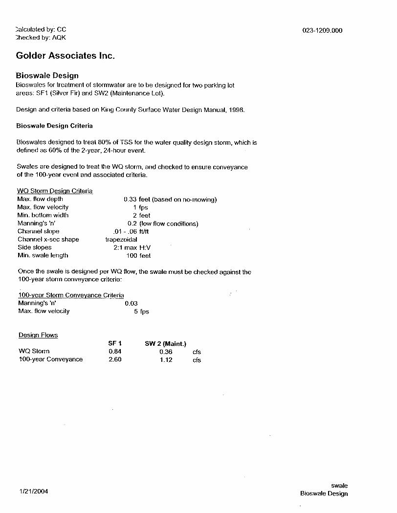
3.3.3 B3 - Bioswale at Discharge
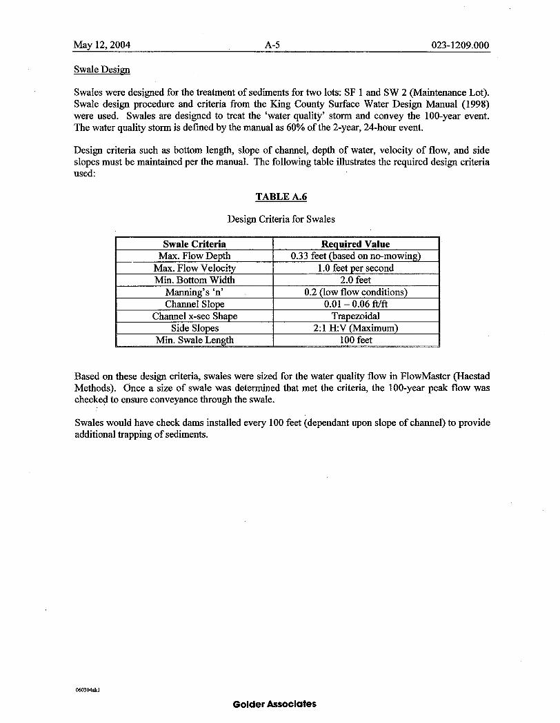
Where space is available, a swale with rock check dams would be installed to further address suspended sediments and reduce velocities at the discharge location. Bioswales would be included at the discharge locations for either the B1 or B2 treatment trains. Bioswale designs are based on the water quality and conveyance criteria outlined in the King County Surface Water Design Manual (1998). Bioswales would be vegetated with native grasses, shrubs, and trees. Final determination of vegetative types would be determined in the final design (pending USFS Botanist approval). Selection of grass/shrub/tree types would recognize that establishing new vegetation at the site can be difficult and may take some time to establish sustainable plant communities.
Refer to the B3 conceptual cross-section in Drawing 1000.
3.3.4 E1 - Enhanced Water Quality and Quantity Treatment Train
The E1 treatment train includes the components discussed for the B2 treatment train (as discussed in Section 3.3.2). In addition, detention vaults would be utilized to maintain and/or restore in-stream flows.
The E1 treatment train consists of (in series) paved parking lot areas; catch basins collecting and routing flows as well as acting as a sediment trap; oil-water separators (OWSs); routing to detention vaults; and discharge to designated areas.
A detention vault would be designed and installed to treat increases in the water quantity, as outlined in Section 2.0, and Table 2-1. Detention vaults would be located within the perimeter limits of parking lot areas. The conceptual design assumes standard pre-cast vault sections with an approximate 20-foot width and a 6-foot inside depth. Pre-cast vault sections were selected to minimize overall costs and simplify construction installation. Refer to Appendix A for conceptual design calculations and Appendix B for typical schematics of vault structures.
Refer to the E1 conceptual cross-section in Drawing 1000.
Appendix G: Conceptual Stormwater Management Plan
The Summit-at-Snoqualmie Master Development Plan Proposal
Final Environmental Impact Statement G-7
3.4 Parking Lot Grading Alternatives
All parking lot areas discussed in this document would be paved, providing the opportunity to collect and route surface drainage as needed. Management of snow accumulations is important to the continued viability of the operation of the ski area, and therefore grading of the parking lots would be done to generally maximize snow storage and direct run-off and snow melt to open areas away from snow storage areas. In general, snow storage areas are located along the perimeter of the parking lots.
Two conceptual grading approaches are proposed for paved parking lot areas. The first approach involves reverse crowning of the lot in the center, providing graded slopes (approx. 2%) to drain areas from the outside perimeter towards the center of the lot where manholes would collect and convey the water. This approach would work better for smaller or narrow parking lots where graded surface areas sloped towards catch basins are less than approximately 100 feet.
The second approach would be to crown and grade slopes to drain away from the center of the lot to catch basins located just inside the perimeter of the lot. This approach would most likely work better in larger parking lots where it is not possible to drain surface water across long open areas, or distances between catch basins are greater than approximately 100 feet.
Refer to Drawing 1010 for typical grading sections. Final determination of grading for paved parking lot areas would be made at the time of final SMP design.
3.5 Proposed Conceptual Stormwater Facility Designs/Recommendations
This section summarizes the proposed conceptual stormwater design recommendations for each of the targeted parking lot areas.
3.5.1 Silver Fir Lot
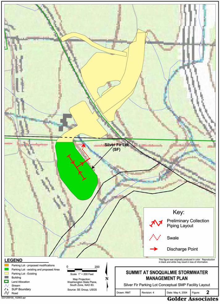
Silver Fir (SF) Lot 1 at Summit East is located just below the Silver Fir chairlift (refer to Figures 1 and 2).1 SF Lot 1 is located on both private and public land. The entire lot would be paved and incorporate stormwater management. The SF Lot would be paved to reduce the transport of fine grained sediments off-site. The lot would not be increased in size, and therefore no water quantity treatment is proposed. The B2 and B3 treatment train is proposed for this lot. The paved area would be graded per the approach outlined above in Section 3.4. Collected drainage would be routed to the east side of the lot into a swale that would run south to north along an existing shelf of ground (refer to Figure 2). The swale would discharge into the adjacent stream via an armored rock pad.
3.5.2 Summit West Lot 2
The Summit West Lot 2 (SW2) is located between the maintenance building and the main rental lodge at Summit West (refer to Figures 1 and 3). The SW2 Lot would be paved to reduce the transport of fine grained sediments off-site.
The SW2 Lot is proposed to be broken into three sub-catchment areas (refer to Figure 3): SW2-maint. referring to the area immediately surrounding the maintenance shop at the south end of SW2; SW2-south including the approximate upper half of SW2 extending from the maintenance shop downslope; and SW2- north including the approximate lower half of SW2 down to the rental lodge. The combined area 1 The USFS approved the upgrade of the Silver Fir chairlift to a detachable quad in a Categorical Exclusion in 2008. While the Silver Fir chairlift has not yet been replaced as of this FEIS, the replacement and realignment of the chairlift is considered an existing condition in this FEIS analysis.

Appendix G: Conceptual Stormwater Management Plan
The Summit-at-Snoqualmie Master Development Plan Proposal
Final Environmental Impact Statement G-8
of SW2-maint. + SW2-south + SW2-north = SW2, and would not increase in size from the existing condition, and therefore no water quantity treatment is proposed. SW2-maint. represents a small area in the immediate vicinity around the maintenance shop. The SW2-north and SW2-south catchment areas make up the majority of the SW2 parking lot.
All paved areas would be graded per the approach outlined above in Section 3.4. The B2 and B3 treatment train is proposed for SW2-maint. The swale for SW2-maint would be located along the east side of the maintenance shop. The B2 treatment train is proposed for SW2-south and SW2-north. Collected drainage from these two sub-catchment areas would be routed to the north (downslope) and discharged into an existing 36-inch corrugated metal pipe (CMP) located along the west edge of the highway (Figure 3).
3.5.3 Summit West Lot 1
Summit West Lot 1 (SW1) is located just east of the main rental lodge at Summit West (refer to Figures 1 and 3). The SW1 Lot currently consists of three levels. There is an existing drainage ditch located between the lower two parking areas that drains to the north towards Interstate-90. The Summit plans to re-grade the upper two parking areas to create one large area, while leaving the lower elevation area in the same configuration. All final parking areas would be paved to reduce the transport of fine grained sediments off-site. All paved areas would be graded per the approach outlined above in Section 3.4.
The re-grading would result in two final parking levels, called SW1-upper and SW1-lower (refer to Figure 3). SW1-upper would include the combined area of the two previous upper parking areas, and SW1-lower would include the area of the existing lower lot area.
SW1-upper would increase in size, and therefore treatment is proposed for the increased quantity of water resulting from the larger surface area. The E1 treatment train is proposed for SW1-upper. The detention vault is proposed to be installed within the perimeter of SW1-upper. Discharge from the vault would be routed into the drainage ditch just to the east of the vault (Figure 3). Refer to Appendix A for preliminary design calculations.
The SW1-lower lot would not change in size and therefore no water quantity treatment is proposed. The B2 treatment train is proposed for SW1-lower. Collected drainage from SW1-lower would be routed to the east side of the same lot and discharged into an existing CMP (Figure 3).
3.5.4 Alpental Lot 3
The Alpental Lot 3 (A3) is located on the east side of the Upper South Fork Snoqualmie River, across from the Alpental Lodge (refer to Figures 1 and 4). The A3 Lot would be paved to reduce the transport of fine grained sediments off-site. A3 would not increase in size from the existing condition, and therefore no water quantity treatment is proposed. The B2 treatment train is proposed for A3.
All paved areas would be graded per the approach outlined above in Section 3.4. Collected drainage would be routed to the south side of the parking lot and discharged into an existing ravine which eventually drains into the South Fork Snoqualmie (Figure 4).
3.5.5 Alpental Lot 4
The Alpental Lot 4 (A4) is located on the west side of the Upper South Fork Snoqualmie River, immediately north of the Alpental Lodge (refer to Figures 1 and 4). The A4 Lot would be paved to reduce the transport of fine grained sediments off-site. A4 would not increase in size from the existing

Appendix G: Conceptual Stormwater Management Plan
The Summit-at-Snoqualmie Master Development Plan Proposal
Final Environmental Impact Statement G-9
condition, and therefore no water quantity treatment is proposed. The B2 treatment train is proposed for A4.
All paved areas would be graded per the approach outlined above in Section 3.4. Collected drainage would be routed to the east side of the parking lot and tightlined along the Alpental road to a central discharge point at the bridge crossing of the Upper South Fork Snoqualmie River between Alpental Lots 3 and 7 (refer to Figure 4). A tightline is a conveyance pipe that is intended to transport stormwater from one location to another.
3.5.6 Alpental Lot 5
The Alpental Lot 5 (A5) is located on the west side of the Upper South Fork Snoqualmie River, north of the Alpental Lodge and Lot A4 (refer to Figures 1 and 4). The A5 Lot would be paved to reduce the transport of fine grained sediments off-site. A5 would not increase in size from the existing condition, and therefore no water quantity treatment is proposed. The B2 treatment train is proposed for A5.
All paved areas would be graded per the approach outlined above. Collected drainage would be routed to the east side of the parking lot and tightlined along the Alpental road to a central discharge point at the bridge crossing of the Upper South Fork Snoqualmie River between Alpental Lots 3 and 7 (refer to Figure 4).
3.5.7 Alpental Lot 6
For Lot 6, snow management strategies are proposed in tandem with stormwater management design. In addition to the stormwater facilities recommended below, suggested snow management strategies are also recommended for Lot 7 and discussed further in Section 4.0.
Alpental Lot 6 (A6) is the most northern parking lot at the Alpental ski area (Figure 1 and 4). A6 would be paved to reduce the transport of fine grained sediments off-site. A6 would not increase in size from the existing condition, and therefore no water quantity treatment is proposed. The B2 treatment train is proposed for A6.
All paved areas would be graded per the approach outlined above. Collected drainage would be routed to the south end of the parking lot to a switch structure (refer to Section 4.1.3) that would direct flows either to the snow storage pond or to a tightline under the Alpental road for discharge at the bridge crossing of the Upper South Fork Snoqualmie River between Alpental Lots 3 and 7 (refer to Figure 4).
Refer to Section 4.1.3 for a description of the proposed pond and switch structure.
3.5.8 Alpental Lot 7
The Alpental Lot 7 (A7) is located on the east side of the Upper South Fork Snoqualmie River, north of the Alpental Lodge and Lot A3 (refer to Figures 1 and 4). The A7 Lot would be paved to reduce the transport of fine grained sediments off-site. A7 would not increase in size from the existing condition, and therefore no water quantity treatment is proposed. The B2 treatment train is proposed for A7.
All paved areas would be graded per the approach outlined above in Section 3.4. Collected drainage would be routed to the east side of the parking lot and tightlined along the Alpental road to a central discharge point at the bridge crossing of the Upper South Fork Snoqualmie River, downstream of A7 (refer to Figure 4).

Appendix G: Conceptual Stormwater Management Plan
The Summit-at-Snoqualmie Master Development Plan Proposal
Final Environmental Impact Statement G-10
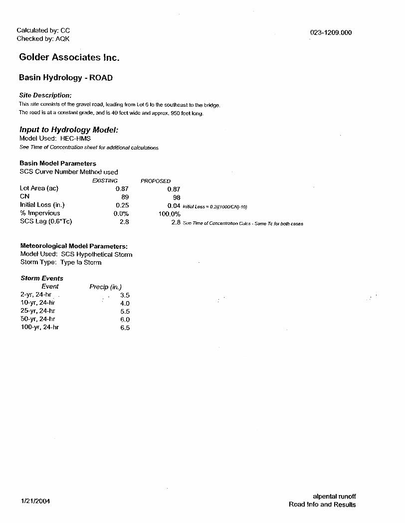
3.5.9 Alpental Road
The road that provides access to the Alpental parking lots is also considered in this SMP. The road is proposed to be paved to reduce the transport of sediments off-site (Figure 1 and 4). The road would not be widened or otherwise increased in size, therefore water quantity control is not proposed.
The road would be crowned with a minimum 2 percent slope to either side of the centerline to provide drainage to the sides of the roadway. The B2 treatment train is proposed for road areas. Runoff would be directed into catch basins located along the sides of the roadway, routed through OWS’s and then discharged to the South Fork Snoqualmie River. The preliminary discharge location is in the vicinity of the bridge over the South Fork Snoqualmie River (Figure 4). The final discharge location would be determined in the final design.
Appendix G: Conceptual Stormwater Management Plan
The Summit-at-Snoqualmie Master Development Plan Proposal
Final Environmental Impact Statement G-11
4.0 SNOW MANAGEMENT
Managing snow represents one of the biggest challenges in the operation of a ski area and design of a stormwater management plan for cold climates (CWP, 1997). The following proposals for snow management are based on review of available cold weather climate literature (CWP, 1997), (NCCG, 1997), and discussions with SE the Summit staff.
4.1 Proposed Strategies
Snow storage opportunities were evaluated for the parking areas addressed by this report. The A6 lot at Alpental was identified as having the most potential for developing additional snow storage. The following discussion outlines recommendations for optimizing snow storage at A6 to maximize parking efficiency. This action would not expand the parking area, but would provide additional snow storage capacity along the perimeter of the lot, thereby opening up parking space within the lot itself.
4.1.1 Creek Shelf Removal at Parking Lot A6
A small stream discharges off the steep slopes above Lot A6 and A5 on the west side of the lots (Figure 4). The stream takes an abrupt turn onto a shelf of fill material and flows along the top of the shelf around the north end of lot A6 before flowing into the South Fork Snoqualmie River. The shelf is not a natural feature, and appears to have been constructed for the purpose of diverting the stream around lot A6. Currently this area is used as a ski trail during winter. The existing shelf provides a base for the trail.
The proposal calls for changing the alignment of the stream starting at the point where it currently drops onto the shelf (at the edge of the parking lot). The stream would be re-aligned to flow to the south to lot A5 (Figure 4). The shelf along the west edge of lot A6 would be excavated to match the adjacent upslope area (refer to Drawing 1020 for a typical cross-section). The fill excavated from the shelf would be spread across the parking lot and/or be used to complete the final grading plan for the parking lot. We assume that the soil materials comprising the shelf would be suitable for use in constructing and grading the parking lot areas. Soil sampling and analysis would be completed in support of the final design.
The space previously occupied by the shelf would be used as snow storage for snow removed from the A6 parking lot (approximately 0.75 acre). Trail access would be maintained by grooming the snow flat to provide a trail surface each time snow is deposited. We anticipate that the skier trail would therefore change in elevation as snow is added into storage or as snow melts. The trail would remain accessible and function throughout the operation ski season.
4.1.2 Access Ramp Removal between A6 and A5
Lots A6 and A5 are connected by an access ramp that runs between the south end of Lot 6 down to the north end of A5 (Figure 4). This access ramp is used during the summer months, and is typically covered with snow in the winter months. This ramp is proposed for removal, creating additional snow storage areas accessible from both A6 and A5 (approximately 0.25 acre). The excavated slope where the ramp would be removed would be graded to a stable slope angle (maximum slope of 2H:1V) and covered with an erosion resistant quarry spalls armor layer of riprap. We assume that the soil materials comprising the ramp would be suitable for use in constructing and grading the parking lot areas. Soil sampling and analysis would be completed in support of the final design. Refer to Drawing 1030 for a typical cross-section.

Appendix G: Conceptual Stormwater Management Plan
The Summit-at-Snoqualmie Master Development Plan Proposal
Final Environmental Impact Statement G-12
4.1.3 A6/A5 Pond and Switch
The excavation of the access ramp between lots A6 and A5 discussed in the previous section offers the opportunity to provide a large snow storage area. To further increase the volume of available snow storage, the bottom of the ramp area would be over-excavated to create a shallow pond. Stormwater runoff from A6 would be routed to the pond through a ‘switch’ control structure (Figure 4). The stormwater flowing through the pond could have the secondary benefit of accelerating snow melt.
This alternative is proposed as a pilot program. There are uncertainties regarding the performance of the pond to increase melting of stored snow, and there may be modifications necessary at a later date to optimize the performance of the structure. Monitoring guidelines are addressed in the monitoring portion of the Summit at Snoqualmie MDP – Implementation, Operation, Restoration and Monitoring Plan (SE GROUP, 2004). Final details would be addressed in the final design.
The extent of melting is unknown at this time, and would be heavily influenced by temperature and precipitation conditions. The switch would consist of a manhole structure with inlet and outlet piping located at elevations that would automatically direct flows to the pond during normal operation, and direct flows around the pond if it is full or frozen. Flows that pass through the pond would be routed to the discharge point at Lot A7 at the bridge crossing of the South Fork at the River along Alpental road between Lots 3 and 7. Flows that are directed around the pond would also be routed to the discharge point at Lot A7 at the bridge crossing of the South Fork at the River along Alpental road between Lots 3 and 7.
Final switch piping elevations and piping layout would be completed in the final design. Refer to Drawing 1030 for a typical conceptual plan view and cross-sections.

Appendix G: Conceptual Stormwater Management Plan
The Summit-at-Snoqualmie Master Development Plan Proposal
Final Environmental Impact Statement G-13
5.0 CLOSURE
The report has been prepared exclusively for the use of the Summit at Snoqualmie, USFS and consultants for specific application to the DEIS for the Summit at Snoqualmie MDP. The information presented in this report is based on the available data and generally accepted standard of practice engineering principles. The recommendations presented herein outline a conceptual stormwater plan that is based on assumptions corresponding to the available data as outlined in the report. Development of a final stormwater plan would require confirmation of site conditions, completion of final design calculations, development of final design layouts, and development of specifications to support construction and a stamp by a Professional Engineer. Final design would require additional site specific topographic survey information detailing the elevations and locations of pertinent features of the parking lot areas discussed in this report. The recommendations presented herein are not intended to nor should they be construed to represent a warranty. We recommend that Golder be consulted if any changes to the recommendations are required, or if conditions encountered in the field are different than anticipated.

Appendix G: Conceptual Stormwater Management Plan
The Summit-at-Snoqualmie Master Development Plan Proposal
Final Environmental Impact Statement G-14
6.0 REFERENCES
Center for Watershed Protection (CWP), 1997, Stormwater BMP Design Supplement for Cold Climates, Prepared for US EPA Office of Wetlands, Oceans and Watersheds and US EPA Region 5.
Hydraulic Engineering Center Hydrologic Modeling System (HEC-HMS), U.S. Army Corps of Engineers, Version 2.2.1, http://www.hec.usace.army.mil/software/hec-hms/hechms-hechms.html.
King County Surface Water Design Manual (KCSWDM), 1998, http://dnr.metrokc.gov/wlr/dss/manual.htm .
Northwest Colorado Council of Governments (NCCG), 1997, Water Quality Protection Standards, Version: 12/30/1997.
USDA, 1990a. MBSNF LRMP.
USDA, 1990b. OWNF LRMP.
USDA, USDI, 1994. Northwest Forest Plan
USDA, USDI. 2004. Record of Decision Amending Resource Management Plans for Seven Bureau of Land Management Districts and Land and Resource Management Plans for Nineteen National Forests Within the Range of the Northern Spotted Owl: Decision to Clarify Provisions Relating to the Aquatic Conservation Strategy. U.S. Department of Agriculture.
Western U.S. Precipitation Frequency Maps, National Oceanic Atmospheric Administration (NOAA) Atlas 2, ( http://www.wrcc.dri.edu/pcpnfreq.html )

Appendix G: Conceptual Stormwater Management Plan
FIGURES


Appendix G: Conceptual Stormwater Management Plan
DRAWINGS


Appendix G: Conceptual Stormwater Management Plan
APPENDIX A
CONCEPTUAL DESIGN CALCULATIONS