appendix - quality transmission componentsqtcgears.com/tools/catalogs/pdf_q420/appendix.pdf · a2...
TRANSCRIPT

Reference Materials
A1
APPENDIXTable of Contents
Page Gear Materials ...................................................................................................................................................................................... A2 1.1 Carbon Tool Steels and Alloy Steels (JIS Material Symbol) .......................................................................................... A2 1.2 Symbol System for JIS Material ................................................................................................................................... A2 1.3 Method of Hardening..................................................................................................................................................... A2 Hardness Comparison Table ............................................................................................................................................................... A3 Common Deviations of Hole Dimensions .......................................................................................................................................... A4 Common Deviations of Shaft Dimensions ......................................................................................................................................... A6
Root Diameter for Metric Coarse Threads ......................................................................................................................................... A8
Dimensions of Counterbores and Bolt Holes for Hexagon Socket Head Cap Screws .................................................................. A9
Straight-sided Splines ......................................................................................................................................................................... A10 The Surface Strength of Spline ........................................................................................................................................................... A11
Flat Keys and Keyways ........................................................................................................................................................................ A12 Comparative Table for Gear Pitch and Module .................................................................................................................................. A13
Center Holes ......................................................................................................................................................................................... A14
Permissible Machining Deviations in Dimensions without Tolerance Indication .......................................................................... A15
Permissible Deviations in Dimensions without Tolerance Indication for Injection Model Products ........................................... A15
Geometrical Characteristic Symbol .................................................................................................................................................... A15
Cylindrical Gears: ISO System of Accuracy ..................................................................................................................................... A16
Precision Standard for Bevel Gears ................................................................................................................................................... A22
Backlash Standard for Spur and Helical Gears ................................................................................................................................. A24
Backlash Standard for Bevel Gears ................................................................................................................................................... A25
Tolerance of Center Distance for Spur and Helical Gears ................................................................................................................ A26
Shaft Parallelism of Spur and Helical Gears ...................................................................................................................................... A26
1
2
3
4
5
6
7
8
9
10
11
12
13
14
15
16
17
18
19
20

A2
Reference Materials
The following symbol SNCM420(H) is an example of JIS code system of corbon tool steel and alloy steel:
S NCM 4 20 H
333333
3335
1.1 Carbon Tool Steels and Alloy Steels (JIS Material Symbol)
1 Gear Materials
Carbon (C)content (%)
0.13~0.18
0.17~0.23
0.22~0.28
0.27~0.35
0.32~0.40
0.36~0.43
0.40~0.50
0.44~0.53
JIS Material symbol Tensilestrengthkgf/mm2
>080>085>080>100>090>110
>085>095>100>095>100
>095
>080>085>090>085
>090>095>075>095
>100>100>100
>100>105
>105
Elogation%
or more151617121612
1414141715
18
18181618
15152215
131216
1212
14
Reduction of area
%or more
404045454540
3540354545
50
55555050
50505045
454545
4040
40
Brinellhardness
HB
217~302235~321217~321285~388255~341311~375
235~321262~341285~363248~341293~375
269~321
229~285241~293255~321248~302
255~311269~321212~255269~321
269~321285~341293~352
285~341302~363
302~363
Endurance limit (N x 107)kgf/mm2
Rotatingbeam test
283028353138
3033353335
33
28303130
31332633
353535
3537
37
Torsion test
171917222024
1921222122
21
18192019
20211621
222222
2223
23
Tension &compression
262826332936
2831333133
31
26282928
29312431
35
New standardSCr415(H)SCM415(H)SNC415(H)SNC815(H)SNCM415SNCM815
SCr420(H)SCM420(H)SCM421SNCM220(H)SNCM420(H)
SNCM625
SCr430(H)SCM430SCM432SNC631(H)
SCr435(H)SCM435(H)SNC236SNC836
SCr440(H)SCM440(H)SNCM439
SCr445SCM445(H)
SNCM447
Old standardSCr21(H)SCM21(H)SNC21(H)SNC22(H)SNCM22SNCM25
SCr22(H)SCM22(H)SCM23SNCM21(H)SNCM23(H)
SNCM2
SCr2(H)SCM2SCM1SNC2(H)
SCr3(H)SCM3(H)SNC1SNC3
SCr4(H)SCM4(H)SNCM8
SCr5SCM5(H)
SNCM9
1.2 Symbol System for JIS Material 1.3 Method of Hardening
Represents the steel family.Symbols of the major alloy element content.
Represents the value of the carbon content.
Code no. of the major alloy element content amount.
Additional symbol
The strength and the hardness of the gear surface may be increased after suitable heat treatment is done. The kind of heat treatment varies with the carbon content of the steel used for the gear.
Quenching Method
Carburizing Quenching
Furnace Hardening
Induction Hardening
Flame Hardening
Nitriding ( NOTE 1)
Carbon(C)%0 0.1 0.2 0.3 0.4 0.5
NOTE1. For the nitriding process, more than one of Al, Cr Mo and V alloy elements must be present in the steel.

Reference Materials
A3
2 Hardness Comparison Table
Approximate Hardness Conversion of Steel Based on the Rockwell C Scale:HRC
Rockwell
C
hardness
6867666564
6362616059
5857565554
5352515049
4847464544
4342414039
3837363534
3332313029
2827262524
23222120
(18)
(16)(14)(12)(10)(8)
(6)(4)(2)(0)
HV
Vickers
hardness
940900865832800
772746720697674
653633613595577
560544528513498
484471458446434
423412402392382
372363354345336
327318310302294
286279272266260
254248243238230
222213204196188
180173166160
HBBrinell hardness
10mm Ball・Load 3000kgf
Standard ball
—————
—————
—————
—500487475464
451442432421409
400390381371362
353344336327319
311301294286279
271264258253247
243237231226219
212203194187179
171165158152
Hult-grenball
—————
———613599
587575561546534
519508494481469
455443432421409
400390381371362
353344336327319
311301294286279
271264258253247
243237231226219
212203194187179
171165158152
Tungsten-carbide
ball
———739722
705688670654634
615595577560543
525512496481469
455443432421409
400390381371362
353344336327319
311301294286279
271264258253247
243237231226219
212203194187179
171165158152
HRA
A ScaleLoad 60kgf
braleindenter
85.685.084.583.983.4
82.882.381.881.280.7
80.179.679.078.578.0
77.476.876.375.975.2
74.774.173.673.172.5
72.071.570.970.469.9
69.468.968.467.967.4
66.866.365.865.364.7
64.363.863.362.862.4
62.061.561.060.5—
—————
————
Rockwell hardness NOTE 2.
HRB
B ScaleLoad 100kgfDia. 1/16in
Ball
—————
—————
—————
—————
—————
—————
——
(109.0)(108.5)(108.0)
(107.5) (107.0)(106.0)(105.5)(104.5)
(104.0)(103.0)(102.5)(101.5)(101.0)
100.0099.0098.5097.8096.7
095.5093.9092.3090.7089.5
087.1085.5083.5081.7
HRD
D ScaleLoad 100kgf
braleindenter
76.976.175.474.573.8
73.072.271.570.769.9
69.268.567.766.966.1
65.464.663.863.162.1
61.460.860.059.258.5
57.756.956.255.454.6
53.853.152.351.550.8
50.049.248.447.747.0
46.145.244.643.843.1
42.141.640.940.1—
—————
————
HS
Shor
e ha
rdne
ss
9795929188
8785838180
7876757472
7169686766
6463626058
5756555452
5150494847
4644434241
4140383837
3635353433
3231292827
26252424
Tensile Strengthkgf/mm2
(N/mm2)Aprox. value
NOTE 1.
—————
—————
———
212 {2079}205 {2010}
199 {1952}192 {1883}186 {1824}179 {1755}172 {1687}
167 {1638}161 {1579}156 {1530}151 {1481}146 {1432}
141 {1383}136 {1334}132 {1294}127 {1245}124 {1216}
120 {1177}118 {1157}114 {1118}110 {1079}108 {1059}
105 {1030}102 {1000}100 {0981}097 {0951}095 {0932}
093 {0912}090 {0883}088 {0863}086 {0843}084 {0824}
082 {0804}080 {0785}079 {0775}077 {0755}075 {0736}
072 {0706}069 {0677}066 {0647}063 {0618}061 {0598}
059 {0579}056 {0549}054 {0530}053 {0520}
HRCRockwell
C Hardness
NOTE 2.
6867666564
6362616059
5857565554
5352515049
4847464544
4342414039
3837363534
3332313029
2827262524
23222120
(18)
(16)(14)(12)(10)(8)
(6)(4)(2)(0)
Approx. hardness
of
principal materials
S45C soft nitriding
SCM415 case hardening
SCM440 induction hardening
S45C induction hardening
SCM415 core hardness
S45C core hardness
SUS303
REMARK: The boldfaced figures are based on ASTM E 140 Table 3 (SAE-ASM-ASTM)NOTE 1: Approximate values were determined from "Conversion Tables" of JIS Z 8413 and Z 8438. The units and values in parentheses{ } are based on International System of Units (SI). These are shown for reference. Note that 1N/mm2=1MPa.NOTE 2: The parenthesized values in the table are not used so frequently.
S45C thermal refining
SCM440 core hardness
A4
Reference Materials
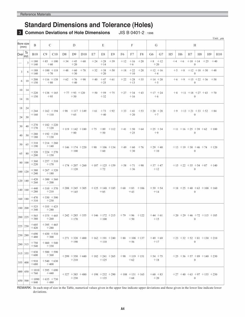
Standard Dimensions and Tolerance (Holes)
F
024018
3 Common Deviations of Hole Dimensions JIS B 0401-2 : 1998
Unit: μm
Bore size(mm)
Over
—
Toincl.
003
B
B10
+1800+1400
C
C9
+8500+100+60
C10
D
D8
+3400+4500+60+20
D9 D10
E
E7
+2400+2800+39+14
E8 E9 F6
+1200+1600+20+60
F7 F8
G
G6
+800+12+20
G7
H
H5
003 006 +1880+1400
+1000+118+70
+4800+6000+78+30
+3200+3800+50+20
+1800+2200+28+10
+120+16+4
006 010 +2080+1500
+1160+138+80
+6200+7600+98+40
+4000+4700+61+25
+2200+2800+35+13
+140+20+5
010 014+2200+1500
+1380+165+95
+770+930+120+500
+5000+5900+75+32
+2700+3400+43+16
+170+24+6
014 018
+2440+1600
+1620+194+110
+9800+1170+149+650
+6100+7300+92+40
+3300+4100+53+20
+200+28+7
024 030
030 040 +2700+1700
+1820+220+120 +1190+1420+180
+800+7500+8900+112
+500+4100+5000+64
+25+250+34
+9040 050 +2800
+1800+1920+230
+130
050 065 +3100+1900
+2140+260+140 +1460+1740+220
+100+9000+1060+134
+600+4900+6000+76
+30+290+40
+10065 080 +3200
+2000+2240+270
+150
080 100 +3600+2200
+2570+310+170 +1740+2070+260
+120+1070+1250+159
+720+5800+7100+90
+36+370+47
+12100 120 +3800
+2400+2670+320
+180
120 140 +4200+2600
+3000+360+200
+2080+2450+305+145
+1250+1480+185+850
+6800+8300+106+430
+390+54+14
140 160 +4400+2800
+3100+370+210
160 180 +4700+3100
+3300+390+230
180 200 +5250+3400
+3550+425+240
+2420+2850+355+170
+1460+1720+215+100
+7900+9600+122+500
+440+61+15
200 225 +5650+3800
+3750+445+260
225 250 +6050+4200
+3950+465+280
250 280 +6900+4800
+4300+510+300 +2710+3200+400
+190+1620+1910+240
+110+8800+1080+137
+560+490+69
+17280 315 +7500
+5400+4600+540
+330
315 355 +8300+6000
+5000+590+360 +2990+3500+440
+210+1820+2410+265
+125+9800+1190+151
+620+540+75
+18355 400 +9100
+6800+5400+630
+400
400 450 +1010+7600
+5950+690+440 +3270+3850+480
+230+1980+2320+290
+135+1080+1310+165
+680+600+83
+20
+400+600+100+1400+2500+400
+500+800+120+180+3000+480
+600+900+150+220+3600+580
+800+110+180+270+4300+700
+900+130+210+330+5200+840
+110+160+250+390+6200+1000
+130+190+300+460+7400+1200
+150+220+350+540+8700+1400
+180+250+400+630+1000+1600
+200+290+460+720+1150+1850
+230+320+520+810+1300+2100
+250+360+570+890+1400+2300
+270+400+630+970+1550+2500
450 500 +1090+8400
+6350+730+480
H6 H7 H8 H9 H10
REMARK: In each step of size in the Table, numerical values given in the upper line indicate upper deviations and those given in the lower line indicate lower deviations.

Reference Materials
A5
M
REMARK: In each step of size in the Table, numerical values given in the upper line indicate upper deviations and those given in the lower line indicate lower deviations.
Unit: μm
Over
—
Toincl.
003
JS
JS5
±02.50
JS6
K
JS7
±0300.
K5 K6 K7 M5 M6 M7 N6 N7 P6 P7 R7 S7 T7 U7
±0500.
N
+00-04
+00-06
+00-10
-02-06
-02-08
-02-12
-04-10
-04-14
-06-12
-006-016
-010-020
-014-024
— -018-028
3 006 ± 2.50 ±0400. ±0600. +00-05
+02-06
+03-09
-03-08
-01-09
+00-12
-05-13
-04-16
-09-17
-008-020
-011-023
-015-027
— -019-031
6 010 ±03.50 ±04.50 ±07.50 +01-05
+02-07
+05-10
-04-10
-03-12
+00-15
-07-16
-04-19
-12-21
-009-024
-013-028
-017-032
— -022-037
10 014
±04.50 ±05.50 ±0900.+02-06
+02-09
+06-12
-04-12
-04-15
+00-18
-09-20
-05-23
-15-26
-011-029
-016-034
-021-039
—-026-044
14 018
18 024
±04.50 ±06.50 ± 10.5+01-08
+02-11
+06-15
-05-14
-04-17
-00-21
-11-24
-07-28
-18-31
-014-035
-020-041
-027-048
— -033-054
24 030 -033-054
-040-061
30 040
±05.50 ±0800. ± 12.5+02-09
+03-13
+07-18
-05-16
-04-20
+00-25
-12-28
-08-33
-21-37
-017-042
-025-050
-034-059
-039-064
-051-076
40 050 -045-070
-061-086
50 065
±06.50 ±09.50 ± 150.+03-10
+04-15
+09-21
-06-19
-05-24
-00-30
-14-33
-09-39
-26-45
-021-051
-030-060
-042-072
-055-085
-076-106
65 080 -032-062
-048-078
-064-094
-091-121
80 100
±07.50 ± 110. ± 17.5+02-13
+04-18
+10-25
-08-23
-06-28
-00-35
-16-38
-10-45
-30-52
-024-059
-038-073
-058-093
-078-113
-111-146
100 120 -041-076
-066-101
-091-126
-131-166
120 140
±0900. ± 12.5 ± 200.+03-15
+04-21
+12-28
-09-27
-08-33
-00-40
-20-45
-12-52
-36-61
-028-068
-048-088
-077-117
-107-147
—140 160 -050-090
-085-125
-119-159
160 180 -053-093
-093-133
-131-171
180 200
± 100. ± 14.5 ± 230.+02-18
+05-24
+13-33
-11-31
-08-37
-00-46
-22-51
-14-60
-41-70
-033-079
-060-106
-105-151
— —200 225 -063-109
-113-159
225 250 -067-113
-123-169
250 280
± 11.5 ± 160. ± 260.+03-20
+05-27
+16-36
-13-36
-09-41
-00-52
-25-57
-14-66
-47-79
-036-088
-074-126
— — —
280 315 -078-130
315 355
± 12.5 ± 180. ± 28.5+03-22
+07-29
+17-40
-14-39
-10-46
-00-57
-26-62
-16-73
-51-87
-041-098
-087-144
— — —
355 400 -093-150
400 450
± 13.5 ± 200. ± 31.5+02-25
+08-32
+18-45
-16-43
-10-50
-00-63
-27-67
-17-80
-55-95
-045-108
-103-166
— — —
450 500 -109-172
P R S T U
X7
-20-30
-24-36
-28-43
-33-51
-38-56
-46-67
-56-77
—
—
—
—
—
—
—
—
XBore size(mm)

A6
Reference Materials
010
f
4 Common Deviations of Shaft Dimensions JIS B 0401-2:1998
Unit: μm
Shaftdiameter(mm)
Over
—
Toincl.
003
b
b9
-140-165
c9
c d
d8
-060-085
d9 e7 e8 e9 f6 f7 f8 g4 g5 g6 h4 h5 h6 h7 h8 h9
-020-0340-045
e
-014-0240-0280-039
-1080-0060-108-0120-0160-020
-02-050-060-08
0-03 -04 -06 -10 -14 -025
003 006 -140-170
-070-100
-030-0480-60
-020-0320-0380-050
-1080-0100-108-0180-0220-028
-04-080-090-12
0-004 -05 -08 -12 -18 -030
006 010 -150-186
-080-116
-040-0620-076
-025-0400-0470-061
-1080-0130-108-0220-0280-035
-05-090-110-14
0-04 -06 -09 -15 -22 -038
014-150-193
-095-138
-050-0770-093
-032-0500-0590-075
-1080-0160-108-0270-0340-043
-06-110-140-17
0-05 -08 -11 -18 -27 -043
014 018
018 024-160-212
-110-162
-065-0980-117
-040-0610-0730-092
-1080-0200-108-0330-0410-053
-07-130-160-20
0-06 -09 -13 -21 -33 -052
024 030
030 040 -170-232
-120-182 -080
-1190-142-050
-0750-0890-112-1080-0250-108-0410-0500-064
-09-160-200-25
0-07 -11 -16 -25 -39 -062
040 050 -180-242
-130-192
050 065 -190-264
-140-214 -100
-1460-174-060
-0900-1060-134-1080-0300-108-0490-0600-076
-10-180-230-29
0-08 -13 -19 -30 -46 -074
065 080 -200-274
-150-224
080 100 -220-307
-170-257 -120
-1740-207-072
-1070-1260-159-1080-0360-108-0580-0710-090
-12-220-270-34
0-10 -15 -22 -35 -54 -087
100 120 -240-327
-180-267
120 140 -260-360
-200-300
-145-2080-245
-085-1250-1480-185
-1080-0430-108-0680-0830-106
-14-260-320-39
0-12 -18 -25 -40 -63 -100
140 160 -280-380
-210-310
160 180 -310-410
-230-330
180 200 -340-455
-240-355
-170-2420-285
-100-1460-1720-215
-1080-0500-108-0790-0960-122
-15-290-350-44
0-14 -20 -29 -46 -72 -115
200 225 -380-495
-420-535
-540-670
-680-820
-840-995
-260-375
-280-395
-330-460
-400-540
-480-635
225 250
250 280 -480-610
-300-430 -190
-2710-320-110
-1620-1910-240-1080-0560-108-0880-1080-137
-17-330-400-49
0-16 -23 -32 -52 -81 -130
280 315
315 355 -600-740
-360-500 -210
-2990-350-125
-1820-2140-265-1080-0620-108-0980-1190-151
-18-360-430-54
0-18 -25 -36 -57 -89 -140
355 400
400 450 -760-915
-440-595 -230
-3270-385-135
-1980-2320-290-1080-0680-108-1080-1310-165
-20-400-470-60
0-20 -27 -40 -63 -97 -155
450 500
g h
REMARK: In each step of size in the Table, numerical values given in the upper line indicate upper deviations and those given in the lower line indicate lower deviations.

Reference Materials
A7
+32+ 5
+09
+ 1
—
Shaftdiameter(mm)
Unit: μm
Over
—
Toincl.
003
js
js4
±01.5
js5
k m
js6
±020.
js7 k4 k5 k6 m4 m5 m6 n6 p6 r6 s6 t6 u6 x6
±030.
n
±050. +03 +04-0
+06 +05 +06+02
+08 +10+04
+012+006
+016+010
+020+014
— +024+018
+26+20
3 006 ±02.5 ±02.5 ±040. ±060. +05 +06
+ 1+09 +08
-09+09+04
+12 +16+08
+020+012
+023+015
+027+019
— +031+023
+36+28
6 010 ±020. ±030. ±04.5 ±07.5 +05 +07
+ 1+10 +10 +12
+06+15 +19
+10+024+015
+028+019
+032+023
— +037+028
+43+34
10 014
±02.5 ±040. ±05.5 ±090.+06 +12 +12 +15
+07+18 +23
+12+029+018
+034+023
+039+028
—+044+033
+51+40
14 018 +56+45
18 024
±030. ±04.5 ±06.5 ± 10.5+08 +11
+ 2+15 +14 +17
+ 8+21 +28
+15+035+022
+041+028
+048+035
— +054+041
+67+54
24 030 +054+041
+061+048
+77+64
30 040
±03.5 ±05.5 ±080. ± 12.5+09 +13
+ 2+18 +16 +20
+ 9+25 +33
+17+042+026
+050+034
+059+043
+064+048
+076+060
—
40 050 +070+054
+086+070
50 065
±040. ±06.5 ±09.5 ± 150.+10 +15
+ 2+21 +19 +24
+11+30 +39
+20+051+032
+060+041
+072+053
+085+066
+106+087
—
65 080 +062+043
+078+059
+094+075
+091+121
80 100
±050. ±07.5. ± 110. ± 17.5+13 +18
+ 3+25 +23 +28
+13+35 +45
+23+059+037
+073+051
+093+071
+113+091
+146+124
—
100 120 +076+054
+101+079
+126+104
+166+144
120 140
±060. ±090. ± 12.5 ± 200.+15 +21
+ 3+28 +27 +33
+15+40 +52
+27+068+043
+088+063
+117+092
+147+122
— —140 160 +090+065
+125+100
+159+134
160 180 +093+068
+133+108
+171+146
180 200
±070. ± 100. ± 14.5 ± 230.+18 +24
+ 4+33 +31 +37
+17+46 +60
+31+079+050
+106+077
+151+122
— — —200 225 +109+080
+159+130
225 250 +113+084
+169+140
250 280
±080. ± 11.5 ± 160. ± 260.+20 +27
+ 4+36 +36 +43
+20+52 +66
+34+088+056
+126+094
— — — —
280 315 +130+098
315 355
±090. ± 12.5 ± 180. ± 28.5+22 +29
+ 4+40 +39 +46
+21+57 +73
+37+098+062
+144+108
— — — —
355 400 +150+114
400 450
± 100. ± 13.5 ± 200. ± 31.5+25 +45 +43 +50
+23+63 +80
+40+108+068
-166-126
— — —
450 500 -172-132
p r s t u x
REMARK: In each step of size in the Table, numerical values given in the upper line indicate upper deviations and those given in the lower line indicate lower deviations.

A8
Reference Materials
—
—
—
—
—
—
—
—
—
02.639
03.050
03.466
03.924
04.384
05.217
06.217
06.982
07.982
08.751
09.751
10.531
12.310
14.310
15.854
17.854
19.854
21.382
24.382
26.921
00.80
00.90
01.00
01.16
01.32
01.52
01.68
01.83
02.13
02.59
03.01
03.43
03.89
04.35
05.19
06.19
06.99
07.99
08.78
09.78
10.60
12.40
14.40
16.00
18.00
20.00
21.60
24.60
27.20
Thread
5 Root Diameter for Metric Coarse Threads JIS B 0205:1997
Unit: mm
Thread
M1
M1.1
M1.2
M1.4
M1.6
M1.8
M2
M2.2
M2.5
M3×0.5
M3.5
M4×0.7
M4.5
M5×0.8
M6
M7
M8
M9
M10
M11
M12
M14
M16
M18
M20
M22
M24
M27
M30
Outsidedia. d
01.000
01.100
01.200
01.400
01.600
01.800
02.000
02.200
02.500
03.000
03.500
04.000
04.500
05.000
06.000
07.000
08.000
09.000
10.000
11.000
12.000
14.000
16.000
18.000
20.000
22.000
24.000
27.000
30.000
PitchP
0.25
0.25
0.25
0.3
0.35
0.35
0.4
0.45
0.45
0.50
0.60
0.70
0.75
0.80
10.0
100.
1.25
1.25
1.50
1.50
1.75
200.
200.
2.50
2.50
2.50
300.
300.
3.50
(1)Height
ofthread
H1
0.135
0.135
0.135
0.162
0.189
0.189
0.217
0.244
0.244
0.271
0.325
0.379
0.406
0.433
0.541
0.541
0.677
0.677
0.812
0.812
0.947
1..083
1.083
1.353
1.353
1.353
1.624
1.624
1.894
Root diameter(2)
Series
100
00.73
00.83
00.93
01.08
01.22
01.42
01.57
01.71
02.01
02.46
02.85
03.24
03.69
04.13
04.92
05.92
06.65
07.65
08.38
09.38
10.10
11.80
13.80
15.30
17.30
19.30
20.80
23.80
26.20
95
00.74
00.84
00.94
01.09
01.24
01.44
01.59
01.74
02.04
02.49
02.88
03.28
03.73
04.18
04.97
05.97
06.71
07.71
08.46
09.46
10.20
11.90
13.90
15.40
17.40
19.40
20.90
23.90
26.40
90
00.76
00.86
00.96
01.11
01.26
01.46
01.61
01.76
02.06
02.51
02.92
03.32
03.77
04.22
05.03
06.03
06.78
07.78
08.54
09.54
10.30
12.10
14.10
15.60
17.60
19.60
21.10
24.10
26.6
85
00.77
00.87
00.97
01.12
01.28
01.48
01.63
01.79
02.09
02.54
02.95
03.36
03.81
04.26
05.08
06.08
06.85
07.85
08.62
09.62
10.40
12.20
14.20
15.70
17.70
19.70
21.20
24.20
26.80
80
00.78
00.88
00.98
01.14
01.30
01.50
01.65
01.81
02.11
02.57
02.98
03.39
03.85
04.31
05.13
06.13
06.92
07.92
08.70
09.70
10.50
12.30
14.30
15.80
17.80
19.80
21.40
24.40
27.00
75 70
00.81
00.91
01.01
01.17
01.33
01.53
01.70
01.86
02.16
02.62
03.05
03.47
03.93
04.39
05.24
06.24
07.05
08.05
08.86
09.86
10.70
12.50
14.50
16.10
18.10
20.10
21.70
24.70
0
27.3
65
00.82
00.92
01.02
01.19
01.35
01.55
01.72
01.88
02.18
02.65
03.08
03.51
03.97
04.44
05.30
06.30
07.12
08.12
08.94
09.94
10.80
12.60
14.60
16.20
18.20
20.20
21.90
24.90
27.50
60
00.84
00.94
01.04
01.21
01.37
01.57
01.74
01.91
02.21
02.68
03.11
03.55
04.01
04.48
05.35
06.35
07.19
08.19
09.03
10.03
10.90
12.70
14.70
16.40
18.40
20.40
22.10
25.10
27.70
(Reference)Inside diameter of inner thread
Min.tolerance
00.729
00.829
00.929
01.075
01.221
01.421
01.567
01.713
02.013
02.459
02.850
03.242
03.688
04.134
04.917
05.917
06.647
07.647
08.376
09.376
10.106
11.835
13.835
15.294
17.294
19.294
20.752
23.752
26.211
Max. tolerance
4H (M 1.4 or less)
5H (M 1.6 or more)
Grade 1
00.774
00.874
00.974
00.128
01.301
01.501
01.657
01.813
02.113
02.571
02.975
03.382
03.838
04.294
05.107
06.107
06.859
07.859
08.612
09.612
10.371
12.135
14.135
15.649
17.649
19.649
21.152
24.152
26.661
5H (M 1.4 or less)
6H(M1.6 or more)
Grade 2
00.785
00.885
00.985
01.142
01.321
01.521
01.679
01.838
02.138
02.599
03.010
03.422
03.878
04.334
05.153
06.153
06.912
07.912
08.676
09.676
10.441
12.210
14.210
15.744
17.744
19.744
21.252
24.252
26.771
7H
Grade 3
NOTE(1) H1=0.541266P
(2) Root diameter =d-2 × H1
Series100

Reference Materials
A9
6 Dimensions of Counterbores and Bolt Holes for Hexagon Socket Head Cap Screws JIS B 1176:1998
Unit: mm
d1
d'
D
(D' )
H
(H' )
(H'' )
M3
30. 40. 50. 060. 080. 100. 12 13.5 15.5 17.5 200. 220. 240. 27 30
3.4 4.5 5.5 06.6 090. 110. 14 160. 180. 200. 220. 240. 260. 30 33
5.5 70. 8.5 100. 130. 160. 18 210. 240. 270. 300. 330. 360. 40 45
6.5 80. 9.5 110. 140. 17.5 20 230. 260. 290. 320. 350. 390. 43 48
30. 40. 50. 060. 080. 100. 12 140. 160. 180. 200. 220. 240. 27 30
2.7 3.6 4.6 05.5 07.4 09.2 11 12.8 14.5 16.5 18.5 20.5 22.5 25 28
3.3 4.4 5.4 06.5 08.6 10.8 13 15.2 17.5 19.5 21.5 23.5 25.5 29 32
M4 M5 M6 M8 M10 M12 M14 M16 M18 M20 M22 M24 M27 M30
NOTE: The diameter (d') of bolt hole in the table conforms to bolt hole diameter Grade 2 specified in JIS B 1001 - Diameter of bolt hole and counterbore.d'
H''
d 1DD'
H d
d'
H
d 1DD'
H' d
Designation of threads (d )
A10
Reference Materials
—
—
—
—
—
06
06
07
06
07
08
09
10
10
12
12
12
14
16
18
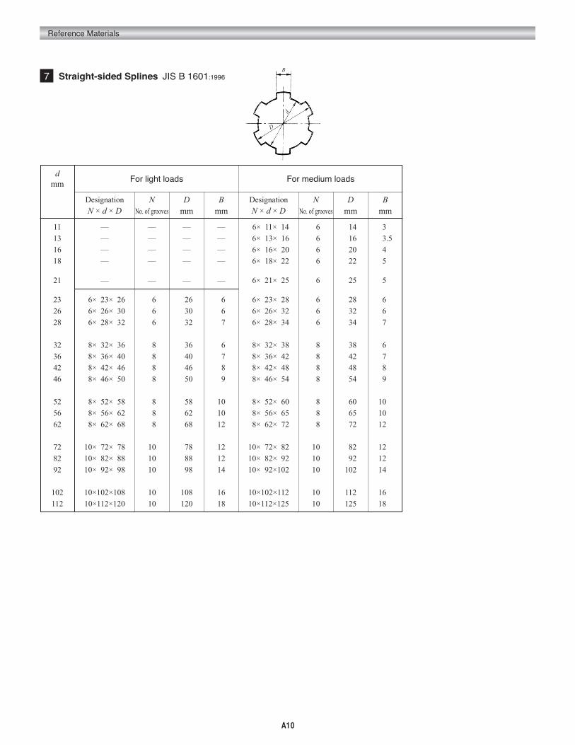
7 Straight-sided Splines JIS B 1601:1996
11
13
16
18
21
23
26
28
32
36
42
46
52
56
62
72
82
92
102
112
For light loads
Designation
N × d × D
—
—
—
—
—
06×023×026
06×026×030
06×028×032
08×032×036
08×036×040
08×042×046
08×046×050
08×052×058
08×056×062
08×062×068
10×072×078
10×082×088
10×092×098
10×102×108
10×112×120
NNo. of grooves
—
—
—
—
—
06
06
06
08
08
08
08
08
08
08
10
10
10
10
10
Dmm
—
—
—
—
—
026
030
032
036
040
046
050
058
062
068
078
088
098
108
120
Bmm
For medium loads
Designation
N × d × D
06×011×014
06×013×016
06×016×020
06×018×022
06×021×025
06×023×028
06×026×032
06×028×034
08×032×038
08×036×042
08×042×048
08×046×054
08×052×060
08×056×065
08×062×072
10×072×082
10×082×092
10×092×102
10×102×112
10×112×125
NNo. of grooves
06
06
06
06
06
06
06
06
08
08
08
08
08
08
08
10
10
10
10
10
Dmm
014
016
020
022
025
028
032
034
038
042
048
054
060
065
072
082
092
102
112
125
Bmm
030.
03.5
040.
050.
050.
060.
060.
070.
060.
070.
080.
090.
100.
100.
120.
120.
120.
140.
160.
180.
dmm
D
B
d

Reference Materials
A11
The design concept of the spline surface strength is the same as that of a key. Here is the formula for the allowable transmission force (N) of spline.
F=ηzhlσwhere η :Contact ratio of surface (0.3~0.9) z :Number of teeth
h :Contact depth of teeth
(In the direction of tooth depth) ( mm )
l :Contact length of spline
(In the direcion of tooth trace) ( mm )
σ :Allowable surface stress of spline ( MPa )
Fixed……………………… 68.6 ~ 122.6 〃 Sliding unloaded…………. 44.1 ~ 88.31〃 Sliding loaded……………. 29.4 or under1〃The formula of allowable torque T (N・m) of spline with respect to the surface strength :
T=
where de : Effective diameter of spline shaft mm
In designing a spline shafts, besides considering the surface strength, the tortional and bending stresses of spline should be taken into account.
Tolerance and Fits
Hole
Shaft
Sliding and
fixing
For
slid
ing
For
fixi
ngWidth B
When hub is not hardened
D9
f9
h8
js7 (1) or
k7 (2)
n7
p6
s6
s6 (1) or
u6 (2)
u6
When hub is hardened
F10
d9
e8
f7
h7
h6
js6
m6 (1) or
k6 (2)
m6
Minor dia.
d
H7
e8
f7
g6
js7
js6
k6
m6
n6
Major dia.D
H11
a11
a11
Reference
Basis for selection of fit
For general applications, where fitting length is approximately twice
the minor dia. or more (long fit).
Where precision fit is not required.
For general applicaions, where fitting length is not less than
approximately twice the minor dia. (short fit).
Where precision fitting is required.
Where precision fit is particularly required.
For general applications.
For precision fit.
For firm fixing.
For applications in which no removing is performed.
NOTES (1) Applicable where the width is 6 mm and under. (2)Applicable where the width is over 6 mm.
8 The Surface Strength of Spline
Fde
2000

A12
Reference Materials
Unit: mm
9 Flat Keys and Keyways JIS B 1301:1996
Nominal size of
keyb × h
002×02
003×03
004×04
005×05
006×06
0(07×07)008×07
010×08
012×08
014×09
0(15×10)016×10
018×11
020×12
022×14
0(24×16)025×14
028×16
032×18
0(35×22)036×20
0(38×24)040×22
0(42×26)045×25
050×28
056×32
063×32
070×36
080×40
090×45
100×50
Dimension of keyb
Basic
dim
ensio
n
002
003
004
005
006
007
008
010
012
014
015
016
018
020
022
024
025
028
032
035
036
038
040
042
045
050
056
063
070
080
090
100
Basic
dim
ensio
n
020.
030.
040.
050.
060.
07.2
07.2
080..
080.
090.
10.2
100.
110.
120.
140.
16.2
140.
160.
180.
22.3
200.
24.3
220.
26.3
250.
280.
320.
320.
360.
400.
450.
500.
Tolerance(h9)
+0000.
-0.025
+0000.
-0.0300
+0000.
-0.036
+0000.
-0.043
+0000.
-0.052
+0000.
-0.062
+0000.
-0.074
+0000.
-0.087
Tolerance
+0000.
-0.025
h09
h11
h10
h11
h10
h11
h10
h11
h10
h11
h10
h11
+0000.
-0.030
-0000. -0.036
+0000.
-0.090 0000.-0.070 0000.-0.090
+0000.
-0.110
-0000. -0.070
+0000.
-0.110
0000.-0.084 0000.-0.130-0000.—0.084 0000.-0.130 0000.-0.084
+0000.
-0.130
+0000.
-0.160
h
c
0.160000
~0.25
0.250000
~0.40
0.400000
~0.60
0.600000
~0.80
1.000000
~1.20
1.600000
~2.00
2.500000
~3.00
l
006~020
006~036
008~045
010~056
014~070
016~080
018~090
022~110
028~140
036~160
040~180
045~180
050~200
056~220
063~250
070~280
070~280
080~320
090~360
100~400
—
—
—
—
—
—
—
—
—
—
—
—
002
003
004
005
006
007
008
010
012
014
015
016
018
020
022
024
025
028
032
035
036
038
040
042
045
050
056
063
070
080
090
100
Tight-fit type
-0.004
-0.031
-0.012
-0.042
-0.015
-0.051
-0.018
-0.061
v0.022
-0.074
-0.026
-0.088
-0.032
-0.106
-0.037
-0.124
Normal type
-0.004
-0.029
+0000.
-0.030
+0000.
-0.036
+0000.
-0.043
+0000.
-0.052
+0000.
-0.062
+0000.
-0.074
+0000.
-0.087
±0.0125
±0.0150
±0.0180
±0.0215
±0.0260
±0.0310
±0.0370
±0.0435
r1
and
r2
0.080000
~0.16
0.160000
~0.25
0.250000
~0.40
0.400000
~0.60
0.700000
~1.000
1.200000
~1.60
2.000000
~2.50
01.2
01.8
02.5
03.0
03.5
04.0
04.0
05.0
05.0
05.5
05.0
06.0
07.0
07.5
09.0
08.0
09.0
10.0
11.0
11.0
12.0
12.0
13.0
13.0
15.0
17.0
20.0
20.0
22.0
25.0
28.0
31.0
01.0
01.4
01.8
02.3
02.8
03.3
03.3
03.3
03.3
03.8
05.3
04.3
04.4
04.9
05.4
08.4
05.4
06.4
07.4
11.4
08.4
12.4
09.4
13.4
10.4
11.4
12.4
12.4
14.4
15.4
17.4
19.5
+0.1
+00.
+0.2
+00.
+0.3
+00.
b1
andb2
b1 b2
Tolerance(P9)
Tolerance(N9)
Tolerance(JS9)
Dimension of keyway Note
Suitableshaft dia. d
006~008
008~010
010~012
012~017
017~022
020~025
022~030
030~038
038~044
044~050
050~055
050~058
058~065
065~075
075~085
080~090
085~095
095~110
110~130
125~140
130~150
140~160
150~170
160~180
170~200
200~230
230~260
260~290
290~330
330~380
380~440
440~500
b2
t 2
d
r2
Keyway of holeKeyway of shaft
d
t1
b1
r1
lb
c
h
Basi
c di
men
son
of b
1 and
b2
Tole
ranc
e o
f t1
and
t2
Basi
c di
men
son
of t
2
Basi
c di
men
son
of t
1

Reference Materials
A13
1.1.00531.01601.04721.05831.06391.09281.14001.14241.1545
1.19681.22761.251.25661.27001.32281.32991.39631.41111.4508
1.47841.51.57081.58751.59591.67551.69331.751.77321.7952
1.81431.93331.95381.99492.2.09442.09992.11672.18552.2166
2.252.28482.30912.34702.39362.49372.52.51332.54002.6456
2.65992.752.79252.82222.8499
02.956803.03.069103.141603.175003.191803.2503.324903.351003.5
03.590403.627103.628603.7503.866603.989804.04.188804.199804.2333
04.433204.504.569604.618204.693904.987305.05.026505.080005.3198
05.505.585105.644405.699806.06.138206.283206.3506.506.6497
07.07.180807.254207.257107.979708.08.377608.399708.466708.8663
09.09.236309.387809.974610.
010.0531010.16010.6395011.011.2889011.3995012.012.2764012.5664012.7000
013.013.2993014.014.5083014.5143015.015.9593016.016.7552016.9333
017.7326018.019.9492020.020.32022.022.7991023.024.025.
025.1327025.4026.026.5989028.029.030.031.4159031.9187032.
033.8663034.036.038.039.8683040.045.050.050.2955050.8
053.1977063.5000079.8019084.6667127.0000
Circular Pitch (C.P.)
10 Comparative Table for Gear Pitch and Module
Diametral Pitch
Diametral Pitch
Diametral Pitch
Circular Pitch (C.P.) Circular Pitch (C.P.)Modulem
Modulem
Modulem
25.400025.265625.24.255024.23.873323.244422.281722.233922.
21.223120.690220.320020.212720.19.201919.098618.191418.17.5071
17.180616.933316.170116.15.915515.159515.14.514314.324014.1489
14.13.138213.12.732412.700012.127612.095812.11.622311.4592
11.288911.117011.10.822510.611710.185910.160010.106310.09.6010
09.549309.236409.095709.08.9127
8.59048.46678.27618.08518.7.95777.81537.63947.57987.2571
7.07447.00237.6.77336.56916.36626.35006.06386.04796.
5.72965.64445.55855.55.41135.09305.08005.05325.4.7747
4.61824.54794.54.45634.23334.13804.04254.3.90773.8197
3.62863.53723.50143.53.18313.17503.03193.02403.2.8648
2.82222.752.70562.54652.5400
2.52662.52.38732.30912.252.22822.11672.06902.02132.
1.95381.90991.81431.75071.751.69331.59151.58751.51601.5
1.43241.41111.27321.27001.251.15451.11411.10431.05831.0160
1.01061.0.97690.95490.90710.87590.84670.80350.79580.7938
0.750.74710.70560.66840.63660.63500.56440.50800.50530.5
0.47750.40.31830.30.2
in in in
3.14163.1⁄83.09223.2.96852.95282.7⁄82.75592.3⁄42.7211
2.5⁄82.55912.51332.1⁄22.47382.3⁄82.36222.1⁄42.22642.1654
2.1⁄82.09442.1.97901.96851.7⁄81.85531.79521.77171.3⁄4
1.73161.5⁄81.60791.57481.57081.1⁄21.49611.48431.7⁄16
1.4173
1.39631.3⁄81.36061.33861.5⁄16
1.25981.25661.1⁄41.23691.3⁄16
1.18111.14241.1⁄81.11321.1024
1.1⁄16
1.04721.02361.0.98950.98430.96660.94490.15⁄16
0.8976
0.7⁄80.86610.86580.83780.13⁄16
0.78740.78540.3⁄40.74800.7421
0.70870.6981011⁄16
0.68030.66950.62990.62830.5⁄80.61840.5906
0.57120.9⁄16
0.55660.55120.52360.51180.1⁄20.49480.48330.4724
0.44880.7⁄16
0.43310.43290.39370.39270.3⁄80.37400.37110.3543
0.34910.34010.33470.31500.3142
.5⁄16
.3092
.2953
.2856
.2783
.2756
.2618
.2559
.1⁄4
.2474
.2417
.2362
.2244
.2165
.2164
.2094
.1969
.1963
.3⁄16
.1855
.1772
.1745
.1575
.1571
.1546
.1428
.1378
.1366
.1309
.1257
.1⁄8
.1237
.1208
.1181
.1122
.1083
.1047
.1⁄10
.0984
.0982
.0928
.0924
.0873
.0827
.0787
.0785
.0698
.0628
.1⁄16
.0618
.0576
.0498
.0394
.0371
.0247
mm mm mm
79.79679.37578.54276.20075.40075.73.02570.69.85069.116
66.67565.63.83763.50062.83560.32560.57.15056.55155.
53.97553.19850.80050.26750.47.62547.12545.59845.44.450
43.98341.27540.84140.39.89838.10038.37.70136.51336.
35.46534.92534.55934.33.33832.31.91931.75031.41730.163
30.29.01728.57528.27528.
26.98826.59926.25.40025.13325.24.55224.23.81322.799
22.22522.21.99121.28020.63820.19.94919.05019.18.849
18.17.73317.46317.28017.16.15.95915.87515.70715.
14.50814.28814.13814.13.29913.12.70012.56812.27612.
11.39911.11311.10.99610.09.97509.52509.509.42609.3
08.86608.63908.508.07.980
7.9387.8547.57.2547.0697.6.6506.56.3506.283
6.1386.5.7005.55.4995.3205.4.9874.7634.712
4.54.4334.3.9903.9273.6273.53.4703.3253.193
3.1753.1423.0693.2.8502.7512.6602.5402.52.494
2.3572.3472.2172.1002.1.9951.7731.5961.5881.570
1.51.2561.0.9420.628

A14
Reference Materials
01.60
020.0
02.50
03.15
040.0
050.0
06.30
080.0
100.0
12.50
160.0
180.0
22.40
280.0
01.60
020.0
02.50
03.15
0400
050.0
6.30
080.0
100.0
12.50
160.0
180.0
22.40
280.0
3 Center Holes JIS B 1011:1987
60° Centre hole
dNominal diameter
D D1D2
(Min.)l NOTE 1
(Max.) l1
Informative note
l2 l3 t a
(0.50)(0.63)(0.80)
100.
(1.25)1.60
200.
2.50
3.15
400.
(5)00.
6.30
(8)00.
100.0
01.06
01.32
01.70
02.12
02.65
03.35
04.25
05.30
06.70
08.50
10.60
13.20
170.0
21.20
010.
01.2
01.5
01.9
02.2
02.8
03.3
04.1
04.9
06.2
07.5
09.2
11.5
14.2
0.2
0.3
0.3
0.4
0.6
0.6
0.8
0.9
10.
1.3
1.6
1.8
20.
2.2
0.48
0.60
0.78
0.97
1.21
1.52
1.95
2.42
3.07
3.90
4.85
5.98
7.79
9.70
00.64
00.80
01.01
01.27
01.60
01.99
02.54
03.20
04.03
05.05
06.41
07.36
09.35
11.66
00.68
00.90
01.08
01.37
01.81
02.12
02.75
03.32
04.07
05.20
06.45
07.78
09.79
11.90
0.5
0.6
0.7
0.9
1.1
1.4
1.8
2.2
2.8
3.5
4.4
5.5
70.
8.7
0.16
0.20
0.23
0.30
0.39
0.47
0.59
0.78
0.96
1.15
1.56
1.38
1.56
1.96
NOTE 1: The value l shall not be less than the value t.NOTE: The nominal diameters in parentheses should not be used whenever possible.
Unit: mm
φ D2
( t)
( l 3)l
b
φ Dφ D1
φ D φ d
60° ,
max
.
60° ,
max
.
120°
φ d
( t)
( l 2)l
(a )
( t)
φ d
( l 1)l
φ D60
° , m
ax.
Type A Type B Type C
b(Approx.)

Reference Materials
A15
Related to runout
Related to orientation
AccuraciesRelated to form
Properties
Straightness
Flatness
Roundness
Cylindricity
Profile of any line
Profile of any surface
Parallelism
Perpendicularity
Angularity
Profile of any line
Profile of any surface
Concentricity
Coaxiality
Symmetry
Profile of any line
Profile of any surface
Runout
Total runout
Symbols
12 Permissible Machining Deviations in Dimensions without Tolerance Indication JIS B 0405:1991
14 Geometrical Characteristic Symbol JIS B 0021:1998
Unit: mm
Grade
Div. of dimensions
From 0.5 up to 3
Over 3 up to 6
Over 6 up to0 30
Over 30 up to 120
Over 120 up to 400
Over 400 up to 1000
Over 1000 up to 2000
Fine Grade
(Grade 12)
± 0.05
± 0.10
± 0.15
± 0.20
± 0.30
± 0.50
Medium Grade
(Grade 14)
± 0.1
± 0.2
± 0.3
± 0.5
± 0.8
± 1.2
Coarse Grade
(Grade 16)
—
± 0.2
± 0.5
± 0.8
± 1.2
± 20.
± 30.
13 Permissible Deviations in Dimensions without Tolerance Indication for Injection Molded Products In-house standard
Div. of dimensions Tolerance
± 0.20
± 0.25
± 0.30
± 0.35
± 0.40
PositionRelated to position From 0.5 up to 3
Over 3 up to 6
Over 6 up to 10
Over 10 up to 18
Over 18 up to 30
Unit: mm

A16
Reference Materials
JIS B 1702-01: 1998 and JIS B1702-02: 1998 cancel and replace the former JIS B 1702: 1976 (Gear accuracy of spur gear and helical gear). This revision was made to adjust to International Standard Organization (ISO) standards.
Shown here are tables, extracted from JIS B 1702-01 and 1702-02, concerning the gear accuracy.
To distinguish new standards from old ones, each of the grades under the new standards has the prefix "N".
Discrepancies between new and old standards As some change in the classification has been made of module and reference diameter (reference pitch diameter, in old standards), there may be some difficulties to find out what old grade in question corresponds to which new grade.As a yardstick new accuracy grades are said to be equal to old accuracy grades plus 4. In certain cases, however, this yardstick does not apply.
As the need arises, please refer to "JGMA/TR 0001 (2000): Comparison table between new and old accuracy grades".
15 Cylindrical Gears: ISO System of Accuracy Part 1 JIS B 1702-01: 1998
Table 1 Single pitch deviation ± fpt
Reference
diameter
dmm
005≦d≦200
020<d≦500
050<d≦125
125<d≦280
280<d≦560
ModuleAccuracy grades
fpt
μm
N4
3.3
3.7
3.5
3.9
4.3
4.9
3.8
4.1
4.6
5.0
6.5
8.0
4.2
4.6
5.0
5.5
6.5
8.0
4.7
5.0
5.5
6.0
7.0
9.0
04.7
05.0
05.0
05.5
06.0
07.0
05.5
06.0
06.5
07.5
09.0
11.0
06.0
06.5
07.0
08.0
09.5
12.0
06.5
07.0
08.0
08.5
10.0
12.0
06.5
07.5
07.0
07.5
08.5
10.0
07.5
08.5
09.0
10.0
13.0
16.0
08.5
09.0
10.0
11.0
13.0
16.0
09.5
10.0
11.0
12.0
14.0
18.0
09.5
10.0
10.0
11.0
12.0
14.0
11.0
12.0
13.0
15.0
18.0
22.0
12.0
13.0
14.0
16.0
19.0
23.0
13.0
14.0
16.0
17.0
20.0
25.0
13.0
15.0
14.0
15.0
17.0
20.0
15.0
17.0
18.0
21.0
25.0
31.0
17.0
18.0
20.0
23.0
27.0
33.0
19.0
20.0
22.0
25.0
29.0
35.0
19.0
21.0
20.0
22.0
24.0
28.0
21.0
23.0
26.0
30.0
35.0
44.0
24.0
26.0
28.0
32.0
38.0
47.0
27.0
29.0
31.0
35.0
41.0
50.0
26.0
29.0
28.0
31.0
34.0
40.0
30.0
33.0
36.0
42.0
50.0
63.0
34.0
36.0
40.0
45.0
53.0
66.0
38.0
41.0
44.0
49.0
58.0
70.0
37.0
41.0
40.0
44.0
48.0
56.0
43.0
47.0
52.0
59.0
71.0
89.0
48.0
51.0
56.0
64.0
75.0
93.0
54.0
57.0
62.0
70.0
81.0
99.0
053.0
059.0
056.0
062.0
068.0
079.0
061.0
066.0
073.0
084.0
100.0
125.0
067.0
073.0
079.0
090.0
107.0
132.0
076.0
081.0
088.0
099.0
115.0
140.0
N5 N6 N7 N8 N9 N10 N11 N12
mmm
0.5≦m≦20.
0.2<m≦3.5
0.5≦m≦20.
0.2<m≦3.5
3.5<m≦60.
06<m≦10.
0.5≦m≦20.
0.2<m≦3.5
3.5<m≦60.
0.6<m≦10.
.10<m≦16.
.16<m≦25.
0.5≦m≦20.
0.2<m≦3.5
3.5<m≦60.
0.6<m≦10.
.10<m≦16.
.16<m≦25.
0.5≦m≦20.
0.2<m≦3.5
3.5<m≦60.
0.6<m≦10.
.10<m≦16..16<m≦25.

Reference Materials
A17
Table 2 Total cumulative pitch deviation Fp
Reference
diameter
dmm
005≦d≦200
020<d≦500
050<d≦125
125<d≦280
280<d≦560
ModuleAccuracy grades
Fp
μm
N4
08.0
08.5
10.0
10.0
11.0
12.0
13.0
13.0
14.0
14.0
15.0
17.0
17.0
18.0
18.0
19.0
20.0
21.0
23.0
23.0
24.0
24.0
25.0
27.0
11.0
12.0
14.0
15.0
15.0
16.0
18.0
19.0
19.0
20.0
22.0
24.0
24.0
25.0
25.0
26.0
28.0
30.0
32.0
33.0
33.0
34.0
36.0
38.0
16.0
17.0
20.0
21.0
22.0
23.0
26.0
27.0
28.0
29.0
31.0
34.0
35.0
35.0
36.0
37.0
39.0
43.0
46.0
46.0
47.0
48.0
50.0
54.0
23.0
23.0
29.0
30.0
31.0
33.0
37.0
38.0
39.0
41.0
44.0
48.0
49.0
50.0
51.0
53.0
56.0
60.0
64.0
65.0
66.0
68.0
71.0
76.0
032.0
033.0
041.0
042.0
044.0
046.0
052.0
053.0
055.0
058.0
062.0
068.0
069.0
070.0
072.0
075.0
079.0
085.0
091.0
092.0
094.0
097.0
101.0
107.0
045.0
047.0
057.0
059.0
062.0
065.0
074.0
076.0
078.0
082.0
088.0
096.0
098.0
100.0
102.0
106.0
112.0
120.0
129.0
131.0
133.0
137.0
143.0
151.0
064.0
066.0
081.0
084.0
087.0
093.0
104.0
107.0
110.0
116.0
124.0
136.0
138.0
141.0
144.0
149.0
158.0
170.0
182.0
185.0
188.0
193.0
202.0
214.0
090.0
094.0
115.0
119.0
123.0
131.0
147.0
151.0
156.0
164.0
175.0
193.0
195.0
199.0
204.0
211.0
223.0
241.0
257.0
261.0
266.0
274.0
285.0
303.0
127.0
133.0
162.0
168.0
174.0
185.0
208.0
214.0
220.0
231.0
248.0
273.0
276.0
282.0
288.0
299.0
316.0
341.0
364.0
370.0
376.0
387.0
404.0
428.0
N5 N6 N7 N8 N9 N10 N11 N12
mmm
0.5≦m≦20.
0.2<m≦3.5
0.5≦m≦20.
0.2<m≦3.5
3.5<m≦60.
06<m≦10.
0.5≦m≦20.
0.2<m≦3.5
3.5<m≦60.
0.6<m≦10.
.10<m≦16.
.16<m≦25.
0.5≦m≦20.
0.2<m≦3.5
3.5<m≦60.
0.6<m≦10.
.10<m≦16.
.16<m≦25.
0.5≦m≦20.
0.2<m≦3.5
3.5<m≦60.
0.6<m≦10.
.10<m≦16.
.16<m≦25.

A18
Reference Materials
Table 3 Total profile deviation Fα
Reference
diameter
dmm
005≦d≦200
020<d≦500
050<d≦125
125<d≦280
280<d≦560
ModuleAccuracy grades
Fα
μm
N4
03.2
04.7
03.6
05.0
06.0
07.5
04.1
05.5
06.5
08.0
10.0
12.0
04.9
06.5
07.5
09.0
11.0
13.0
06.0
07.5
08.5
10.0
12.0
14.0
04.6
06.5
05.0
07.0
09.0
11.0
06.0
08.0
09.5
12.0
14.0
17.0
07.0
09.0
11.0
13.0
15.0
18.0
08.5
10.0
12.0
14.0
16.0
19.0
06.5
09.5
07.5
10.0
12.0
15.0
08.5
11.0
13.0
16.0
20.0
24.0
10.0
13.0
15.0
18.0
21.0
25.0
12.0
15.0
17.0
20.0
23.0
27.0
09.0
13.0
10.0
14.0
18.0
22.0
12.0
16.0
19.0
23.0
28.0
34.0
14.0
18.0
21.0
25.0
30.0
36.0
17.0
21.0
24.0
28.0
33.0
39.0
13.0
19.0
15.0
20.0
25.0
31.0
17.0
22.0
27.0
33.0
40.0
48.0
20.0
25.0
30.0
36.0
43.0
51.0
23.0
29.0
34.0
40.0
47.0
55.0
18.0
26.0
21.0
29.0
35.0
43.0
23.0
31.0
38.0
46.0
56.0
68.0
28.0
36.0
42.0
50.0
60.0
72.0
33.0
41.0
48.0
56.0
66.0
78.0
026.0
037.0
029.0
040.0
050.0
061.0
033.0
044.0
054.0
065.0
079.0
096.0
039.0
050.0
060.0
071.0
085.0
102.0
047.0
058.0
067.0
079.0
093.0
110.0
037.0
053.0
041.0
057.0
070.0
087.0
047.0
063.0
076.0
092.0
112.0
136.0
055.0
071.0
084.0
101.0
121.0
144.0
066.0
082.0
095.0
112.0
132.0
155.0
052.0
075.0
058.0
081.0
099.0
123.0
066.0
089.0
108.0
131.0
159.0
192.0
078.0
101.0
119.0
143.0
171.0
204.0
094.0
116.0
135.0
158.0
186.0
219.0
N5 N6 N7 N8 N9 N10 N11 N12
mmm
0.5≦m≦20.
0.2<m≦3.5
0.5≦m≦20.
0.2<m≦3.5
3.5<m≦60.
06<m≦10.
0.5≦m≦20.
0.2<m≦3.5
3.5<m≦60.
0.6<m≦10.
.10<m≦16.
.16<m≦25.
0.5≦m≦20.
0.2<m≦3.5
3.5<m≦60.
0.6<m≦10.
.10<m≦16.
.16<m≦25.
0.5≦m≦20.
0.2<m≦3.5
3.5<m≦60.
0.6<m≦10.
.10<m≦16.
.16<m≦25.

Reference Materials
A19
280<d≦560
Table 4 Total helix deviation Fb
Reference
diameter
dmm
005≦d≦200
020<d≦500
050<d≦125
125<d≦280
FacewidthAccuracy grades
Fb
μm
N4
04.3
04.9
05.5
06.5
04.5
05.0
05.5
06.5
08.0
04.7
05.5
06.0
07.0
08.5
10.0
12.0
05.0
05.5
06.5
07.5
08.5
10.0
12.0
06.0
06.5
07.5
09.0
11.0
12.0
06.0
07.0
08.0
09.5
06.5
07.0
08.0
09.5
11.0
06.5
07.5
08.5
10.0
12.0
14.0
16.0
07.0
08.0
09.0
10.0
12.0
14.0
17.0
08.5
09.5
11.0
13.0
15.0
17.0
08.5
09.5
11.0
13.0
09.0
10.0
11.0
13.0
16.0
09.5
11.0
12.0
14.0
17.0
20.0
23.0
10.0
11.0
13.0
15.0
17.0
20.0
24.0
12.0
13.0
15.0
18.0
21.0
25.0
12.0
14.0
16.0
19.0
13.0
14.0
16.0
19.0
23.0
13.0
15.0
17.0
20.0
24.0
28.0
33.0
14.0
16.0
18.0
21.0
25.0
29.0
34.0
17.0
19.0
22.0
26.0
30.0
35.0
17.0
19.0
22.0
26.0
18.0
20.0
23.0
27.0
32.0
19.0
21.0
24.0
28.0
33.0
40.0
46.0
20.0
22.0
25.0
29.0
35.0
41.0
47.0
24.0
27.0
31.0
36.0
43.0
49.0
24.0
28.0
31.0
37.0
25.0
29.0
32.0
38.0
46.0
27.0
30.0
34.0
39.0
47.0
56.0
65.0
29.0
32.0
36.0
41.0
49.0
58.0
67.0
34.0
38.0
44.0
52.0
60.0
70.0
35.0
39.0
45.0
52.0
36.0
40.0
46.0
54.0
65.0
38.0
42.0
48.0
56.0
67.0
79.0
92.0
40.0
45.0
50.0
58.0
69.0
82.0
95.0
48.0
54.0
62.0
73.0
85.0
98.0
049.0
055.0
063.0
074.0
051.0
057.0
065.0
076.0
092.0
053.0
060.0
068.0
079.0
094.0
112.0
130.0
057.0
063.0
071.0
082.0
098.0
116.0
134.0
068.0
076.0
087.0
103.0
121.0
139.0
069.0
078.0
089.0
105.0
072.0
081.0
092.0
107.0
130.0
076.0
084.0
095.0
111.0
133.0
158.0
184.0
081.0
090.0
101.0
117.0
139.0
164.0
190.0
097.0
108.0
124.0
146.0
171.0
197.0
N5 N6 N7 N8 N9 N10 N11 N12
bmm
004≦b≦100
010<b≦200
020<b≦400
040<b≦800
004≦b≦100.
010<b≦200.
020<b≦400
040<b≦800
080<b≦160.
004≦b≦100.
010<b≦200
020<b≦400
040<b≦800
080<b≦160
160<b≦250
.250<b≦400
004≦b≦100
010<b≦200
020<b≦400
040<b≦800
080<b≦160
160<b≦250
.250<b≦400
010≦b≦200
020<b≦400
040<b≦800
080<b≦160
160<b≦250
250<b≦400

A20
Reference Materials
125<d≦280
Table 5 Total radial composite deviation Fi'' JIS B 1702-2
Reference diameter
dmm
005≦d≦200
020<d≦500
050<d≦125
280<d≦560
560<d≦1000
Normal moduleAccuracy grades
Fi''μm
N4
07.508.009.0100.110.140.09.0100.110.110.130.160.200.260.120.120.130.140.150.180.220.280.150.160.160.170.190.210.250.320.190.200.210.220.230.260.300.360.250.250.260.270.280.310.350.420.
11121214162013141516182228371617181922253140212223242630364528292930333742513536373840445059
15161819222819202123263139522325262731364457303133343743516439404243465260735051525457627083
021023025027032039026028030032037044056074033035036039043051062080042044046048053061072090055057059061065073084103070072074076080088099118
030033035038045056037040042045052063079104046049052055061072088144060063065068075086102127078081083086092104119145099102104107114125141166
042046050054063079052056060064073089111147066070073077086102124161085089092097106121144180110114117122131146169205140144148152161177199235
060066070076089112074080085091103126157209093098103109122144176227120126131137149172203255156161166172185207239290198204209215228250281333
085093100108126158105113120128146178222295131139146154173204248321170178185193211243287360220228235243262293337410280288295304322353398471
120131141153179223148160169181207251314417185197206218244288351454240252261273299343406509311323332344370414477580396408417429455499562665
N5 N6 N7 N8 N9 N10 N11 N12
mn
mm
0.2≦mn≦00.50.5<mn≦00.80.8<mn≦01.01.0<mn≦01.51.5<mn≦02.52.5<mn≦04.00.2≦mn≦00.50.5<mn≦00.80.8<mn≦01.01.0<mn≦01.51.5<mn≦02.52.5<mn≦04.04.0<mn≦06.06.0<mn≦100.0.2≦mn≦00.50.5<mn≦00.80.8<mn≦01.01.0<mn≦01.51.5<mn≦02.52.5<mn≦04.04.0<mn≦06.06.0<mn≦100.0.2≦mn≦00.50.5<mn≦00.80.8<mn≦01.01.0<mn≦01.51.5<mn≦02.52.5<mn≦04.04.0<mn≦06.06.0<mn≦100.0.2≦mn≦00.50.5<mn≦00.80.8<mn≦01.01.0<mn≦01.51.5<mn≦02.52.5<mn≦04.04.0<mn≦06.06.0<mn≦100.0.2≦mn≦00.50.5<mn≦00.80.8<mn≦01.01.0<mn≦01.51.5<mn≦02.52.5<mn≦04.04.0<mn≦06.06.0<mn≦100.

Reference Materials
A21
Table 6 shows the allowable runout appearing in JIS B 1702-2:1998 Appendix B (Reference material)
Table 6 Runout Fr(μm)
Reference
diameter
005≦d≦200
020<d≦500
050<d≦125
125<d≦280
280<d≦560
Normal module
0.5≦mn≦02.0
2.0<mn≦03.5
0.5≦mn≦02.0
2.0<mn≦03.5
3.5<mn≦06.0
6.0<mn≦100.
0.5≦mn≦02.0
2.0<mn≦03.5
3.5<mn≦06.0
6.0<mn≦100.
1000<mn≦160 0
1600<mn≦250 0
0.5≦mn≦02.0
2.0<mn≦03.5
3.5<mn≦06.0
6.0<mn≦100.
1000<mn≦160 0
1600<mn≦250 0
0.5≦mn≦02.0
2.0<mn≦03.5
3.5<mn≦06.0
6.0<mn≦100.
1000<mn≦160 0
1600<mn≦250 0
Accuracy grades
N4
06.5
06.5
08.0
08.5
08.5
09.5
100.
110.
110.
120.
120.
140.
140.
140.
140.
150.
160.
170.
180.
180.
190.
190.
200.
210.
N5
09.0
09.5
110.
120.
120.
130.
150.
150.
160.
160.
180.
190.
200.
200.
200.
210.
220.
240.
260.
260.
270.
270.
290.
300.
N6
13
13
16
17
17
19
21
21
22
23
25
27
28
28
29
30
32
34
36
37
38
39
40
43
N7
18
19
23
24
25
26
29
30
31
33
35
39
39
40
41
42
45
48
51
52
53
55
57
61
N8
25
27
32
34
35
37
42
43
44
46
50
55
55
56
58
60
63
68
73
74
75
77
81
86
N9
036
038
046
047
049
052
059
061
062
065
070
077
078
080
082
085
089
096
103
105
106
109
114
121
N10
051
053
065
067
070
074
083
086
088
092
099
109
110
113
115
120
126
136
146
148
150
155
161
171
N11
072
075
092
095
099
105
118
121
125
131
140
154
156
159
163
169
179
193
206
209
213
219
228
242
N12
102
106
130
134
139
148
167
171
176
185
198
218
221
225
231
239
252
272
291
296
301
310
323
343
Fr
μmd
mmmn
mm
A22
Reference Materials
Acc
urac
y gr
ades
0
1
2
3
4
5
6
Error
Single pitch error(±)
Total Composite Error (±)
Run Out Error
Single pitch error(±)
Single pitch error(±)
Single pitch error(±)
Single pitch error(±)
Pitch variation
04 04 004 004 005 005 004 004 004 005 005 006 004 004 005 005 006 006
05 05 005 005 006 006 005 005 006 006 007 007 005 006 006 007 008 008
14 15 016 017 018 020 015 016 017 019 020 022 017 018 019 021 023 026
05 07 010 014 020 028 007 010 014 020 028 040 010 014 020 028 040 056
06 07 007 007 008 009 007 007 008 008 009 010 007 008 008 009 010 011
08 09 009 010 010 011 009 009 010 011 011 013 010 010 011 012 013 014
25 26 028 030 032 034 027 029 030 032 035 039 030 032 034 036 040 044
07 10 015 021 030 043 010 015 021 030 043 060 015 021 030 043 060 086
12 12 013 013 014 015 012 013 014 014 016 017 013 014 015 016 017 019
15 16 016 017 018 020 016 017 018 019 020 022 017 018 019 021 023 025
46 48 050 053 057 061 049 052 054 058 062 068 054 056 060 064 069 076
11 15 022 031 045 063 015 022 031 045 063 089 022 031 045 063 089 125
023 023 025 026 028 030 024 025 027 028 031 033
029 030 032 034 036 039 031 033 035 037 040 043
090 094 098 105 110 120 097 100 105 115 120 135
16 24 033 048 067 095 024 033 048 067 095 135 033 048 067 095 135 190
041 042 044 046 049 052 043 045 047 050 055 057
053 055 057 060 063 068 056 058 3061 065 069 075
165 170 175 185 195 210 170 180 190 200 210 230
25 35 050 071 100 145 035 050 071 100 145 200 050 071 100 145 200 290
110 115 120 125 132 150
37 52 075 105 150 210 052 075 105 150 210 300 075 105 150 210 300 430
210 220 240 250 270 290
56 79 110 160 230 320 079 110 160 230 320 450 110 160 230 320 450 640
Over 0.6m to 1m of
Normal Module
3
to
6 in
cl.
Ove
r
6 to
12
incl
.Reference diameter(mm)
Over 1m to 1.6m of
Normal Module
Over 1.6m to 2.5m of
Normal Module
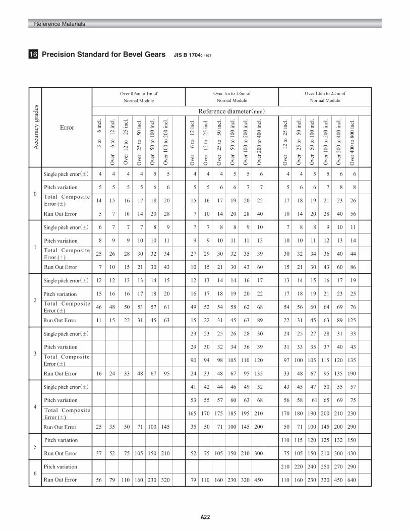
16 Precision Standard for Bevel Gears JIS B 1704: 1978
Run Out Error
Run Out Error
Run Out Error
Run Out Error
Run Out Error
Run Out Error
Pitch variation
Pitch variation
Pitch variation
Pitch variation
Pitch variation
Pitch variation
Total Composite Error (±)
Total Composite Error (±)
Total Composite Error (±)
Total Composite Error (±)
Ove
r
6 to
12
incl
.
Ove
r 12
to
25
incl
.
Ove
r 1
2 to
25
incl
.
Ove
r 100
to 2
00 in
cl.
Ove
r 5
0 to
100
incl
.
Ove
r 2
5 to
50
incl
.
Ove
r 400
to 8
00 in
cl.
Ove
r 200
to 4
00 in
cl.
Ove
r 100
to 2
00 in
cl.
Ove
r 5
0 to
100
incl
.
Ove
r 2
5 to
50
incl
.
Ove
r 1
2 to
25
incl
.
Ove
r 200
to 4
00 in
cl.
Ove
r 100
to 2
00 in
cl.
Ove
r 5
0 to
100
incl
.
Ove
r 2
5 to
50
incl
.

Reference Materials
A23
Over 6m to 10m of
Normal Module
7
Acc
urac
y gr
ades
0
1
2
3
4
5
6
Error
005 005 005 006 006 007 008 005 006 006 007 007 008 006 006 007 007 008 009
006 006 007 007 008 009 010 007 007 008 009 009 011 008 008 009 009 010 011
018 019 021 022 024 027 031 021 022 024 026 029 032 024 025 027 029 032 035
010 014 020 028 040 056 079 014 020 028 040 056 079 014 020 028 040 056 079
008 008 009 010 010 012 013 009 010 010 011 012 014 010 011 011 012 013 015
010 011 012 012 014 015 017 012 012 013 014 016 018 013 014 015 016 017 019
032 033 036 038 042 046 051 036 038 041 045 049 054 041 043 046 049 054 059
015 021 030 043 060 086 120 021 030 043 060 086 120 021 030 043 060 086 120
014 015 016 017 018 020 022 016 017 018 019 021 023 018 019 020 021 023 025
018 019 020 022 024 026 029 021 022 023 025 027 030 023 024 026 027 030 032
057 059 063 067 072 079 088 064 067 072 077 084 092 071 075 079 084 091 100
022 031 045 063 089 125 180 031 045 063 089 125 180 031 045 063 089 125 180
025 027 028 030 032 035 038 028 030 031 034 036 040 031 033 034 037 039 043
033 034 036 039 041 045 049 037 039 041 044 047 052 041 042 045 048 051 056
100 105 110 120 130 140 150 115 120 125 135 145 160 125 130 140 145 155 170
033 048 067 095 135 190 270 048 067 095 135 190 270 048 067 095 135 190 270
045 047 050 052 055 059 065 050 052 054 058 062 068 054 056 059 062 067 072
059 061 065 067 072 077 084 065 067 071 075 081 088 071 073 077 081 087 100
180 185 200 210 220 240 260 200 210 220 230 250 270 220 230 240 250 270 290
050 071 100 145 200 290 400 071 100 145 200 290 400 071 100 145 200 290 400
115 120 125 130 135 155 170 125 130 135 150 165 175 135 140 155 165 175 185
075 105 150 210 300 430 600 105 150 210 300 430 600 105 150 210 300 430 600
220 240 250 260 280 290 310 250 260 270 290 300 330 270 280 290 310 320 340
110 160 230 320 450 640 900 160 230 320 450 640 900 160 230 320 450 640 900
250 360 500 720 1000 1450 2000 360 500 720 1000 1450 2000 360 500 720 1000 1450 2000
Over 2.5m to 4m of
Normal Module
Reference diameter(mm)
Over 4m to 6m of
Normal Module
Single pitch error(±)
Total Composite Error (±)
Run Out Error
Pitch variation
Single pitch error(±)
Total Composite Error (±)
Run Out Error
Pitch variation
Single pitch error(±)
Total Composite Error (±)
Run Out Error
Pitch variation
Single pitch error(±)
Total Composite Error (±)
Run Out Error
Pitch variation
Single pitch error(±)
Total Composite Error (±)
Run Out Error
Pitch variation
Pitch variation
Pitch variation
Run Out Error
Runout
Run Out Error
Ove
r 400
to
800
incl
.
Ove
r 200
to
400
incl
.
Ove
r 100
to
200
incl
.
Ove
r 5
0 to
10
0 in
cl.
Ove
r 2
5 to
5
0 in
cl.
Ove
r 1
2 to
2
5 in
cl.
Ove
r 800
to 1
600
incl
.
Ove
r 400
to
800
incl
.
Ove
r 200
to
400
incl
.
Ove
r 100
to
200
incl
.
Ove
r 5
0 to
10
0 in
cl.
Ove
r 2
5 to
5
0 in
cl.
Ove
r 800
to 1
600
incl
.
Ove
r 400
to
800
incl
.
Ove
r 200
to
400
incl
.
Ove
r 100
to
200
incl
.
Ove
r 5
0 to
10
0 in
cl.
Ove
r 2
5 to
5
0 in
cl.
Ove
r 800
to 1
600
incl
.

A24
Reference Materials
Normal module: 3
Number of teeth: 25 / 50
Helix angle: 35°
Transverse module: = 3.66
Reference diameter of pinion: 91.5
Reference diameter of gear : 183.0
Pinion
Min. value 70μm、Max. value 170μm
Gear
Min. value 80μm、Max. value 200μm
Backlash
Min. value 1 70+080=150μm
Max. value 170+200=370μm
NOTE1
300
17 Backlash Standard for Spur and Helical Gears JIS B 1703: 1976
Tra
nsve
rse
mod
ule
(mm
)
0.5
1
1.5
2
2.5
3
3.5
4
5
6
7
8
10
12
14
16
18
20
22
25
Reference diameter(mm)
Gear accuracy grades(JIS)0
1540 70 50 90 60 110 70 130 90 170 110 200 140 250 180 320
60 100 70 120 80 150 100 180 120 220 150 270 180 330 230 410
80 140 90 160 110 190 130 230 160 280 190 350 240 420
100 180 120 210 140 250 170 300 200 360 240 440 300 540
110 190 120 220 150 260 170 310 210 380 250 450 310 550
130 240 150 280 180 330 220 390 260 470 310 570 380 690
140 250 160 290 190 340 220 400 270 480 320 580 390 700
150 270 170 310 200 360 230 420 280 500 330 590 400 720
160 300 190 340 210 390 250 450 290 530 350 620 420 750
180 330 200 370 230 410 260 480 310 560 360 650 430 780
200 360 220 390 240 440 280 510 320 580 380 680 450 810
210 380 240 420 260 470 300 540 340 610 400 710 460 840
270 480 300 530 330 590 370 670 430 770 500 900
300 540 330 590 360 650 410 730 460 830 530 950
330 600 360 650 390 710 440 790 490 890 560 1010
390 710 420 760 470 850 530 950 590 1070
430 770 460 830 500 910 560 1000 630 1130
460 820 490 890 540 960 590 1060 660 1190
520 950 570 1020 620 1120 690 1250
570 1030 620 1110 670 1210 740 1330
Min. valueMax. value
20
25
25
25
30
30
35
35
40
45
35
40
45
50
50
50
60
60
70
70
80
90
45
50
50
60
60
60
60
70
70
80
90
90
110
120
130
60
60
60
70
70
70
80
80
90
90
100
110
120
130
140
160
170
180
70
70
80
80
80
90
90
90
100
110
110
120
130
140
160
170
180
200
210
230
90
90
100
100
100
110
110
120
120
130
140
150
160
180
190
200
210
230
250
120
120
130
130
130
140
150
150
160
170
180
200
210
220
240
250
270
150
160
160
170
170
180
190
200
210
220
240
250
260
280
5 5 5 5 5 5 5 5 5 5 50 0 0 0 0 0 0 0 0 0
1.5
to
3 incl.
Over 3
to
6 incl.
Over 6
to
12 incl.
Over 12
to
25 incl.
Over 25
to
50 incl.
Over 50
to
100 incl.
Over 100
to
200 incl.
Over 200
to
400 incl.
Over 400
to
800 incl.
Over 800
to
1600 incl.
Over 1600
to
3200 incl.
Backlash Caluculation Chart (JIS Grade 0 and Grade 5) Unit: μm
Calculation of BacklashAccuracy grade JIS 0
Backlash Calculation FormulaJIS0
NOTE112345678
Min. value
10W
Max. value25W.528W.531.5W35.5W40W.545W.550W.563W.590W.5
W: Unit of tolerance
W=3√d0+0.65ms(μm)where d0:Reference diameter (mm) ms:Transverse module (mm)NOTE 1.Use 12.5W as the min. value under high speed rotation.
cos 35°3
Am
out o
f To
oth
Thi
nnin
g
Min. valueMax. valueMin. valueMax. valueMin. valueMax. valueMin. valueMax. valueMin. valueMax. valueMin. valueMax. valueMin. valueMax. valueMin. valueMax. valueMin. valueMax. valueMin. valueMax. valueMin. valueMax. valueMin. valueMax. valueMin. valueMax. valueMin. valueMax. valueMin. valueMax. valueMin. valueMax. valueMin. valueMax. valueMin. valueMax. valueMin. valueMax. value

Reference Materials
A25
Reference diameter(mm)
Am
out o
f To
oth
Thi
nnin
g
18 Backlash Standard for Bevel Gears JIS B 1705: 1973
Tra
nsve
rse
mod
ule
(mm
)
0.5
1
1.5
2
2.5
3
3.5
4
5
6
7
8
10
12
14
16
18
20
22
25
Gear accuracy grades(JIS)0
2050 100 60 120 70 150 90 180 110 230 140 280
7060 140120 80 160 100 200 120 240 150 300
9080 180150 110 220 130 260 160 310 190 380
120100 230200 140 280 170 330 200 400 240 490
120110 250210 150 290 170 350 210 420 250 310500 610
150130110 310270230 180 360 220 430 260 310520 630
160140120 320280240 190 380 220 450 270 320540 640
170150130 340300260 200 400 230 470 280 550 330 660
190160 370330 210 430 250 500 290 580 350 690
200180 410360 230 460 260 530 310 620 360 730
220200 440400 240 490 280 560 320 650 380 760
240210 470430 260 530 300 600 340 680 400 790
300270240 590540490 330 660 370 750 430 860
330300 660600 360 730 410 810 460 920
360330 720670 390 790 440 880 490 990
420390360 850790730 470 940 530 1050
460430 920850 500 1010 560 1120
490460 990920 540 1070 590 1180
570520490 11401050980 620 1250
620570540 123011501070 670 1340
25
2525
30
35
3530
35
40
45
5040
5045
45
50
50
60
60
605045
606050
706050
7070
8070
9080
9090
60
60
60
70
70
70
80
80
90
90
100
110
120110100
130120
140130
80
80
80
90
90
90
100
110
110
120
130
140
160
170160150
180170
200180
100
100 120
100 130
110 130
110
120
120
130
140
150
160
180
190
200
210
230210200
250230210
130
140
150
150
160
170
180
200
210
220
240
250
270
4 4 4 4 4 4 4 4 40 0 0 0 0 0 0 0
3
to
6 incl.
Over 6
to
12 incl.
Over 12
to
25 incl.
Over 25
to
50 incl.
Over 50
to
100 incl.
Over100
to
200 incl.
Over 200
to
400 incl.
Over 400
to
800 incl.
Over 800
to
1600 incl.
Backlash Caluculation Chart (JIS Grade 0 and Grade 4) Unit: μm
Calculation ofBacklash
Accuracy grade JIS 0
Module: 3
Number of teeth: 25 / 50
Reference diameter of pinion: 75mm
Reference diameter of gear: 150mm
Pinion
Min. value 60μm
Max. value 150μm
Gear
Min. value 70μm
Max. value 180μm
Backlash
Min. value 1 60+070=130μm
Max. value 150+180=330μm
Backlash Calculation FormulaJIS0123456
Min. value
10W
Max. value25W.530W.535.5W42.5W50W.560W.571W.5
W: Unit of tolerance
W=3√d0+0.65ms(μm)where d0 :Reference diameter (mm) ms :Transverse module (mm)
Min. valueMax. valueMin. valueMax. valueMin. valueMax. valueMin. valueMax. valueMin. valueMax. valueMin. valueMax. valueMin. valueMax. valueMin. valueMax. valueMin. valueMax. valueMin. valueMax. valueMin. valueMax. valueMin. valueMax. valueMin. valueMax. valueMin. valueMax. valueMin. valueMax. valueMin. valueMax. valueMin. valueMax. valueMin. valueMax. valueMin. valueMax. valueMin. valueMax. value

A26
Reference Materials
19 Tolerance of Center Distance for Spur and Helical Gears JGMA 1101-01 (2000)
Table 1 Tolerance of center distance ± fa Unit: μm
20 Shaft Parallelism of Spur and Helical Gears JGMA 1102-01 (2000)
Gear accuracy grades
06
08
12
16
22
28
30
55
84
010
012
020
026
035
045
062
088
130
016
020
032
040
055
070
098
140
205
026
031
050
065
088
115
155
220
330
065
080
125
160
220
280
390
550
825
N5,N6 N7,N8 N9,N10 N11,N12
Center distance(mm)
Over
0005
0020
0050
0125
0280
0560
1000
1600
2500
or less
0020
0050
0125
0280
0560
1000
1600
2500
4000
NOTE: It is acceptable to apply another accuracy grade to the tolerance of center distance as the need arises.
Shaft a
Measuring Length
Shaft Offset Error
Shaft b
Shaft Parallelism Error
Allowable Range
A
V
H
L
B
C
O
D
fx
f y
S
N3,N4

Reference Materials
A27
0560<d≦1000
280.
Reference diameter
d(mm)
0125<d≦2800
Table 1 Allowable shaft parallelism error with respect to parallelism of axes per facewidth fx'
0005≦d≦2000
0020<d≦5000
0050<d≦1250
0280<d≦5600
1000<d≦1600
1600<d≦2500
Facewidth
b(mm)Accuracy grades
N404.304.905.506.504.505.005.506.508.004.705.506.0.07.008.5100.120.05.005.506.507.508.5100.120.140.06.006.507.509.0110.120.140.06.507.508.509.5110.130.150.08.009.0100.120.130.160.08.509.5110.120.140.160.
06.007.008.009.506.507.008.009.5110.06.507.508.5100.120.140.160.07.008.009.0100.120.140.170.200.08.509.5110.130.150.170.200.09.5100.120.140.160.180.210.110.120.140.170.190.220.120.130.150.180.200.230.
08.509.5110.130.09.0100.110.130.160.09.5110.120.140.170.200.230.100.110.130.150.170.200.240.
120.130.150.180.210.250.290.130.150.170.190.220.260.300.160.180.200.240.270.310.170.190.220.250.280.320.
1214161913141619231315172024283314161821252934401719222630354119212327323642222529333844242731354046
1719222618202327321921242833404620222529354147562427313643495826293339455160313541475462343843505665
2428313725293238462730343947566529323641495867793438445260708237414755637385445058677688485461708092
035039045052036040046054065038042048056067079092040045050058069082095112048054062073085098115053058066077090103120063071082094107124068076087099112130
04905506307405105706507609205306006807909411213005706307108209811613415806807608710312113916307408209310912714516908910011613315217696107123141159183
069078089105072081092107130076084095111133158184081090101117139164190224097108124146171197231105116132154179205239126141164189215249136152174199225259
N5 N6 N7 N8 N9 N10 N11 N12004≦b≦010010<b≦020020<b≦040040<b≦080004≦b≦010010<b≦020020<b≦040040<b≦080080<b≦160004≦b≦010010<b≦020020<b≦040040<b≦080080<b≦160160<b≦250250<b≦400004≦b≦010010<b≦020020<b≦040040<b≦080080<b≦160160<b≦250250<b≦400400<b≦650010<b≦020020<b≦040040<b≦080080<b≦160160<b≦250250<b≦400400<b≦650010<b≦020020<b≦040040<b≦080080<b≦160160<b≦250250<b≦400400<b≦650020<b≦040040<b≦080080<b≦160160<b≦250250<b≦400400<b≦650020<b≦040040<b≦080080<b≦160160<b≦250250<b≦400400<b≦650
Unit: μm

A28
Reference Materials
Reference diameter
d(mm)
1000<d≦1600
0125<d≦2800
Table 2 Allowable shaft offset error with respect to parallelism of axes per facewidth fy'
0005≦d≦2000
0020<d≦5000
0050<d≦1250
0280<d≦5600
0560<d≦1000
1600<d≦2500
Facewidth
b(mm)Accuracy grades
N41.11.21.41.61.11.31.41.72.01.21.31.51.72.12.52.91.31.41.61.82.22.63.03.51.51.71.92.32.73.13.61.61.82.12.42.83.23.72.02.22.62.93.43.94.52.12.42.73.13.54.0
1.51.72.02.31.61.82.02.42.91.71.92.12.52.93.54.11.82.02.22.63.13.64.24.92.12.42.73.23.84.35.02.32.62.93.44.04.55.52.83.13.64.24.75.56.53.03.43.84.45.05.5
2.22.42.83.32.22.52.93.44.12.42.63.03.54.24.96.02.52.83.23.64.35.06.07.03.03.43.94.65.56.07.03.33.64.14.85.56.57.53.94.45.06.06.58.09.04.34.75.56.07.08.0
03.103.403.904.603.203.604.104.805.503.303.704.204.906.007.008.003.604.004.505.006.007.008.0100.04.304.805.506.507.508.5100.04.705.006.007.008.009.0110.05.506.007.008.509.5110.130.06.006.507.509.0100.110.
04.304.905.506.504.505.005.506.508.004.705.506.007.008.5100.120.05.005.506.507.508.5100.120.140.06.006.507.509.0110.120.140.06.507.508.509.5110.130.150.08.009.0100.120.130.160.180.8.509.50110.120.140.160.
06.007.008.009.506.507.008.009.5110.06.507.508.0100.120.140.160.07.008.009.0100.120.140.170.200.08.509.5110.130.150.170.200.09.5100.120.140.160.180.210.110.120.150.170.190.220.260.120.130.150.180.200.230.
08.509.5110.130.09.0100.110.130.160.09.0110.120.140.170.200.230.100.110.130.150.170.200.240.280.120.130.150.180.210.250.290.130.150.170.190.220.260.300.160.180.200.240.270.310.360.170.190.220.250.280.320.
121416191314161923131517202428331416182125293440171922263035411921232732364222252933384451242731354046
171922261820232732192124283340462022252935414756242731364349582629333945516031354147546273343843505665
N5 N6 N7 N8 N9 N10 N11 N12004≦b≦0010010<b≦0020020<b≦0040040<b≦0080004≦b≦0010010<b≦0020020<b≦0040040<b≦0080080<b≦0160004≦b≦0010010<b≦0020020<b≦0040040<b≦0080080<b≦0160160<b≦0250250<b≦0400004≦b≦0010010<b≦0020020<b≦0040040<b≦0080080<b≦0160160<b≦0250250<b≦0400400<b≦0650010<b≦0020020<b≦0040040<b≦0080080<b≦0160160<b≦0250250<b≦0400400<b≦0650010<b≦0020020<b≦0040040<b≦0080080<b≦0160160<b≦0250250<b≦0400400<b≦0650020<b≦0040040<b≦0080080<b≦0160160<b≦0250250<b≦0400400<b≦0650650<b≦1000020<b≦0040040<b≦0080080<b≦0160160<b≦0250250<b≦0400400<b≦0650
Unit: μm