application and validation of unstructured overset cfd ... · pdf [email protected]...
TRANSCRIPT

Application and Validation of Unstructured OversetCFD Technology for Rotorcraft Gearbox Windage
Aerodynamics Simulation
Matthew J. Hill ∗
The Pennsylvania State UniversityUniversity Park, [email protected]
Robert F. Kunz †
The Pennsylvania State UniversityUniversity Park, PA
Ralph W. Noack ‡
The Pennsylvania State UniversityUniversity Park, PA
Lyle N. Long §
The Pennsylvania State UniversityUniversity Park, PA
Philip J. Morris ¶
The Pennsylvania State UniversityUniversity Park, [email protected]
Robert F. Handschuh‖
NASA Glenn Research CenterCleveland, OH
An unstructured overset moving mesh CFD method is adapted, validated and applied to spinning gearsystems with emphasis on predicting windage losses. Several spur gears and a disc, spinning in air at rotationrates up to 1200 s−1 are studied. It is observed that the CFD simulations return good agreement with measuredwindage power loss, as determined by the deceleration of the gears due to torques exerted by viscous and pressureforces on the gear surfaces. Turbulence modeling choices, the relative importance of viscous and pressure torqueswith gear speed, and the physics of the complex 3D unsteady flow field in the vicinity of the gear teeth are studied.The capabilities and challenges associated with the overset mesh approach for enclosed gear train applicationsare demonstrated.
Introduction
Gearbox windage refers to the power losses associatedwith rotational deceleration torques exerted on spinninggears by aerodynamic forces (pressure and viscous) withinthe air-oil atmosphere present within a gearbox. Windagelosses are a source of significant heating and fuel consump-tion in rotorcraft and other VTOL systems. The weight andpackaging constraints inherent in these systems require thegearing components to be lightweight and heavily loaded.The components are also required to operate at high ro-tational speeds where windage losses become significantwith respect to other gearbox losses (rolling, sliding, andlubrication losses.) Windage losses are relevant to aircraftdesign for several reasons: 1) They can consume severalpercent of the transmitted power. This has significant im-plications for onboard oil cooling requirements and lube
∗Ph.D. Candidate, Department of Aerospace Engineering†Senior Research Associate, Applied Research Laboratory‡Research Associate, Applied Research Laboratory§Professor of Aerospace Engineering¶Boeing/A.D. Welliver Professor of Aerospace Engineering‖Aerospace Engineer, Army Research Laboratory Vehicle Technology
DirectoratePresented at the American Helicopter Society 64th Annual Forum, Montreal,
Canada, April 29 - May 1, 2008. Copyright c© 2008 by the American HelicopterSociety International, Inc. All rights reserved.
system capacity thereby compromising range and standbymilitary readiness for rotorcraft and carrier-based aircraft.2) Rotorcraft platform survivability under transmission oil-out conditions is exacerbated by windage losses which aremanifested as added dissipative flow heating to these al-ready critically thermally stressed systems.
Despite this significant relevance, design effortsthroughout the gearing industry aimed at reducing windagelosses have generally fallen into the trial and error category.Nevertheless, it has been shown by Winfree1 and othersthat modest geometric modifications to control the air flowpath, such as shrouding and baffle configurations, can verysignificantly reduce both windage losses and lubricatingoil consumption (80% and 40% reductions observed, re-spectively, in Ref. 1). However, these hardware specificapproaches are empirical, expensive, and time consuming,and to be relevant need to be performed late in the designcycle.
A host of experimental studies have appeared in the lit-erature.1–8 These studies employ either closed loop sys-tems2–6 or treat isolated gears1, 7, 8 where windage (andother) losses are determined by measuring spin-down ve-locities once the gear+shaft assembly is disconnected fromthe drive torque. Figure 1 shows a diagram of the highspeed helical gear train test facility at the NASA GlennResearch Center. It is a closed-loop system that has been

setup to study the thermal behavior of aerospace-qualitygear components under various speeds, loads, and lubri-cant flow rates.5 Generally, these studies parametrize geargeometry elements, rotational speed, enclosure geometry,and lubrication system characteristics (flow rate, jet loca-tion, lubricant rheology), and use dimensional analysis todevelop correlations for the power losses. These correla-tions, although useful in the design process, are inherentlylimited by the large number of system variables and theattendant limited range of their applicability. Of particularconcern here is the paucity of data/correlations available forhigh speed gears of interest. Indeed, compressibility effectsare mostly not even considered in the literature, althoughhigh speed gears can have tip Mach numbers reaching 0.75.
Fig. 1 NASA High-Speed Helical Gear Train Facility.5
Unfortunately, the physics of these systems are so com-plex that to date there have been no attempts made to em-ploy many modern elements of 3-D computational fluiddynamics (CFD) in analyzing gearbox windage. Recent2-D studies9 were performed using the commercial CFDsolver FLUENT, where a side correlation factor was usedto to account for 3D effects (although these authors statethat work is under way to extend their simulations to 3-D10)Specifically, the fluid mechanics involve complex separatedair flow, disperse multiphase flow (oil droplets) and contin-uous multiphase films (lubricating oil on gears), movingboundaries in contact, and all modes of heat transfer. Ac-cordingly, for a CFD tool to resolve all of the relevantphysics of this problem it must:
• support moving meshes (either adaptive/deforming oroverset) necessary to resolve the gears in relative mo-tion and contact at the gear face
• contain non-equilibrium multiphase flow capability(separate continuity and momentum equations foreach phase; slip between phases) to accommodate thedisperse mist/droplet and continuous film flows
• support suitable turbulence modeling to accommo-date the complex high speed separated flow within thegearbox, and to accurately represent the cascade of en-ergy through turbulence scales into viscous heating
• posses suitable preconditioned time-stepping algorith-mics to efficiently accommodate Mach numbers rang-ing from near zero through high subsonic
• support conduction (gears themselves meshed inter-nally - solve conduction problem in these elements),convection and (for near-failure conditions) radiationmodeling
• be parallelized to run efficiently on modern High Per-formance Computing (HPC) systems.
The overall goal of this research is to adapt, validate andapply a CFD tool that supports these basic gear windagemodeling requirements. This paper represents the first pub-lication of the authors’ efforts in this area, and focuseson the single phase aspect of the problem, although, theCFD code used supports the multiphase flow requirementsthat will be needed in the future. The paper is organizedas follows: First, the governing equations and numericalprocedures, including overset grid technology are reported.Second, several verification cases are reported, where re-sults are compared to analytical solutions for rotating Cou-ette flow, flow near an infinite spinning disc, and thermalCouette flow. Next several validation cases are reported,including windage loss predictions compared to data ob-tained by Diab et al.,8 for a spinning disk and four spurgears. Gridding requirements and turbulence modeling arediscussed.
Theoretical FormulationGoverning Equations
The conservation of mass, momentum and energy can bewritten in integral conservation law form for a compress-ible flow through a moving mesh as:
∂
∂t
∫∀
ρd∀+∫S
ρ(V −W ) ·dS = 0 (1)
∂
∂t
∫∀
ρV d∀+∫S
ρV (V −W ) ·dS =−∫S
pdS +∫S
τ ·dS
(2)
∂
∂t
∫∀
ρEd∀+∫S
ρH (V −W ) ·dS =∫S
(τ ·V
)·dS+Wf +qH
(3)In equations 1-3, V is the velocity vector, and W is the
velocity of the surface element, dS, both in the absoluteframe of reference. In the present work, all verification andvalidation flows studied are either incompressible, or havemaximum local absolute Mach numbers of less than 0.35.Accordingly, for all simulations presented in this paper,an incompressible assumption is invoked and the energyequation is not solved (except for the thermal Couette flowsimulation where it is solved subject to a constant densityconstraint).

A high-Reynolds number k-ε turbulence model and asublayer resolved hybrid k-ε/k-ω turbulence model due toMenter11 are used in the studies that follow. No explicittransition model was employed as justified, for now, by thesmall contribution of near-axis viscous torques on windageloss.
CFD Numerics and Code
The CFD code used in this work, NPHASE-PSU12
is a parallel face-based, cell-centered, arbitrary-elementunstructured multiphase flow solver which has been in-strumented with overset mesh capability. The baselinealgorithm follows established segregated pressure basedmethodology. A collocated variable arrangement is usedand a lagged coefficient linearization is applied.13 Di-agonal dominance preserving, finite volume spatial dis-cretization schemes are used for the scalar transport equa-tions. Continuity is introduced through a pressure cor-rection equation, based on the SIMPLE-C algorithm.14
In constructing cell face fluxes, a momentum interpola-tion scheme15 is employed which introduces damping inthe continuity equation. Grid motion/deformation termsare implemented in a Geometric-Conservation-Law (GCL)preserving fashion.16 A dual-time formulation is employedwhere at each physical timestep, between 5 and 20 pseudo-timesteps of the SIMPLE-C algorithm are applied. Specif-ically, at each pseudo-timestep, the discrete momentumequations are solved approximately (using a simple pointiterative scheme), followed by a more exact solution of thepressure correction equation (using the PETSC17 parallelLU preconditioning+GMRES utilities). Turbulence scalarand energy equations are then solved in succession. Paral-lelization is implemented in a standard fashion by invokingdomain decomposition based on METIS18 in the front end,and MPI based message passing in the CFD code. Allof the large scale simulations presented in this paper wereexecuted on the Columbia supercomputer at NASA AmesResearch Center. The code scales very well on this systemas illustrated in Figure 2.
Fig. 2 Parallel efficiency of NPHASE-PSU on Columbia sys-tem for a 1.1x10⁶ cell spinning cylinder case.
DiRTlib and SUGGAR
The overset grid approach19 utilizes a composite gridconsisting of a set of overlapping component grids todiscretize the domain. No point-to-point or face-to-facematching is required between component grids. The so-lution on the component grids are linked by identifyingappropriate intergrid boundary points (IGBPs) where thesolution is given by a specified boundary value obtainedby interpolation from another overlapping donor compo-nent grid. The overset domain connectivity information(DCI), which consists of the identification of the intergridboundary points and corresponding interpolation sources,is obtained by an overset grid assembly step. The currenteffort utilizes two overset software libraries to add the over-set capability to NPHASE-PSU.
DiRTlib,20 which stands for Donor interpolation Recep-tor Transaction library, is a solver neutral library that en-capsulates the functionality required by the solver to utilizethe overset domain connectivity information. It is inde-pendent of the solver grid storage and topology, dependentvariables, etc. and can be used with any solver. The solvercalls a few functions to initialize the library, load the DCIinterpolation, and transfer the data to appropriate proces-sors in a parallel execution environment, and apply the in-terpolated data as boundary values at IGBPs. Solver func-tions must be provided and are called by DiRTlib to get andput data in the correct solver dependent variable storagelocations. When the solver executes in a distributed mem-ory parallel computational environment the solver mustalso inform DiRTlib of the parallel decomposition enablingDiRTlib to get/put data from the appropriate parallel pro-cess.
The current overset grid assembly process is performedusing the SUGGAR code,21 which stands for Structured,Unstructured, Generalized overset Grid AssembleR. SUG-GAR is a general overset grid assembly code with the ca-pability to create the domain connectivity information atnode and/or element centers for most current grid topolo-gies including any combination of structured Cartesian andcurvilinear, unstructured tetrahedral and mixed element,general polyhedral, and octree based Cartesian grids. Forstatic grid assemblies with no motion between componentgrids the grid assembly is a pre-processing step. The caseof solution and time dependent motion, requires the solverto communicate the new body and grid positions to the gridassembly process, wait for it to complete, and then load thenew DCI. For the case of prescribed motion, such as usedin the present study, the DCI is a-priori computed and savedin a file for each time step in the simulation and the solversimply loads the file appropriate for each time step.
The donor interpolations produced by SUGGAR area set of linear weights that multiply the values at thedonor members. For a cell centered flow solver, such asNPHASE-PSU, the interpolation stencil will use as mem-bers the cell in the donor grid that was found to contain anIGBP and the neighboring cells that share a face with thedonor cell. The interpolation weights are computed using

an unweighted least square procedure.
Results
Verification StudiesIn the context of the overset meshing strategy employed
for gearbox windage simulations, the meshes will be inmotion relative to one another. As indicated above, the ap-proach taken here is to solve the flow in the absolute frameof reference for the entire computational domain, i.e. onall meshes, those that are rotating and those that are sta-tionary. In order to verify that NPHASE-PSU correctlyhandles these gear relevant rotating mesh systems, two ver-ification studies were performed, rotating Couette flow, andflow near an infinite rotating disc, both of which have avail-able analytical solutions.
Rotating Coutte FlowFigure 3 is an illustration of the 33x81 (radial x az-
imuthal) computational domain for the incompressible ro-tating Couette flow case. The inner and outer boundariesare walls. In this case, rinner = 0.5 and router = 1.0. Theouter cylinder is held stationary and a rotation rate ofω = 1s−1 is specified for the inner cylinder. The Reynoldsnumber independent analytical solutions for the tangentialvelocity and pressure are:
Vθ = Cr(
1− 1r2
)(4)
p = ρ
(C2r2
2−2C2ln(r)− C2
2r2
)(5)
C = −ω
3(6)
Figure 4 shows a comparison of the analytical solution withthree NPHASE-PSU runs, designated Approaches 1, 2, and3. Approach 1 solves the absolute velocities in the ab-solute frame on a stationary grid (adapting inner cylinderboundary conditions accordingly). Approach 2 solves forthe relative velocities in the relative frame on a stationarygrid (i.e. frame of reference rotating with angular velocity,ω, adapting the momentum equation source terms and outercylinder boundary conditions accordingly). Approach 3solves for absolute velocities in the absolute frame usinga time accurate analysis on a rotating mesh. Approach 3 isthe most relevant for gear analysis. Figure 4 illustrates thatthe code returns the analytical solution for all three simula-tion approaches to within the accuracy of the second orderaccurate discretization numerics and grid used.
Flow Near an Infinite Rotating DiscThe second verification case is a classic 3-D exact solu-
tion to the incompressible Navier-Stokes (N-S) equations.An infinite radial span disk rotates with an angular velocity,ω. This induces tangential flow in the direction of rotation,radial outflow, and an axial flow towards the center of thedisc. In this case, the N-S equations reduce to a system of
Fig. 3 Computational domain for the rotating Coutte flowcase.
Fig. 4 Comparison of NPHASE-PSU and analytical solutionsfor the rotating Couette flow case.
non-linear ODEs which can essentially be exactly solvednumerically. Figure 5 is notional sketch of the flow fieldfrom Schlichting.22
Figure 6 shows the 232662 element unstructured meshemployed for the analysis. The extent of the computationaldomain was selected to be rmax = 1.0, zmax = 1.0. For achoice of ω = 1.0 and µ = 1.0x10⁻², this domain providedthat the solution sampled within the region r≤ 0.2, z≤ 0.4compares very closely with the exact solution despite thenecessarily finite extent of the domain.
NPHASE-PSU was applied using two approaches. Ap-proach 1 solves the absolute velocities in the absolute frameon a stationary grid (adapting disk boundary conditions ac-cordingly). Approach 2 solves for absolute velocities inthe absolute frame using a time accurate analysis on a ro-tating mesh. Figure 7 illustrates that the code returns theexact solution for both simulations to within the accuracy

Fig. 5 Sketch of the flow field in the vicinity of an infinite spanrotating disc.
Fig. 6 232662 element unstructured mesh employed for theinfinite spanning rotating disc.
of the second order accurate discretization numerics andgrid used.
Couette Flow with Wall HeatingThe third validation performed sought to verify the
viscous dissipation term implementation in NPHASE-PSU. The relevance of viscous dissipation physics to gearwindage is significant as discussed above. The analyticalsolution for the temperature distribution in a laminar linearCouette flow was chosen. Figure 8 shows a diagram of theconfiguration. The product of the Prandtl number (Pr ≡µCp/k) and the Eckert number (Ec ≡ U2
1 /Cp(T1 − T0)),PrEc, is a measure of the role of viscous dissipation ina flow. The nearly exact comparisons between CFD re-sult and the analytical solution, shown in Figure 9, across arange of PrEc, illustrates that the viscous dissipation termsin NPHASE-PSU are implemented correctly.
Validation Studies
The experimental data of Diab et al.8 was used to val-idate NPHASE-PSU for the case of unshrouded, isolated,rotating spur gears. Diab et al.8 tested four different spurgears and a disk in free air on a spin-down test rig. Thegears varied in diameter, width, and tooth count. The prop-
Fig. 7 Comparison of NPHASE-PSU and exact solutions forthe infinite span rotating disc.
Fig. 8 Illustration of the linear heated Couette flow case.
Fig. 9 Comparison of NPHASE-PSU and exact solutions forthe linear heated Couette flow case.
erties of the gears and disk used by Diab et al.8 are providedin Table 1. Diab et al.8 did not study the effects of gear en-closure or lubrication. A sequence of prescribed constantrotation rate simulations was used to replicate the experi-ment.

Table 1 Diab et al.8 Gear Properties.
Pitch Diameter Tooth Width Module(mm) (mm) (mm)
Gear 1 288 30 4Gear 2 144 30 4Gear 3 144 60 4Gear 4 144 60 6Disk 300 30
Single Grid Simulations
Grids were generated for all four spur gears and the disk.For the gear studies where the high Reynolds number k-ε turbulence model was used, near-wall grid spacing wasdefined to accommodate wall-functions (e.g., y+ ' 70 forgear 1, ω= 1000 s−1). The single plane of symmetry in theproblem was exploited to reduce total cell count by a factorof 2. Grid cell counts for the different cases varied between2x106 (Gear 4) and 8x10⁶ (Gear 1). Grid generation wasfurther simplified by employing a hybrid mesh topology, asillustrated in Figure 10. Specifically, for the regions abovethe surface of the gear teeth to the outer boundary, struc-tured hexahedral cells were used. For the region above thegear face surface, unstructured prism cells were employed.The meshes were generated using the commercial grid gen-eration software package Gridgen.23 The computationaldomain of the isolated gear grids was extended to approx-imately five times the gear radius from the gear surface inall directions. It was found that this distance was adequatefor defining a symmetry boundary condition since the flowis nearly stagnant there.
An azimuthal step size of 1/40th of one tooth passageduration (the time it takes one tooth to rotate to the positionof the tooth adjacent to it) was used in all CFD calculations.This corresponds to 2880 timesteps per gear revolution forGear 1, 1440 timesteps for Gears 2 & 3, and 960 timestepsfor Gear 4. All cases used 10 pseudo-time iterations perphysical timestep.
CFD runs were made for four gears and the disk at a
Fig. 10 Grid topology of Gear 4.
number rotation speeds. All cases were run for at least 2complete revolutions to remove simulation startup transientbehavior. Convergence histories show that transients leavethe solution after about one revolution as illustrated in Fig-ure 11, where it is also observed that pseudo-time residualdrop approximately 2 orders of magnitude in each physicaltimestep when 10 pseudo-timesteps are used per physicaltimestep.
Fig. 11 Example convergence history for Diab Gear 4.
Comparisons between the power loss results of Diabet al.8 and the NPHASE-PSU analysis are presented inFig. 12 for all four gears. The CFD analysis for all 4 gearsexhibited very good agreement with experiment. The diskcase, however, did not share this same level of agreement,as illustrated in Figure 13, where NPHASE-PSU resultsare seen to underpredict the measured power loss. In or-der to elucidate the reasons for the deterioration in solutionaccuracy observed for the disk case, a number of observa-tions and studies were made. First, it is observed that themeasured (and computed) windage loss power levels forthe disk are much smaller than the comparably sized spur

gear (Gear 1, D ' 300 mm). This arises due to the ab-sence of any azimuthal pressure variation in the disc flow -torque losses are due entirely to viscous effects, and theseare clearly underpredicted. Indeed the absolute magnitudesof loss underprediction between the disk and Gear 1 arecomparable (e.g. ' 50W @ 600s−1), so presumably thisunderprediction of shear is present in all of the gear simu-lations, however its relative magnitude is small.
To explore this further, the low-Reynolds number Mentermodel was applied to the spinning disc case (using an ap-propriate sublayer resolved mesh). Figure 13 illustratesthat improved turbulence modeling does benefit solutionaccuracy especially at higher rotation rates. This observa-tion is not as important for the gear cases since the spin-down torques associated with azimutally varying pressureforces in the vicinity of the gear teeth dominate the viscousforces as shown in Figures 14 and 15. It can be seen that,especially at lower rotation rates, the contribution of vis-cous loss to total windage loss, is small. However, we doobserve that at higher pitchline velocities the relative mag-nitude of the viscous torque increases with respect to thepressure torque. This can be see for higher rotation rateson Gear 1 (Figure 14) as well as by considering the smallersize (and hence lower pitchline velocities) of Gear 2 (Fig-ure 15).
In summary our results suggest that for the very highspeed gears to be encountered in rotorcraft (and other highperformance aircraft) transmissions, viscous effects willbecome more important than encountered here, and willtherefore require attendant research attention.
Fig. 12 Comparisons between the experimental results andthe NPHASE-PSU analysis.
Details of 3-D Flow FieldA number of important physical features of the predicted
flow field are available upon interrogation of the CFD simu-lations. Figure 16 shows a view of the predicted secondaryvelocity vectors on the symmetry plane in the gear relativeframe of reference for one of the Diab cases. One can see
Fig. 13 Effect of turbulence model selection on viscous workprediction.
Fig. 14 Breakdown of windage power losses for Diab 1.
a significant vortical structure within the gear tooth region,and the tooth-to-tooth periodicity that has been achievedin the transient simulation. Figure 17 shows a view of thepredicted surface pressure distributions for the four Diabgears. There, comparatively large vs. small pressures areobserved on the leading and trailing tooth faces - this dif-ference being the source of the pressure component of thespin-down torque. The highly three-dimensional nature ofthe flow in these relatively low aspect ratio spurs gears arealso clearly seen (figure shows only 1/2 of each gear). Sig-nificant 3-D effects are also clearly visualized in Figure 18where gear relative streamlines are displayed in the neartooth region along with an isosurface of predicted staticpressure in a region of high pressure.

Fig. 15 Breakdown of windage power losses for Diab 2.
Fig. 16 Predicted velocity vectors in the symmetry plane of aDiab gear.
Fig. 17 Predicted surface pressure distributions for the fourDiab gears.
Overset Grid SimulationsAs of the writing of this paper, the overset capabil-
ity for spinning gear simulations has been established inNPHASE-PSU. In this context, we are pursuing an oversetverification effort and a relevant validation effort. The veri-fication effort involves solving isolated spinning gear casesstudied above using a rotating near-gear mesh and a station-ary farfield mesh, the necessary approach to be used in on-going gearbox windage activities. Figure 19 shows a viewof an overset Diab Gear 4 simulation. Surface pressure
Fig. 18 Predicted relative frame streamlines and isosurfaceof a high pressure region for Diab Gear 4.
contours are displayed along with overset gear and back-ground meshes on the symmetry plane. As expected, theCFD code returns nearly identical results for this movinggrid overset simulation to the non-overset results reportedabove. We continue to parameterize gridding requirementsin the overlap region, including the proximity of the over-lap region to the gear in assessing the retained accuracy ofthe overset approach.
Fig. 19 Verification study: 3-D overset grid solution andtopology for Diab Gear 4.
The validation effort under way involves simulating a se-ries of shrouded low speed gears for which windage lossmeasurements were made by Dawson.7 To date we havedeveloped valid overset assembly grid topologies for this,as shown in Figure 20, and anticipate reporting CFD anal-ysis for these configurations in the near future.
ConclusionThis paper has summarized the adaptation and validation
status of a CFD method for gear windage aerodynamics.Validation studies of 3-D spur gears in free space demon-strate very good agreement with published data. The fol-lowing conclusions apply: 1) Viscous/turbulence modelingwas identified as a shortcoming since loss power was con-sistently underpredicted for the viscous-drag-only spinningdisk cases. 2) Low Reynolds number (sublayer resolved)
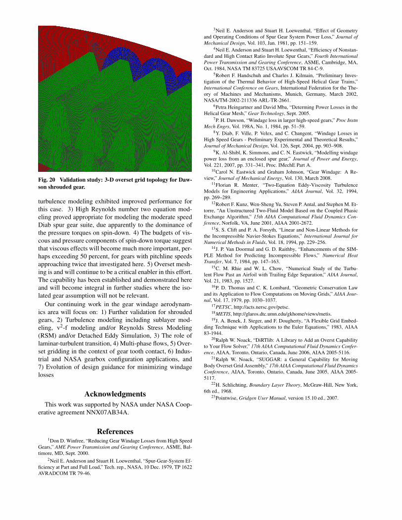
Fig. 20 Validation study: 3-D overset grid topology for Daw-son shrouded gear.
turbulence modeling exhibited improved performance forthis case. 3) High Reynolds number two equation mod-eling proved appropriate for modeling the moderate speedDiab spur gear suite, due apparently to the dominance ofthe pressure torques on spin-down. 4) The budgets of vis-cous and pressure components of spin-down torque suggestthat viscous effects will become much more important, per-haps exceeding 50 percent, for gears with pitchline speedsapproaching twice that investigated here. 5) Overset mesh-ing is and will continue to be a critical enabler in this effort.The capability has been established and demonstrated hereand will become integral in further studies where the iso-lated gear assumption will not be relevant.
Our continuing work in the gear windage aerodynam-ics area will focus on: 1) Further validation for shroudedgears, 2) Turbulence modeling including sublayer mod-eling, v2-f modeling and/or Reynolds Stress Modeling(RSM) and/or Detached Eddy Simulation, 3) The role oflaminar-turbulent transition, 4) Multi-phase flows, 5) Over-set gridding in the context of gear tooth contact, 6) Indus-trial and NASA gearbox configuration applications, and7) Evolution of design guidance for minimizing windagelosses
AcknowledgmentsThis work was supported by NASA under NASA Coop-
erative agreement NNX07AB34A.
References1Don D. Winfree, “Reducing Gear Windage Losses from High Speed
Gears,” AME Power Transmission and Gearing Conference, ASME, Bal-timore, MD, Sept. 2000.
2Neil E. Anderson and Stuart H. Loewenthal, “Spur-Gear-System Ef-ficiency at Part and Full Load,” Tech. rep., NASA, 10 Dec. 1979, TP 1622AVRADCOM TR 79-46.
3Neil E. Anderson and Stuart H. Loewenthal, “Effect of Geometryand Operating Conditions of Spur Gear System Power Loss,” Journal ofMechanical Design, Vol. 103, Jan. 1981, pp. 151–159.
4Neil E. Anderson and Stuart H. Loewenthal, “Efficiency of Nonstan-dard and High Contact Ratio Involute Spur Gears,” Fourth InternationalPower Transmission and Gearing Conference, ASME, Cambridge, MA,Oct. 1984, NASA TM 83725 USAAVSCOM TR 84-C-9.
5Robert F. Handschuh and Charles J. Kilmain, “Preliminary Inves-tigation of the Thermal Behavior of High-Speed Helical Gear Trains,”International Conference on Gears, International Federation for the The-ory of Machines and Mechanisms, Munich, Germany, March 2002,NASA/TM-2002-211336 ARL-TR-2661.
6Petra Heingartner and David Mba, “Determing Power Losses in theHelical Gear Mesh,” Gear Technology, Sept. 2005.
7P. H. Dawson, “Windage loss in larger high-speed gears,” Proc InstnMech Engrs, Vol. 198A, No. 1, 1984, pp. 51–59.
8Y. Diab, F. Ville, P. Velex, and C. Changent, “Windage Losses inHigh Speed Gears - Preliminary Experimental and Theoretical Results,”Journal of Mechanical Design, Vol. 126, Sept. 2004, pp. 903–908.
9K. Al-Shibl, K. Simmons, and C. N. Eastwick, “Modelling windagepower loss from an enclosed spur gear,” Journal of Power and Energy,Vol. 221, 2007, pp. 331–341, Proc. IMechE Part A.
10Carol N. Eastwick and Graham Johnson, “Gear Windage: A Re-view,” Journal of Mechanical Energy, Vol. 130, March 2008.
11Florian R. Menter, “Two-Equation Eddy-Viscosity TurbulenceModels for Engineering Applications,” AIAA Journal, Vol. 32, 1994,pp. 269–289.
12Robert F. Kunz, Wen-Sheng Yu, Steven P. Antal, and Stephen M. Et-torre, “An Unstructured Two-Fluid Model Based on the Coupled PhasicExchange Algorithm,” 15th AIAA Computational Fluid Dynamics Con-ference, Norfolk, VA, June 2001, AIAA 2001-2672.
13S. S. Clift and P. A. Forsyth, “Linear and Non-Linear Methods forthe Incompressible Navier-Stokes Equations,” International Journal forNumerical Methods in Fluids, Vol. 18, 1994, pp. 229–256.
14J. P. Van Doormal and G. D. Raithby, “Enhancements of the SIM-PLE Method for Predicting Incompressible Flows,” Numerical HeatTransfer, Vol. 7, 1984, pp. 147–163.
15C. M. Rhie and W. L. Chow, “Numerical Study of the Turbu-lent Flow Past an Airfoil with Trailing Edge Separation,” AIAA Journal,Vol. 21, 1983, pp. 1527.
16P. D. Thomas and C. K. Lombard, “Geometric Conservation Lawand its Application to Flow Computations on Moving Grids,” AIAA Jour-nal, Vol. 17, 1979, pp. 1030–1037.
17PETSC, http://acts.nersc.gov/petsc.18METIS, http://glaros.dtc.umn.edu/gkhome/views/metis.19J. A. Benek, J. Steger, and F. Dougherty, “A Flexible Grid Embed-
ding Technique with Applications to the Euler Equations,” 1983, AIAA83-1944.
20Ralph W. Noack, “DiRTlib: A Library to Add an Overst Capabilityto Your Flow Solver,” 17th AIAA Computational Fluid Dynamics Confer-ence, AIAA, Toronto, Ontario, Canada, June 2006, AIAA 2005-5116.
21Ralph W. Noack, “SUGGAR: a General Capability for MovingBody Overset Grid Assembly,” 17th AIAA Computational Fluid DynamicsConference, AIAA, Toronto, Ontario, Canada, June 2005, AIAA 2005-5117.
22H. Schlichting, Boundary Layer Theory, McGraw-Hill, New York,6th ed., 1968.
23Pointwise, Gridgen User Manual, version 15.10 ed., 2007.