application construction and finishesmultimedia.3m.com/mws/media/876351o/3mtm-flex-ligh… · ·...
TRANSCRIPT

3
ApplicationFLEX by 3M (the “Product”) is a modular lighting system for dry, interior use (the “Application”). The Product allows easy creation of long, 3D lighting
paths along the interior ceilings or walls of your building. White LED light sources and 3M Air Guide technology provide excellent light uniformity and
efficiency.
Construction and FinishesLight modules are available in matte black, matte white and silver with black or white 10 ft. (3m) power cords. Custom finishes are available upon
request. The light modules are construction with an aluminum enclosure with screen printed front acrylic lens and a 3M proprietary diffuser and
reflector.
Figure 1. Specifications. See Table A, “Part # FLX” for corresponding parts.
X4
S4
X2
S2
Z2I
Z2E
Table A. Specifications
Description Part #FLX
Minimum Lumens* DC Power(W)
AC Power(W)
Weight (lbs / kg)3000 K 4000 K
Straight 2 ft. (0.6m) S2 960 1100 22 31 6.3 / 2.8
Straight 4 ft. (1.2m) S4 1800 2100 43 51 12 / 5.4
X Plane 45° 4 ft. (1.2m) Outer Radius X4 1000 1100 22 30 8.3 / 3.7
X Plane 90° 2 ft. (0.6m) Outer Radius X2 920 1000 25 31 7.0 / 3.2
Z Plane 45° 2 ft. (0.6m) Radius (Interior Lit) Z2I 560 640 14 17 5.0 / 2.2
Z Plane 45° 2 ft. (0.6m) Radius (Exterior Lit) Z2E 560 640 14 17 5.0 / 2.2
FLEX by 3MLight Module System
Specifications

Page 2
Physical DimensionsFigure 2. Straight Modules.
Straight 4 ft. (S4) Straight 2 ft. (S2)
48.0
0
24.0
1.7213.75 13.75
Figure 3. X Plane 45° 4 ft. Outer Radius (X4). X Plane 90° 2 ft. Outer Radius (X2).
45
(13.75) 0
10.25
24.00
24.24
33.92
0
10.25
24.00
34.25
48.00
24.24 1.72
(13.75)
Figure 4. Z Plane 45° 2 ft. Radius (Interior or Exterior Lit, Z2E and Z2I).
45
0
24.00
0
16.91
1.72 13.75
FLEX by 3MLight Module System

Page 3
Light OutputThe light output of individual light modules is carefully controlled to achieve uniform surface brightness for different shapes and sizes. Light is emitted in
a Lambertian pattern from the entire diffuser surface. Planar light modules that are mounted horizontally will have the approximate far field candela
distribution shown in Figure 3. Minimum lumen output performance characteristics are in Table A. Photometric IES files for each module are available
at www.3MArchitecturalMarkets.com
3M uses LEDs that have been tested in accordance with IES LM80 Standards. Projected average LED life is greater than 36,300 hours at 70% of lamp
lumen output (L70). LED lifetime is reported according the IES TM21 standard.
ElectricalThe Product is ETL listed for dry locations. The light modules are preassembled for easy installation. The remotely located 24 V, 96 W, Class 2 LED,
universal input power supplies are field replaceable by a qualified electrician. One power supply is required for each 60–90 W of load (2 to 4 FLEX light
modules depending on size). Power supplies must be mounted in a suitable contractor supplied electrical enclosure. Multiple light modules may be
interconnected such that only one power cord drop is required approximately every 8 linear ft. (2.4m). Contact 3M if you require assistance in
determining the number of power supply kits required for your installation. Refer to Table C for wire requirements if the power supply is located greater
than 10 ft. (3m) from the luminaire.
Table B. Power Supply Specifications
Input Voltage 90 – 277 V AC Single Phase
Dimming 0 – 10 V
Dimensions 12.3” x 2.4” x 1.5”
(312mm x 61mm x 28mm)
Weight 1.8 lbs (0.82kg)
Table C. Maximum Power Supply Remote Distance with 10 ft.(3m) Power Cord
Remote Distance American Wire Gauge (AWG)
25 ft. (7.6m) 18
40 ft. (12.2m) 16
70 ft. (21.3m) 14
110 ft. (33.5m) 12
Figure 5. Typical Candela Distribution. Horizontal Mounting of aPlanar Light Module.
FLEX by 3MLight Module System

Page 4
Mounting OptionsFLEX light modules may be pendant hung horizontally or vertically using aircraft cable and cable grippers (see Figures 6 to 9). FLEX light modules may
also be wall mounted or ceiling mounted (Tgrid suspended ceiling, concrete or gypsum board types). Contact 3M for assistance in determining the
appropriate mounting accessories for your application. A termination plate is required for module ends that are not connected to another module. See
Table D, Accessories, on pages 5 and 6 for descriptions.
Figure 6. Pendant Mounting to a T-grid Type Ceiling, Exploded View
Figure 7. Horizontal Pendant Mount System for Concrete orGypsum Board Ceiling
FLEX by 3M Light Module System

Page 5
Figure 8. Ceiling Surface Mount T-Grid Kit
Front view
Oblique view
Exploded view
Used Between Two FLEX Light Modules
Figure 9. Vertical Pendant and Wall Mount Options. It is also possible to transition from a horizontal pendant
to a wall mount
Table D. Accessories
Accessory Description Items Included
Power Supply Kit 96 W universal input LED power supply. One
power supply is required per 60-90 W of DC
load.
LP1090-23-GG-299-DV and thermal pad
material.
Dimensions 12.3" x 2.4" x 1.5"
Weight: 1.82 lbs
Power Cord Kit Power cords and canopy components. At least
one Power Cord Kit is required per Power
Supply. Power cords are not plenum rated.
10 ft. (3m) power cord (not shown)
Strain relief grommets (Qty: 2)
5 in. (12.7cm) white canopy plate with
0.5 in. (12.7mm) power feed hole
FLEX by 3MLight Module System

Page 6
Table D. Accessories, continued
Accessory Description Items Included
Horizontal Pendant Mount Kit Horizontal intermodule connection plate
assembly and suspension hardware for pendant
attach to a Tgrid suspended ceiling, concrete
or gypsum board.
Horizontal suspension plate assembly
5 in. (12.7cm) white canopy plate
Supported Tbar clip
Cable grippers with ¼-20 thread (Qty. 2)
10 ft. (3m) of 3/64” stainless steel, ball
terminated aircraft cable (Qty: 2)
Canopy bar
Canopy nut
Connection Plate Assembly Connection Plate assembly is used between two
Z2I, two Z2E modules, or in a Z2I to Z2E
transition. May also be used between two S2
modules.
Connection plate assembly
Vertical Pendant Mount Kit
Vertical inter-module connection plate assembly
and suspension hardware for pendant
attachment to a T-grid suspended ceiling,
concrete or gypsum board.
Vertical suspension plate assembly
Supported T-bar clip
Cable gripper
10 ft. (3m) of 3/64” stainless steel
aircraft cable
5 in. (12.7 cm) canopy plate with 0.5"
(12.7mm) power feed hole
5 in. (12.7cm) canopy plate
Ceiling Surface Mount T-Grid Kit Brackets to attach to a Tgrid ceiling when the
light modules must be less than 6 in. (15cm)
from the ceiling.
Tgrid interconnection brackets (Qty: 2)
Threaded studs (Qty: 2)
Latch nuts (Qty: 4)
Wall Mount Bracket Assembly Wall mount bracket assembly for attaching light
modules to a wall. Use with #6 or #8 screws
and suitable wall anchors.
Wall mount bracket assembly
Termination Plate Finished cosmetic termination plate for exposed
module ends not connected to another Light
module.
Termination plate (select finish to match
light modules)
FLEX by 3MLight Module System
Page 7
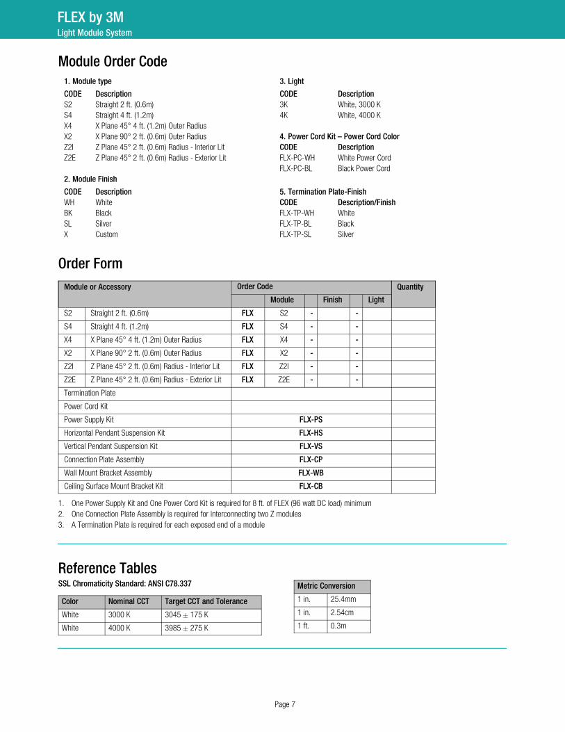
Module Order Code1. Module type 3. Light
CODE Description CODE DescriptionS2 Straight 2 ft. (0.6m) 3K White, 3000 K
S4 Straight 4 ft. (1.2m) 4K White, 4000 K
X4 X Plane 45° 4 ft. (1.2m) Outer Radius
X2 X Plane 90° 2 ft. (0.6m) Outer Radius 4. Power Cord Kit – Power Cord ColorZ2I Z Plane 45° 2 ft. (0.6m) Radius Interior Lit CODE DescriptionZ2E Z Plane 45° 2 ft. (0.6m) Radius Exterior Lit FLXPCWH White Power Cord
FLXPCBL Black Power Cord
2. Module Finish
CODE Description 5. Termination Plate-FinishWH White CODE Description/FinishBK Black FLXTPWH White
SL Silver FLXTPBL Black
X Custom FLXTPSL Silver
Order FormModule or Accessory Order Code Quantity
Module Finish Light
S2 Straight 2 ft. (0.6m) FLX S2 - -
S4 Straight 4 ft. (1.2m) FLX S4 - -
X4 X Plane 45° 4 ft. (1.2m) Outer Radius FLX X4 - -
X2 X Plane 90° 2 ft. (0.6m) Outer Radius FLX X2 - -
Z2I Z Plane 45° 2 ft. (0.6m) Radius Interior Lit FLX Z2I - -
Z2E Z Plane 45° 2 ft. (0.6m) Radius Exterior Lit FLX Z2E - -
Termination Plate
Power Cord Kit
Power Supply Kit FLX-PS
Horizontal Pendant Suspension Kit FLX-HS
Vertical Pendant Suspension Kit FLX-VS
Connection Plate Assembly FLX-CP
Wall Mount Bracket Assembly FLX-WB
Ceiling Surface Mount Bracket Kit FLX-CB
1. One Power Supply Kit and One Power Cord Kit is required for 8 ft. of FLEX (96 watt DC load) minimum
2. One Connection Plate Assembly is required for interconnecting two Z modules
3. A Termination Plate is required for each exposed end of a module
Reference TablesSSL Chromaticity Standard: ANSI C78.337
Color Nominal CCT Target CCT and Tolerance
White 3000 K 3045 � 175 K
White 4000 K 3985 � 275 K
Metric Conversion
1 in. 25.4mm
1 in. 2.54cm
1 ft. 0.3m
FLEX by 3MLight Module System

Part number: 98-0406-0033-4, Revsion B, October 2014 3
WARRANTY DOCUMENTProductFLEX by 3M (the “Product”) is a modular lighting system for dry, interior use (the “Application”).
Limited Warranty
1.When used in the Application, 3M warrants to the party who purchased the Product directly from 3M (the “Buyer”) that the Product will be free from
defects in material and workmanship (the "3M Warranty") for the applicable time period stated below ("Warranty Period"), which will begin on the
earlier of: (a) Product installation date; or (b) three months after 3M's Product shipment date:
1.1 For all but a Product’s power supply component, the Warranty Period is five years.
1.2 For a Product’s power supply component, the Warranty Period is three years.
2.For Buyer’s convenience, 3M may provide a Specification Sheet, other engineering or technical information, recommendations, installation
instructions, and other Productrelated information or materials (all collectively referred to as “Product Information”), but 3M does not warrant any
Product Information.
3.The 3M Warranty is contingent on the Product being stored, wired, installed, maintained, and used only as 3M recommends in all Product Information
and in this Warranty Document. Also, 3M has no obligation under the 3M Warranty as to Product that has been: (a) modified or altered in any manner;
(b) damaged through contact with a person or thing, misuse, accident, vandalism, neglect, or other action by anyone other than 3M; (c) affected by
environmental conditions, such as power fluctuations, improper power supply, or activity by animals or insects; or (d) used not in compliance with all
applicable standards and electrical codes.
4.EXCEPT TO THE EXTENT PROHIBITED BY APPLICABLE LAW, THE 3M WARRANTY IS MADE IN LIEU OF ALL OTHER WARRANTIES, RIGHTS OR
CONDITIONS, EXPRESS OR IMPLIED, STATUTORY OR OTHERWISE, INCLUDING, BUT NOT LIMITED TO, ANY IMPLIED WARRANTY OF
MERCHANTABILITY, SATISFACTORY QUALITY, FITNESS FOR A PARTICULAR PURPOSE AND THOSE ARISING FROM A COURSE OF DEALING, CUSTOM
OR USAGE OF TRADE. BUYER IS RESPONSIBLE FOR DETERMINING IF A PRODUCT IS SUITABLE FOR ITS PARTICULAR PURPOSE AND ITS
INSTALLATION.
Limited Remedy3M must receive any 3M Warranty claim in writing by the earlier of: (a) applicable Warranty Period’s expiration date; or (b) fourteen business days after
Buyer’s discovery of that 3M Warranty claim. If the Product is proven not to have met the 3M Warranty during the applicable Warranty Period, then
BUYER’S EXCLUSIVE REMEDY AND 3M’S SOLE OBLIGATION, WILL BE AT 3M’S OPTION, TO REPAIR OR REPLACE THAT PRODUCT QUANTITY OR
REFUND THE APPLICABLE PURCHASE PRICE.
Limitation of Liability3M WILL NOT UNDER ANY CIRCUMSTANCES BE LIABLE TO BUYER FOR DIRECT (other than the Limited Remedy above), SPECIAL, INCIDENTAL,
INDIRECT OR CONSEQUENTIAL DAMAGES (INCLUDING, WITHOUT LIMITATION, LOSS OF PROFITS) IN ANY WAY RELATED TO A PRODUCT, THIS
WARRANTY DOCUMENT, OR PRODUCT INFORMATION, REGARDLESS OF THE LEGAL OR EQUITABLE THEORY ON WHICH SUCH DAMAGES ARE
SOUGHT.
3M Architectural Markets3M U.S.3M CenterBuilding 22012E04St. Paul, MN 551441000
18886503497 3M.com/AMD
3M Canada1840 Oxford St ELondon, ON N5V 3R618002651840
3M is a trademark of 3M Company. Used under license in Canada. ©3M 2013. All rights reserved. Please recycle.
FLEX by 3MLight Module System