application description 05/2014 s7-based telecontrol via ... · pdf fileapplication...
TRANSCRIPT
Abbildung 0-
http://support.automation.siemens.com/WW/view/en/87447188
Application Description 05/2014
S7-based Telecontrol via DNP3 Protocol CP 1243-1DNP3, TIM 3V-IE DNP3

Warranty and Liability
DNP3 Telecontrol Entry ID: 87447188, V1.0, 05/2014 2
S
iem
ens
AG 2
014
All r
ight
s re
serv
ed
Warranty and Liability
Note The Application Examples are not binding and do not claim to be complete with regard to configuration, equipment or any contingencies. The Application Examples do not represent customer-specific solutions; they are only intended to provide support for typical applications. You are responsible for ensuring that the described products are used correctly. These Application _Examples do not relieve you of the responsibility of safely and professionally using, installing, operating and servicing equipment. When using these Application Examples, you recognize that we cannot be made liable for any damage/claims beyond the liability clause described. We reserve the right to make changes to these Application Examples at any time and without prior notice. If there are any deviations between the recommendations provided in this Application Example and other Siemens publications – e.g. catalogs – the contents of the other documents have priority.
We do not accept any liability for the information contained in this document. Any claims against us – based on whatever legal reason – resulting from the use of the examples, information, programs, engineering and performance data etc., described in this Application Example shall be excluded. Such an exclusion shall not apply in the case of mandatory liability, e.g. under the German Product Liability Act (“Produkthaftungsgesetz”), in case of intent, gross negligence, or injury of life, body or health, guarantee for the quality of a product, fraudulent concealment of a deficiency or breach of fundamental contractual obligations (“wesentliche Vertragspflichten”). The compensation for damages due to a breach of a fundamental contractual obligation is, however, limited to the foreseeable damage, typical for the type of contract, except in the event of intent or gross negligence or injury to life, body or health. The above provisions do not imply a change in the burden of proof to your disadvantage. Any form of duplication or distribution of these Application Examples or excerpts hereof is prohibited without the expressed consent of Siemens Industry Sector.
Security informa-
tion
Siemens provides products and solutions with industrial security functions that support the secure operation of plants, solutions, machines, equipment and/or networks. They are important components in a holistic industrial security concept. With this in mind, Siemens’ products and solutions undergo continuous development. Siemens recommends strongly that you regularly check for product updates.
For the secure operation of Siemens products and solutions, it is necessary to take suitable preventive action (e.g. cell protection concept) and integrate each component into a holistic, state-of-the-art industrial security concept. Third-party products that may be in use should also be considered. For more information about industrial security, visit http://www.siemens.com/industrialsecurity.
To stay informed about product updates as they occur, sign up for a product-specific newsletter. For more information, visit http://support.automation.siemens.com.

Table of Contents
DNP3 Telecontrol Entry ID: 87447188, V1.0, 05/2014 3
S
iem
ens
AG 2
014
All r
ight
s re
serv
ed
Table of Contents Warranty and Liability ................................................................................................. 2
Preface .......................................................................................................................... 5 1 Task ..................................................................................................................... 6
1.1 Overview............................................................................................... 6 1.2 Description of the automation task ....................................................... 6
2 Solution............................................................................................................... 7
2.1 Overview............................................................................................... 7 2.2 Hardware and software components ................................................. 11 2.2.1 Validity ................................................................................................ 11 2.2.2 Components used .............................................................................. 11
3 Basics on DNP3 ............................................................................................... 13
3.1 DNP3 addresses ................................................................................ 13 3.2 DNP3 objects and SINAUT TD7 objects ............................................ 14 3.3 DNP3 classes ..................................................................................... 15 3.3.1 Static data (class 0) ............................................................................ 15 3.3.2 Events................................................................................................. 15 3.4 Index ................................................................................................... 16 3.5 Group and variation ............................................................................ 17 3.6 Implementation level .......................................................................... 17 3.7 Assignment of terms ........................................................................... 17
4 Program Overview ........................................................................................... 19
4.1 STEP 7 V5 project (S7-300) ............................................................... 19 4.2 STEP 7 V12 project (S7-1200) ........................................................... 20 4.3 WinCC project (DNP3 master) ........................................................... 21 4.4 Overview of the data objects .............................................................. 21 4.5 IP addresses in the example .............................................................. 22
5 DNP3 Configuration for S7-300 ...................................................................... 23
5.1 Configuration with the SIMATIC Manager .......................................... 23 5.1.1 Hardware and network configuration ................................................. 23 5.1.2 Time synchronization ......................................................................... 25 5.2 Configuration with the SINAUT ST7 configuration tool ...................... 26 5.2.1 Connection configuration.................................................................... 26 5.2.2 Subscriber administration ................................................................... 27 5.2.3 Configuring the SINAUT TD7 objects ................................................ 28
6 DNP3 Configuration for S7-1200 .................................................................... 31
6.1 Device configuration ........................................................................... 31 6.2 Data point configuration ..................................................................... 35 6.3 E-mail configuration ............................................................................ 39
7 DNP3 Configuration for DNP3 Master ........................................................... 42
7.1 Inserting the DNP3 driver ................................................................... 42 7.2 Settings for the master ....................................................................... 42 7.3 Settings for the connection node TIM / CP ........................................ 43 7.4 Settings for the CPU ........................................................................... 44 7.5 Tag configuration ................................................................................ 48
8 VPN Tunnel Configuration .............................................................................. 51
8.1 Configuration with the SCT tool ......................................................... 52 8.1.1 Creating project and modules ............................................................ 52
Table of Contents
DNP3 Telecontrol Entry ID: 87447188, V1.0, 05/2014 4
S
iem
ens
AG 2
014
All r
ight
s re
serv
ed
8.1.2 Configuring the VPN tunnel ................................................................ 54 8.1.3 Loading the configuration ................................................................... 55 8.2 Configuration with the SCALANCE M874-3 WBM ............................. 56 8.2.1 Insert SIM card and log on to WBM ................................................... 56 8.2.2 Setting the access for the mobile radio network ................................ 57 8.2.3 Configuring the IP address ................................................................. 59 8.2.4 Set system time .................................................................................. 59 8.2.5 VPN tunnel configuration.................................................................... 60 8.2.6 Configuring the SCALANCE M874-3 for the S7-1200 station............ 66
9 Installation ........................................................................................................ 67
9.1 Installation of the hardware ................................................................ 67 9.2 Installation of the software.................................................................. 68 9.3 Installation of the application software ............................................... 68
10 Commissioning ................................................................................................ 69
10.1 Loading the stations ........................................................................... 69 10.1.1 Loading the S7-300 station ................................................................ 69 10.1.2 Loading the S7-1200 station .............................................................. 70 10.2 Configuration for the communication via VPN tunnel ........................ 71 10.2.1 Configuring the e-mail address (S7-1200) ......................................... 71 10.2.2 Adjusting the IP address .................................................................... 72 10.2.3 VPN tunnel configuration.................................................................... 76
11 Operation of the Application .......................................................................... 78
11.1 Overview............................................................................................. 78 11.2 Operating the “Pipeline (S7-300)” station ........................................... 79 11.3 Operating the “Oil Tanks (S7-1200)” station ...................................... 80
12 Diagnostics ...................................................................................................... 82
12.1 Wireshark ........................................................................................... 82 12.2 SINAUT Diagnostics and Service tool ................................................ 83 12.3 TIA Portal ........................................................................................... 87 12.4 SMTP server diagnostics (e-mail) ...................................................... 90
13 Related Literature ............................................................................................ 91
14 History............................................................................................................... 91
Preface
DNP3 Telecontrol Entry ID: 87447188, V1.0, 05/2014 5
S
iem
ens
AG 2
014
All r
ight
s re
serv
ed
Preface The documentation of this application is divided into the following main parts.
Section Chapter
Application Description & Basics
1 Task 2 Solution 3 Basics on DNP3 4 Program Overview
Introduction into the application example and the DNP3 protocol
Configuration Description
5 DNP3 Configuration for S7-300 6 DNP3 Configuration for S7-1200 7 DNP3 Configuration for DNP3 Master 8 VPN Tunnel Configuration
Description of the configurations which have led to the supplied program
Commissioning & Control
9 Installation 10 Commissioning 11 Operation of the Application
Instructions on how to commission the supplied program.
Appendix 12 Diagnostics 13 Related Literature 14 History
Additional information

1 Task 1.1 Overview
DNP3 Telecontrol Entry ID: 87447188, V1.0, 05/2014 6
S
iem
ens
AG 2
014
All r
ight
s re
serv
ed
1 Task 1.1 Overview
Overview of the automation task The outstations “Pipeline” and “Oil Tanks” must be controlled and monitored from a central control station. The figure below provides an overview of the automation task. Figure 1-1
Control Station
Pipeline Oil Tanks
Direction of communication
1.2 Description of the automation task
Requirements of the automation task
• The control station must be capable of requesting process data from the outstations.
• The control station must be able to send commands and setpoint values unsolicited to the outstations.
• The outstations must be able to send process data to the control station unsolicited.
• In the case of a cancelled connection, process data must be saved in the outstations and be sent to the master after the connection has been established again.
• For the implementation, a standardized protocol must be used.

2 Solution 2.1 Overview
DNP3 Telecontrol Entry ID: 87447188, V1.0, 05/2014 7
S
iem
ens
AG 2
014
All r
ight
s re
serv
ed
2 Solution 2.1 Overview
The control station uses telecontrol protocol DNP3 to communicate with the outstation via Ethernet. In the application example, the following types of message frames were configured. • Commands (binary command) • Measured values (analog input event) • Binary messages (binary input event) • Setpoint values (analog output event) Static data (class 0) as well as events of all DNP3 event classes (class 1, 2 and 3) were configured in order to illustrate the properties and differences of the classes. This application shows a complete configuration of a DNP3 system with SIMATIC components. The two following solutions were offered for the hardware configuration.
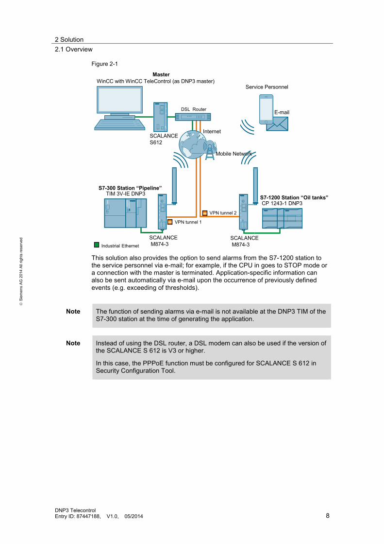
“Configuration via internet/VPN” diagram At the control station, the WinCC TeleControl software is installed, which makes the control station the DNP3 master. An S7-300 CPU with TIM3V-IE DNP3 as DNP3 station is installed on outstation “Pipeline”. Outstation “Oil tanks” consist of an S7-1200 CPU and a CP 1243-1 DNP3. (The CP is responsible for the communication with the control station.) A Virtual Private Network (VPN) is configured for the master to communicate with the stations via the internet. In this example, a DSL connection is available at the master. In addition, a SCALANCE S612 VPN module is installed. In each of the outstations, a SCALANCE M874-3 UMTS and VPN router (incl. SIM card and antenna) is used, which establishes the VPN tunnel to the SCALANCE S612 in the control station. This enables a secure communication via the internet / mobile radio network. The figure below gives a schematic overview of the most important components of the solution:
2 Solution 2.1 Overview
DNP3 Telecontrol Entry ID: 87447188, V1.0, 05/2014 8
S
iem
ens
AG 2
014
All r
ight
s re
serv
ed
Figure 2-1
VPN tunnel 2
VPN tunnel 1
SCALANCEM874-3
SCALANCEM874-3Industrial Ethernet
Master
S7-300 Station “Pipeline”
S7-1200 Station “Oil tanks”
WinCC with WinCC TeleControl (as DNP3 master)
CP 1243-1 DNP3
TIM 3V-IE DNP3
Mobile Network
SCALANCE S612
DSL Router
Internet
Service Personnel
This solution also provides the option to send alarms from the S7-1200 station to the service personnel via e-mail; for example, if the CPU in goes to STOP mode or a connection with the master is terminated. Application-specific information can also be sent automatically via e-mail upon the occurrence of previously defined events (e.g. exceeding of thresholds).
Note The function of sending alarms via e-mail is not available at the DNP3 TIM of the S7-300 station at the time of generating the application.
Note Instead of using the DSL router, a DSL modem can also be used if the version of the SCALANCE S 612 is V3 or higher.
In this case, the PPPoE function must be configured for SCALANCE S 612 in Security Configuration Tool.

2 Solution 2.1 Overview
DNP3 Telecontrol Entry ID: 87447188, V1.0, 05/2014 9
S
iem
ens
AG 2
014
All r
ight
s re
serv
ed
“Configuration via LAN” diagram As an alternative for the solution via internet/VPN, the solution via a switch is offered. In this case, the master and the stations are connected via a local network (LAN). The figure below gives a schematic overview of the most important components of the solution: Figure 2-2
Industrial Ethernet
Master
S7-300 Station “Pipeline”S7-1200 Station “Oil tanks”
WinCC with WinCC TeleControl (as DNP3 master)
CP 1243-1 DNP3TIM 3V-IE DNP3
SCALANCE X
Advantages The solution presented here offers you the following advantages: • Using the standardized DNP3 protocol • Efficient and secure monitoring and control of process engineering plants • Homogenous SIMATIC solution since the SIMATIC Portfolio offers software
and hardware for DNP3 master and outstations. • Connection to all standardized DNP3 master systems • Flexible expansion to up to 65519 outstations

2 Solution 2.1 Overview
DNP3 Telecontrol Entry ID: 87447188, V1.0, 05/2014 10
S
iem
ens
AG 2
014
All r
ight
s re
serv
ed
Scenario The application example is operated via WinCC Runtime. The user interface is displayed in the figure below. Figure 2-3
In station “Pipeline (S7-300)”, pressure and flow rate are measured and sent to the master as unsolicited message frames. At the master, the operator can enter a setpoint for the flow rate. In station “Oil Tanks (S7-1200)”, temperature and filling level are measured. The filling level is sent to the master as unsolicited message frame. If the tank is filled up to 80%, a message is sent to the master with the information that the tank is full. At the same time, the message (alarm) is sent to the service personnel via an e-mail. At the master, the operator has the option to open the valve so the tank is not overfilled. A command is sent to the station via the Valve icon. The measured values of the temperature are saved in the station and only sent after the master has been polled. The old values are sent along and displayed in WinCC Runtime as a trend.
Delimitation This application does not contain any description of the basics of SIMATIC WinCC V7: Basic knowledge of this topic is required.
Assumed knowledge Basic knowledge of configuration & programming with STEP 7 V5 and STEP 7 V12 is assumed.

2 Solution 2.2 Hardware and software components
DNP3 Telecontrol Entry ID: 87447188, V1.0, 05/2014 11
S
iem
ens
AG 2
014
All r
ight
s re
serv
ed
2.2 Hardware and software components
2.2.1 Validity
This application is valid for: • STEP 7 V5.5 SP3 • SINAUT ST7 Engineering V5.3 • S7-300 CPUs (restrictions see link \3\) • STEP 7 V12 SP1 or higher • S7-1200 CPU as of firmware version 3.0 • WinCC V7.0 SP3 Upd 3 • WinCC Telecontrol V7.0 SP3
2.2.2 Components used
The application was set up with the following components:
Hardware components Table 2-1
Component No. Article number Note
FieldPG 1 6ES7716-.....-0... PC requirements in system manual!
CPU 315-2 PN/DP 1 6ES7315-2EH14-0AB0 TIM 3V-IE DNP3 1 6NH7803-3BA00-0AA0 MMC card 1 6ES7953-8LP20-0AA0 CPU 1211C DC/DC/DC
1 6ES7211-1AE31-0XB0 as of firmware version V3.0
CP 1243-1 DNP3 1 6GK7243-1JX30-0XE0 SCALANCE X304-2FE
6GK5304-2BD00-2AA3
IE FC TP Standard Cable GP 2x2
6XV1840-2AH10 Sold by the meter
IE FC RJ45 Plug 2x2
6 6GK1901-1BB10-2AA0
IE FastConnect Stripping Tool
1 6GK1901-1GA00
SCALANCE M874-3 2 6GK5874-3AA00-2AA2 Solution via VPN ANT794-4MR 2 6NH9860-1AA00 Solution via VPN SIM card 2 Solution via VPN SCALANCE S 612 V4
1 6GK5612-0BA10-2AA3 Solution via VPN
DSL router 1 Solution via VPN , with port forwarding and IPsec pass through

2 Solution 2.2 Hardware and software components
DNP3 Telecontrol Entry ID: 87447188, V1.0, 05/2014 12
S
iem
ens
AG 2
014
All r
ight
s re
serv
ed
Software components Table 2-2
Component No. Article number Note
WinCC V7.0 SP3 Upd 3, RC512
1 6AV6381-2BN07-0AX0
SIMATIC TeleControl 7.0 SP3 for WinCC Basic Engineering
1 6DL5000-7AA07-0XA5
SIMATIC TeleControl 7.0 SP3 for WinCC Server Runtime (6 stations)
1 6DL5002-7AA07-0XA0
TeleControl DNP3 Driver
1 6DL5101-8EX00-0XB0
STEP 7 PROF V12 SP1
1 6ES7822-1AA02-0YA5
STEP 7 V5.5 SP3 1 6ES7810-4CC10-0YA5 SINAUT ST7 Engineering V5.3
1 6NH7997-0CA53-0AA0
Security Configuration Tool V4
1 Solution via VPN. This software is supplied with SCALANACE S.
Sample files and projects The following list includes all files and projects that are used in this example. Table 2-3
Component Note
87447188_DNP3_Telecontrol_CODE_v10.zip This zip file includes: • STEP 7 V5 project (incl.
SINAUT project) • STEP 7 V12 project • WinCC project (incl.
WinCC TeleControl project)
• SCT configuration • SCALANCE M
configuration 87447188_DNP3_Telecontrol_v10_e.pdf This document.
3 Basics on DNP3 3.1 DNP3 addresses
DNP3 Telecontrol Entry ID: 87447188, V1.0, 05/2014 13
S
iem
ens
AG 2
014
All r
ight
s re
serv
ed
3 Basics on DNP3 DNP3 is a telecontrol protocol which enables transmitting process data via serial or IP based communication. This protocol was standardized by the DNP Users Group and is often used in the sectors water/waste water as well as power distribution. As opposed to the IEC 60870-5 and SINAUT ST7 protocols, which are widespread in Europe, DNP3 is often used in the USA and Asia. An important aspect of the DNP3 protocol is the higher compatibility and interoperability between devices from different manufacturers. This chapter discusses the basics on the DNP3 protocol relevant for this configuration in SIMATIC S7-300 and S7-1200.
Note An overview of the DNP3 protocol is given in the “DNP3 Protocol Primer” (link \10\) and the manuals of the respective DNP3 modules (link \3\ and link \4\).
3.1 DNP3 addresses
The DNP3 protocol defines a master, the computer for example, where the service personnel can operate and monitor the plant and the outstations; these are the remote stations, often also referred to as RTU (Remote Terminal Unit). Each DNP3 device must have a unique address. This address is used for sending the message frames to the correct partner. The source and target address of a message frame is sent along with the process data. The receiver then knows who to respond to. In this application example, process data is send/received to/from 3 devices. Communication occurs between the master and the S7-300 / S7-1200 station. Cross-communication between the S7-300 and the S7-1200 via DNP3 protocol is not possible at the time of creating the application. The addresses are, in this application, assigned as follows.
3 Basics on DNP3 3.2 DNP3 objects and SINAUT TD7 objects
DNP3 Telecontrol Entry ID: 87447188, V1.0, 05/2014 14
S
iem
ens
AG 2
014
All r
ight
s re
serv
ed
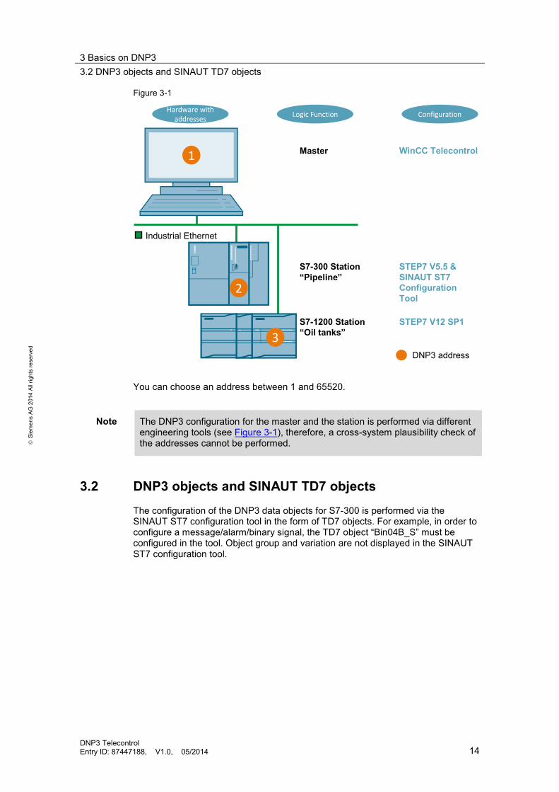
Figure 3-1
Industrial Ethernet
Master
S7-300 Station “Pipeline”
S7-1200 Station“Oil tanks”
WinCC Telecontrol
STEP7 V5.5 &SINAUT ST7 Configuration Tool
STEP7 V12 SP1
DNP3 address
1
2
3
ConfigurationHardware with addresses Logic Function
You can choose an address between 1 and 65520.
Note The DNP3 configuration for the master and the station is performed via different engineering tools (see Figure 3-1), therefore, a cross-system plausibility check of the addresses cannot be performed.
3.2 DNP3 objects and SINAUT TD7 objects
The configuration of the DNP3 data objects for S7-300 is performed via the SINAUT ST7 configuration tool in the form of TD7 objects. For example, in order to configure a message/alarm/binary signal, the TD7 object “Bin04B_S” must be configured in the tool. Object group and variation are not displayed in the SINAUT ST7 configuration tool.
3 Basics on DNP3 3.3 DNP3 classes
DNP3 Telecontrol Entry ID: 87447188, V1.0, 05/2014 15
S
iem
ens
AG 2
014
All r
ight
s re
serv
ed
Figure 3-2
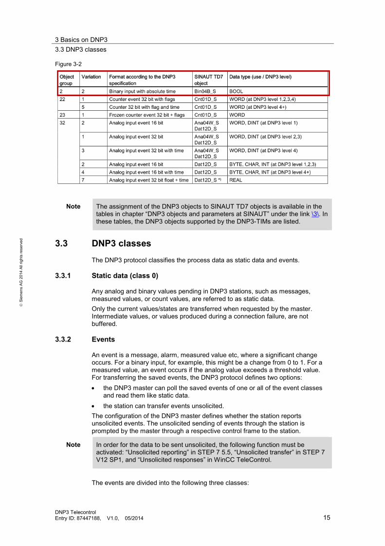
Note The assignment of the DNP3 objects to SINAUT TD7 objects is available in the tables in chapter “DNP3 objects and parameters at SINAUT” under the link \3\. In these tables, the DNP3 objects supported by the DNP3-TIMs are listed.
3.3 DNP3 classes
The DNP3 protocol classifies the process data as static data and events.
3.3.1 Static data (class 0)
Any analog and binary values pending in DNP3 stations, such as messages, measured values, or count values, are referred to as static data. Only the current values/states are transferred when requested by the master. Intermediate values, or values produced during a connection failure, are not buffered.
3.3.2 Events
An event is a message, alarm, measured value etc, where a significant change occurs. For a binary input, for example, this might be a change from 0 to 1. For a measured value, an event occurs if the analog value exceeds a threshold value. For transferring the saved events, the DNP3 protocol defines two options: • the DNP3 master can poll the saved events of one or all of the event classes
and read them like static data. • the station can transfer events unsolicited. The configuration of the DNP3 master defines whether the station reports unsolicited events. The unsolicited sending of events through the station is prompted by the master through a respective control frame to the station.
Note In order for the data to be sent unsolicited, the following function must be activated: “Unsolicited reporting” in STEP 7 5.5, “Unsolicited transfer” in STEP 7 V12 SP1, and “Unsolicited responses” in WinCC TeleControl.
The events are divided into the following three classes:

3 Basics on DNP3 3.4 Index
DNP3 Telecontrol Entry ID: 87447188, V1.0, 05/2014 16
S
iem
ens
AG 2
014
All r
ight
s re
serv
ed
Class 1 This class is recommended for critical events. All changes of a process value are stored in the event memory and immediately sent to the master.
Class 2 The class 2 events are handled in the same way as the class 1events; i.e., all changes of a process value are stored in the event memory and immediately sent to the master.
Class 3 Handling the class 3 events is a proprietary solution for the DNP3-TIMs and the CP 1243-1. Only the last change of a process value is stored in the event memory. The current, changed value is transferred to the control station when the control station polls the events of event class 3. Event class 3 is, for example, suitable for transferring count states, since only the last count value is of interest.
3.4 Index The DNP3 protocol specifies the index for characterizing one individual data point within a DNP3 object group. There are the following groups: binary input, analog input, counter input, control output and analog output. Within a DNP3 object group, each individual process value is addressed via a unique index. The DNP3 index is continuously assigned during configuration, starting with index 0.
Index assignment at S7-300 The data points transferred in the send and receive channels are numbered consecutively with rising index. The “Bin04B_S” data object, for example, contains 4 channels à 1 byte for sending binary data. In each channel, 8 data points are given a rising index according to the 8 bits. Channel 1 comprises index 0...7, channel 2 comprises index 8...15 etc.
Note For data objects with several channels, a non-configured channel also assigns an index. The “Bin04B_S” object, for example, contains 4 channels à 1 byte; i.e., it assigns 4 x 8 indices, which makes a total of 32 indices. If you have configured the “Bin04B_S” object with start index 0, and you wish to configure a second object of the same DNP3 object group, you should assign number 32 as the start index.
Note A table with the SINAUT objects and their index assignments is available in chapter “TD7 object, DNP3 object group and index assignment”, link \3\.
Index assignment at S7-1200 In TIA Portal, the index is counted up automatically when creating data points of the same type. You can also change the index manually. The TIA Portal ensures that the index is only assigned once per DNP3 object group.
3 Basics on DNP3 3.5 Group and variation
DNP3 Telecontrol Entry ID: 87447188, V1.0, 05/2014 17
S
iem
ens
AG 2
014
All r
ight
s re
serv
ed
3.5 Group and variation
Group The DNP3 protocol specifies object groups which in the SINAUT configuration tool correspond to the data objects. At TIA Portal, the object group is listed under “Type of data point”. Individual items of data or groups of data are addressed via data objects which differ depending on the data type (binary, analog, command, etc) and send or receive direction.
Variation The DNP3 object group specifies the respective data types. Within some data objects, the variation of the data format specifies the variation of the data format of the process value. Each object group has a typical set of variations. The most important variations specify the following data formats: • Counter, binary and analog values: with or without time stamp • Analog value formats: 16 or 32 bit, fixed point number or floating point value
3.6 Implementation level
The DNP3 protocol specifies implementation levels for the implementation of the protocol for the different DNP3 devices. Level 1 is the lowest level which only supports the basic functions. Level 2 supports more groups and variations than level 1. Additionally, level 2 and 3 also support time stamps and buffering for binary inputs. Level 4 and level 5 additionally support time stamps and buffering for analog input and counter input. The “DNP3 Device Profile” of each DNP3 module includes information on the highest level supported by this module. When configuring the stations, the highest implementation level supported by the master must be entered.
3.7 Assignment of terms
In STEP 7V5.5, STEP 7 V12 and in WinCC TeleControl partly different names are used for the same parameters. In order to facilitate the configuration, a table with the names of the parameters is available in German and another one in English.

3 Basics on DNP3 3.7 Assignment of terms
DNP3 Telecontrol Entry ID: 87447188, V1.0, 05/2014 18
S
iem
ens
AG 2
014
All r
ight
s re
serv
ed
German terms Table 3-1
WinCC TeleControl
SINAUT ST7 Projektierungstool
TIA Portal (STEP7 V12 SP1)
Verbindungsadresse Link Address
Teilnehmernr. Stationsadresse Master-Stationsadresse
Not displayed DNP3 Konformitäts-Stufe DNP3 level Variable Objekt Datenpunkt Klasse Ereignisklasse Ereignisklasse Index DNP3-Startindex Index der Datenpunkte Gruppe Objekt Name
(s. Hinweis am Ende der Tabelle)
Typ des Datenpunkts Variation Wird nicht angezeigt
Datenverarbeitungs-Modus
Endung „_S“ zum Senden, Endung „_R“ zum Empfangen im „Object Name“ z. B. Bin04B_S
Wird nicht angezeigt, da es vom „Type of data point“ erkennbar ist
Unaufgeforderte Rückmeldungen
Spontanes Melden (wird in STEP7 V5 konfiguriert und angezeigt)
Spontane Übertragung
English terms Table 3-2
WinCC TeleControl
SINAUT ST7 Configuration Tool
TIA Portal (STEP 7 V12 SP1)
Link address Subscriber no. Station address Master station address
Not displayed DNP3 conformity level DNP3 level Tag Object Data point Class Event class Event class Index DNP3 start index Data point index Group Object name
(see note at the end of the table)
Type of data point Variation Not displayed
Data processing mode
Suffix “_S” for sending, suffix “_R” for receiving in “Object Name” e.g. Bin04B_S
Not displayed since it can be recognized by “Type of data point”
Unsolicited responses Unsolicited reporting (configured and displayed in STEP 7 V5)
Unsolicited transfer
4 Program Overview 4.1 STEP 7 V5 project (S7-300)
DNP3 Telecontrol Entry ID: 87447188, V1.0, 05/2014 19
S
iem
ens
AG 2
014
All r
ight
s re
serv
ed
4 Program Overview In this chapter, the program structure of the application example is described. The supplied code contains the following files: • for the S7-300 station: STEP 7 V5 project, incl. SINAUT project • for the S7-1200 station: STEP 7 V12 project • for the DNP3 master and the visualization: WinCC project, incl. WinCC
TeleControl project • for the VPN configuration: SCT project and SCALANCE M configuration
4.1 STEP 7 V5 project (S7-300)
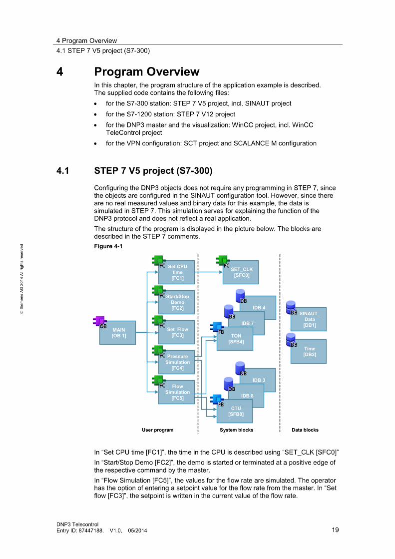
Configuring the DNP3 objects does not require any programming in STEP 7, since the objects are configured in the SINAUT configuration tool. However, since there are no real measured values and binary data for this example, the data is simulated in STEP 7. This simulation serves for explaining the function of the DNP3 protocol and does not reflect a real application. The structure of the program is displayed in the picture below. The blocks are described in the STEP 7 comments. Figure 4-1
IDB 4
IDB 7
User program System blocks Data blocks
MAIN[OB 1]
Set CPU time [FC1]
Start/Stop Demo [FC2]
Set Flow [FC3]
Pressure Simulation
[FC4]
Flow Simulation
[FC5]
SET_CLK[SFC0]
SINAUT_Data[DB1]
Time[DB2]
TON[SFB4]
IDB 3
IDB 8
CTU[SFB0]
In “Set CPU time [FC1]”, the time in the CPU is described using “SET_CLK [SFC0]” In “Start/Stop Demo [FC2]”, the demo is started or terminated at a positive edge of the respective command by the master. In “Flow Simulation [FC5]”, the values for the flow rate are simulated. The operator has the option of entering a setpoint value for the flow rate from the master. In “Set flow [FC3]”, the setpoint is written in the current value of the flow rate.

4 Program Overview 4.2 STEP 7 V12 project (S7-1200)
DNP3 Telecontrol Entry ID: 87447188, V1.0, 05/2014 20
S
iem
ens
AG 2
014
All r
ight
s re
serv
ed
Similar to the flow rate for “Flow Simulation [FC5]”, a pressure simulation is performed at “Pressure Simulation [FC4]”. In “SINAUT_Data [DB1]”, the PLC tags to be used for the TD7 objects were specified. The DT-type variable required for setting the CPU time was defined in “Time [DB2]”.
4.2 STEP 7 V12 project (S7-1200)
As for the S7-300 station, programming in STEP 7 is not necessary for configuring the DNP3 objects. The data objects are configured in the “Data points” field in STEP 7. However, since there are no real measured values and binary data for this example, the data was simulated in STEP 7. This simulation servers for explaining the function of the DNP3 protocol and does not reflect a real application. The structure of the program is displayed in the picture below. The blocks are described in the STEP 7 comments. Figure 4-2
IDB 2
IDB
User program System blocks Data blocks
MAIN[OB 1]
Timesync[FC1]
Oil level[FC5]
Temperature[FC7]
CP Time[DB1]
CP Data[DB3]
IEC_Timer
IDB 10
IEC_Counter
SimulationData[DB7]
In CP Time [DB1], the PLC tags required for the time synchronization were defined. The “CP Time.CPU time sync cycle” tag has a start value of five minutes (300s). After this time has elapsed, a trigger is set in “Timesync [FC1]” which writes the time of the DP in the CPU using the “WR_SYS_T Set time-of-day”. In the “Oil level [FC5]” and “Temperature [FC7]” blocks, the values for filling level and temperature are simulated. The tags required for this were defined in “Simulation Data [DB 7]”. In “CP_Data [DB3]”, the PLC tags were defined which are used for configuring the data points.

4 Program Overview 4.3 WinCC project (DNP3 master)
DNP3 Telecontrol Entry ID: 87447188, V1.0, 05/2014 21
S
iem
ens
AG 2
014
All r
ight
s re
serv
ed
4.3 WinCC project (DNP3 master)
In SIMATIC WinCC, the configuration of the HMI systems takes place. Additionally, the configuration of the DNP3 master is performed by the WinCC TeleControl add-on software. The DNP3 configuration of the master is described in detail in chapter 7. For the process data, one respective folder for each station was created in “Tag Management”. The names of the tags need not match those of the objects in the CPU configuration; however, it is important that the configuration of the objects matches the configuration in the CPU (group, variation, class etc.).
Figure 4-3
4.4 Overview of the data objects
The following figure gives you an overview of the data points configured in this application example. The configured objects in the SINAUT configuration tool don’t have names but numbers. The assignment of the WinCC objects to the TD7 objects in S7-300 is performed via: • the DNP3 object group (WinCC) and the TD7 object type (S7-300), see the
table with the assignment of the objects in Figure 3-1. • the index: the index in WinCC must match the index in the SINAUT
configuration tool. For example, the “Flow” object in WinCC (group 32, index 0) is the object 4 in S7-300 (Ana04W_S, Index 0), since the DNP3 group 32 corresponds to the TD7 object type Ana04W_S (see Figure 3-1) and the index for both objects is identical. In order to facilitate the assignments of the objects in this example, we have configured them so the order of the objects in the SINAUT configuration tool matches the order of the objects in WinCC. Hence, the fourth listed object in WinCC (“Flow” tag, group 32, index 0) corresponds to the fourth listed object in the SINAUT configuration tool (object 4, Ana04W_S, index 0). For the S7-1200 in this example, the name of the WinCC variable is equal to the name of the data point in TIA Portal. The TD7 object type for S7-300, or the data point type for S7-1200, shows which objects / data points are commands, binary, or analog values. The class shows whether it relates to data or events.

4 Program Overview 4.5 IP addresses in the example
DNP3 Telecontrol Entry ID: 87447188, V1.0, 05/2014 22
S
iem
ens
AG 2
014
All r
ight
s re
serv
ed
Figure 4-4
WinCC VariablesFor the S7-300 Station „Pipeline“
For the S7-1200 Station „Oil tanks“
S7-300 Station „Pipeline“ TD7 Objects
S7-1200 Station „Oil tanks “ Data points
4.5 IP addresses in the example
For the configuration of the example in LAN (see Figure 2-2) the following IP addresses are used. Table 4-1
Station Module IP address
Internal External
Master PG/PC 192.168.0.100/24 S7-300 TIM 3V-IE DNP3 192.168.0.101/24 S7-1200 CP 1243-1 DNP3 192.168.0.102/24
For the configuration via internet/VPN, the IP addresses need to be adjusted, as described in chapter 10.2.2. Here you use the IP addresses from chapter 8.
5 DNP3 Configuration for S7-300 5.1 Configuration with the SIMATIC Manager
DNP3 Telecontrol Entry ID: 87447188, V1.0, 05/2014 23
S
iem
ens
AG 2
014
All r
ight
s re
serv
ed
5 DNP3 Configuration for S7-300 Chapters 5, 6 and 7 show the necessary steps for DNP3 configuration of an S7-300, an S7-1200 and the WinCC TeleControl (master) in detail. If you only wish to test the completed configuration, go to chapter 9.
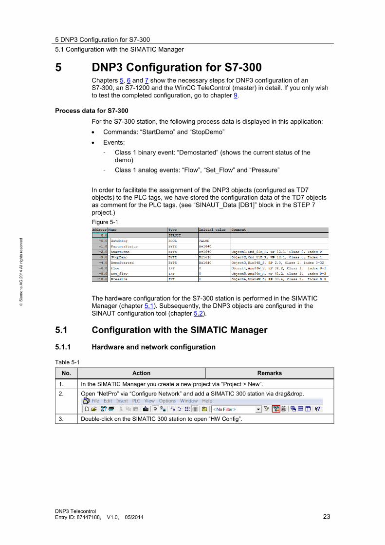
Process data for S7-300 For the S7-300 station, the following process data is displayed in this application: • Commands: “StartDemo” and “StopDemo” • Events:
– Class 1 binary event: “Demostarted” (shows the current status of the demo)
– Class 1 analog events: “Flow”, “Set_Flow” and “Pressure”
In order to facilitate the assignment of the DNP3 objects (configured as TD7 objects) to the PLC tags, we have stored the configuration data of the TD7 objects as comment for the PLC tags. (see “SINAUT_Data [DB1]” block in the STEP 7 project.) Figure 5-1
The hardware configuration for the S7-300 station is performed in the SIMATIC Manager (chapter 5.1). Subsequently, the DNP3 objects are configured in the SINAUT configuration tool (chapter 5.2).
5.1 Configuration with the SIMATIC Manager
5.1.1 Hardware and network configuration
Table 5-1
No. Action Remarks
1. In the SIMATIC Manager you create a new project via “Project > New”. 2. Open “NetPro” via “Configure Network” and add a SIMATIC 300 station via drag&drop.
3. Double-click on the SIMATIC 300 station to open “HW Config”.

5 DNP3 Configuration for S7-300 5.1 Configuration with the SIMATIC Manager
DNP3 Telecontrol Entry ID: 87447188, V1.0, 05/2014 24
S
iem
ens
AG 2
014
All r
ight
s re
serv
ed
No. Action Remarks
4. Insert the desired CPU and the DNP3-TIM. The DNP3-TIM module is available at “SIMATIC 300 > SINAUT ST7 > TIM IE > TIM3V-IE DNP3”.
5. Double-click on the TIM in your station. The window with the properties of the TIM opens. 6. Go to the “Interfaces” tab and select the
Ethernet interface.
7. Set the IP address of the TIM via “Properties”
and connect the interface with the “Ethernet(1)” subnet.
8. Ensure that the “Connection mode” has been
set to “DNP3 station”. Then click on “DNP3 Parameters” to make the DNP3 settings.
5 DNP3 Configuration for S7-300 5.1 Configuration with the SIMATIC Manager
DNP3 Telecontrol Entry ID: 87447188, V1.0, 05/2014 25
S
iem
ens
AG 2
014
All r
ight
s re
serv
ed
No. Action Remarks
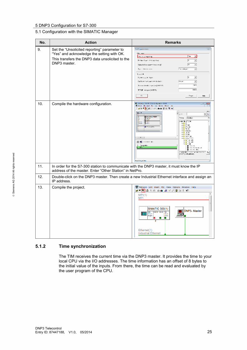
9. Set the “Unsolicited reporting” parameter to “Yes” and acknowledge the setting with OK. This transfers the DNP3 data unsolicited to the DNP3 master.
10. Compile the hardware configuration.
11. In order for the S7-300 station to communicate with the DNP3 master, it must know the IP
address of the master. Enter “Other Station” in NetPro. 12. Double-click on the DNP3 master. Then create a new Industrial Ethernet interface and assign an
IP address. 13. Compile the project.
5.1.2 Time synchronization
The TIM receives the current time via the DNP3 master. It provides the time to your local CPU via the I/O addresses. The time information has an offset of 8 bytes to the initial value of the inputs. From there, the time can be read and evaluated by the user program of the CPU.

5 DNP3 Configuration for S7-300 5.2 Configuration with the SINAUT ST7 configuration tool
DNP3 Telecontrol Entry ID: 87447188, V1.0, 05/2014 26
S
iem
ens
AG 2
014
All r
ight
s re
serv
ed
Table 5-2
No. Action Remarks
1. Open the properties of the TIM. Switch to the “Addresses” tab. Read the start value of the inputs. In this example, it is 256.
2. The time information is located in the I/O address as of:
start value of the inputs + 8 bytes In this example, this is the I/O address 264 (256 + 8).
3. Write the time to the CPU using the SFC0 “SET_CLCK” block.
See the “Set CPU Time” [FC1] block in the application example.
Note Further information on the time synchronization is available in the chapter “Time synchronization of S7-CPUs” (link \3\)
5.2 Configuration with the SINAUT ST7 configuration tool
5.2.1 Connection configuration
Table 5-3
No. Action Remarks
1. Start the SINAUT ST7 configuration tool via: “Start > all programs > Siemens Automation > SIMATIC > SINAUT ST7 > SINAUT ST7configuration”
2. Open the STEP 7 project which you have created in chapter 5.1. 3. Select “Connection Configuration” and start
with OK.

5 DNP3 Configuration for S7-300 5.2 Configuration with the SINAUT ST7 configuration tool
DNP3 Telecontrol Entry ID: 87447188, V1.0, 05/2014 27
S
iem
ens
AG 2
014
All r
ight
s re
serv
ed
No. Action Remarks
4. In the right window pane the possible connections are displayed which result from the network configuration in “NetPro”. Select the desired connections via “right mouse button on the connection > Add”.
5. The configured connection is shown in the left
window pane.
6. Save this configuration and go to the
“Subscriber Administration” dialog.
5.2.2 Subscriber administration
Table 5-4
No. Action Remarks
1. “Subscriber Administration” lists all of the subscribers.
2. You have the option of changing the subscriber number. However, is not required.
Select the desired subscriber from “Change subscriber No” via the right mouse button. Then enter a new subscriber number.

5 DNP3 Configuration for S7-300 5.2 Configuration with the SINAUT ST7 configuration tool
DNP3 Telecontrol Entry ID: 87447188, V1.0, 05/2014 28
S
iem
ens
AG 2
014
All r
ight
s re
serv
ed
No. Action Remarks
3. Select the “All Destination Subscribers” field and select the DNP3 master in the right window pane. Then enter the highest conformity level supported by your DNP3 master.
5.2.3 Configuring the SINAUT TD7 objects
Table 5-5
No. Action Remarks
1. In the left window pane you mark the TIM module under “TIMs with TD7onTIM” and then click on the TD7onTIM library icon.
2. The window with the “TD7onTIM library”
opens. Select the object you wish to configure and then click on “Paste into Project”. Then close the library with “Close”.
3. The objects now inserted in the project are listed in the left and right window pane. Now you can configure these objects. In the right window pane you select the data object you wish to configure.
5 DNP3 Configuration for S7-300 5.2 Configuration with the SINAUT ST7 configuration tool
DNP3 Telecontrol Entry ID: 87447188, V1.0, 05/2014 29
S
iem
ens
AG 2
014
All r
ight
s re
serv
ed
No. Action Remarks
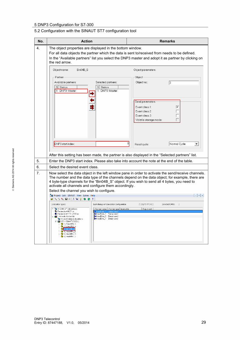
4. The object properties are displayed in the bottom window. For all data objects the partner which the data is sent to/received from needs to be defined. In the “Available partners” list you select the DNP3 master and adopt it as partner by clicking on the red arrow.
After this setting has been made, the partner is also displayed in the “Selected partners” list.
5. Enter the DNP3 start index. Please also take into account the note at the end of the table. 6. Select the desired event class.
7. Now select the data object in the left window pane in order to activate the send/receive channels. The number and the data type of the channels depend on the data object; for example, there are 4 byte-type channels for the “Bin04B_S” object. If you wish to send all 4 bytes, you need to activate all channels and configure them accordingly. Select the channel you wish to configure.
5 DNP3 Configuration for S7-300 5.2 Configuration with the SINAUT ST7 configuration tool
DNP3 Telecontrol Entry ID: 87447188, V1.0, 05/2014 30
S
iem
ens
AG 2
014
All r
ight
s re
serv
ed
No. Action Remarks
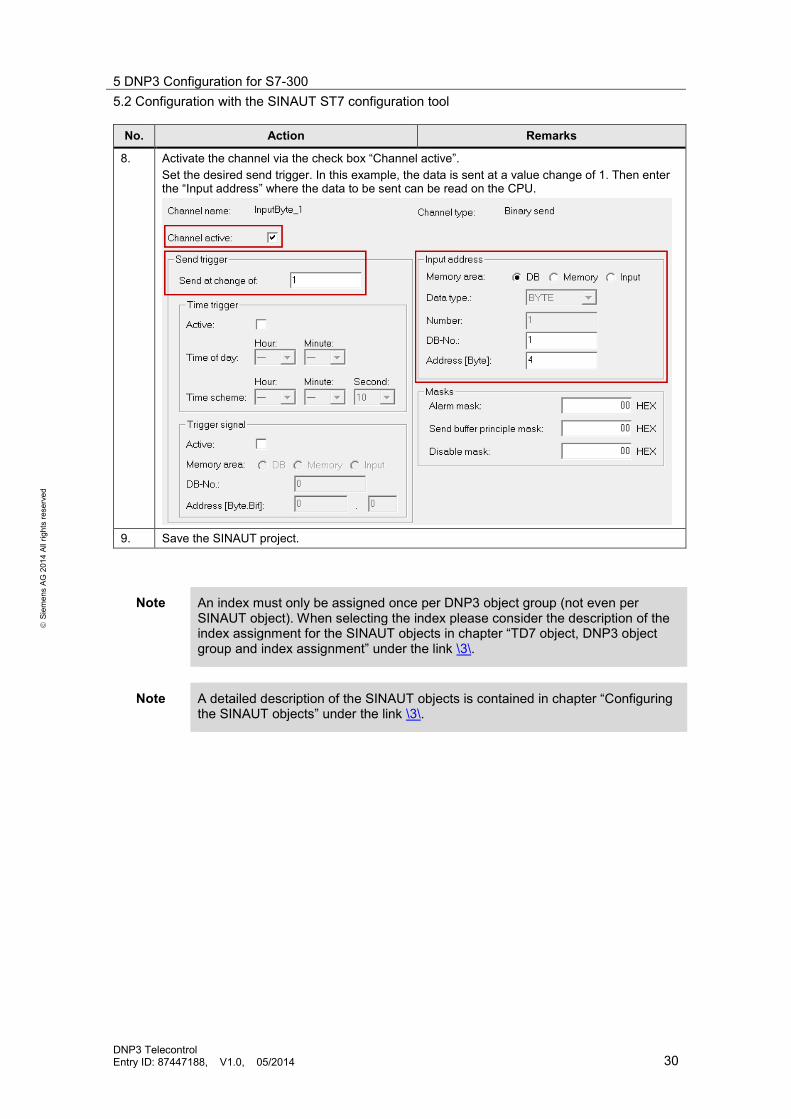
8. Activate the channel via the check box “Channel active”. Set the desired send trigger. In this example, the data is sent at a value change of 1. Then enter the “Input address” where the data to be sent can be read on the CPU.
9. Save the SINAUT project.
Note An index must only be assigned once per DNP3 object group (not even per SINAUT object). When selecting the index please consider the description of the index assignment for the SINAUT objects in chapter “TD7 object, DNP3 object group and index assignment” under the link \3\.
Note A detailed description of the SINAUT objects is contained in chapter “Configuring the SINAUT objects” under the link \3\.
6 DNP3 Configuration for S7-1200 6.1 Device configuration
DNP3 Telecontrol Entry ID: 87447188, V1.0, 05/2014 31
S
iem
ens
AG 2
014
All r
ight
s re
serv
ed
6 DNP3 Configuration for S7-1200 The configuration of the hardware and the DNP3 configuration for the S7-1200 is performed in STEP 7 V12 SP1. No additional tool is required.
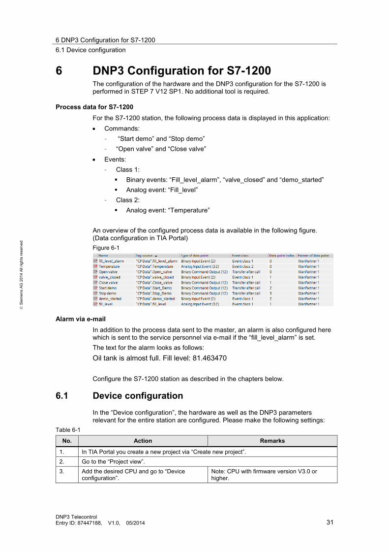
Process data for S7-1200 For the S7-1200 station, the following process data is displayed in this application: • Commands:
– “Start demo” and “Stop demo” – “Open valve” and “Close valve”
• Events: – Class 1: Binary events: “Fill_level_alarm”, “valve_closed” and “demo_started” Analog event: “Fill_level”
– Class 2: Analog event: “Temperature”
An overview of the configured process data is available in the following figure. (Data configuration in TIA Portal) Figure 6-1
Alarm via e-mail In addition to the process data sent to the master, an alarm is also configured here which is sent to the service personnel via e-mail if the “fill_level_alarm” is set. The text for the alarm looks as follows: Oil tank is almost full. Fill level: 81.463470 Configure the S7-1200 station as described in the chapters below.
6.1 Device configuration In the “Device configuration”, the hardware as well as the DNP3 parameters relevant for the entire station are configured. Please make the following settings:
Table 6-1
No. Action Remarks
1. In TIA Portal you create a new project via “Create new project”. 2. Go to the “Project view”. 3. Add the desired CPU and go to “Device
configuration”. Note: CPU with firmware version V3.0 or higher.
6 DNP3 Configuration for S7-1200 6.1 Device configuration
DNP3 Telecontrol Entry ID: 87447188, V1.0, 05/2014 32
S
iem
ens
AG 2
014
All r
ight
s re
serv
ed
No. Action Remarks
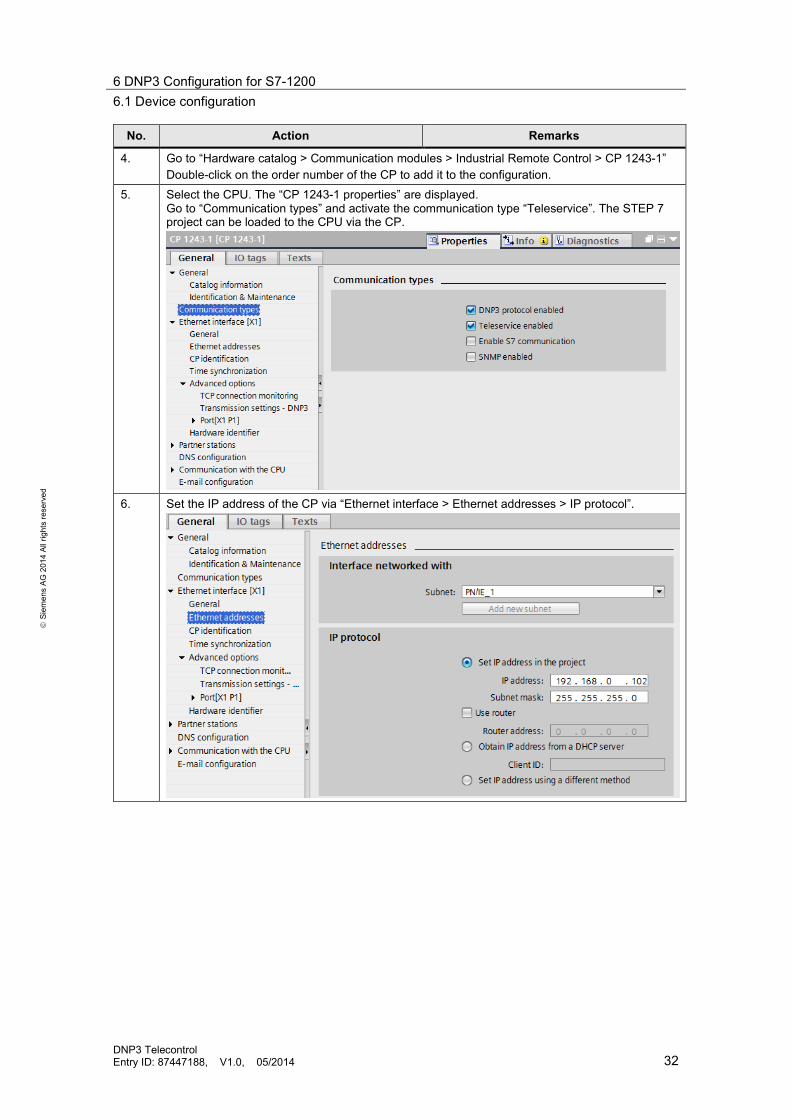
4. Go to “Hardware catalog > Communication modules > Industrial Remote Control > CP 1243-1” Double-click on the order number of the CP to add it to the configuration.
5. Select the CPU. The “CP 1243-1 properties” are displayed. Go to “Communication types” and activate the communication type “Teleservice”. The STEP 7 project can be loaded to the CPU via the CP.
6. Set the IP address of the CP via “Ethernet interface > Ethernet addresses > IP protocol”.

6 DNP3 Configuration for S7-1200 6.1 Device configuration
DNP3 Telecontrol Entry ID: 87447188, V1.0, 05/2014 33
S
iem
ens
AG 2
014
All r
ight
s re
serv
ed
No. Action Remarks
7. Go to “CP identification” and enter the station address (DNP3 address). In this application example, the station address for the S7-1200 station is number 3, see Figure 3-1. Note this address since you need it for configuring the master.
When selecting the station address please take into account the notes in chapter 3.1.
8. Go to “Time synchronization” to synchronize the time of the CP from the DNP3 master. Select the “Activate time-of-day synchronization” checkbox and set the desired synchronization cycle and time interval.

6 DNP3 Configuration for S7-1200 6.1 Device configuration
DNP3 Telecontrol Entry ID: 87447188, V1.0, 05/2014 34
S
iem
ens
AG 2
014
All r
ight
s re
serv
ed
No. Action Remarks
9. Go to “Transmission settings - DNP3”. Make sure that “Unsolicited transfer” is active. (Default settings)
10. Go to “Partner stations” and enter the “Master station address” according to Figure 3-1. Then
enter the IP address of the DNP3 masters in the “Partner IP address” field.
6 DNP3 Configuration for S7-1200 6.2 Data point configuration
DNP3 Telecontrol Entry ID: 87447188, V1.0, 05/2014 35
S
iem
ens
AG 2
014
All r
ight
s re
serv
ed
No. Action Remarks
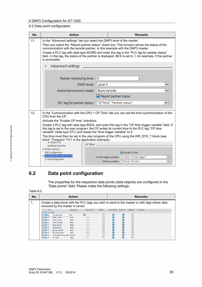
11. In the “Advanced settings” tab you select the DNP3 level of the master. Then you select the “Report partner status” check box. This function shows the status of the communication with the remote partner, in this example with the DNP3 master. Create a PLC tag with data type WORD and enter this tag in the “PLC tag for partner status” field. In this tag, the status of the partner is displayed. Bit 0 is set to 1, for example, if the partner is accessible.
12. In the “Communication with the CPU > CP Time” tab you can set the time synchronization of the
CPU from the CP. Activate the “Enable CP time” checkbox. Create a PLC tag with data type BOOL and enter this tag in the “CP time trigger variable” field. If this tag is set in the user program, the CP writes its current time to the PLC tag “CP time variable” (data type DTL) and resets the "time trigger variable" to 0. The time must then be set in the user program of the CPU using the WR_SYS_T block (see block “Timesync” FC1 in the application example).
6.2 Data point configuration The properties for the respective data points (data objects) are configured in the “Data points” field. Please make the following settings:
Table 6-2
No. Action Remarks
1. Create a data block with the PLC tags you wish to send to the master or with tags where data received by the master is saved.

6 DNP3 Configuration for S7-1200 6.2 Data point configuration
DNP3 Telecontrol Entry ID: 87447188, V1.0, 05/2014 36
S
iem
ens
AG 2
014
All r
ight
s re
serv
ed
No. Action Remarks
2. In the project navigation you go to “Local modules > CP 1243-1” and double-click on the “Data points” field.
3. The “Data point and alarm configuration” window opens.
Double-click on “Add new” to add a new data point.
4. Click on the arrow in “Tag source”.

6 DNP3 Configuration for S7-1200 6.2 Data point configuration
DNP3 Telecontrol Entry ID: 87447188, V1.0, 05/2014 37
S
iem
ens
AG 2
014
All r
ight
s re
serv
ed
No. Action Remarks
5. Select the data block where you saved the PLC tag you wish to send to the DNP3 master. Select the tag and click on the green check mark to accept the tag.
6. The tag has been added. TIA Portal adopts the tag name as the data point name.
Make a selection in “Type of data point”. In this example, Binary Input Event(2). Note: apart from the type of the data point, the DNP3 object group is shown in brackets. In this example it is n object from group 2. You need this information for configuring the tag at the DNP3 master. (See chapter 7.5). The groups are defined in the DNP3 protocol. In the data point configuration only those groups are displayed which match the type of the configured tag.
7. Select the desired “Event class”.
Note: the “Data point index” is automatically assigned by the TIA Portal. You need the index number for the configuration of the tag at the DNP3 master. (see chapter 7.5)
8. Select the partner to which the data shall be sent.

6 DNP3 Configuration for S7-1200 6.2 Data point configuration
DNP3 Telecontrol Entry ID: 87447188, V1.0, 05/2014 38
S
iem
ens
AG 2
014
All r
ight
s re
serv
ed
No. Action Remarks
9. The bottom window pane of the TIA Portal displays the properties of the data point. Go to the “Trigger” tab. Select the checkbox for the type of the trigger you wish to configure. In this example, the data point is triggered if the data changes by 1. (In this case the value cannot be adjusted since it is a binary tag.)
10. Compile and save the TIA project.
Note An overview of the DNP3 object types supported by CP 1243-1 DNP3 is available in chapter “Data point types” under the link \4\.
6 DNP3 Configuration for S7-1200 6.3 E-mail configuration
DNP3 Telecontrol Entry ID: 87447188, V1.0, 05/2014 39
S
iem
ens
AG 2
014
All r
ight
s re
serv
ed
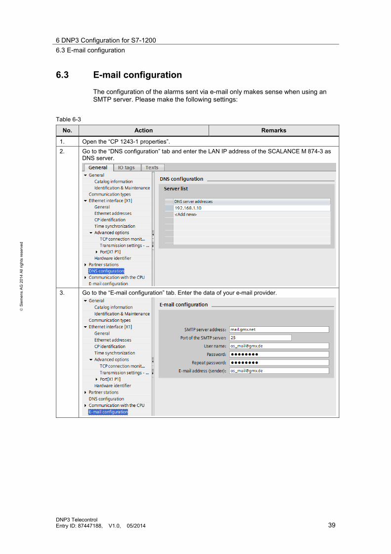
6.3 E-mail configuration The configuration of the alarms sent via e-mail only makes sense when using an SMTP server. Please make the following settings:
Table 6-3
No. Action Remarks
1. Open the “CP 1243-1 properties”. 2. Go to the “DNS configuration” tab and enter the LAN IP address of the SCALANCE M 874-3 as
DNS server.
3. Go to the “E-mail configuration” tab. Enter the data of your e-mail provider.

6 DNP3 Configuration for S7-1200 6.3 E-mail configuration
DNP3 Telecontrol Entry ID: 87447188, V1.0, 05/2014 40
S
iem
ens
AG 2
014
All r
ight
s re
serv
ed
No. Action Remarks
4. In the project navigation you go to “Alarms” via “Local modules > CP 1243-1”.
5. Double-click on “Add new” to add a new message/alarm.
6. In the bottom window pane of the TIA Portal, the properties of the alarm are displayed.
Enter the receiver address, subject and text for the e-mail. Note: string “$$” is the wildcard for the value of the PLC tag. (If the trigger of the alarms has been set to “Use PLC tag”. (See step below).

6 DNP3 Configuration for S7-1200 6.3 E-mail configuration
DNP3 Telecontrol Entry ID: 87447188, V1.0, 05/2014 41
S
iem
ens
AG 2
014
All r
ight
s re
serv
ed
No. Action Remarks
7. Go to the “Trigger” tab. (1) Select the type of the trigger in the drop-down menu. In this example, a PLC tag was used
as trigger. (2) In the drop-down list you select the PLC tag which is used as trigger. (3) It is recommended to activate the “Enable status identifier” checkbox and select a DWORD-
type PLC tag in “External status”. In this tag the status messages from the SMTP server are displayed.
(4) Select the “Include value” checkbox and in the “PLC tag for value” field you select the PLC tag to be sent with the alarm.
8. Compile and save the TIA project.
1
2 3
4
7 DNP3 Configuration for DNP3 Master 7.1 Inserting the DNP3 driver
DNP3 Telecontrol Entry ID: 87447188, V1.0, 05/2014 42
S
iem
ens
AG 2
014
All r
ight
s re
serv
ed
7 DNP3 Configuration for DNP3 Master The DNP3 configuration of the master is performed in SIMATIC WinCC. The Add-on Software WinCC TeleControl is necessary for this. Make the settings in WinCC as described in the chapters below.
7.1 Inserting the DNP3 driver Table 7-1
No. Action Remarks
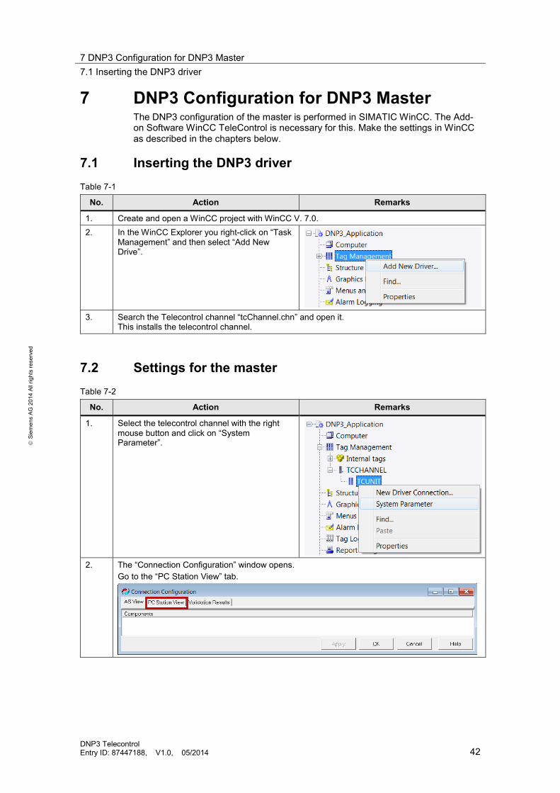
1. Create and open a WinCC project with WinCC V. 7.0. 2. In the WinCC Explorer you right-click on “Task
Management” and then select “Add New Drive”.
3. Search the Telecontrol channel “tcChannel.chn” and open it.
This installs the telecontrol channel.
7.2 Settings for the master Table 7-2
No. Action Remarks
1. Select the telecontrol channel with the right mouse button and click on “System Parameter”.
2. The “Connection Configuration” window opens.
Go to the “PC Station View” tab.

7 DNP3 Configuration for DNP3 Master 7.3 Settings for the connection node TIM / CP
DNP3 Telecontrol Entry ID: 87447188, V1.0, 05/2014 43
S
iem
ens
AG 2
014
All r
ight
s re
serv
ed
No. Action Remarks
3. Enter the “Link Address” for the DNP3 master according to Figure 3-1.
Click “Apply” to apply the setting.
7.3 Settings for the connection node TIM / CP
In order to establish the communication with the station, the properties of the TIM / CP must be known to the master. Make the necessary settings:
Table 7-3
No. Action Remarks
1. (1) Go to the “AS View” tab. All RTUs and their communication devices (TIMs, CPs) connected to the DNP3 master are configured here.
(2) Right-click into the empty space in the “Components” window pane. (3) Select “‘Add DNPCONN' AS Source Node” in the dialog field.
Note: all of the DNP RTUs need to be connected via one or two DNP connections. First, the DNP connections (DNPCONN) and then the DNP RTUs (DNPRTU) need to be configured.
1
2
3

7 DNP3 Configuration for DNP3 Master 7.4 Settings for the CPU
DNP3 Telecontrol Entry ID: 87447188, V1.0, 05/2014 44
S
iem
ens
AG 2
014
All r
ight
s re
serv
ed
No. Action Remarks
2. The “DNPCONN AS properties” dialog field is displayed. (1) In the “AS Node Name” field you enter a name for the DNP connection node (CP or TIM). (2) In “Protocol Type” you activate the “TCP” radio button. (3) In the “Connection Address” field you enter the IP address of the TIM or the CP.
Apply the settings with OK.
3. Repeat the steps 2-3 for the CP.
7.4 Settings for the CPU
At the DNP3 master, settings need to be made for each DNP3 station. These settings specify, for example, how the master shall treat the events of the various classes for this station. Please make the following settings:
1
2
3
7 DNP3 Configuration for DNP3 Master 7.4 Settings for the CPU
DNP3 Telecontrol Entry ID: 87447188, V1.0, 05/2014 45
S
iem
ens
AG 2
014
All r
ight
s re
serv
ed
Table 7-4
No. Action Remarks
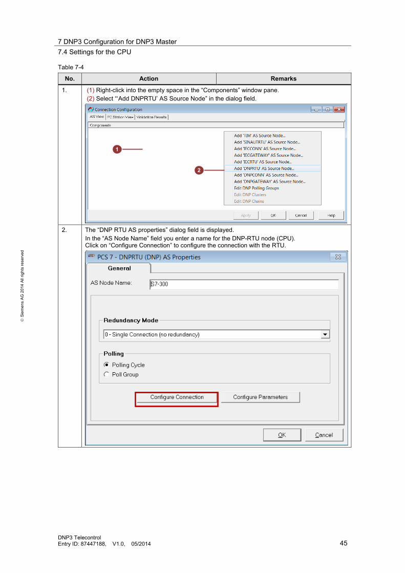
1. (1) Right-click into the empty space in the “Components” window pane. (2) Select “‘Add DNPRTU’ AS Source Node” in the dialog field.
2. The “DNP RTU AS properties” dialog field is displayed.
In the “AS Node Name” field you enter a name for the DNP-RTU node (CPU). Click on “Configure Connection” to configure the connection with the RTU.
1
2

7 DNP3 Configuration for DNP3 Master 7.4 Settings for the CPU
DNP3 Telecontrol Entry ID: 87447188, V1.0, 05/2014 46
S
iem
ens
AG 2
014
All r
ight
s re
serv
ed
No. Action Remarks
3. Enter the “Link Address” for the CPU according to Figure 3-1. Then select the DNP connection node from the drop-down list and acknowledge the settings with OK.

7 DNP3 Configuration for DNP3 Master 7.4 Settings for the CPU
DNP3 Telecontrol Entry ID: 87447188, V1.0, 05/2014 47
S
iem
ens
AG 2
014
All r
ight
s re
serv
ed
No. Action Remarks
4. Click on “Configure Parameters”. The window with the DNP parameters for this station is displayed. Activate the “Unsolicited Responses” function for class 1 and 3. In this application example, the class 2 events shall be archived in the CPU and only be sent after requested from the master. Deactivate the “Integrity Poll on Class xData Bit set” checkbox.

7 DNP3 Configuration for DNP3 Master 7.5 Tag configuration
DNP3 Telecontrol Entry ID: 87447188, V1.0, 05/2014 48
S
iem
ens
AG 2
014
All r
ight
s re
serv
ed
No. Action Remarks
5. Close all windows with OK. The system variables are created and displayed in the right window.
6. Repeat the steps 1-5 for the S7-1200 CPU.
Note The system tags are automatically created after the TIM (or CP) and the CPU were configured in “System Parameter”. The description of this tag is available in the “User manual for WinCC TeleControl”, which was supplied with the WinCC TeleControl software.
7.5 Tag configuration In order for the master to be able to send/receive the DNP3 objects, they need to be configured in the “Tag Management” field. Please make the following settings:
Table 7-5
No. Action Remarks
1. In “Tag Management” > TCCHANNEL > TCUNIT > Telecontrol” you right-click into the right window pane. Then select “New Tag”.

7 DNP3 Configuration for DNP3 Master 7.5 Tag configuration
DNP3 Telecontrol Entry ID: 87447188, V1.0, 05/2014 49
S
iem
ens
AG 2
014
All r
ight
s re
serv
ed
No. Action Remarks
2. The “Tag properties” dialog field is displayed. (1) Assign a name to the tag. (2) Select the desired data type from the drop-down list. (3) Click on the “Select” button.
1
2
3

7 DNP3 Configuration for DNP3 Master 7.5 Tag configuration
DNP3 Telecontrol Entry ID: 87447188, V1.0, 05/2014 50
S
iem
ens
AG 2
014
All r
ight
s re
serv
ed
No. Action Remarks
3. The system configuration for this tag is displayed. (1) In the “AS Node” field, you select the CPU to/from which this tag is to be sent/received. (2) Select the desired “Data Processing Mode”
Reading RP process data (receiving data from the CPU) Writing WP process data (sending data to the CPU)
(3) Select the event class in “Class”. (4) Enter the index. Please consider the Notes in chapter 3.4.
(5) Select the group. (The groups are defined in the DNP3 protocol. Here, only those groups are displayed which match the type of the configured tag.) (6) Select the variation. (7) Apply the settings with OK.
Note Class, index, group and variation of the tag must match the settings in the CPU. For the S7-300, these settings are made in the SINAUT configuration tool, for the S7-1200 in the data point configuration in STEP 7 V12 (see chapter 5.2.3 for the S7-300 and chapter 6.2 for the S7-1200).
1 2
4
5
6
3
7
8 VPN Tunnel Configuration 7.5 Tag configuration
DNP3 Telecontrol Entry ID: 87447188, V1.0, 05/2014 51
S
iem
ens
AG 2
014
All r
ight
s re
serv
ed
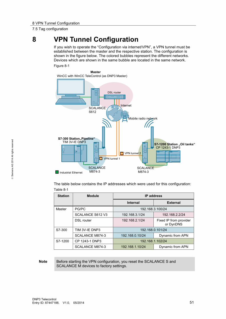
8 VPN Tunnel Configuration If you wish to operate the “Configuration via internet/VPN”, a VPN tunnel must be established between the master and the respective station. The configuration is shown in the figure below. The colored bubbles represent the different networks. Devices which are shown in the same bubble are located in the same network. Figure 8-1
VPN tunnel 2
VPN tunnel 1
SCALANCEM874-3
SCALANCEM874-3Industrial Ethernet
Master
S7-300 Station„Pipeline“
S7-1200 Station „Oil tanks“
WinCC with WinCC TeleControl (as DNP3 Master)
CP 1243-1 DNP3
TIM 3V-IE DNP3
Mobile radio network
SCALANCE S612
DSL router
Internet
The table below contains the IP addresses which were used for this configuration: Table 8-1
Station Module IP address
Internal External
Master PG/PC 192.168.3.100/24 SCALANCE S612 V3 192.168.3.1/24 192.168.2.2/24 DSL router 192.168.2.1/24 Fixed IP from provider
or DynDNS S7-300 TIM 3V-IE DNP3 192.168.0.101/24
SCALANCE M874-3 192.168.0.10/24 Dynamic from APN S7-1200 CP 1243-1 DNP3 192.168.1.102/24
SCALANCE M874-3 192.168.1.10/24 Dynamic from APN
Note Before starting the VPN configuration, you reset the SCALANCE S and SCALANCE M devices to factory settings.

8 VPN Tunnel Configuration 8.1 Configuration with the SCT tool
DNP3 Telecontrol Entry ID: 87447188, V1.0, 05/2014 52
S
iem
ens
AG 2
014
All r
ight
s re
serv
ed
Note At the DSL router, you set a port-forwarding for port 500 and port 4500 to the external IP address of SCALANCE S612.
8.1 Configuration with the SCT tool
The certificates for the VPN tunnel are created using the Security Configuration Tool (SCT). The configuration of SCALANCE S612 is also performed in the SCT. Make the settings as described in the subchapters below:
8.1.1 Creating project and modules
Table 8-2
No. Action Remarks
1. Open the Security Configuration Tool (SCT) via: “Start > “All programs” > SIEMENS Automation > SIMATIC > Security > Security Configuration Tool”.
2. Create a new project via “Project > New”.
3. In the following dialog you create a new user
with user name and respective password. Confirm the dialog with OK.
4. The “Selection of a module or software
configuration” window opens. The first module you configure is the SCALANCE S: (1) Select the product type and version of your
module. (In this application example, SCALANCE S612, firmware version V4 is used.)
(2) Enter a name and the MAC address for this module. (The MAC address is printed on the front of the SCALANCE S.)
(3) Select “Routing mode” and enter the internal and external IP address according to Table 8-1.
(4) Click OK to confirm the settings.
1
3
4
1
1
2 2 3
3

8 VPN Tunnel Configuration 8.1 Configuration with the SCT tool
DNP3 Telecontrol Entry ID: 87447188, V1.0, 05/2014 53
S
iem
ens
AG 2
014
All r
ight
s re
serv
ed
No. Action Remarks
5. Enter the internal IP address of your DSL router as “Standard router” in the module line. (See Table 8-1).
6. Insert a new module with “Insert -> Module”.
7. Configure the SCALANCE M874-3 for the
S7-300 station as follows: (1) Select product type and module as in the
picture. (2) Assign a name and enter the internal IP
address according to Table 8-1. (3) Click OK to confirm the settings.
Note: the SCT requires an external IP address for the SCALANCE M874-3. Since this IP address is assigned dynamically by the mobile service provider, it cannot be entered here. For this reason, just use the default IP address of the SCT (here: 192.168.10.1).
4 8. Repeat steps no. 6-7 to configure the SCALANCE M874-3 of the S7-1200 station.
The configured modules are displayed at “All Modules”.
1
2
3
1
1
2
8 VPN Tunnel Configuration 8.1 Configuration with the SCT tool
DNP3 Telecontrol Entry ID: 87447188, V1.0, 05/2014 54
S
iem
ens
AG 2
014
All r
ight
s re
serv
ed
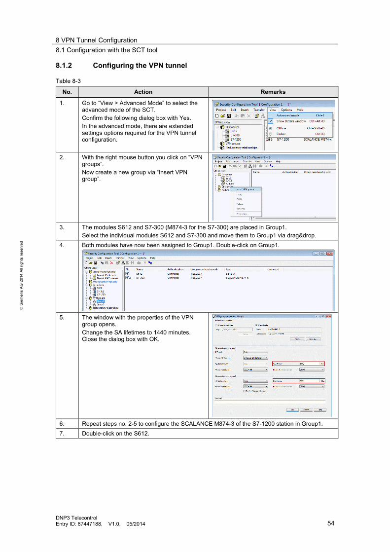
8.1.2 Configuring the VPN tunnel
Table 8-3
No. Action Remarks
1. Go to “View > Advanced Mode” to select the advanced mode of the SCT. Confirm the following dialog box with Yes. In the advanced mode, there are extended settings options required for the VPN tunnel configuration.
2. With the right mouse button you click on “VPN
groups”. Now create a new group via “Insert VPN group”.
3. The modules S612 and S7-300 (M874-3 for the S7-300) are placed in Group1.
Select the individual modules S612 and S7-300 and move them to Group1 via drag&drop. 4. Both modules have now been assigned to Group1. Double-click on Group1.
5. The window with the properties of the VPN
group opens. Change the SA lifetimes to 1440 minutes. Close the dialog box with OK.
6. Repeat steps no. 2-5 to configure the SCALANCE M874-3 of the S7-1200 station in Group1. 7. Double-click on the S612.

8 VPN Tunnel Configuration 8.1 Configuration with the SCT tool
DNP3 Telecontrol Entry ID: 87447188, V1.0, 05/2014 55
S
iem
ens
AG 2
014
All r
ight
s re
serv
ed
No. Action Remarks
8. The window with the properties of the SCALANCE S612 opens. 1. Go to the VPN tab. 2. Set the “Time interval” for the Dead-Peer-Detection to 180 seconds. This function prevents the display of obsolete VPN tunnels in online view. 3. The SCALANCE S waits for the connection of the SCALANCE M874-3. Change the permission to initiate the connection accordingly to “Wait for partner (responder)”. 4. Enter the fixed IP address (or the domain name) of your DSL routers in the “WAN IP address/FQDN” field. 5. Click on OK to confirm the settings.
Note: the Dead-Peer-Detection time interval must be set higher than in M874-3. The default setting for the M874-3 is 150 seconds.
9. Save your project.
Note Alternatively you can configure all modules in the same group. This makes the VPN properties and the certificates for all SCALANCE M identical.
Note A group represents a VPN connection. Only nodes which are part of this group can participate in the VNP communication.
8.1.3 Loading the configuration
Table 8-4
No. Action Remarks
1. Set the IP address of the PG/PC to 192.168.2.100, for example.
The IP address of the PG/PC must be located in the same network as the IP address of the SCALANCE S612, via which the module is loaded.
2. Connect the PC/PG with the external port of the SCALANCE S.
The SCALANCE S has no default IP address. The download occurs via the given MAC address. Note: the SCALANCE S can also be loaded via the internal port.
3. Download the configuration to the SCALANCE S. Select the line of the SCALANCE S module in the right window pane of the SCT and click on “Transfer to module”.
1
2
3 4
8 VPN Tunnel Configuration 8.2 Configuration with the SCALANCE M874-3 WBM
DNP3 Telecontrol Entry ID: 87447188, V1.0, 05/2014 56
S
iem
ens
AG 2
014
All r
ight
s re
serv
ed
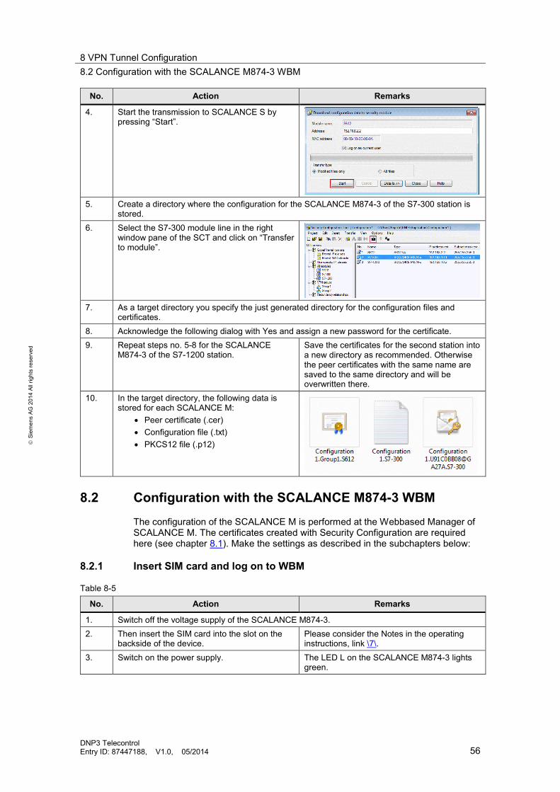
No. Action Remarks
4. Start the transmission to SCALANCE S by pressing “Start”.
5. Create a directory where the configuration for the SCALANCE M874-3 of the S7-300 station is
stored. 6. Select the S7-300 module line in the right
window pane of the SCT and click on “Transfer to module”.
7. As a target directory you specify the just generated directory for the configuration files and
certificates. 8. Acknowledge the following dialog with Yes and assign a new password for the certificate. 9. Repeat steps no. 5-8 for the SCALANCE
M874-3 of the S7-1200 station. Save the certificates for the second station into a new directory as recommended. Otherwise the peer certificates with the same name are saved to the same directory and will be overwritten there.
10. In the target directory, the following data is stored for each SCALANCE M:
• Peer certificate (.cer) • Configuration file (.txt) • PKCS12 file (.p12)
8.2 Configuration with the SCALANCE M874-3 WBM The configuration of the SCALANCE M is performed at the Webbased Manager of SCALANCE M. The certificates created with Security Configuration are required here (see chapter 8.1). Make the settings as described in the subchapters below:
8.2.1 Insert SIM card and log on to WBM
Table 8-5
No. Action Remarks
1. Switch off the voltage supply of the SCALANCE M874-3. 2. Then insert the SIM card into the slot on the
backside of the device. Please consider the Notes in the operating instructions, link \7\.
3. Switch on the power supply. The LED L on the SCALANCE M874-3 lights green.

8 VPN Tunnel Configuration 8.2 Configuration with the SCALANCE M874-3 WBM
DNP3 Telecontrol Entry ID: 87447188, V1.0, 05/2014 57
S
iem
ens
AG 2
014
All r
ight
s re
serv
ed
No. Action Remarks
4. Set the IP address of the PG/PC to 192.168.1.100.
The IP address of the PG/PC must be located in the same network as the default IP address of the SCALANCE M874-3. According to the factory settings, the SCALANCE M874-3 has the address 192.168.1.1.
5. Connect the PC/PG with LAN port P1 of the SCALANCE M. 6. Start a browser and specify the IP address of SCALANCE M (192.168.1.1) as the address. 7. The Web Based Management (WBM) of
SCALANCE M is displayed.
If the Web Based Management of the SCALANCE M is not displayed, ensure that the requirements in chapter 3.1, link \9\ have been met.
8. Enter user name and password. Acknowledge the entry with “Login” and acknowledge the message with OK. The default settings are: User name: admin Password: admin
9. Assign a new password and acknowledge the
settings with “Set Values”.
8.2.2 Setting the access for the mobile radio network
Table 8-6
No. Action Remarks
1. Go to “Interfaces > Mobile”. 2. Activate the mobile radio interface via the
“Enable Mobile Network Interface” checkbox. Enter the PIN of the SIM card and acknowledge the settings with “Set Values”.
3. Go to the “Operator” tab.
When the APN for your SIM card is displayed in the list, make sure that the “Enabled” checkbox has been activated.
8 VPN Tunnel Configuration 8.2 Configuration with the SCALANCE M874-3 WBM
DNP3 Telecontrol Entry ID: 87447188, V1.0, 05/2014 58
S
iem
ens
AG 2
014
All r
ight
s re
serv
ed
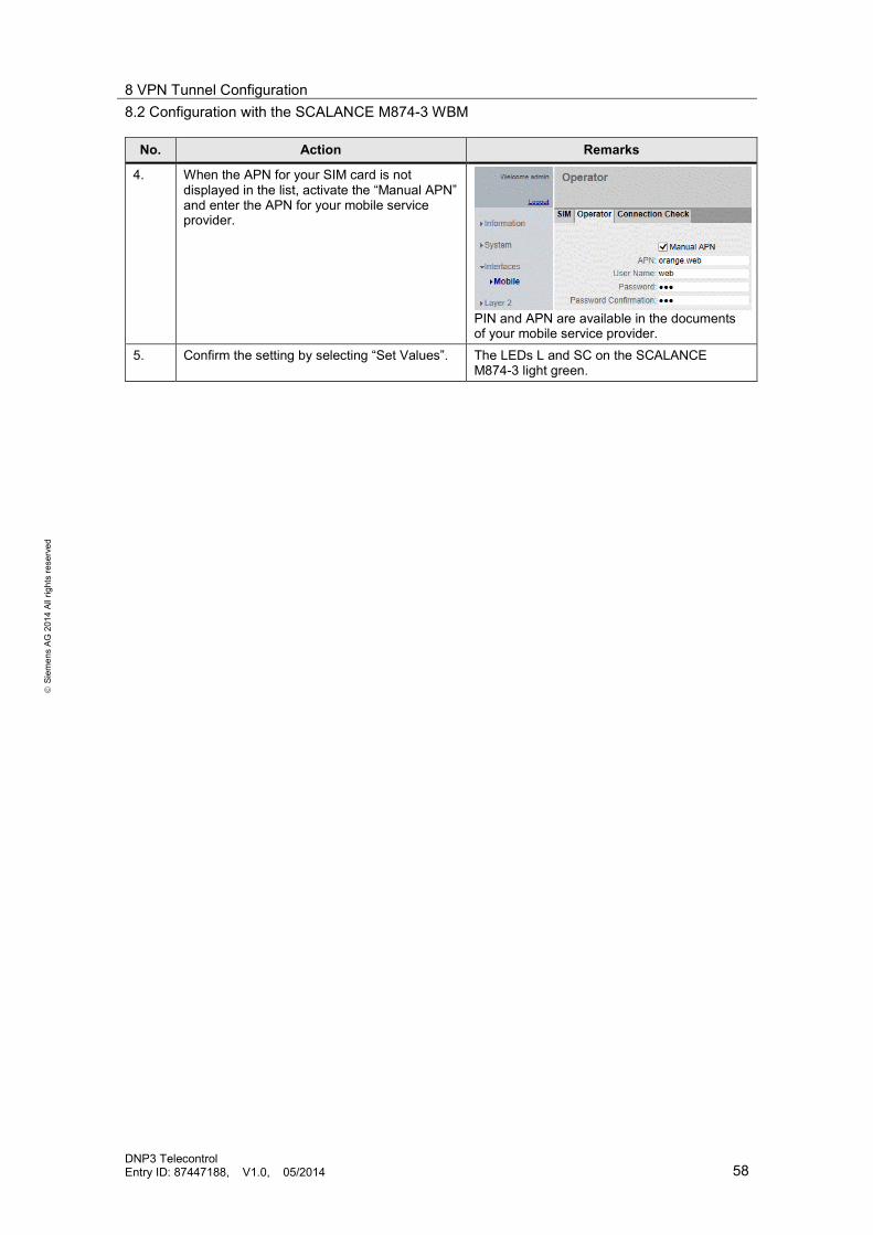
No. Action Remarks
4. When the APN for your SIM card is not displayed in the list, activate the “Manual APN” and enter the APN for your mobile service provider.
PIN and APN are available in the documents of your mobile service provider.
5. Confirm the setting by selecting “Set Values”. The LEDs L and SC on the SCALANCE M874-3 light green.

8 VPN Tunnel Configuration 8.2 Configuration with the SCALANCE M874-3 WBM
DNP3 Telecontrol Entry ID: 87447188, V1.0, 05/2014 59
S
iem
ens
AG 2
014
All r
ight
s re
serv
ed
8.2.3 Configuring the IP address
Table 8-7
No. Action Remarks
1. Go to “System > Agent IP”. 2. Enter a new IP address for the SCALANCE M
of the S7-300 station. (See Table 8-1). Confirm the setting by selecting “Set Values”.
3. Set the IP address of the PG/PC to
192.168.0.100. (see Remarks) The IP address of the PG/PC must be located in the same network as the default IP address of the SCALANCE M874-3.
4. Enter the new IP address of the SCALANCE M in your browser and log on to the WBM.
8.2.4 Set system time
Table 8-8
No. Action Remarks
1. Go to “System > System time”. 2. Click on “Use PC time” and acknowledge the
settings with “Set Values”.
3. Go to the “NTP Client” tab.
Activate the “NTP Client” checkbox to activate the automatic time synchronization via NTP. (see picture in step 8)
4. In the “Time Zone” field you specify your used time in the format "+/- HH:MM".
The time zone refers to UTC standard world time. Settings for summer or winter time are taken into account when you specify the time offset in this field.
5. Enter the IP address of the NTP server. 6. Enter the port of the NTP server. 7. Here you enter the time interval between two time requests. In this field you specify the poll
interval in seconds.
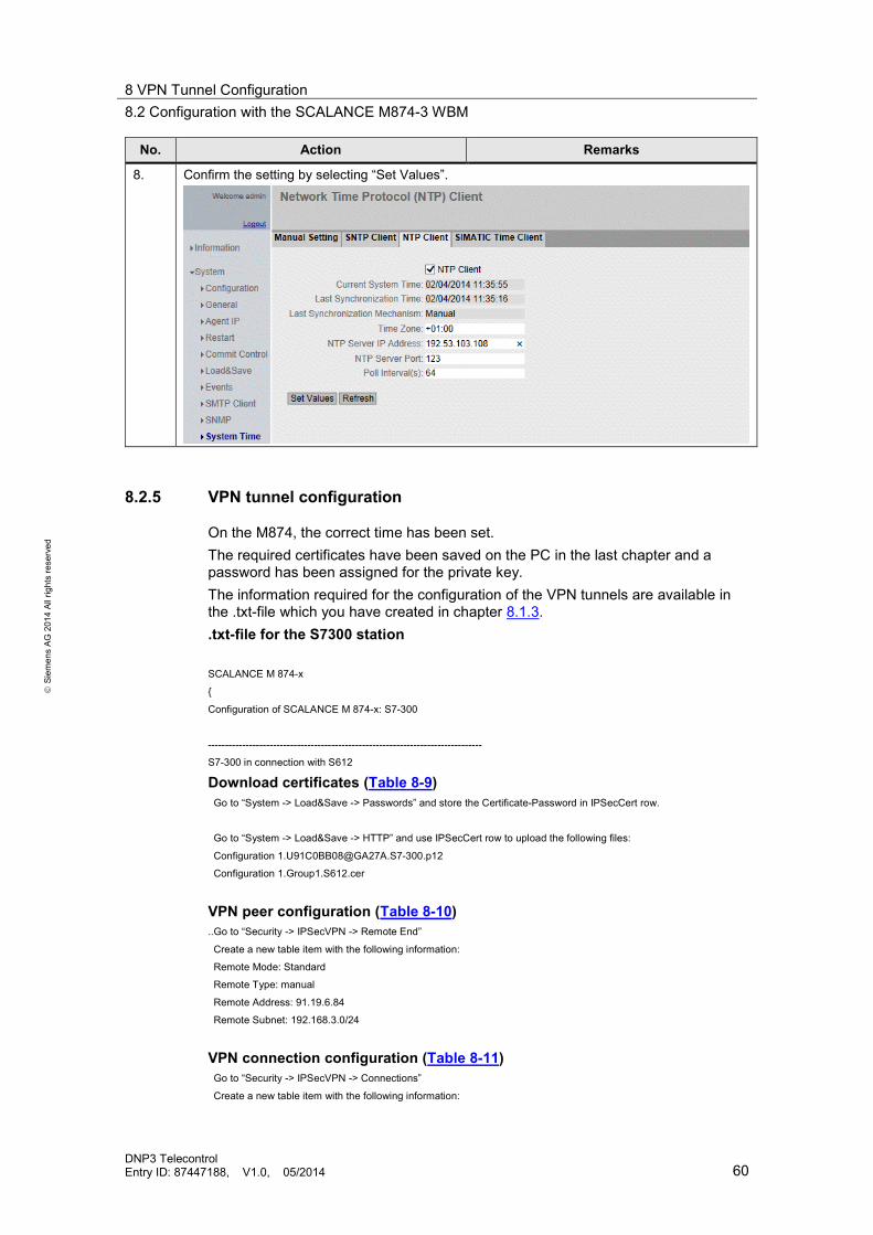
8 VPN Tunnel Configuration 8.2 Configuration with the SCALANCE M874-3 WBM
DNP3 Telecontrol Entry ID: 87447188, V1.0, 05/2014 60
S
iem
ens
AG 2
014
All r
ight
s re
serv
ed
No. Action Remarks
8. Confirm the setting by selecting “Set Values”.
8.2.5 VPN tunnel configuration
On the M874, the correct time has been set. The required certificates have been saved on the PC in the last chapter and a password has been assigned for the private key. The information required for the configuration of the VPN tunnels are available in the .txt-file which you have created in chapter 8.1.3. .txt-file for the S7300 station SCALANCE M 874-x
{
Configuration of SCALANCE M 874-x: S7-300
--------------------------------------------------------------------------------
S7-300 in connection with S612
Download certificates (Table 8-9) Go to “System -> Load&Save -> Passwords” and store the Certificate-Password in IPSecCert row.
Go to “System -> Load&Save -> HTTP” and use IPSecCert row to upload the following files:
Configuration [email protected]
Configuration 1.Group1.S612.cer
VPN peer configuration (Table 8-10) ..Go to “Security -> IPSecVPN -> Remote End”
Create a new table item with the following information:
Remote Mode: Standard
Remote Type: manual
Remote Address: 91.19.6.84
Remote Subnet: 192.168.3.0/24
VPN connection configuration (Table 8-11) Go to “Security -> IPSecVPN -> Connections”
Create a new table item with the following information:

8 VPN Tunnel Configuration 8.2 Configuration with the SCALANCE M874-3 WBM
DNP3 Telecontrol Entry ID: 87447188, V1.0, 05/2014 61
S
iem
ens
AG 2
014
All r
ight
s re
serv
ed
Keying Protocol: IKEv1
Remote End: choose the Remote End you created
Local Subnet: 192.168.0.0/24
VPN authentication configuration (Table 8-12)
Go to “Security -> IPSecVPN -> Authentication”
Set for your connection the following values:
Authentication: Remote Cert
Local Certificate: Configuration [email protected]_Cert.pem
Local ID: U91C0BB08@GA27A
Remote Certificate: Configuration 1.Group1.S612.cer
Remote ID: UF58CB8E6@GA27A
Phase 1 and phase 2 configuration (Table 8-13) Go to “Security -> IPSecVPN -> Phase 1”
Encryption: 3DES168
Authentication: SHA1
DH-Group: Group2
Keying Tries: 0 (=infinite)
Lifetime [min]: 1440
DPD: restart
DPD Delay [sec]: default
DPD Timeout [sec]: default
Aggressive Mode: No
Go to “Security -> IPSecVPN -> Phase 2”
Encryption: 3DES168
Authentication: SHA1
Lifetime [min]: 1440
Lifebytes: 0
Establish and activate VPN connection (Table 8-14) Go to “Security -> IPSecVPN -> Connections”
Operation: start
Go to “Security -> IPSecVPN -> General”
Check “Activate IPSec VPN”
}
Download certificates Table 8-9
No. Action Remarks
1. Open the .txt-file which you have created for the S7-300 station in chapter 8.1.3. 2. Go to “System > Load & Save” and switch to the “Passwords” tab.
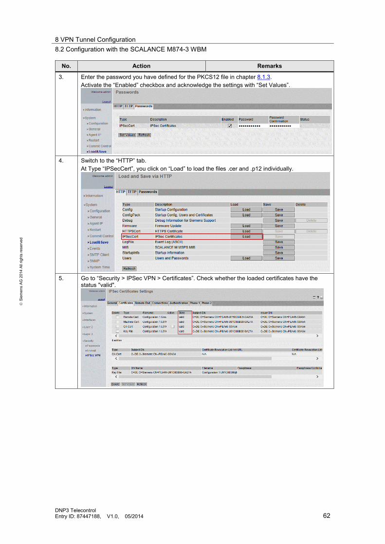
8 VPN Tunnel Configuration 8.2 Configuration with the SCALANCE M874-3 WBM
DNP3 Telecontrol Entry ID: 87447188, V1.0, 05/2014 62
S
iem
ens
AG 2
014
All r
ight
s re
serv
ed
No. Action Remarks
3. Enter the password you have defined for the PKCS12 file in chapter 8.1.3. Activate the “Enabled” checkbox and acknowledge the settings with “Set Values”.
4. Switch to the “HTTP” tab.
At Type “IPSecCert”, you click on “Load” to load the files .cer and .p12 individually.
5. Go to “Security > IPSec VPN > Certificates”. Check whether the loaded certificates have the
status "valid".

8 VPN Tunnel Configuration 8.2 Configuration with the SCALANCE M874-3 WBM
DNP3 Telecontrol Entry ID: 87447188, V1.0, 05/2014 63
S
iem
ens
AG 2
014
All r
ight
s re
serv
ed
VPN peer configuration Table 8-10
No. Action Remarks
1. Go to the “Remote End” tab. 2. Assign a name for the VPN peer, e.g. S612 and acknowledge with “Create”.
3. Enter the data of the .txt-file (section VPN peer configuration), as in the picture.
Confirm the setting by selecting “Set Values”.
VPN connection configuration Table 8-11
No. Action Remarks
1. Switch to the “Connections” tab. 2. Assign a name for the VPN connection and acknowledge with “Create”. 3. Configure the VPN connection using the data of the .txt-file (section VPN connection
configuration), as in the picture. In the “Remote End” field you select the VPN peer you have created in Table 8-10.
Confirm the setting by selecting “Set Values”.

8 VPN Tunnel Configuration 8.2 Configuration with the SCALANCE M874-3 WBM
DNP3 Telecontrol Entry ID: 87447188, V1.0, 05/2014 64
S
iem
ens
AG 2
014
All r
ight
s re
serv
ed
VPN authentication configuration Table 8-12
No. Action Remarks
1. Go to the “Authentication” tab. 2. Select “Remote Cert” option in the “Authentication” field. (see picture in step no.5) 3. In the “Local Certificate” field and the “Remote Certificate” field you select the certificates which
are offered for selection. (You have loaded these certificates in Table 8-9) 4. Copy the “Remote ID” from the .txt-file (section VPN authentication configuration) and enter it in
the respective field. 5. Confirm the setting by selecting “Set Values”.
Phase 1 and phase 2 configuration Table 8-13
No. Action Remarks
1. Switch to the “Phase 1” tab.
2. Configure phase 1 using the data of the .txt-file (section Phase 1 and phase 2 configuration), as
in the picture.
Confirm the setting by selecting “Set Values”.
3. Switch to the “Phase 2” tab. Configure phase 2 using the data of the .txt-file, as in the picture.
Confirm the setting by selecting “Set Values”.
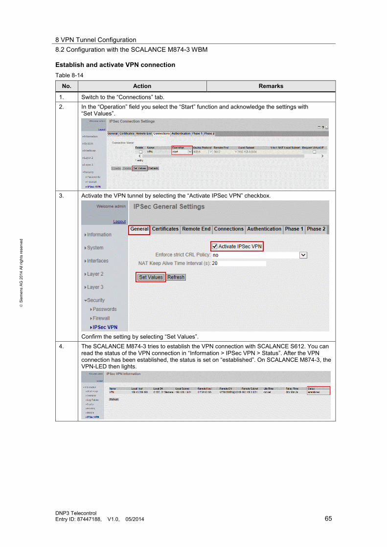
8 VPN Tunnel Configuration 8.2 Configuration with the SCALANCE M874-3 WBM
DNP3 Telecontrol Entry ID: 87447188, V1.0, 05/2014 65
S
iem
ens
AG 2
014
All r
ight
s re
serv
ed
Establish and activate VPN connection Table 8-14
No. Action Remarks
1. Switch to the “Connections” tab. 2. In the “Operation” field you select the “Start” function and acknowledge the settings with
“Set Values”.
3. Activate the VPN tunnel by selecting the “Activate IPSec VPN” checkbox.
Confirm the setting by selecting “Set Values”.
4. The SCALANCE M874-3 tries to establish the VPN connection with SCALANCE S612. You can read the status of the VPN connection in “Information > IPSec VPN > Status”. After the VPN connection has been established, the status is set on “established”. On SCALANCE M874-3, the VPN-LED then lights.

8 VPN Tunnel Configuration 8.2 Configuration with the SCALANCE M874-3 WBM
DNP3 Telecontrol Entry ID: 87447188, V1.0, 05/2014 66
S
iem
ens
AG 2
014
All r
ight
s re
serv
ed
8.2.6 Configuring the SCALANCE M874-3 for the S7-1200 station
For the S7-1200 station there is the option of sending alarms via e-mail. In order to be able to send the alarms, the data traffic from the internal network of SCALANCE M874-3 to the network must be allowed. This setting is made in the WBM of SCALANCE M874-3.
Table 8-15
No. Action Remarks
1. Configure the SCALANCE M874-3 for the S7-1200 station, as described in chapter 8.2:
Hence, the APN, the IP address, the system time and the VPN tunnel have been configured.
2. Go to “Security > Firewall > Predefined IPv4”. Select the “Allow IP Traffic” checkbox in the “From Internal to External” field.
3. Confirm the setting by selecting “Set Values”.

9 Installation 9.1 Installation of the hardware
DNP3 Telecontrol Entry ID: 87447188, V1.0, 05/2014 67
S
iem
ens
AG 2
014
All r
ight
s re
serv
ed
9 Installation This chapter offers installation information for hardware and software which is necessary for commissioning this application example.
9.1 Installation of the hardware
The hardware components are available in chapter 2.2. For setting up the hardware, please proceed according to the following table:
Table 9-1
No. Action Remarks
1. Insert the individual modules in a suitable rack. 2. Insert the MMC card into the respective slot of
the S7-300 S7_ CPU. An MC card is not necessary for the S7-1200.
3. Then connect the components to a 24 V DC supply (PS307). Connect the PS307 to the power grid (230 V AC).
Take note of correct polarity.
4. Connect the antenna to the respective socket of the SCALANCE M874-3.
This step is only relevant for “Configuration via Internet/VPN”.
5. Connect the TIM and the S7-300 CPU to the power supply.
6. Connect the S7-1200 to the power supply. The CP is supplied via the CPU. 7. Connect the SCALANCE X005 to the power
supply. This step is only relevant for “Configuration via Internet/VPN”.
8. After all stations have been configured and loaded, you connect the devices as in Figure 2-1 or Figure 2-2, depending on the configuration.
Note Before you switch on the power supply, complete and check the installation!
Note The installation guidelines for the installation of all components always have to be observed.
9 Installation 9.2 Installation of the software
DNP3 Telecontrol Entry ID: 87447188, V1.0, 05/2014 68
S
iem
ens
AG 2
014
All r
ight
s re
serv
ed
9.2 Installation of the software
In this application example, the configuration computer is also used as the DNP3 master at the same time. When using separate computers for the configuration and for the DNP3 master, then the following software needs to be installed on the DNP3 master computer: • SIMATIC WinCC Server Runtime V7.0 SP3 • SIMATIC TeleControl 7.0 SP3 for WinCC Server Runtime
Order of installation Install the software listed in Table 2-2. Pay attention to the following installation order. • The installation of SINAUT ST7 Engineering is only possible if STEP 7 V5.5
has been installed. • The installation of WinCC TeleControl is only possible if SIMATIC WinCC has
already been installed.
Note Please pay attention to the notes on software installation in the manuals for the respective software. (See link in chapter 12).
9.3 Installation of the application software
The following table shows all steps required for the installation of the sample code. Table 9-2
No. Action
1. The example code is available on the HTML page from which you downloaded this document. Save the "87447188_DNP3_Telecontrol_S7-300_S7-1200_v10.zip" code to your hard disk.
2. Extract the projects by right-clicking on the zipped folder.

10 Commissioning 10.1 Loading the stations
DNP3 Telecontrol Entry ID: 87447188, V1.0, 05/2014 69
S
iem
ens
AG 2
014
All r
ight
s re
serv
ed
10 Commissioning 10.1 Loading the stations
Load the configurations to the stations as described in the following subchapters. In this description, the IP addresses for the “Configuration via LAN” were used (see Table 4-1).
10.1.1 Loading the S7-300 station
Table 10-1
No. Action Remarks
1. Set the IP address of the PG/PC to 192.168.0.100, for example. (see Remarks)
The IP address of the PG/PC must be located in the same network as the IP address of the TIM.
2. Connect the PG/PC and the TIM to the SCALANCE X005 Switch. 3. Open the STEP 7 V5.5 project and go to “PLC
> Edit Ethernet Node” to set the online IP address of the TIM.
4. Click on the “Browse” button.
5. Select the TIM module. Confirm your selection
by clicking on OK.

10 Commissioning 10.1 Loading the stations
DNP3 Telecontrol Entry ID: 87447188, V1.0, 05/2014 70
S
iem
ens
AG 2
014
All r
ight
s re
serv
ed
No. Action Remarks
6. Enter the IP address for the TIM as configured in the project. IP address:192.168.0.101 255.255.255.0 Click on the “Assign IP Configuration” button.
7. Now you can load the project to the S7-300
station. Select the station and click on the “Download” icon.
10.1.2 Loading the S7-1200 station
Table 10-2
No. Action Remarks
1. Set the IP address of the PG/PC to 192.168.0.100, for example. (see Remarks)
The IP address of the PG/PC must be located in the same network as the IP address of the CPU.
2. Connect the PG/PC and the S7-1200 CPU to the SCALANCE X005 Switch.
Since in the factory settings of the CP, communication type “Teleservice” is deactivated, the STEP 7 project cannot yet be loaded to the CPU via the CP. In the application project, this function is activated; i.e., after the project has been loaded to your CPU, you can also load the program changes to the CPU via the CP.
3. In TIA Portal you open the STEP 7 V12 project in the TIA portal.
4. In the "Project tree", go to: “Online access > Adapter card for the network in which the device is located > Update accessible devices”
5. In the required accessible device you double-
click on the “Online & diagnostics” object.

10 Commissioning 10.2 Configuration for the communication via VPN tunnel
DNP3 Telecontrol Entry ID: 87447188, V1.0, 05/2014 71
S
iem
ens
AG 2
014
All r
ight
s re
serv
ed
No. Action Remarks
6. In the "Online & diagnostics" dialog, go to “Functions > Assign IP address”.
7. Enter the IP address in accordance with the
project settings and click on “Assign IP address”.
8. Select the S7 station and download the CPU
project to your S7-CPU via the download icon.
9. Remove the Ethernet cable from the CPU and
instead, connect the CP to the SCALANCE X005 Switch.
10.2 Configuration for the communication via VPN tunnel If you wish to commission the “Configuration via Internet/VPN”, make the following changes in the supplied code.
10.2.1 Configuring the e-mail address (S7-1200)
Table 10-3
No. Action Remarks
1. Make the settings for the SMTP server as described in step 3, chapter 6.3. 2. Enter the e-mail address of the receiver as described in step 6, chapter 6.3.
Note When not using the IP address for the SCALANCE M874-3 described in this application, make the settings for the DNS server as in step 2, chapter 6.3.

10 Commissioning 10.2 Configuration for the communication via VPN tunnel
DNP3 Telecontrol Entry ID: 87447188, V1.0, 05/2014 72
S
iem
ens
AG 2
014
All r
ight
s re
serv
ed
10.2.2 Adjusting the IP address
STEP 7 project and SINAUT project Table 10-4
No. Action Remarks
1. Retrieve the application project DNP_S7-300 with the SIMATIC Manager. 2. Open the TIM properties as described in chapter 5.1. 3. Set the IP address of TIM via “Properties”.
Enter the LAN IP address of the SCALANCE M874-3 as the router. (e.g. 192.168.0.10)
4. In order for the S7-300 station to communicate
with the DNP3 master, it must know the IP address of the master. Double-click on the DNP3 master.
5. Go to the “Interfaces” tab and double-click on
the Ethernet interface.
6. Enter the IP address for the DNP3 master.
Enter the IP address of the SCALANCE S612 as the router. (e.g. 192.168.3.1)

10 Commissioning 10.2 Configuration for the communication via VPN tunnel
DNP3 Telecontrol Entry ID: 87447188, V1.0, 05/2014 73
S
iem
ens
AG 2
014
All r
ight
s re
serv
ed
No. Action Remarks
7. Compile the project.
8. Start the SINAUT ST7 configuration tool via:
“Start > all programs > Siemens Automation > SIMATIC > SINAUT ST7 > SINAUT ST7configuration”
9. Open the STEP 7 project. 10. Select “Subscriber Administration” and start
with OK.
11. Save the project.
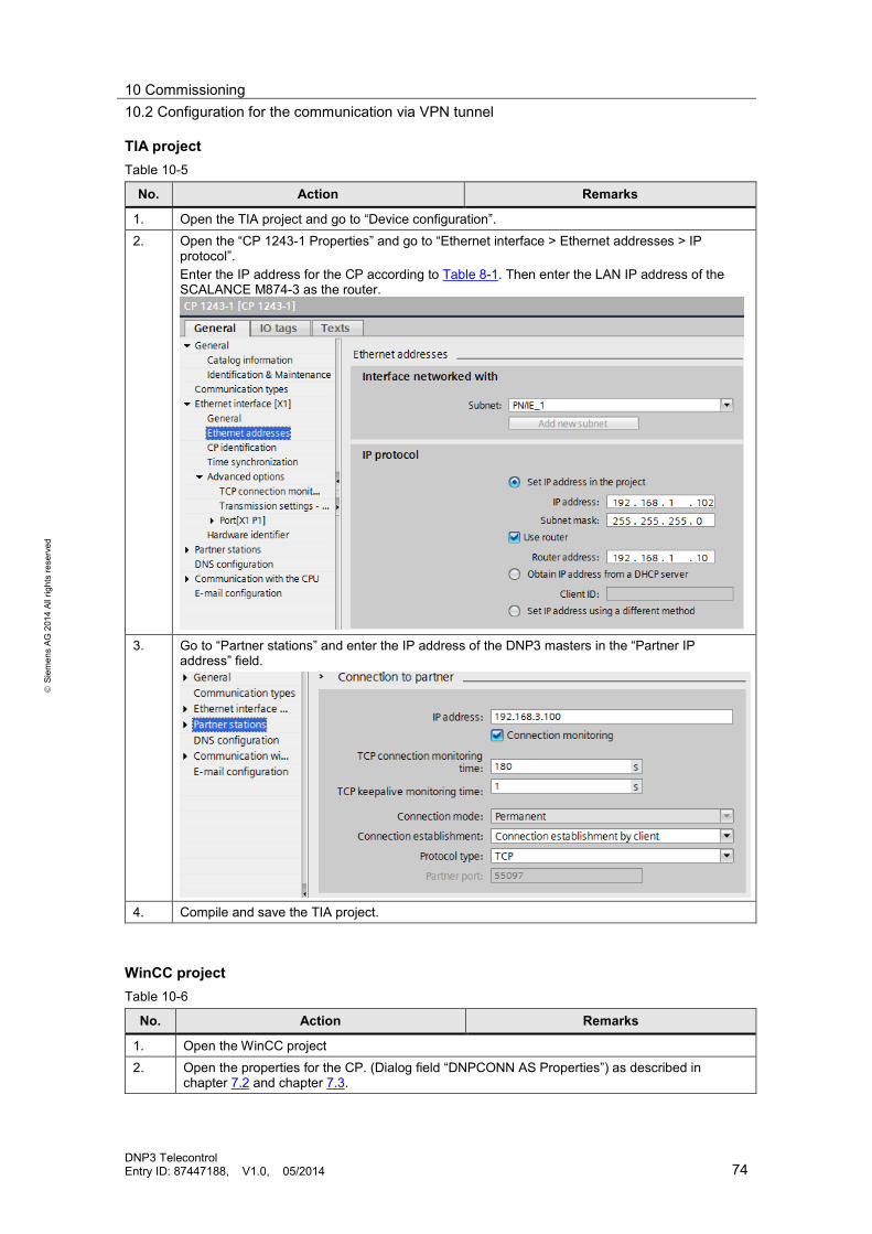
10 Commissioning 10.2 Configuration for the communication via VPN tunnel
DNP3 Telecontrol Entry ID: 87447188, V1.0, 05/2014 74
S
iem
ens
AG 2
014
All r
ight
s re
serv
ed
TIA project Table 10-5
No. Action Remarks
1. Open the TIA project and go to “Device configuration”. 2. Open the “CP 1243-1 Properties” and go to “Ethernet interface > Ethernet addresses > IP
protocol”. Enter the IP address for the CP according to Table 8-1. Then enter the LAN IP address of the SCALANCE M874-3 as the router.
3. Go to “Partner stations” and enter the IP address of the DNP3 masters in the “Partner IP
address” field.
4. Compile and save the TIA project.
WinCC project Table 10-6
No. Action Remarks
1. Open the WinCC project 2. Open the properties for the CP. (Dialog field “DNPCONN AS Properties”) as described in
chapter 7.2 and chapter 7.3.

10 Commissioning 10.2 Configuration for the communication via VPN tunnel
DNP3 Telecontrol Entry ID: 87447188, V1.0, 05/2014 75
S
iem
ens
AG 2
014
All r
ight
s re
serv
ed
No. Action Remarks
3. Enter the IP address of the CP.
4. Repeat the process for the TIM, if necessary.
Note Download the stations as described in chapter 10.1.
Assigning the IP address of the PG/PC After you have loaded all stations, assign the IP address to the PG as described in the following table.
Table 10-7
No. Action Remarks
1. Set the IP address according to Table 8-1, Enter the internal IP address of the SCALANCE S612 as the “Default gateway”. In the “Preferred DNS server” field you enter the internal IP address of the DSL router.

10 Commissioning 10.2 Configuration for the communication via VPN tunnel
DNP3 Telecontrol Entry ID: 87447188, V1.0, 05/2014 76
S
iem
ens
AG 2
014
All r
ight
s re
serv
ed
10.2.3 VPN tunnel configuration
Configure the VPN tunnel as described in chapter 8. Alternatively, you can adjust the supplied SCT and SCALANCE M projects. However, when using different IP addresses or more wish to make more changes, it is recommended to recreate the projects.
Commissioning the SCT project Table 10-8
No. Action Remarks
1. Open the “DNP3_SCT” project with the Security Configuration Tool (SCT) via: “Start > “All programs” > SIEMENS Automation > SIMATIC > Security > Security Configuration Tool”.
User name: DNP3 Password: SINAUT&M874-3
2. Enter the MAC address for the SCALANCE S612 in the module line. (The MAC address is printed on the front of the SCALANCE S.)
3. Double-click on the S612. 4. The window with the properties of the SCALANCE S612 opens.
Go to the VPN tab and enter the fixed IP address (or the domain name) of your DSL routers in the “WAN IP address/FQDN” field.
5. Click on OK to confirm the settings. 6. Download the configuration as described in chapter 8.1.3.
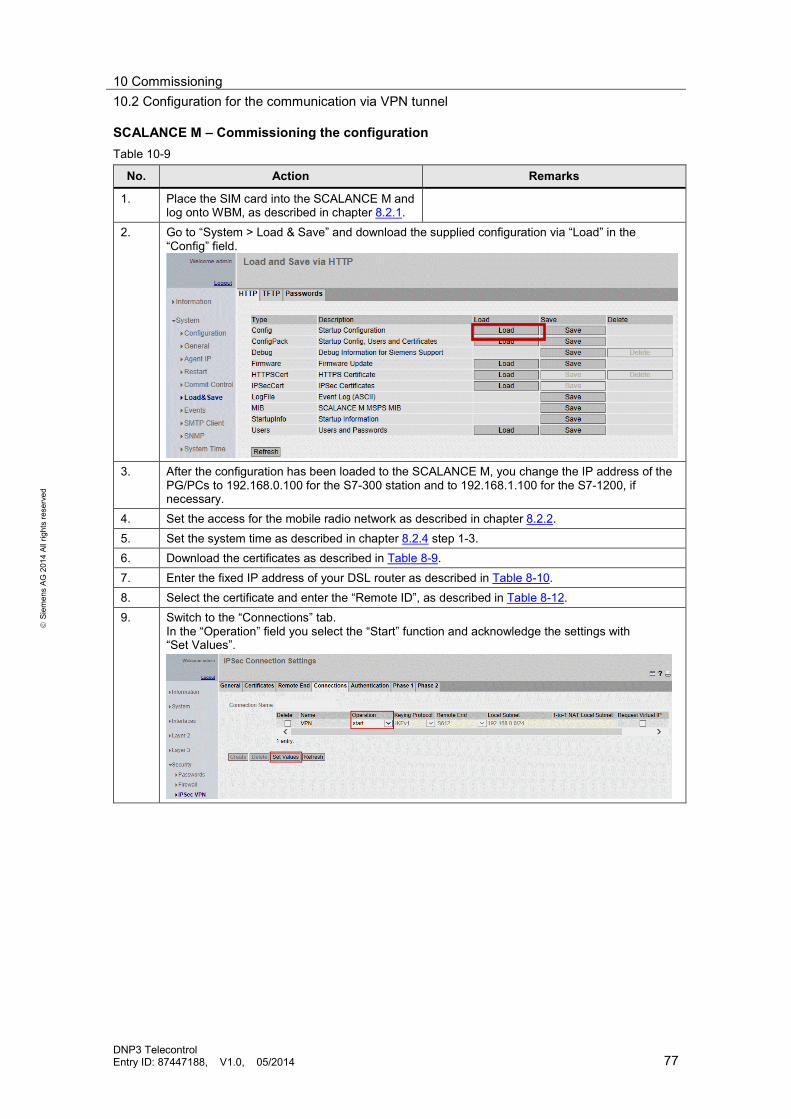
10 Commissioning 10.2 Configuration for the communication via VPN tunnel
DNP3 Telecontrol Entry ID: 87447188, V1.0, 05/2014 77
S
iem
ens
AG 2
014
All r
ight
s re
serv
ed
SCALANCE M – Commissioning the configuration Table 10-9
No. Action Remarks
1. Place the SIM card into the SCALANCE M and log onto WBM, as described in chapter 8.2.1.
2. Go to “System > Load & Save” and download the supplied configuration via “Load” in the “Config” field.
3. After the configuration has been loaded to the SCALANCE M, you change the IP address of the
PG/PCs to 192.168.0.100 for the S7-300 station and to 192.168.1.100 for the S7-1200, if necessary.
4. Set the access for the mobile radio network as described in chapter 8.2.2. 5. Set the system time as described in chapter 8.2.4 step 1-3. 6. Download the certificates as described in Table 8-9. 7. Enter the fixed IP address of your DSL router as described in Table 8-10. 8. Select the certificate and enter the “Remote ID”, as described in Table 8-12. 9. Switch to the “Connections” tab.
In the “Operation” field you select the “Start” function and acknowledge the settings with “Set Values”.

11 Operation of the Application 11.1 Overview
DNP3 Telecontrol Entry ID: 87447188, V1.0, 05/2014 78
S
iem
ens
AG 2
014
All r
ight
s re
serv
ed
11 Operation of the Application 11.1 Overview
As soon as the stations have been configured and downloaded, the application can be operated by starting WinCC Runtime. The S7-300 is operated independently of the S7-1200. This subchapter gives you an overview of the operating parameters which have the same name for both stations.
Figure 11-1
Table 11-1
No. Action Remarks
1. Start the demo via the Toggler button “START Demo”. If the Demo has been started, the “STOP Demo” button is displayed, which enables terminating the demonstration.
2. You can trigger a general request via the “General Request GR_ALL” button. During the DNP3 configuration, there is also the option of defining certain polling groups for the request.
3. The “GR Status GS” display gives information on the status of the general request.
This parameter can take on the following values: 1=GA Start requested 2=GA runs 3=GA error 4= GA terminated OK 5= GA termination incomplete
1 1 2 2
3 3
4 4
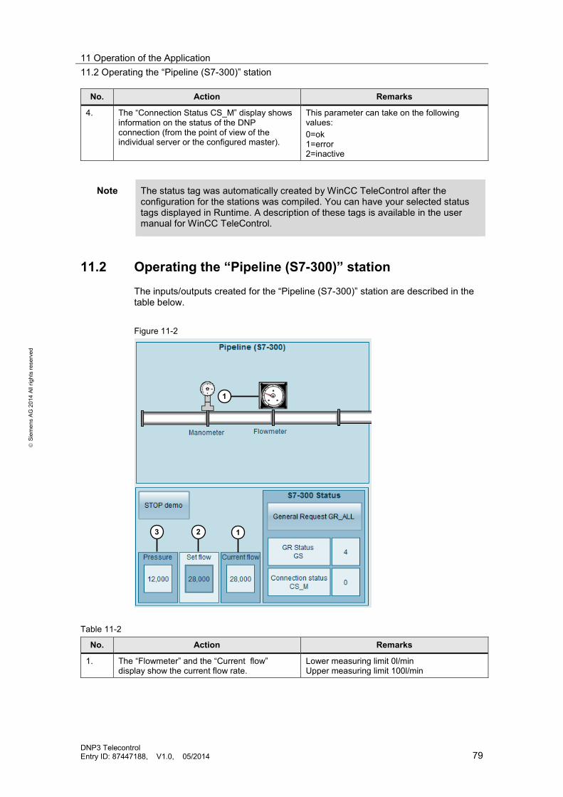
11 Operation of the Application 11.2 Operating the “Pipeline (S7-300)” station
DNP3 Telecontrol Entry ID: 87447188, V1.0, 05/2014 79
S
iem
ens
AG 2
014
All r
ight
s re
serv
ed
No. Action Remarks
4. The “Connection Status CS_M” display shows information on the status of the DNP connection (from the point of view of the individual server or the configured master).
This parameter can take on the following values: 0=ok 1=error 2=inactive
Note The status tag was automatically created by WinCC TeleControl after the configuration for the stations was compiled. You can have your selected status tags displayed in Runtime. A description of these tags is available in the user manual for WinCC TeleControl.
11.2 Operating the “Pipeline (S7-300)” station The inputs/outputs created for the “Pipeline (S7-300)” station are described in the table below. Figure 11-2
Table 11-2
No. Action Remarks
1. The “Flowmeter” and the “Current flow” display show the current flow rate.
Lower measuring limit 0l/min Upper measuring limit 100l/min
1
3 2 1
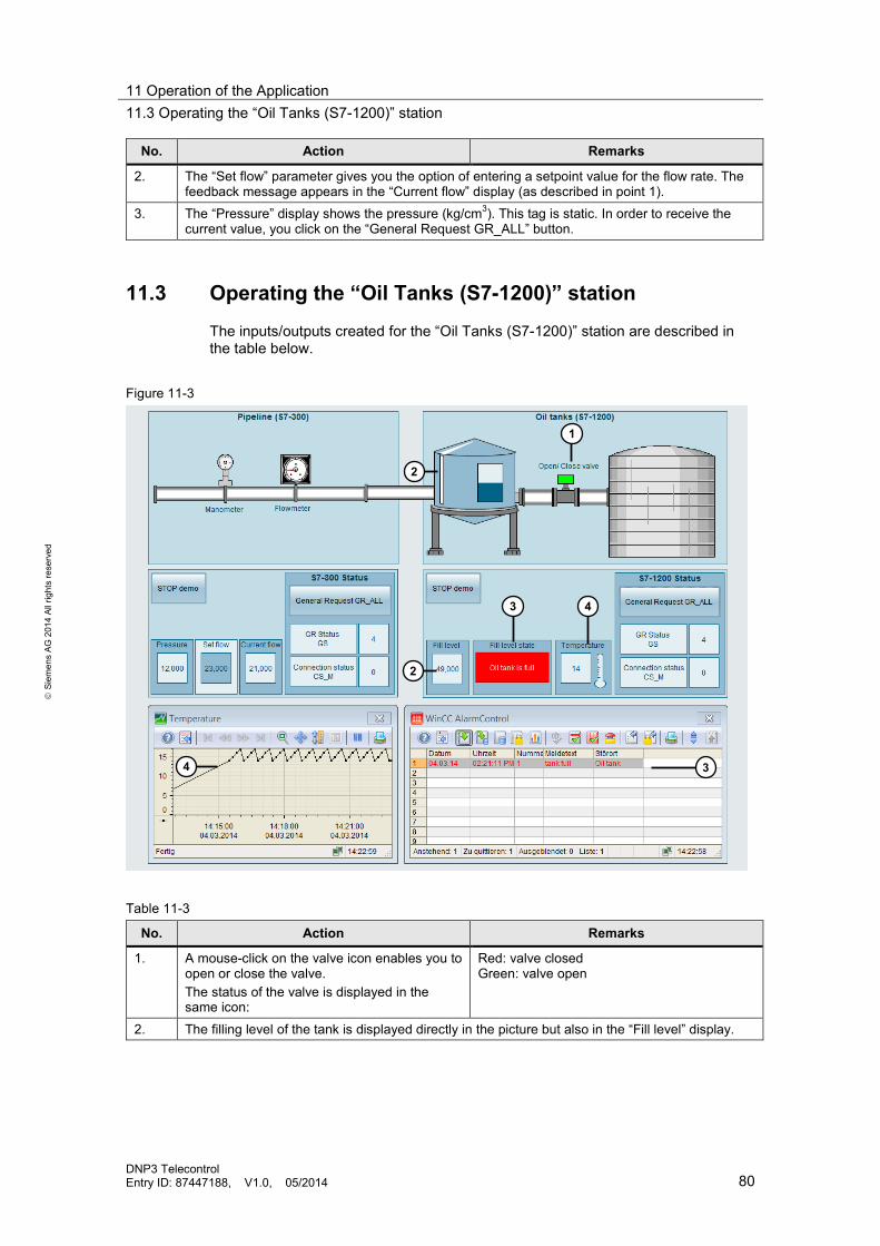
11 Operation of the Application 11.3 Operating the “Oil Tanks (S7-1200)” station
DNP3 Telecontrol Entry ID: 87447188, V1.0, 05/2014 80
S
iem
ens
AG 2
014
All r
ight
s re
serv
ed
No. Action Remarks
2. The “Set flow” parameter gives you the option of entering a setpoint value for the flow rate. The feedback message appears in the “Current flow” display (as described in point 1).
3. The “Pressure” display shows the pressure (kg/cm3). This tag is static. In order to receive the current value, you click on the “General Request GR_ALL” button.
11.3 Operating the “Oil Tanks (S7-1200)” station The inputs/outputs created for the “Oil Tanks (S7-1200)” station are described in the table below.
Figure 11-3
Table 11-3
No. Action Remarks
1. A mouse-click on the valve icon enables you to open or close the valve. The status of the valve is displayed in the same icon:
Red: valve closed Green: valve open
2. The filling level of the tank is displayed directly in the picture but also in the “Fill level” display.
1
2
2
3 4
3 4

11 Operation of the Application 11.3 Operating the “Oil Tanks (S7-1200)” station
DNP3 Telecontrol Entry ID: 87447188, V1.0, 05/2014 81
S
iem
ens
AG 2
014
All r
ight
s re
serv
ed
No. Action Remarks
3. The status of filling level is displayed at “fill level state”. If the filling level exceeds the value 80, the status is reset to “Oil tank is full”. At the same time, this status is displayed as alarm in WinCC Alarm Control.
Status:
• OK • Oil tank is full
4. The temperature is a class 2 tag which is only sent after a request by the master. Old values are saved in the CPU and, after the request by the master, sent together with the current value. The temperature value is displayed at “Temperature”. The temperature is also displayed as a trend, where old values can also be read.
Note When the “fill_level_alram” tag is set in the CPU, an alarm is sent to the configured receiver as an e-mail.

12 Diagnostics 12.1 Wireshark
DNP3 Telecontrol Entry ID: 87447188, V1.0, 05/2014 82
S
iem
ens
AG 2
014
All r
ight
s re
serv
ed
12 Diagnostics This chapter describes the options for diagnosing the communication between master and station and the data traffic.
12.1 Wireshark
The Wireshark freeware is used for writing all IP message frames. Table 12-1
No. Action Remarks
1. Click on “Capture” to start the recording. Press the “Stop” button to terminate the recording. Enter the “dnp3” text as a filter, if you only wish to analyze the DNP3 message frames. For each frame, the IP address of the source and the target is available as well as the type of frame. The message frame selected here is a response to a request from the master, sent by DNP3 address 2. The bottom window pane displays the data of the frame, for example: group, variation, value of the object, etc.

12 Diagnostics 12.2 SINAUT Diagnostics and Service tool
DNP3 Telecontrol Entry ID: 87447188, V1.0, 05/2014 83
S
iem
ens
AG 2
014
All r
ight
s re
serv
ed
12.2 SINAUT Diagnostics and Service tool
The SINAUT Diagnostics and Service tool is only suitable for diagnosing the stations which were configured via the SINAUT Configuration tool.
Module information Table 12-2
No. Action Remarks
1. Open your project with the SINAUT Diagnostics and Service tool. 2. Right-click on the TIM module and then select “Module information”.
3. The window with the module information
opens. In this window, messages for DNP3 are displayed in addition to the standard SIMATIC diagnostic information. Note: this diagnostic window is also available for STEP 7.

12 Diagnostics 12.2 SINAUT Diagnostics and Service tool
DNP3 Telecontrol Entry ID: 87447188, V1.0, 05/2014 84
S
iem
ens
AG 2
014
All r
ight
s re
serv
ed
TIM subscriber diagnostics Table 12-3
No. Action Remarks
1. Right-click on the TIM module and then select “TIM> TIM subscriber diagnostics”.
2. The window with the partner of the TIM opens. Here you find information on the connection of
the TIM to the DNP3 master or to your local CPU.

12 Diagnostics 12.2 SINAUT Diagnostics and Service tool
DNP3 Telecontrol Entry ID: 87447188, V1.0, 05/2014 85
S
iem
ens
AG 2
014
All r
ight
s re
serv
ed
No. Action Remarks
3. If the connection with the partner has not been established, this partner is displayed with a red hook.
TD7onTIM diagnostics Table 12-4
No. Action Remarks
1. Right-click on the TIM module and then select “TIM> TD7onTIM diagnostics”.
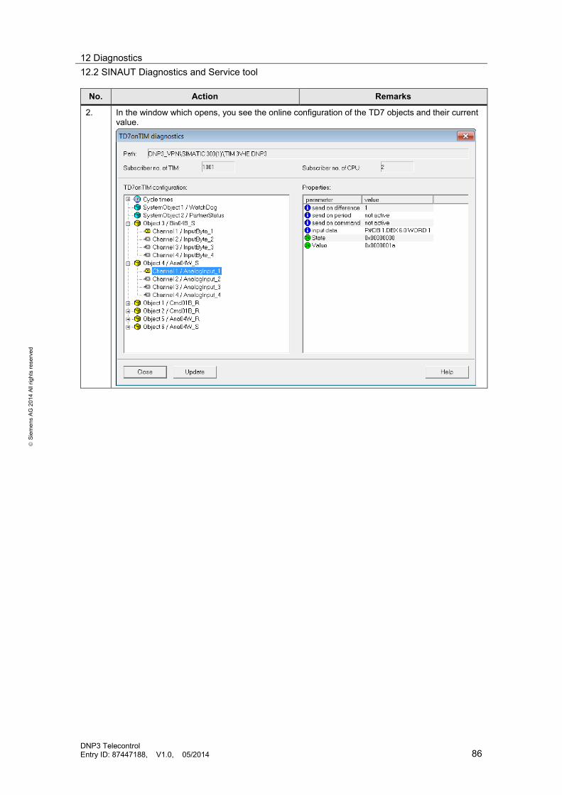
12 Diagnostics 12.2 SINAUT Diagnostics and Service tool
DNP3 Telecontrol Entry ID: 87447188, V1.0, 05/2014 86
S
iem
ens
AG 2
014
All r
ight
s re
serv
ed
No. Action Remarks
2. In the window which opens, you see the online configuration of the TD7 objects and their current value.

12 Diagnostics 12.3 TIA Portal
DNP3 Telecontrol Entry ID: 87447188, V1.0, 05/2014 87
S
iem
ens
AG 2
014
All r
ight
s re
serv
ed
12.3 TIA Portal
In this chapter, only the diagnostics options available for the CP 1243-1 DNP3 are described.
Table 12-5
No. Action Remarks
1. Open your STEP 7 V12 project and then go to “Device configuration”. 2. With the right mouse-button, you click on the
CP and select “Go online”.
3. Go to the “Partner” tab and click on “Save partner diagnostic”.
Note: the file is saved as HTML.
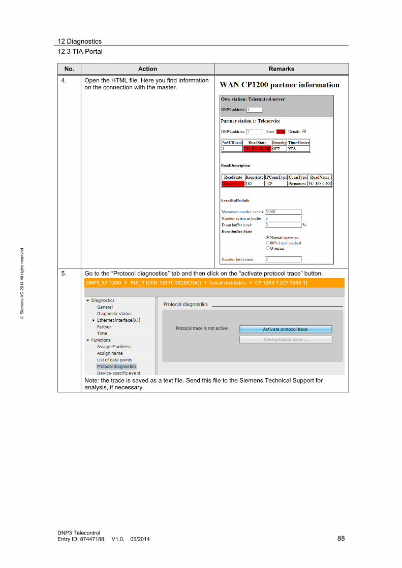
12 Diagnostics 12.3 TIA Portal
DNP3 Telecontrol Entry ID: 87447188, V1.0, 05/2014 88
S
iem
ens
AG 2
014
All r
ight
s re
serv
ed
No. Action Remarks
4. Open the HTML file. Here you find information on the connection with the master.
5. Go to the “Protocol diagnostics” tab and then click on the “activate protocol trace” button.
Note: the trace is saved as a text file. Send this file to the Siemens Technical Support for analysis, if necessary.

12 Diagnostics 12.3 TIA Portal
DNP3 Telecontrol Entry ID: 87447188, V1.0, 05/2014 89
S
iem
ens
AG 2
014
All r
ight
s re
serv
ed
No. Action Remarks
6. Go to the “List of data points” tab and then click the “save datapoint list…” button.
Note: the file is saved as HTML.
7. Open the HTML file. Information on the configured data points can be found here. You can also see the current values of the data points including time stamp.

12 Diagnostics 12.4 SMTP server diagnostics (e-mail)
DNP3 Telecontrol Entry ID: 87447188, V1.0, 05/2014 90
S
iem
ens
AG 2
014
All r
ight
s re
serv
ed
12.4 SMTP server diagnostics (e-mail)
If the configured alarm is not sent, even though the sent trigger has been set, check the value of the tag you have configured in the “External status” field (see step 7, chapter 6.3). The list of possible values and their meaning is available in the pdf-document for STEP 7 V12 “Sending e-mails to SMTP server with an S7-CPU”, link \11\.
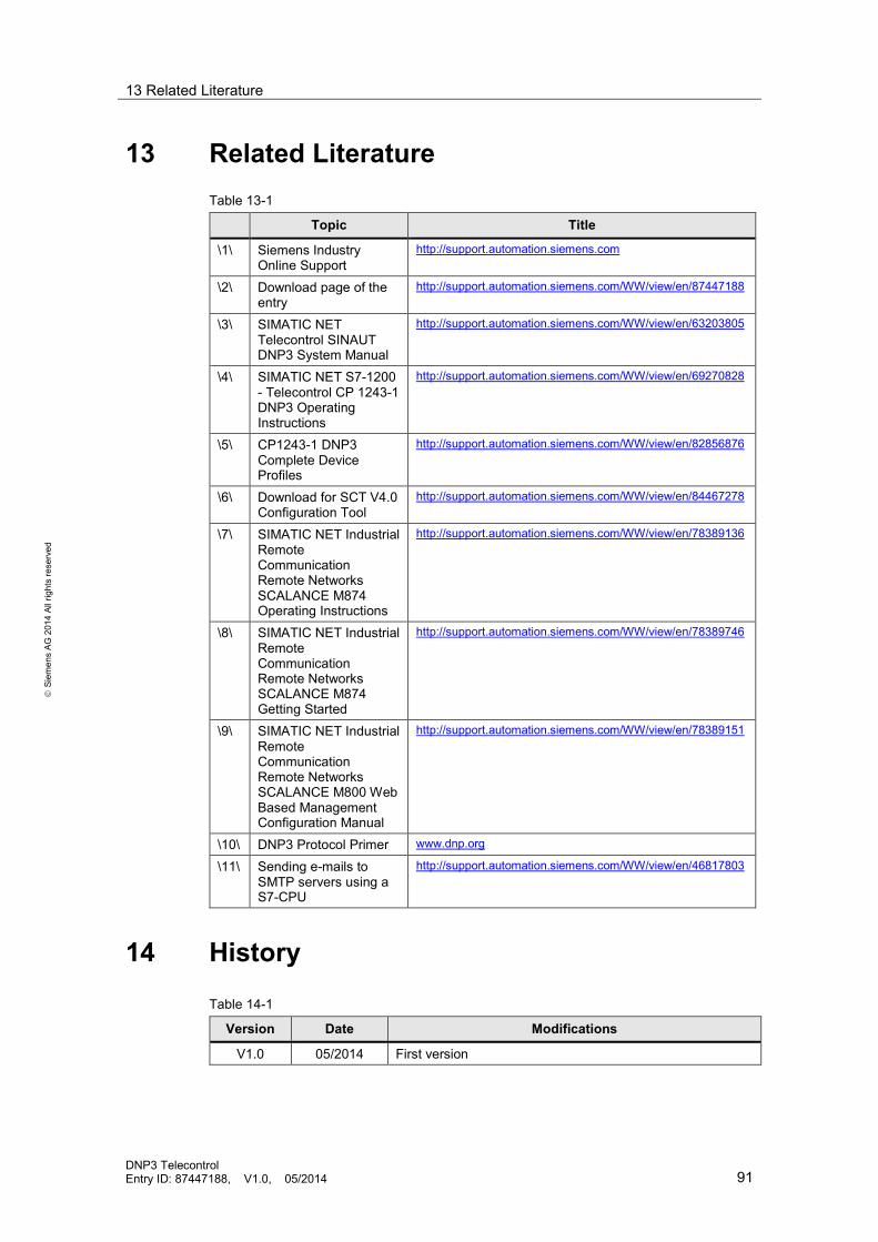
13 Related Literature
DNP3 Telecontrol Entry ID: 87447188, V1.0, 05/2014 91
S
iem
ens
AG 2
014
All r
ight
s re
serv
ed
13 Related Literature Table 13-1
Topic Title
\1\ Siemens Industry Online Support
http://support.automation.siemens.com
\2\ Download page of the entry
http://support.automation.siemens.com/WW/view/en/87447188
\3\ SIMATIC NET Telecontrol SINAUT DNP3 System Manual
http://support.automation.siemens.com/WW/view/en/63203805
\4\ SIMATIC NET S7-1200 - Telecontrol CP 1243-1 DNP3 Operating Instructions
http://support.automation.siemens.com/WW/view/en/69270828
\5\ CP1243-1 DNP3 Complete Device Profiles
http://support.automation.siemens.com/WW/view/en/82856876
\6\ Download for SCT V4.0 Configuration Tool
http://support.automation.siemens.com/WW/view/en/84467278
\7\ SIMATIC NET Industrial Remote Communication Remote Networks SCALANCE M874 Operating Instructions
http://support.automation.siemens.com/WW/view/en/78389136
\8\ SIMATIC NET Industrial Remote Communication Remote Networks SCALANCE M874 Getting Started
http://support.automation.siemens.com/WW/view/en/78389746
\9\ SIMATIC NET Industrial Remote Communication Remote Networks SCALANCE M800 Web Based Management Configuration Manual
http://support.automation.siemens.com/WW/view/en/78389151
\10\ DNP3 Protocol Primer www.dnp.org
\11\ Sending e-mails to SMTP servers using a S7-CPU
http://support.automation.siemens.com/WW/view/en/46817803
14 History Table 14-1
Version Date Modifications
V1.0 05/2014 First version