application example 03/2017 closed-loop control with pid ... · warranty and liability closed-loop...
TRANSCRIPT

https://support.industry.siemens.com/cs/ww/en/view/79047707
Application example 03/2017
Closed-Loop Control with "PID_Compact" V2.2 SIMATIC S7-1500

Warranty and liability
Closed-Loop Control with "PID_Compact" V2.2 Entry-ID: 79047707, V2.0.1, 03/2017 2
S
iem
en
s A
G 2
01
7 A
ll ri
gh
ts r
ese
rve
d
Warranty and liability
Note The Application Examples are not binding and do not claim to be complete regarding the circuits shown, equipping and any eventuality. The Application Examples do not represent customer-specific solutions. They are only intended to provide support for typical applications. You are responsible for ensuring that the described products are used correctly. These Application Examples do not relieve you of the responsibility to use safe practices in application, installation, operation and maintenance. When using these Application Examples, you recognize that we cannot be made liable for any damage/claims beyond the liability clause described. We reserve the right to make changes to these Application Examples at any time without prior notice. If there are any deviations between the recommendations provided in these Application Examples and other Siemens publications – e.g. Catalogs – the contents of the other documents have priority.
We do not accept any liability for the information contained in this document. Any claims against us – based on whatever legal reason – resulting from the use of the examples, information, programs, engineering and performance data etc., described in this Application Example shall be excluded. Such an exclusion shall not apply in the case of mandatory liability, e.g. under the German Product Liability Act (“Produkthaftungsgesetz”), in case of intent, gross negligence, or injury of life, body or health, guarantee for the quality of a product, fraudulent concealment of a deficiency or breach of a condition which goes to the root of the contract (“wesentliche Vertragspflichten”). The damages for a breach of a substantial contractual obligation are, however, limited to the foreseeable damage, typical for the type of contract, except in the event of intent or gross negligence or injury to life, body or health. The above provisions do not imply a change of the burden of proof to your detriment. Any form of duplication or distribution of these Application Examples or excerpts hereof is prohibited without the expressed consent of the Siemens AG.
Security informa-tion
Siemens provides products and solutions with industrial security functions that support the secure operation of plants, systems, machines and networks. In order to protect plants, systems, machines and networks against cyber threats, it is necessary to implement – and continuously maintain – a holistic, state-of-the-art industrial security concept. Siemens’ products and solutions only form one element of such a concept. Customer is responsible to prevent unauthorized access to its plants, systems, machines and networks. Systems, machines and components should only be connected to the enterprise network or the internet if and to the extent necessary and with appropriate security measures (e.g. use of firewalls and network segmentation) in place. Additionally, Siemens’ guidance on appropriate security measures should be taken into account. For more information about industrial security, please visit http://www.siemens.com/industrialsecurity.
Siemens’ products and solutions undergo continuous development to make them more secure. Siemens strongly recommends to apply product updates as soon as available and to always use the latest product versions. Use of product versions that are no longer supported, and failure to apply latest updates may increase customer’s exposure to cyber threats. To stay informed about product updates, subscribe to the Siemens Industrial Security RSS Feed under http://www.siemens.com/industrialsecurity.

Table of contents
Closed-Loop Control with "PID_Compact" V2.2 Entry-ID: 79047707, V2.0.1, 03/2017 3
S
iem
en
s A
G 2
01
7 A
ll ri
gh
ts r
ese
rve
d
Table of contents Warranty and liability ................................................................................................... 2
1 Task ..................................................................................................................... 4
1.1 Introduction ........................................................................................... 4 1.2 Overview of the automation task .......................................................... 4
2 Solution............................................................................................................... 5
2.1 Solution overview ................................................................................. 5 2.2 Scenarios of the application ................................................................. 6 2.3 Visualization user interface .................................................................. 7 2.4 Hardware and software components ................................................... 8 2.4.1 Validity .................................................................................................. 8 2.4.2 Components used ................................................................................ 8
3 Basics of Control Engineering ......................................................................... 9
4 Function mechanisms ..................................................................................... 11
4.1 Structure of the sample project .......................................................... 11 4.2 Scenario 1: Calling and commissioning “PID_Compact” ................... 13 4.2.1 Task: Control a simulated PT3 system .............................................. 13 4.2.2 Procedure ........................................................................................... 14 4.2.3 Controlled system: Scenario1 ............................................................ 14 4.3 Scenario 2: Simulation and closed-loop control of a more
complex controlled system ................................................................. 16 4.3.1 Task: Control a simulated more complex controlled system .............. 16 4.3.2 Procedure ........................................................................................... 17
5 Configuration and Programming ................................................................... 19
5.1 Inserting FB “PID_Compact” (FB1130) .............................................. 20 5.2 Parameterizing FB “PID_Compact” (FB1130).................................... 22 5.3 Commissioning FB “PID_Compact” (FB1130) ................................... 24 5.3.1 Commissioning with pretuning and fine tuning .................................. 24 5.3.2 Commissioning with specified PID parameters .................................. 26 5.4 Inserting a function block of the simulation library ............................. 28 5.5 Simulation of a controlled system with multiple elements .................. 29
6 Installation and Startup ................................................................................... 32
6.1 Startup with the entire hardware ........................................................ 32 6.1.1 Installing the hardware ....................................................................... 32 6.1.2 Installing the software ......................................................................... 33 6.1.3 Configuring the hardware ................................................................... 34 6.1.4 Opening and downloading the TIA Portal project .............................. 35 6.2 Startup with PLCSIM V13................................................................... 36 6.2.1 Installing the software ......................................................................... 36 6.2.2 Configuring the engineering station ................................................... 36 6.2.3 Opening and downloading the TIA Portal project .............................. 38
7 Operation of the application ........................................................................... 39
7.1 Overview............................................................................................. 39 7.2 Operation via WinCC Runtime ........................................................... 39 7.2.1 Control elements ................................................................................ 39 7.2.2 Monitoring Scenario 2 with WinCC .................................................... 41 7.3 Operator control and monitoring via online access ............................ 42
8 Related literature ............................................................................................. 43
9 History............................................................................................................... 43

1 Task
1.1 Introduction
Closed-Loop Control with "PID_Compact" V2.2 Entry-ID: 79047707, V2.0.1, 03/2017 4
S
iem
en
s A
G 2
01
7 A
ll ri
gh
ts r
ese
rve
d
1 Task
1.1 Introduction
Influencing technical variables in systems requires controlling these variables. In automation technology, controllers are used in many different ways, for example for temperature control in processes.
In the SIMATIC world, the “PID_Compact” block, version 2.2, is provided for the S7-1500 CPUs for closed-loop process control.
1.2 Overview of the automation task
The automation task is to set up a control loop for influencing physical parameters in a technical process. The control loop is to consist of the following elements:
“PID_Compact” as the controller.
Simulated technical processes as the controlled system.
Figure 1-1
“LSim”simulation library
PID_Compactcontroller
Controlledsystem
Step response
The application must meet the following requirements:
Explain the configuration and parameterization of the software controller (“PID_Compact” block).
Show options for optimizing “PID_Compact”.
Show the use of the “LSim” simulation library and the simulation of technical processes.

2 Solution
2.1 Solution overview
Closed-Loop Control with "PID_Compact" V2.2 Entry-ID: 79047707, V2.0.1, 03/2017 5
S
iem
en
s A
G 2
01
7 A
ll ri
gh
ts r
ese
rve
d
2 Solution
2.1 Solution overview
Display
The following figure displays the most important components of the solution:
Figure 2-1
PC-Station:HMI-Visualisierungder Szenarien
PC-Station:HMI-Visualisierungder Szenarien
Industrial Ethernet
Field PG
CPU 1516-3 PN/DP
PC station
TIA Portal
S7-1500 CPU:Program withPID_Compact andsystem simulation
PC station:HMI visualizationof the scenarios(WinCC Runtime)
Field PG:Configuration andcommissioning
“LSim”simulation library
PID_Compactcontroller
Controlledsystem
To demonstrate the application task, a closed-loop control system is implemented by the S7-1500 with the aid of the “PID_Compact” block and the “LSim” simulation library.
The PC station is used for visualizing the control loops.
The field PG is used for commissioning the application.
Note Field PG and PC station can be implemented by a PC (see chapter 6). Alternatively, the example can also be fully implemented with PLCSIM.
Advantages
This application provides the following advantages:
Step-by-step description for first commissioning of a “PID_Compact” controller.
Quick way to get started handling the functions of “PID_Compact”.
Saves time and costs by simulating controlled systems with the aid of the “LSim” controlled system library.

2 Solution
2.2 Scenarios of the application
Closed-Loop Control with "PID_Compact" V2.2 Entry-ID: 79047707, V2.0.1, 03/2017 6
S
iem
en
s A
G 2
01
7 A
ll ri
gh
ts r
ese
rve
d
Delimitation
This application does not include a description of
STEP 7 V13.
WinCC Runtime Professional V13
the SCL programming language.
Basic knowledge of these topics is required.
2.2 Scenarios of the application
Structure of the application
The STEP 7 project is divided into two scenarios that are used to explain various aspects of handling the “PID_Compact” function and the “LSim” simulation library for controlled systems.
Scenarios
The following scenarios are implemented for illustration purposes:
Table 2-1
No. Scenario Content of the scenario
1 Closed-loop control of a PT3 system simulation with the aid of “PID_Compact”.
Parameterizing the PT3 system simulation.
Parameterizing and configuring “PID_Compact”.
Commissioning “PID_Compact” with pretuning and fine tuning.
2 Closed-loop control of a more complex controlled system consisting of PT1, PDT1, lagging and PT2 element.
Interconnecting the individual system simulations.
Commissioning “PID_Compact” with pretuning and fine tuning.
Note In an older version of this application example, “PID_Compact” was additionally integrated into a split range controller to control a temperature system with 2 actuators for heating and cooling. Specifically for closed-loop control of temperature systems (such as this one), STEP 7 V13 SP1 provides the “PID_Temp” technology object (\10\).
Thematic content of the scenarios
The following table provides an overview of the scenarios’ tasks. The right column contains the reference to the step-by-step instructions of the task in the documentation.

2 Solution
2.3 Visualization user interface
Closed-Loop Control with "PID_Compact" V2.2 Entry-ID: 79047707, V2.0.1, 03/2017 7
S
iem
en
s A
G 2
01
7 A
ll ri
gh
ts r
ese
rve
d
Table 2-2
Task Scenario Description
in chapter (link) 1 2
Parameterizing “PID_Compact” X X Chapter 5.1 and chapter 5.2.
Commissioning (pretuning and fine tuning) X X Chapter 5.3.1.
Inserting a single simulation element X Chapter 5.4.
Interconnecting multiple controlled systems X Chapter 5.5.
2.3 Visualization user interface
WinCC Runtime
In the PC station of the TIA project, a visualization user interface (WinCC Runtime) is provided that allows the user to use the examples.
WinCC Runtime allows the user to:
Monitor the state of the project’s scenarios
Modify individual tags of the scenarios.
Overview
The figure below shows the visualization user interface of WinCC Runtime. For a detailed description of WinCC Runtime, please refer to chapter 7.2.
Figure 2-2 WinCC Runtime Scenario1 overview

2 Solution
2.4 Hardware and software components
Closed-Loop Control with "PID_Compact" V2.2 Entry-ID: 79047707, V2.0.1, 03/2017 8
S
iem
en
s A
G 2
01
7 A
ll ri
gh
ts r
ese
rve
d
2.4 Hardware and software components
2.4.1 Validity
This application is valid for
STEP 7 V13 SP1 Update 9 or higher
S7-1500 firmware 1.8 or higher
2.4.2 Components used
This application was created with the following components:
Hardware components
Table 2-3
Component No. Article number Note
PS 25W 24VDC 1 6ES7 505-0KA00-0AB0 Alternatively, other power supplies (24V DC) can also be used.
CPU 1516-3 PN/DP 1 6ES7 516-3AN01-0AB0 Alternatively, other CPUs from the S7-1500 range can also be used.
PC station 1 e.g., 6ES7647-6C...-.... Any PC station with appropriate software can be used.
Software components
Table 2-4
Component No. Article number Note
STEP 7 V13 SP1
(TIA Portal V13)
1 6ES7822-1AE03-0YA5 Component for programming the S7-1500.
WinCC V13 SP1 Professional
(TIA Portal V13)
1 6AV2103-0DA03-0AA5 Component for configuring the visualization.
Sample files and projects
The following list contains all files and projects that are used in this example.
Table 2-5
Component Note
79047707_PidCompactV2_2_PRJ_V2_0_1.zip This zip file contains the STEP 7 project.
79047707_LSim_LIB_V2_0_1.zip “LSim” controlled system simulation library.
79047707_PidCompactV2_2_DOC_V2_0_1_en.pdf This document.
79047707_LSim_DOC_V2_0_1_en.pdf Description of the “LSim” controlled system simulation library.

3 Basics of Control Engineering
2.4 Hardware and software components
Closed-Loop Control with "PID_Compact" V2.2 Entry-ID: 79047707, V2.0.1, 03/2017 9
S
iem
en
s A
G 2
01
7 A
ll ri
gh
ts r
ese
rve
d
3 Basics of Control Engineering
Overview
Control engineering is a branch of engineering that researches how to specifically influence given variables in technical systems. The aim is to achieve and maintain the desired value of this variable under certain conditions.
This chapter provides a very brief outline of “control engineering”.
The “SIMATIC S7-1200, S7-1500 PID Control” Function Manual covers the basics of control engineering (\4\).
Controlled system
A controlled system contains the variable to be controlled, such as the temperature of a room. To identify the type of a system and then dynamically control it in an optimal way, the system to be controlled must be analyzed in detail.
One option to identify the type is to look at the step response of a controlled system. As an example, the following figure shows the step response of a PTn system (for example, temperature in a room).
The time response can be approximately defined by the following variables:
Delay time Tu
Compensation time Tg
Maximum value Xmax
.
Figure 3-1 PTn system step response
Tu delay timeTg compensation timey output valuex process value

3 Basics of Control Engineering
2.4 Hardware and software components
Closed-Loop Control with "PID_Compact" V2.2 Entry-ID: 79047707, V2.0.1, 03/2017 10
S
iem
en
s A
G 2
01
7 A
ll ri
gh
ts r
ese
rve
d
Controller
The controller controls an actuator to bring the controlled system to a desired state. The simplest controllers are two-position controllers that only know the states “ON” and “OFF” and use them to control the controlled system via the actuator.
The frequently used PID controllers consist of three parts:
The P component generates an output signal proportional to the system deviation.
The I component integrates the system deviation over time and, due to this integration, affects the controlled system.
The D component, however, responds to the changed system deviation (time derivation of the system deviation).
These three components of the ideal PID controller are weighted by the coefficients proportional gain, integral action time and derivative action time.
With the “PID_Compact”, “PID_3Step” and “PID_Temp” blocks, the SIMATIC S7-1500 offers a software control option that is already integrated in the firmware.
Note This application uses “PID_Compact”. For more information on “PID_3Step” and “PID_Temp”, please refer to manual \4\, the TIA Portal Help and application examples \9\ and \10\.
Control loop
In a control loop, the system deviation between setpoint and process value is determined by the controller and a manipulated variable is derived from this deviation. The manipulated variable acts on the controlled system via an actuator (see Figure 3-2).
Figure 3-2 Simple control loop
A simple example of a control loop is the control of the room temperature using a heater. The room temperature is measured with a sensor and fed to a controller. This controller compares the current room temperature to a setpoint and calculates an output value (manipulated variable) for controlling the heater.
Controller Con- trolled system
System deviation
Manipulated variable Setpoint
Process value
-

4 Function mechanisms
4.1 Structure of the sample project
Closed-Loop Control with "PID_Compact" V2.2 Entry-ID: 79047707, V2.0.1, 03/2017 11
S
iem
en
s A
G 2
01
7 A
ll ri
gh
ts r
ese
rve
d
4 Function mechanisms
Structure
This chapter introduces the individual scenarios of the STEP 7 program and describes the individual blocks in greater detail.
It describes the exact behavior of the two scenarios and provides a figure of the entire control loop for each scenario.
Project engineering
This chapter does not describe the configuration, commissioning and optimization of “PID_Compact”. For the appropriate step-by-step instructions, please refer to chapter 5.
4.1 Structure of the sample project
Scenarios
The sample project consists of the scenarios listed in chapter 2.2 that are independent of each other.
Program overview
The S7 program of the CPU 1516-3 PN/DP has the following structure:
Figure 4-1
OB30
Scenario1
OB31
Scenario2
FB
LSim_PT3
FB
PID_Compact
FB
LSim_PT1
FB
PID_Compact
FB
LSim_Lagging
FB
LSim_PT2osc
FB
LSim_PDT1
Scenario
1
Scenario
2
Assignment
Except for the “PID_Compact” FB (FB1130) used in all scenarios, the individual blocks can be clearly assigned to the existing scenarios.

4 Function mechanisms
4.1 Structure of the sample project
Closed-Loop Control with "PID_Compact" V2.2 Entry-ID: 79047707, V2.0.1, 03/2017 12
S
iem
en
s A
G 2
01
7 A
ll ri
gh
ts r
ese
rve
d
User blocks
Table 4-1 Blocks and instructions of the simulation library
Element Symbolic name Description
OB30 Scenario1 Cyclic interrupt OB: Implements the scenario described in chapter 4.2:
Closed-loop control of a PT3 system with the aid of the “PID_Compact” controller
Sce
na
rio
1
DB2 PidCompact1 Instance DB for the “PID_Compact” block
DB100 Scenario1Tags Block with parameters for supplying the block calls in Scenario 1
FB54 LSim_PT3 Simulation of a PT3 element
DB101 InstLSim_PT3 Instance DB of FB “LSim_PT3” (FB54)
OB31 Scenario2 Cyclic interrupt OB: Implements the scenario described in chapter 4.3:
Closed-loop control of a simulated controlled system consisting of PT1, PDT1, lag and PT2 element with the aid of the “PID_Compact” controller.
Sce
na
rio
2
DB6 PidCompact2 Instance DB for the “PID_Compact” block.
DB200 Scenario2Tags Block with parameters for supplying the block calls in Scenario 2.
FB50 LSim_PT1 Simulation of a PT1 element.
DB201 InstLSim_PT1 Instance DB of FB “LSim_PT1” (FB50).
FB52 LSim_PT2osc Simulation of a periodic PT2 element.
DB202 InstLSim_PT2osc Instance DB of FB “LSim_PT2osc” (FB52).
FB55 LSim_PDT1 Simulation of a PDT1 element.
DB203 InstLSim_PDT1 Instance DB of FB “LSim_PDT1” (FB55).
FB59 LSim_Lagging Simulation of a lag element.
DB204 InstLSim_Lagging Instance DB of FB “LSim_Lagging” (FB59).
FB1130 PID_Compact System block: Digital PI/PID controller; called in each scenario.
Always used as a PID controller – not as a PI controller – in this application.
Blocks of the “LSim” simulation library
The project also uses blocks from the “LSim” simulation library that is provided on the same HTML page as this document.
The following blocks are from the library:
LSim_PT3
LSim_PT1
LSim_PDT1
LSim_Lagging
LSim_PT2osc
The “LSim” simulation library provides more simulation blocks for simulating controlled systems.
For a detailed description of the individual simulation blocks, please refer to the library description document (Table 2-5).

4 Function mechanisms
4.2 Scenario 1: Calling and commissioning “PID_Compact”
Closed-Loop Control with "PID_Compact" V2.2 Entry-ID: 79047707, V2.0.1, 03/2017 13
S
iem
en
s A
G 2
01
7 A
ll ri
gh
ts r
ese
rve
d
FB “PID_Compact” (FB1130) software controller
The “PID_Compact” system block (FB1130) implements a PID software controller with the following interface:
Figure 4-2
For a detailed description of FB “PID_Compact” (FB1130) and its parameters, please refer to the TIA Portal Help.
4.2 Scenario 1: Calling and commissioning “PID_Compact”
4.2.1 Task: Control a simulated PT3 system
Task
Show how to simulate a PT3 controlled system with the simulation library.
Control the PT3 controlled system with the “PID_Compact” block.
Schematic diagram
Figure 4-3
PIDcontroller
PT3 controlledsystem
Reference variable
Feedback
Manipulatedvariable
Step response
The figure below shows the step response of the PT3 controlled system when the input jumps from 050:
Figure 4-4
TriggerProcess value (step response)

4 Function mechanisms
4.2 Scenario 1: Calling and commissioning “PID_Compact”
Closed-Loop Control with "PID_Compact" V2.2 Entry-ID: 79047707, V2.0.1, 03/2017 14
S
iem
en
s A
G 2
01
7 A
ll ri
gh
ts r
ese
rve
d
4.2.2 Procedure
Overview
The following tasks have to be performed to implement the user program:
Insert the PT3 system simulation into the user program and parameterize it.
Add the “PID_Compact” block to the user program.
Configure the “PID_Compact” block.
Commission the software controller with pretuning and fine tuning.
Step-by-step description
For the associated step-by-step description for the individual actions, please refer to chapter 5.
Note If you do not want to reprogram the individual actions with the aid of chapter 5, you can also access the sample project directly. The sample project contains Scenario1 that has already been commissioned.
4.2.3 Controlled system: Scenario1
Overview
After commissioning the sample project as described in chapter 6, you can directly monitor the behavior of the controlled system.
Parameters and formula for “PID_Compact”
After fine tuning, the following parameters are active in the “PID_Compact” software controller:
Table 4-2 Symbols and parameters
Symbol Description Value
Kp Proportional gain 10.770338
TI Integral action time 21.10933
TD Derivative action time 5.337515
a Derivative delay coefficient 0.1
b Proportional action weighting 0.2586402
c Derivative action weighting 0.0
y Output value of the PID algorithm -
s Laplace operator -
w Setpoint -
x Process value -
The PID algorithm of “PID_Compact” (FB1130) is based on the following formula:

4 Function mechanisms
4.2 Scenario 1: Calling and commissioning “PID_Compact”
Closed-Loop Control with "PID_Compact" V2.2 Entry-ID: 79047707, V2.0.1, 03/2017 15
S
iem
en
s A
G 2
01
7 A
ll ri
gh
ts r
ese
rve
d
𝑦 = 𝐾𝑝 [(𝑏 ∗ 𝑤 − 𝑥) +1
𝑇𝐼 ∗ 𝑠(𝑤 − 𝑥) +
𝑇𝐷 ∗ 𝑠
𝑎 ∗ 𝑇𝐷 ∗ 𝑠 + 1(𝑐 ∗ 𝑤 − 𝑥)]
Monitoring the controlled system
Chapter 7 describes how to monitor and control the controlled system with the aid of the provided visualization using WinCC Runtime Advanced.
Control response of the system
After commissioning Scenario1, a setpoint step-change from 050% results in the following response:
Figure 4-5

4 Function mechanisms
4.3 Scenario 2: Simulation and closed-loop control of a more complex controlled system
Closed-Loop Control with "PID_Compact" V2.2 Entry-ID: 79047707, V2.0.1, 03/2017 16
S
iem
en
s A
G 2
01
7 A
ll ri
gh
ts r
ese
rve
d
4.3 Scenario 2: Simulation and closed-loop control of a more complex controlled system
4.3.1 Task: Control a simulated more complex controlled system
Task
Simulate a more complex controlled system with the aid of the “LSim” controlled system simulation library and control it using the “PID_Compact” block. Use the “pretuning” and “fine tuning” functions for commissioning.
The controlled system should consist of the following elements:
Table 4-3
Type Schematic step response Example:
real process
PT1 element
Controlled system speed, inverter
PDT1 element
Use in step change-capable systems
Lag element (lagging)
Conveyor system, gear
PT2 element (periodic)
Oscillating mechanical system, strokes/rotations
Note Simulating a real controlled system can save time and costs when commissioning a controller!
Schematic diagram
The more complex controlled system consists of the following elements:

4 Function mechanisms
4.3 Scenario 2: Simulation and closed-loop control of a more complex controlled system
Closed-Loop Control with "PID_Compact" V2.2 Entry-ID: 79047707, V2.0.1, 03/2017 17
S
iem
en
s A
G 2
01
7 A
ll ri
gh
ts r
ese
rve
d
Figure 4-6
PIDcontroller
Reference
variable
Feedback
PT1 PDT1
Lagging PT2osc
MV
Controlled system
Step response
The step response of the combined controlled system is shown below:
Figure 4-7
Trigger
Step response
The following parameters are used for the individual elements:
Table 4-4
tmLag1 tmLag2 gain delayCycles
PT1 12.0 - 1.0 -
PDT1 3.0 5.0 1.0 -
Lag - - - 5 (= 1.5 s)
Periodic PT2 0.4 (omega) 0.65 (damp) 1.0 -
4.3.2 Procedure
Overview
The procedure for this scenario corresponds to the one in Scenario 1:
Insert the individual elements of the controlled system into the program and parameterize them.
Add, parameterize and commission the “PID_Compact” software controller.
Note If you do not want to reprogram the individual actions with the aid of chapter 5, you can also access the sample project directly. The sample project contains “PID_Compact” that has already been commissioned.

4 Function mechanisms
4.3 Scenario 2: Simulation and closed-loop control of a more complex controlled system
Closed-Loop Control with "PID_Compact" V2.2 Entry-ID: 79047707, V2.0.1, 03/2017 18
S
iem
en
s A
G 2
01
7 A
ll ri
gh
ts r
ese
rve
d
Step-by-step description
For the step-by-step description, please refer to chapter 5.
Monitoring the controlled system
Chapter 7 describes how to monitor and control the controlled system with the aid of the provided visualization using WinCC Runtime Advanced.
“PID_Compact” parameters
The following fine-tuned parameters result for the “PID_Compact” block:
Table 4-5 Complex controlled system parameter set
PID_Compact
Kp 0.9506688
TI [s] 8.276175
TD [s] 2.224364
a 0.1
b 0.532196
c 0.0
Control response of the system
A setpoint step-change from 0 to 50 in the steady-state control loop results in the following response at the inputs and outputs of the “PID_Compact” controller.
Figure 4-8

5 Configuration and Programming
4.3 Scenario 2: Simulation and closed-loop control of a more complex controlled system
Closed-Loop Control with "PID_Compact" V2.2 Entry-ID: 79047707, V2.0.1, 03/2017 19
S
iem
en
s A
G 2
01
7 A
ll ri
gh
ts r
ese
rve
d
5 Configuration and Programming
Contents
This chapter discusses the configuration and project engineering implemented on the S7-1500 CPU side in the sample project (Table 2-5).
Step-by-step instructions show you how to set up and optimize a simulated control loop.
Outline
The following chapters are available for handling FB “PID_Compact” (FB1130):
Inserting FB “PID_Compact” (FB1130).
Parameterizing FB “PID_Compact” (FB1130).
Commissioning FB “PID_Compact” (FB1130).
The following chapters describe how to handle the “LSim” simulation library:
Inserting a function block of the simulation library.
Simulation of a controlled system with multiple elements.
The following table shows the chapters relevant for the different scenarios:
Table 5-1 Necessary configuration steps in the scenarios
Task Scenario Description
in chapter (link) 1 2
Parameterizing “PID_Compact” X X Chapter 5.1 and chapter 5.2.
Commissioning (pretuning and fine tuning) X X Chapter 5.3.1.
Inserting a single simulation element X Chapter 5.4.
Interconnecting multiple controlled systems X Chapter 5.5.

5 Configuration and Programming
5.1 Inserting FB “PID_Compact” (FB1130)
Closed-Loop Control with "PID_Compact" V2.2 Entry-ID: 79047707, V2.0.1, 03/2017 20
S
iem
en
s A
G 2
01
7 A
ll ri
gh
ts r
ese
rve
d
5.1 Inserting FB “PID_Compact” (FB1130)
Variants
There are several options for inserting FB “PID_Compact” into a project as a technology object.
Please note that calling “PID_Compact” as a multi-instance does not generate a technology object. You can continue to use the FB – however, without graphics support of the technology object.
Procedure
The following table shows one option of adding the “PID_Compact” technology object to a project.
Table 5-2
No. Action
1. Insert a cyclic interrupt OB ( ), for example, with a cycle time of 300 ms ( ). The cycle time used is the sampling time of your controller.
To ensure a constant sampling time of the controller, a PID controller must always be called in a cyclic interrupt OB.
1
2
.
2. In the instructions, double-click to add an instance of “PID_Compact” to any network of the cyclic interrupt OB created in step 1.

5 Configuration and Programming
5.1 Inserting FB “PID_Compact” (FB1130)
Closed-Loop Control with "PID_Compact" V2.2 Entry-ID: 79047707, V2.0.1, 03/2017 21
S
iem
en
s A
G 2
01
7 A
ll ri
gh
ts r
ese
rve
d
No. Action
3. Select a name for the instance data block/technology object.
Note!
When you call the “PID_Compact” function as a multi-instance, no technology object will be generated.
Explanation:
A technology object is the convenient, graphics-supported representation of a data block. The ‘classic’ display of the data block is possible by clicking “Open DB Editor” in the context menu of the technology object.
4. The FB has now been integrated into the user program.
5 Configuration and Programming
5.2 Parameterizing FB “PID_Compact” (FB1130)
Closed-Loop Control with "PID_Compact" V2.2 Entry-ID: 79047707, V2.0.1, 03/2017 22
S
iem
en
s A
G 2
01
7 A
ll ri
gh
ts r
ese
rve
d
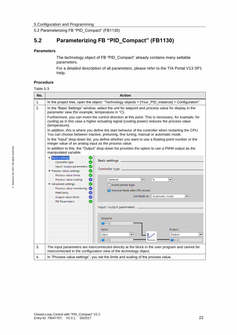
5.2 Parameterizing FB “PID_Compact” (FB1130)
Parameters
The technology object of FB “PID_Compact” already contains many settable parameters.
For a detailed description of all parameters, please refer to the TIA Portal V13 SP1 Help.
Procedure
Table 5-3
No. Action
1. In the project tree, open the object: “Technology objects > [Your_PID_instance] > Configuration”.
2. In the “Basic Settings” window, select the unit for setpoint and process value for display in the parameter view (for example, temperature in °C).
Furthermore, you can invert the control direction at this point. This is necessary, for example, for cooling as in this case a higher actuating signal (cooling power) reduces the process value (temperature).
In addition, this is where you define the start behavior of the controller when restarting the CPU. You can choose between inactive, pretuning, fine tuning, manual or automatic mode.
In the “Input” drop-down list, you define whether you want to use a floating-point number or the integer value of an analog input as the process value.
In addition to this, the “Output” drop-down list provides the option to use a PWM output as the manipulated variable.
3. The input parameters are interconnected directly at the block in the user program and cannot be interconnected in the configuration view of the technology object.
4. In “Process value settings”, you set the limits and scaling of the process value.

5 Configuration and Programming
5.2 Parameterizing FB “PID_Compact” (FB1130)
Closed-Loop Control with "PID_Compact" V2.2 Entry-ID: 79047707, V2.0.1, 03/2017 23
S
iem
en
s A
G 2
01
7 A
ll ri
gh
ts r
ese
rve
d
No. Action
5. Among other things, “Advanced settings” allows you to read out the current PID parameters and change them if necessary. However, you do not need to manually enter these parameters as they are adjusted during optimization.
In “Output value limits”, you will find the “Reaction to error” settings. You can select whether the controller should be inactive or output a substitute value or the last valid value while the error is pending (for example, if the process value limits are violated).
6. Save your changes or use “Online > Download and reset PLC program” to download the user program to the CPU.

5 Configuration and Programming
5.3 Commissioning FB “PID_Compact” (FB1130)
Closed-Loop Control with "PID_Compact" V2.2 Entry-ID: 79047707, V2.0.1, 03/2017 24
S
iem
en
s A
G 2
01
7 A
ll ri
gh
ts r
ese
rve
d
For a detailed list of the individual parameters, including a description, please refer to the “SIMATIC S7-1200, S7-1500 PID Control” Function Manual (\4\), chapter “Configuring PID_Compact V2“. For more help, press “F1” when the focus is on the “PID_Compact” block.
5.3 Commissioning FB “PID_Compact” (FB1130)
When you have made your desired configuration settings on the controller, you can commission the controller.
You can:
Use the existing commissioning tool and have STEP 7 calculate the controller parameters via pretuning and fine tuning (chapter 5.3.1).
Transfer your own calculated controller parameters to the controller (chapter 5.3.2).
5.3.1 Commissioning with pretuning and fine tuning
Table 5-4 Pretuning and fine tuning
No. Action Comment
1. Make sure that the correct controller structure (PI or PID parameters) has been set.
The individual scenarios use only the PID controller structure.
In the project tree, navigate to “[Your_CPU] > Technology objects > [Your_PID_Compact] > Configuration > PID Parameters > Controller structure”.
To find the suitable controller for a controlled system, please refer to the technical literature, for example \4\, chapter 2.7.
2. Use, for example, a MOVE command to interconnect
the output of the PID controller with the input of the controlled system.
the output of the controlled system with the input of the PID controller.
3. Use “Online > Download and reset PLC program” to download the PLC program to your CPU.
4. In the “PidCompact1” technology object, double-click “Commissioning”.
In “Measurement”, click “Start” to go online.
Now you can see the values for Setpoint, Input and Output in a graphic representation.
5 Configuration and Programming
5.3 Commissioning FB “PID_Compact” (FB1130)
Closed-Loop Control with "PID_Compact" V2.2 Entry-ID: 79047707, V2.0.1, 03/2017 25
S
iem
en
s A
G 2
01
7 A
ll ri
gh
ts r
ese
rve
d
No. Action Comment
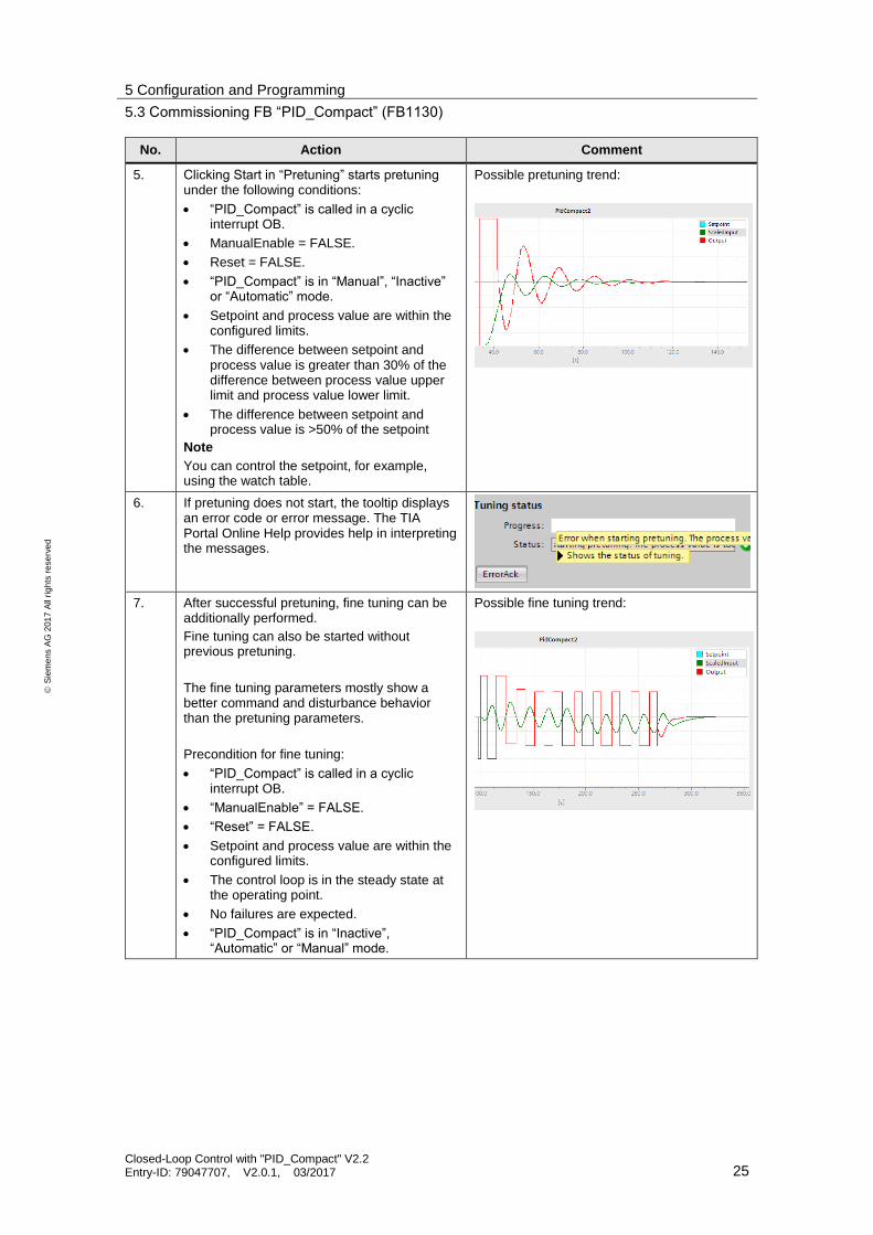
5. Clicking Start in “Pretuning” starts pretuning under the following conditions:
“PID_Compact” is called in a cyclic interrupt OB.
ManualEnable = FALSE.
Reset = FALSE.
“PID_Compact” is in “Manual”, “Inactive” or “Automatic” mode.
Setpoint and process value are within the configured limits.
The difference between setpoint and process value is greater than 30% of the difference between process value upper limit and process value lower limit.
The difference between setpoint and process value is >50% of the setpoint
Note
You can control the setpoint, for example, using the watch table.
Possible pretuning trend:
6. If pretuning does not start, the tooltip displays an error code or error message. The TIA Portal Online Help provides help in interpreting the messages.
7. After successful pretuning, fine tuning can be additionally performed.
Fine tuning can also be started without previous pretuning.
The fine tuning parameters mostly show a better command and disturbance behavior than the pretuning parameters.
Precondition for fine tuning:
“PID_Compact” is called in a cyclic interrupt OB.
“ManualEnable” = FALSE.
“Reset” = FALSE.
Setpoint and process value are within the configured limits.
The control loop is in the steady state at the operating point.
No failures are expected.
“PID_Compact” is in “Inactive”, “Automatic” or “Manual” mode.
Possible fine tuning trend:

5 Configuration and Programming
5.3 Commissioning FB “PID_Compact” (FB1130)
Closed-Loop Control with "PID_Compact" V2.2 Entry-ID: 79047707, V2.0.1, 03/2017 26
S
iem
en
s A
G 2
01
7 A
ll ri
gh
ts r
ese
rve
d
5.3.2 Commissioning with specified PID parameters
If you do not want to use the optimization functions but your own parameters for the PID controller, follow the instructions in the table below.
Table 5-5
No. Action
1. Choose the technology object In the project view and open the configuration window of the controller you want to set.
2. Navigate to “PID Parameters” and check the “Enable manual entry” check box.
Now you can enter your parameters for the PID controller.
3. Then go to the “Basic settings”, check the “Activate Mode after CPU restart” check box and select the “Automatic mode” item in the drop-down list.
Note!
When you have interconnected the “Mode” and “ModeActivate” inputs, make sure that Mode = 3 (corresponds to automatic mode).

5 Configuration and Programming
5.3 Commissioning FB “PID_Compact” (FB1130)
Closed-Loop Control with "PID_Compact" V2.2 Entry-ID: 79047707, V2.0.1, 03/2017 27
S
iem
en
s A
G 2
01
7 A
ll ri
gh
ts r
ese
rve
d
No. Action
4. Now use “Online > Download and reset PLC program” to download the user program to the CPU.
Your manually entered parameters have been applied and “PID_Compact” controls the system with these parameters.

5 Configuration and Programming
5.4 Inserting a function block of the simulation library
Closed-Loop Control with "PID_Compact" V2.2 Entry-ID: 79047707, V2.0.1, 03/2017 28
S
iem
en
s A
G 2
01
7 A
ll ri
gh
ts r
ese
rve
d
5.4 Inserting a function block of the simulation library
Documentation
The download page of this entry (\1\) additionally provides a description of the STEP 7 V13 SP1 library (Table 2-5) supplied with the project.
Procedure
The following table shows how to insert the simulation block FB, “Sim_PT3” (FB54), into a user program and configure it. The other simulation elements are integrated in the same way.
Table 5-6 Inserting the system simulation
No. Action Comment
1. Download the library file (Table 2-5) and extract the file on your engineering station.
2. In the right-hand pane, open the “Libraries” tab and click “Open global library”.
Navigate to the storage location of the extracted folder and double-click to open the “LSim” file.
2
1
3. Create a cyclic interrupt OB with a cycle time of, for example, 300 ms.
4. Drag the “LSim_PT3” block from the “Master copies” of the library to the cyclic OB. Create an instance data block for the function block.
It is necessary that the simulation blocks are called in a cyclic interrupt OB.

5 Configuration and Programming
5.5 Simulation of a controlled system with multiple elements
Closed-Loop Control with "PID_Compact" V2.2 Entry-ID: 79047707, V2.0.1, 03/2017 29
S
iem
en
s A
G 2
01
7 A
ll ri
gh
ts r
ese
rve
d
No. Action Comment
5. Call the block in the cyclic OB that has already been created and interconnect the parameters, for example, as follows:
gain = 1.0
tmLag1 = 29.0
tmLag2 = 17.5
tmLag3 = 3.1
cycle = 0.3
Also interconnect the “Reset” input with a controllable Boolean variable.
Note
The “cycle” parameter must correspond to the cycle time of the calling cyclic interrupt OB.
5.5 Simulation of a controlled system with multiple elements
Interconnecting controlled systems
Serial or parallel interconnection of controlled systems allows mapping even more complex real processes with the aid of the controlled system simulation library.
The steps for inserting a controlling element are the same as for inserting a PT3 system described in Table 5-6.
Serial interconnection
As an example, this section describes the implementation of a controlled system that consists of four serial simulation elements.
Figure 5-1
PIDcontroller
Reference
variable
Feedback
PT1 PDT1
Lagging PT2osc
MV
Controlled system
The following table describes the actions for inserting a controlled system that consists of multiple serial elements. Specifically, this is the example from Scenario2.

5 Configuration and Programming
5.5 Simulation of a controlled system with multiple elements
Closed-Loop Control with "PID_Compact" V2.2 Entry-ID: 79047707, V2.0.1, 03/2017 30
S
iem
en
s A
G 2
01
7 A
ll ri
gh
ts r
ese
rve
d
Table 5-7
No. Action Comment
1. Add the controlling elements you want to use as described in Table 5-6. In Scenario2, these are the following controlling elements:
PT1 (FB “LSim_PT1”)
PDT1 (FB “LSim_PDT1”)
Lag element (FB “LSim_Lagging”)
PT2 in the periodic case. (FB “LSim_PT2osc”)
2. Use MOVE commands to interconnect the outputs of the controlling elements with the input of the respective following controlling element.
3. As described in Table 5-2, add “PID_Compact” to your project and interconnect (also using a MOVE command) the output of the controller with the input of the first controlling element.
Interconnect the input of the controller with the output of the last controlling element.
4. Now you have set up a complete control loop.
To download the controlled systems to the CPU, compile your program and download it to the CPU.
Note
If you want to view the step response of the controlled system without closed-loop control (5), click “Start” (1) in the commissioning window “[Your_CPU] > Technology objects > [Your_PID] > Commissioning”. Then set the PID controller to Manual mode (2) and set a step change for the controlled system (set the output to a fixed value (3+4)).
2
34
5
1

5 Configuration and Programming
5.5 Simulation of a controlled system with multiple elements
Closed-Loop Control with "PID_Compact" V2.2 Entry-ID: 79047707, V2.0.1, 03/2017 31
S
iem
en
s A
G 2
01
7 A
ll ri
gh
ts r
ese
rve
d
Parallel interconnection
As an example, this section describes the implementation of a controlled system that consists of two parallel simulation elements.
Figure 5-2
Reference
variable
PIDcontroller
Feedback
PT1
PDT1
+
Both controlling elements receive the same input signal from the PID controller. Their output signals are added and returned to the controller.
Table 5-8
No. Action
1. Add the controlling elements you want to use as described in Table 5-6. In this example, these are the following ones:
PT1 (FB “LSim_PT1”)
PDT1 (FB “LSim_PDT1”)
2. Use two Move commands to interconnect the output of the PID controller with the input
of the PT1 element.
of the PDT1 element.
3. Add the output values of the two controlled systems.
4. Assign the added and, if necessary, scaled output signal as an input to the PID controller.

6 Installation and Startup
6.1 Startup with the entire hardware
Closed-Loop Control with "PID_Compact" V2.2 Entry-ID: 79047707, V2.0.1, 03/2017 32
S
iem
en
s A
G 2
01
7 A
ll ri
gh
ts r
ese
rve
d
6 Installation and Startup This chapter describes how to commission the supplied TIA Portal project.
You can either use the hardware described in chapter 2.4.2 (for commissioning, see chapter 6.1) or completely simulate the project with PLCSIM (for commissioning, see chapter 6.2).
6.1 Startup with the entire hardware
6.1.1 Installing the hardware
The figure below shows a possible hardware configuration of the application. A configuration without the intermediate switch is also possible.
Figure 6-1
Industrial Ethernet
Field PG CPU 1516-3 PN/DP
PC station
230V
230V
Switch
Note Always follow the installation guidelines for SIMATIC S7 systems (see also \6\ and \7\).

6 Installation and Startup
6.1 Startup with the entire hardware
Closed-Loop Control with "PID_Compact" V2.2 Entry-ID: 79047707, V2.0.1, 03/2017 33
S
iem
en
s A
G 2
01
7 A
ll ri
gh
ts r
ese
rve
d
Table 6-1
No. Action Comment
1. Attach the switch, the S7-1500 CPU and the power supply to a DIN rail.
2. Connect the S7-1500 CPU and the switch to the power supply.
3. Use an Ethernet cable to connect your engineering PC and the S7-1500 CPU to the switch via the X1 interface.
4. Supply the power supply with 230V AC.
5. Set the IP address of the X1 port of the S7-1500 in the display to the IP address used in the example (192.168.0.1).
The IP address can be set in the display in “Settings > Addresses >X1 (IE/PN)”.
Note
For downloading to the CPU, the engineering station should be in the same subnet.
Note The use of a field PG as an engineering station and at the same time as a PC station is described here.
Alternatively, for example, a rack PC can be used for visualization.
6.1.2 Installing the software
This chapter describes the steps for installing the programs used.
Table 6-2 Installing the software components
No. Action Comment
1. Install STEP 7 Professional V13.0 SP1
Follow the information provided in the system manual:
\3\
2. Install WinCC Professional V13.0 SP1 Follow the information provided in the system manual:
\8\
3. Download the sample project (Table 2-5) from the Siemens Online Support page (\1\).

6 Installation and Startup
6.1 Startup with the entire hardware
Closed-Loop Control with "PID_Compact" V2.2 Entry-ID: 79047707, V2.0.1, 03/2017 34
S
iem
en
s A
G 2
01
7 A
ll ri
gh
ts r
ese
rve
d
6.1.3 Configuring the hardware
Renaming the engineering station
The following table shows the procedure for changing the PC name in Windows 7:
Table 6-3 Renaming the engineering station
No. Action Comment
1. To download WinCC Runtime to your engineering station, the engineering station must have the PC name used in the project (“VisuPC”).
Alternatively, you can also adapt the name to your engineering station in the project.
2. Click “Start”. Go to the “Computer” context menu and click “Properties”. In the following window, below “Computer name, domain and workgroup settings”, click “Change settings”.
3. In the “System properties” window, select “Change” and then enter the new computer name, “VisuPC”, in the appropriate field.
4. Confirm and restart your engineering station to apply the computer name.
Setting the IP address of the engineering station
When using the engineering station simultaneously as a PC station for visualization, you have to assign the IP address specified in the project to the engineering station:
Table 6-4 Assigning the IP address
No. Action Comment
1. Open “Start > Control Panel > Network and Sharing Center”.
2. Click “Change Adapter Settings” and then select “Properties” in the context menu of your Ethernet adapter.
3. Select “Internet Protocol Version 4” and change the IP address as follows:
IP address: 192.168.0.251
Subnet mask: 255.255.255.0
4. Click OK to confirm the change.
Now your engineering station has the IP address assigned in the project (Table 2-5).
5. In addition, set your PG/PC interface (“Start > Control Panel > Set PG/PC Interface”) to TCP/IP and the network adapter you are using.

6 Installation and Startup
6.1 Startup with the entire hardware
Closed-Loop Control with "PID_Compact" V2.2 Entry-ID: 79047707, V2.0.1, 03/2017 35
S
iem
en
s A
G 2
01
7 A
ll ri
gh
ts r
ese
rve
d
6.1.4 Opening and downloading the TIA Portal project
Table 6-5
No. Action Comment
1. Download the zip project (Table 2-5) to your engineering station and unzip the folder.
2. In the program folder, double-click the icon with the “*.ap13” extension.
The project now opens in TIA Portal V13.
3. Go to the project view. Click the “PID_Compact_CPU1516” CPU and use “Online > Download and reset PLC program” to download the user program to the CPU.
4. When downloading the program for the first time, you have to specify your interface and the subnet for downloading. Then select the CPU to be downloaded.
5. Compile the visualization by clicking the context menu of WinCC RT Advanced > “Compile > Software (Rebuild all)”.
6. Click the “VisuPC” PC station and, for a graphic representation of the scenarios, click the appropriate icon to start WinCC Runtime.
7. Now you can monitor the individual tags and the trend of the setpoint, process value and output value of the PID controllers.
For a description of the WinCC user interface, please refer to chapter 7.

6 Installation and Startup
6.2 Startup with PLCSIM V13
Closed-Loop Control with "PID_Compact" V2.2 Entry-ID: 79047707, V2.0.1, 03/2017 36
S
iem
en
s A
G 2
01
7 A
ll ri
gh
ts r
ese
rve
d
6.2 Startup with PLCSIM V13
6.2.1 Installing the software
This chapter describes the steps for installing the programs used.
Table 6-6 Installing the software components
No. Action Comment
1. Install STEP 7 Professional V13 SP1
Follow the information provided in the system manual: \3\
2. Install PLCSIM V13 SP1 Follow the information provided in the system manual: \3\
3. Install WinCC Professional V13 SP1
Follow the information provided in the system manual: \8\
4. Download the sample project (Table 2-5) from the Siemens Online Support page (\1\).
6.2.2 Configuring the engineering station
Changing the PG/PC interface
Table 6-7
No.
Action Comment
1. Use “Start > Control Panel” to go to the Control Panel and select the “Set PG/PC Interface” icon.
2. Set your PG/PC interface to S7ONLINE (STEP 7) PLCSIM S7-1200/S7-1500(TCP/IP).
3. Click OK to confirm the interface and the displayed warning message.

6 Installation and Startup
6.2 Startup with PLCSIM V13
Closed-Loop Control with "PID_Compact" V2.2 Entry-ID: 79047707, V2.0.1, 03/2017 37
S
iem
en
s A
G 2
01
7 A
ll ri
gh
ts r
ese
rve
d
Starting PLCSIM V13
Table 6-8
No. Action Comment
1. Double-click the S7-PLCSIM V13 icon to start.
2. Create a new project and save it to your local drive.
After selecting a name, clicking “Create” creates the new project.
3. This makes the simulated CPU ready for use.
Clicking the button for the compact view gives you a good overview of the current operating state of the simulated CPU.

6 Installation and Startup
6.2 Startup with PLCSIM V13
Closed-Loop Control with "PID_Compact" V2.2 Entry-ID: 79047707, V2.0.1, 03/2017 38
S
iem
en
s A
G 2
01
7 A
ll ri
gh
ts r
ese
rve
d
6.2.3 Opening and downloading the TIA Portal project
Table 6-9
No. Action Comment
1. Download the zip project (Table 2-5) to your engineering station and unzip the folder.
2. In the program folder, double-click the icon with the “*.ap13” extension.
The project now opens in TIA Portal V13.
3. Click the “PidCompactCPU1516” CPU and use “Extended download to device” to download the user program to the CPU.
Select the following interface for downloading:
Type of the PG/PC interface: PN/IE
PG/PC interface: PLCSIM S7-1200/S7-1500
Connection to subnet: PN/IE_1
4. Click the “VisuPC” PC station and, for a graphic representation of the scenarios, click the appropriate icon to start WinCC Runtime.
5. Now you can monitor the individual tags and the trend of the setpoint, process value and output value of the PID controllers.
For a description of the WinCC user interface, please refer to chapter 7.

7 Operation of the application
7.1 Overview
Closed-Loop Control with "PID_Compact" V2.2 Entry-ID: 79047707, V2.0.1, 03/2017 39
S
iem
en
s A
G 2
01
7 A
ll ri
gh
ts r
ese
rve
d
7 Operation of the application
7.1 Overview
For a better overview of the behavior of the implemented scenarios, several options are available to the user:
Insight into the behavior of the control loops using the WinCC Runtime Advanced HMI system.
Detailed insight into the current status of the control loop through the watch tables already prepared in the CPU.
7.2 Operation via WinCC Runtime
7.2.1 Control elements
The different scenarios can be selected from the start screen of the WinCC Runtime system running on the “VisuPC” PC station.
The WinCC Runtime screens contain the following elements:
Table 7-1
No. Element
1. Trend view of setpoint, process value and controller output.
2. Output of the setpoint; manual input is possible.
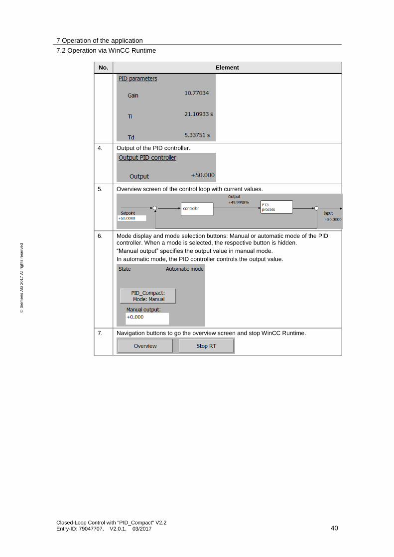
3. Output of the currently used PID parameters.
7 Operation of the application
7.2 Operation via WinCC Runtime
Closed-Loop Control with "PID_Compact" V2.2 Entry-ID: 79047707, V2.0.1, 03/2017 40
S
iem
en
s A
G 2
01
7 A
ll ri
gh
ts r
ese
rve
d
No. Element
4. Output of the PID controller.
5. Overview screen of the control loop with current values.
6. Mode display and mode selection buttons: Manual or automatic mode of the PID controller. When a mode is selected, the respective button is hidden.
“Manual output” specifies the output value in manual mode.
In automatic mode, the PID controller controls the output value.
7. Navigation buttons to go the overview screen and stop WinCC Runtime.

7 Operation of the application
7.2 Operation via WinCC Runtime
Closed-Loop Control with "PID_Compact" V2.2 Entry-ID: 79047707, V2.0.1, 03/2017 41
S
iem
en
s A
G 2
01
7 A
ll ri
gh
ts r
ese
rve
d
7.2.2 Monitoring Scenario 2 with WinCC
After commissioning the project, the two scenarios can be monitored using WinCC.
Table 7-2 describes a possible monitoring scenario for Scenario2.
Table 7-2
No. Action
1. Start the visualization and in the start screen, select “Scenario2”.
2. To initially monitor a step response of the controlled system, select Manual mode ( ).
Set “Manual output” to any value ( ).
1
2
Now you can monitor the system’s step response to the trigger:

7 Operation of the application
7.3 Operator control and monitoring via online access
Closed-Loop Control with "PID_Compact" V2.2 Entry-ID: 79047707, V2.0.1, 03/2017 42
S
iem
en
s A
G 2
01
7 A
ll ri
gh
ts r
ese
rve
d
No. Action
3. To monitor the control behavior, select Automatic mode ( ) and define a setpoint ( ).
12
Now you can monitor the behavior of the control loop:
7.3 Operator control and monitoring via online access
Overview
You can analyze the S7 program of the CPU via CPU online access and the monitoring of blocks.
Watch tables
Two watch tables have already been inserted into the project for support. They contain important parameters of the individual blocks for the individual scenarios. You will find the watch tables in the project tree of the “PidCompactCPU1516” folder in “Watch and force tables”:
WatchTableScenario1
WatchTableScenario2

8 Related literature
Closed-Loop Control with "PID_Compact" V2.2 Entry-ID: 79047707, V2.0.1, 03/2017 43
S
iem
en
s A
G 2
01
7 A
ll ri
gh
ts r
ese
rve
d
8 Related literature
Book directory
Table 8-1
Topic
\1\ Praxisbuch für Regelungen mit SIMATIC S7 und SIMATIC PCS 7 für die Prozessautomatisierung
Authors: Müller/ Pfeiffer/ Wieser
Publicis Publishing, Erlangen
ISBN: 978-3-89578-340-1
Link directory
Table 8-2
Topic
\1\ Siemens Industry Online Support
https://support.industry.siemens.com
\2\ Download page of this entry https://support.industry.siemens.com/cs/ww/en/view/79047707
\3\ System Manual: STEP 7 Professional V13.1
https://support.industry.siemens.com/cs/ww/en/view/109011420
\4\ Function Manual: SIMATIC S7-1200, S7-1500: PID Control
https://support.industry.siemens.com/cs/ww/en/view/108210036
\5\ System Manual: SIMATIC S7-1500 Automation System
https://support.industry.siemens.com/cs/ww/en/view/59191792
\6\ Getting Started: SIMATIC S7-1500: Installing the Assembly
https://support.industry.siemens.com/cs/ww/en/view/71704272/52316681355
\7\ Getting Started: SIMATIC S7-1500: Wiring
https://support.industry.siemens.com/cs/ww/en/view/71704272/53386475915
\8\ System Manual: WinCC Professional V13 SP1
https://support.industry.siemens.com/cs/ww/en/view/109096785
\9\ Application Example: “3-Point Stepper Control with SIMATIC S7-1500” https://support.industry.siemens.com/cs/ww/en/view/68011827
\10\ Application Example: „Single and Multi Loop Controller Structures (Cascade Control) with PID_Temp” https://support.industry.siemens.com/cs/ww/en/view/103526819
9 History
Table 9-1
Version Date Modifications
V1.0 09/2013 First version
V2.0 03/2016 Update to “PID_Compact” V2.2 (TIA V13 SP1)
V2.0.1 03/2017 Adjustment Table 2-5