application guide flatair - flck/flhk
TRANSCRIPT

Providing indoor climate comfort
FLATAIR - FLCK/FLHK
Application guide
MSL60E-0701 12-2006

1
Congratulations you have made a wise choice and we feel sure that it will meet your expectation
INDEX
CONTENTS
• GENERAL DESCRIPTION• DENOMINATION• PRODUCT RANGE• PHYSICAL DATA• ELECTRICAL DATA• FAN SERVICES• SOUND DATA• CAPACITIES TABLE• UNIT DIMENSIONS• BLOWER DIMENSIONS STANDARD AND OPTIONAL• UNIT INSTALLATION• PIPES CONNEXIONS• ELECTRICAL CONNEXIONS• OPERATING LIMITS• OPTIONS
PAGE
2-345
6-89-10
1112
13-1920-31
32-3536-37
383940
41-42
Lennox have been providing environmental solutions since 1895, our range of FLATAIR continues to meet thestandards that have made LENNOX a household name. Flexible design solutions to meet YOUR needs anduncompromising attention to detail. Engineered to last, simple to maintain and Quality that comes as standard.Information on local contacts at www.lennoxeurope.com.
All the technical and technological information contained in this manual, including any drawing and technicaldescriptions provided by us, remain the property of Lennox and must not be utilised (except in the operation ofthis product), reproduced, issued to or made available to third parties without the prior written agreement of Lennox.

2
Made-up with copper pipes and aluminium wings,designed to get a high heating transfer.Their dimensions and design of the circuits havebeen specially worked to obtain the maximumperformance of the exchanger increasing the powerof the unit and reducing the consumption.
All units are provided with scroll compressor, coolingby a suction gas with thermic protection inside theengine, so no other additional protection is required.It is mounted on anti-vibration devices both externaland internal.On units 24/28/30 the compressors have a screwedconnection into the pipe- Thus, they can be moreeasily to assembled.In heat pump units the compressors are providedwith a crankcase heater to heat the oil in thecompressor so that a suitable lubrication can takeplace.
FURNITURE
EXCHANGER
COOLING CIRCUITCOMPRESSORS
FANOutdoor and indoor fans are centrifugal with anassembled engine, statically balancing, with a lowsound level.Those fans are assembled to the inserted panel ofthe units and split from upper side of the fan withinsulated materials to void vibrations.
Carried out with welded deshydratable copper pipeswith pressuring outlets with plugged valves in thesuction and liquid lines both indoors and outdoorunits.In unit 24-28-30 the pressuring outlets in the outdoorsection are approachable from the outer part of theunit.The unit is equipped with both high-low pressureswitches with an automatic rearm. It also has adehumidifying filter, expansion system withrestrictors in units 10-12-16; stoppage ofimpurities/dirts and air reducing valves in units 22-24-28-30. The heat pump units are equipped aswell with a suction pump battery to avoid the leaksto the compressor, reversible valves to reserve thecycle of unidirectional valve.
Washable air filter; auto extinguishable material withM1 classification, high efficiency filtrate with G2classification. It can be removed through the upperand the sizes.
GENERAL DESCRIPTION
The horizontal air conditioning units, range Flatair, cooling only or heat pump are air condensed units designedfor small shopping center and housing. Those units have two sections: outdoors and indoors. They can be suppliedeither compact or on split system.Due to their small dimensions they are designed for false ceiling and can be placed in air conducts both indoorsand outdoors.A wide range of optionals, completed-factory assembled are also available.
AIR FILTER
ELECTRICAL CIRCUIT
Designed according to EN 60204-1 normativehermetically sealed to avoid condensation. Withprotective fuses for compressors and fans. All theengines in compressors and fans have internalthermic protectors and an electronic control platecontrols the unit.
Painted in galvanized metal furniture, high resistantto corrosion. The units are provided with metalprofiles, capable of withstanding the unit and ableas well of installing the unit hung from the ceiling ormounted on the floor.The panel are easily inter exchangeable, givingseveral air suction and return alternatives.The outdoor sections are equipped with a meta grilleswith in the blower panel " except in models 24-28-30 and in the duct discharge to avoid damages (inthe whole models).An insulation with a protection of mesh is used inindoor units with a classification of M1 and F1,certifying that the material is auto-extinguishableand avoiding the fumes inside the room to beaconditionned. The auto extinguishable insulationM1 is used in indoor units.

3
PHOTOGRAPHY CORRESPONDING TO A TERMINAL THERMOSTAT.
GENERAL DESCRIPTION
CONTROL
Made up with a printed control circuit plate for the opening unit and with a walled terminal thermostat to be placedin the room to be aconditioned; with sound output inside the terminal and with a sound installed in the outdoorbatteries for the regulation of the system.With a LCD display with alarm visualization, exclusive connection with two files between terminal thermostat andelectrical box in the unit, possibility to adjust internal parameters. automatic restarting and high pressure controlON/OFF on unit models 22-24-28-30, with well intelligent defrosting control adapted to ambient conditions in eachmoment and each side (for small heat pump).
• Heating electrical heater, type armoured pipe to be mounted into the unit.• Hot water coil.• Head pressure control ON/OFF for models 10-12-16.• Crankcase for units cooling only.• Main switch.• Phase sequencer (3 phase unit).• Hot gas bypass valve.• Control programmable controller.• Remote duct sensor on return.• Ambient remote sensor.• Thermostatic freecooling.• Sound muffler.• External mounting kit.• Freecooling external mounted kit.• Outdoor air filter.
OPTIONS

4
ApplicationC: Cooling onlyH: Heat pump
Type of refrigerantA: R-22K: R-407C
Unit size.Approximately coolingcapacity in kW.
ApplicationC: Cooling onlyH: Heat pumpX: Cooling only and heat pump units
Type of refrigerantA: R-22K: R-407CO: R-22 y R-407C
Unit size.Approximate coolingcapacity in kW.
DENOMINATION
F L C K 22
Type of unitHorizontal compact
FLATAIR
PACKAGED UNITS
K F C K 22
Type of unitK: Outdoor unitL: Indoor unit
Type of unitFLATAIR
INDOOR UNIT + OUTDOOR UNIT

5
RANGE PRODUCT
KFCK 10FLCK 10
MODEL OUTDOORUNIT
INDOORUNIT V / Ph / 50 Hz
NOMINALCAPACITY W
COOLING COOLING
MODEL V / Ph / 50 HzCOOLING H. PUMP COOLING H. PUMP
UNITS COOLING ONLY WITH REFRIGERANT R-407C
UNITS HEAT PUMP WITH REFRIGERANT R-22
NOMINALCONSUMPTION kW
LFXO 10230-400V/3Ph
KFCK 12FLCK 12 LFXO 12 230-400V/3Ph
KFCK 16FLCK 16 LFXO 16 230-400V/3Ph
230-400V/3Ph
KFCK 28FLCK 28 LFCK 28 230-400V/3Ph
KFCK 30FLCK 30 LFCK 30 230-400V/3Ph
9.800 3,68
11.800 4,57
15.300 6,40
19.500 8,09
26.300 10,40
28.100 12,20
230-400V/3Ph
230-400V/3Ph
230-400V/3Ph
230-400V/3Ph
230-400V/3Ph
230-400V/3Ph
KFCK 24FLCK 24 LFCK 24 230-400V/3Ph 22.000 9,02
KFHA 10FLHA 10
KFHA 12FLHA 12
KFHA 16FLHA 16
KFHA 28FLHA 28 LFHA 28
KFHA 30FLHA 30 LFHA 30
KFHA 24FLHA 24 LFHA 24 230-400V/3Ph
OUTDOORUNIT
INDOORUNIT
KFCK 22FLCK 22 LFCK 22
230V/1Ph
KFCK 10FLCK 10
KFHA 22FLHA 22 LFHA 22
KFHA 10FLHA 10LFXO 10
LFXO 12
LFXO 16
230V/1Ph
UNITS HEAT PUMP WITH REFRIGERANT R-407C
MODEL V / Ph / 50 HzCOOLING H. PUMP COOLING H. PUMP
230-400V/3Ph
230-400V/3Ph
230-400V/3Ph
230-400V/3Ph
230-400V/3Ph
230-400V/3Ph
KFHK 10FLHK 10
KFHK 12FLHK 12
KFHK 16FLHK 16
KFHK 28FLHK 28 LFHK 28
KFHK 30FLHK 30 LFHK 30
KFHK 24FLHK 24 LFHK 24 230-400V/3Ph
OUTDOORUNIT
INDOORUNIT
KFHK 22FLHK 22 LFHK 22
KFHK 10FLHK 10LFXO 10
LFXO 12
LFXO 16
230V/1Ph9.800
11.800
15.300
19.500
26.300
28.100
22.000
10.000
12.000
15.500
20.200
27.000
28.700
22.500
9.400
11.300
14.700
19.200
26.000
27.600
21.000
10.300
12.300
15.600
20.000
27.000
29.800
22.800
3,68
4,57
6,40
8,09
10,40
12,20
9,02
3,16
4,11
5,60
6,74
9,20
10,32
8,60
3,50
4,31
6,11
7,92
10,36
11,78
8,80
2,93
3,44
4,94
6,60
8,43
9,43
7,80
NOMINALCAPACITY W
NOMINALCONSUMPTION kW
NOMINALCAPACITY W
NOMINALCONSUMPTION kW

6
(1) With admissible minimum air flow.
PHYSICAL DATA (COOLING ONLY)
(*) Air intake temperature in the indoor exchanger 27ºC DB/19ºC WB(*) Air intake temperature in the outdoor exchanger: 35ºC DB
Cooling capacity
COMPRESSOR
OUTDOOR UNIT
No. / Type
FAN
NET WEIGHT
PIPES CONNEXIONSLiquid
Gas
INDOOR UNIT
NET WEIGHT
PIPES CONNEXIONSLiquidGas
SET
DB.- Dry bulb temperatureWB.- Wet bulb temperature
FLCK 12FLCK 10
KFCK 12KFCK 10
430 430
70 70
1/2''
3/4''
kW
Kg
Kg
KFCK 16
820 820 830
100
500
3/8''
7/8''
FLCK 16 FLCK 22
KFCK 22
1 / Scroll 1 / Scroll 1 / Scroll 1 / Scroll
900
130
620
5/8''
FLCK 24 FLCK 30
KFCK 24 KFCK 30
1025 1025
140 150
775 775
5/8'' 5/8''
1-1/8'' 1-1/8''
1 / Scroll 1 / Scroll
FLCK 28
KFCK 28
1025
150
775
5/8''
1-1/8''
1 / Scroll
LFXO 12LFXO 10 LFXO 16 LFCK 22 LFCK 24 LFCK 30LFCK 28
Maximum air flow
9,8 11,8
130 135 180
15,3 19,5
24002350 3750 4350
195
Maximum available pressure 100 90 120 150Pa
22,0 28,1
4500 5250
160 100
265 285
26,3
5000
120
275
NET WEIGHT Kg 200 205 280 325 405 430425
DIMENSIONSHeightWidthDepth
mm.
mm.
mm.
495
1250
1250
495
1250
1250
595
1330
1300
595
1520
1450
645
1800
1500
645
1800
1500
645
1800
1500
495
1250
495
1250
595
1300
595
1450
645
1500
645
1500
645
1500
495
1250
495
1250
595
1300
595
1450
645
1500
645
1500
645
1500
(*)
R-407C
m /h.3
34003500 4950 5900 6600 64006400
Minimum air flow
(1)
FANMaximum air flow
16501500 2400 3200
Maximum available pressure 120 110 160 180Pa
4000 4500
240 180
4250
200
m /h.3
23002350 3700 5350 6300 60006000
Minimum air flow
(1)
DIMENSIONSHeightWidthDepth
mm.
mm.
mm.
m /h.3
m /h.3
DIMENSIONSHeightWidthDepth
mm.
mm.
mm.
3/4'' 7/8''
3/8''
1/2''
3/4''
3/8''
7/8''
5/8'' 5/8'' 5/8''
1-1/8'' 1-1/8''
5/8''
1-1/8''3/4'' 7/8''
3/8''

7
(*)(**)
R-22
(1) With admissible minimum air flow.
PHYSICAL DATA UNITS HEAT PUMP
Cooling capacity
DB.- Dry bulb temperatureWB.- Wet bulb temperature
9,4 11,3kW 14,7 19,2 21,0 27,6
(*) Air intake temperature in the indoor exchanger: 27ºC DB/19ºC WB(*) Air intake temperature in the outdoor exchanger: 35ºC DB(**) Air intake temperature in the indoor exchanger: 20ºC DB / 12ºC WB(**) Air intake temperature in the outdoor exchanger: 7ºC DB / 6ºC WB
Heating capacity kW 10,3 12,3 15,6 20,0 22,8 29,8
FLHA 12FLHA 10
KFHA 12KFHA 10 KFHA 16
FLHA 16 FLHA 22
KFHA 22
FLHA 24
KFHA 24 KFHA30
FLHA 28
KFHA 28
FLHA 30
26,0
27,0
COMPRESSOR
OUTDOOR UNIT
No. / Type
NET WEIGHT
INDOOR UNIT
SET
Kg
1 / Scroll 1 / Scroll 1 / Scroll 1 / Scroll 1 / Scroll 1 / Scroll1 / Scroll
LFXO 12LFXO 10 LFXO 16 LFHA 22 LFHA 24 LFHA30LFHA 28
135 140 185 200 270 285280
NET WEIGHT Kg 205 210 285 330 410 435430
DIMENSIONSHeightWidthDepth
mm.
mm.
mm.
495
1250
1250
495
1250
1250
595
1330
1300
595
1520
1450
645
1800
1500
645
1800
1500
645
1800
1500
PIPES CONNEXIONSLiquid
Gas
820 820 830 900 1025 10251025
495
1250
495
1250
595
1300
595
1450
645
1500
645
1500
645
1500
DIMENSIONSHeightWidthDepth
mm.
mm.
mm.
1/2''
3/4''
3/8''
7/8''
5/8'' 5/8'' 5/8''
1-1/8'' 1-1/8''
5/8''
1-1/8''3/4'' 7/8''
3/8''
FANMaximum air flow
24002350 3750 4350
Maximum available pressure 100 90 120 150Pa
4500 5250
160 100
5000
120
m /h.3
34003500 4950 5900 6600 64006400
Minimum air flow(1)
m /h.3
NET WEIGHT
PIPES CONNEXIONSLiquid
Gas
430 430
70 70
1/2''
3/4''
Kg 100
500
3/8''
7/8''
130
620
5/8''
140 150
775 775
5/8'' 5/8''
1-1/8'' 1-1/8''
150
775
5/8''
1-1/8''
495
1250
495
1250
595
1300
595
1450
645
1500
645
1500
645
1500
FANMaximum air flow
16501500 2400 3200
Maximum available pressure 120 110 160 180Pa
4000 4500
240 180
4250
200
m /h.3
23002350 3700 5350 6300 60006000
Minimum air flow
(1)
m /h.3
DIMENSIONSHeightWidthDepth
mm.
mm.
mm.
3/4'' 7/8''
3/8''

8
(*)(**)
R-407C
(1) With admissible minimum air flow.
PHYSICAL DATA UNITS HEAT PUMP
DB.- Dry bulb temperatureWB.- Wet bulb temperature
(*) Air intake temperature in the indoor exchanger: 27ºC DB/19ºC WB(*) Air intake temperature in the outdoor exchanger: 35ºC DB(**) Air intake temperature in the indoor exchanger: 20ºC DB / 12ºC WB(**) Air intake temperature in the outdoor exchanger: 7ºC DB / 6ºC WB
FLHK 12FLHK 10
KFHK 12KFHK 10 KFHK 16
FLHK 16 FLHK 22
KFHK 22
FLHK 24
KFHK 24 KFHK 30
FLHK 28
KFHK 28
LFHK 22 LFHK 24 LFHK 30LFHK 28
FLHK 30
Cooling capacity 9,8 11,8kW 15,3 19,5 22,0 28,1
Heating capacity kW 10,0 12,0 15,5 20,2 22,5 28,7
26,3
27,0
COMPRESSOR
OUTDOOR UNIT
No. / Type
INDOOR UNIT
SET
1 / Scroll 1 / Scroll 1 / Scroll 1 / Scroll 1 / Scroll 1 / Scroll1 / Scroll
LFXO 12LFXO 10 LFXO 16
NET WEIGHT Kg 205 210 285 330 410 435430
DIMENSIONSHeightWidthDepth
mm.
mm.
mm.
495
1250
1250
495
1250
1250
595
1330
1300
595
1520
1450
645
1800
1500
645
1800
1500
645
1800
1500
NET WEIGHT Kg 135 140 185 200 270 285280
PIPES CONNEXIONSLiquid
Gas
820 820 830 900 1025 10251025
495
1250
495
1250
595
1300
595
1450
645
1500
645
1500
645
1500
DIMENSIONSHeightWidthDepth
mm.
mm.
mm.
1/2''
3/4''
3/8''
7/8''
5/8'' 5/8'' 5/8''
1-1/8'' 1-1/8''
5/8''
1-1/8''3/4'' 7/8''
3/8''
FANMaximum air flow
24002350 3750 4350
Maximum available pressure 100 90 120 150Pa
4500 5250
160 100
5000
120
m /h.3
34003500 4950 5900 6600 64006400
Minimum air flow
(1)
m /h.3
NET WEIGHT
PIPES CONNEXIONSLiquidGas
430 430
70 70
1/2''
3/4''
Kg 100
500
3/8''
7/8''
130
620
5/8''
140 150
775 775
5/8'' 5/8''
1-1/8'' 1-1/8''
150
775
5/8''
1-1/8''
495
1250
495
1250
595
1300
595
1450
645
1500
645
1500
645
1500
FANMaximum air flow
16501500 2400 3200
Maximum available pressure 120 110 160 180Pa
4000 4500
240 180
4250
200
m /h.3
23002350 3700 5350 6300 60006000
Minimum air flow
(1)
m /h.3
DIMENSIONSHeightWidthDepth
mm.
mm.
mm.
3/4'' 7/8''
3/8''

9
R-22
Compressor (heating cycle)
Fan outdoor section
Compressor
Fan outdoor section
Compressor (cooling cycle)
Start up current
Maximum current
V/f (50 Hz)
V/f (50 Hz)
V/f (50 Hz)
FLHA 12FLHA 10 FLHA 16 FLHA 22 FLHA 24 FLHA 28 FLHA 30
Voltage230V-400V/ 3Ph
230V/ 1Ph
Rated absorbed power
Total power in cooling cycleTotal power in heating cycle
kW
kW
Maximum currentTotal current
Start up current
KFHA 12KFHA 10 KFHA 16 KFHA 22 KFHA 24 KFHA 28 KFHA 30
Rated absorbed power
2,03 2,54kW 2,94 3,70 4,85 6,485,48
Total power in cooling cycleTotal power in heating cycle
Voltage230V-400V/ 3Ph
230V/ 1Ph
kW
kW
kW 0,52 0,52 1,10 1,60 1,60 1,601,60
Maximum current
Total current
Start up current
2,60 3,41kW 4,11 5,02 5,85 8,837,41
LFXO 12LFXO 10 LFXO 16
Rated absorbed power
Voltage230V-400V/ 3Ph
230V/ 1Ph
0,38 0,38 0,90 1,30 1,35 1,351,35kW
LFHA 22 LFHA 24 LFHA 28 LFHA 30
ELECTRICAL DATA
UNIT MODELS
3,50 4,31 6,11 7,92
2,93 3,44 4,94 6,60
8,80 11,78
7,80 9,43
10,36
8,43
A 52,0/30,044,0/25,439,8/23,037,2/21,531,7/18,325,0/14,422,4/12,9
24,3
A240/136226/132182/108193/110145/73104/5697/52
101
UNIT MODELS
A
A
3,12 3,93 5,21 6,62
16,7/7,2 19,3/8,7 19,9/11,5 22,4/12,9
2,55 3,06 3,50 5,30
7,45 10,43
6,45 8,08
25,3/14,6 36,5/21,0
9,01
7,08
28,5/16,3
A44,6/25,736,6/21,033,4/19,329,8/17,224,7/14,322,4/11,819,8/10,3
A 232/132218/128174/104185/105138/69101/5394/49
98
21,7
3,1 3,14,8/2,8 7,4/4,3 8,1/4,7 8,1/4,7 8,1/4,7
18,6
UNIT MODELS
A 7/4 7,4/4,3
A22/1421/13
7,87,8
2,6 2,67,4/4,3 7,4/4,3 7,4/4,3
22/14 22/14 22/14

10
R-407C
Fan outdoor section
Compressor (heating cycle)
Compressor (cooling cycle)
Compressor
Fan outdoor section
Start up current
Maximum current
V/f (50 Hz)
V/f (50 Hz)
V/f (50 Hz)
Total power in cooling cycle
Total power in heating cycle
Voltage230V-400V/ 3Ph
230V/ 1Ph
FLCK 12FLHK 12
FLCK 10FLHK 10
FLCK 16FLHK 16
FLCK 22FLHK 22
FLCK 24FLHK 24
FLCK 30FLHK 30
FLCK 28FLHK 28
kW
kW
Maximum current
Rated absorbed power
Total current
Start up current
3,21kW 3,84 5,65 7,376,25
Total power in cooling cycle
Total power in heating cycle
Voltage230V-400V/ 3Ph
230V/ 1Ph
KFCK 12KFHK 12
KFCK 10KFHK 10
KFCK 16KFHK 16
KFCK 22KFHK 22
KFCK 24KFHK 24
KFCK 30KFHK 30
KFCK 28KFHK 28
kW
kW
kW
Maximum current
0,52 0,52 1,10 1,60 1,60 1,601,60
Rated absorbed power
2,26 3,60
2,78 3,67kW 4,40 5,19 6,07 9,257,45
Total current
Start up current
LFXO 12LFXO 10 LFXO 16
Rated absorbed power
Voltage230V-400V/ 3Ph
230V/ 1Ph
0,38 0,38 0,90 1,30 1,35 1,351,35kW
LFCK 22LFHK 22
LFCK 24LFHK 24
LFCK 28LFHK 28
LFCK 30LFHK 30
ELECTRICAL DATA
3,68 4,57 6,40 8,09
3,16 4,11 5,60 6,74
9,02 12,20
8,60 10,32
10,40
9,20
UNIT MODELS
A52,0/30,044,0/25,439,8/23,037,2/21,531,7/18,325,0/14,422,4/12,9
A 101
24,3
3,30 4,19 5,50 6,79
2,78 3,73 4,70 5,44
7,67 10,85
7,25 8,97
9,05
7,85
UNIT MODELS
A
A
A
A98
3,1 3,14,8/2,8 7,4/4,3 8,1/4,7 8,1/4,7 8,1/4,7
16,7/7,2 19,3/8,7 19,9/11,5 22,4/12,9 25,3/14,6 36,5/21,028,5/16,3
18,6
44,6/25,736,6/21,033,4/19,329,8/17,224,7/14,322,4/11,819,8/10,3
21,7
UNIT MODELS
A 7/4 7,4/4,3
A22/1421/13
7,87,8
2,6 2,67,4/4,3 7,4/4,3 7,4/4,3
22/14 22/14 22/14
240/136226/132182/108193/110145/73104/5697/52
232/132218/128174/104185/105138/69101/5394/49

11
FAN SERVICES
m /h3AIR FLOW
m /h3AIR FLOW
Keep in mind reduction on air flow and static pressure services if you use mufflers or external air filter.(See: page 42 fan services).
NOTE:
6300 6000 60002350 2300 3700 53500
NOMINALAIR FLOW
10
2030
4050
6070
8090
100
110
120
130
140
160180
200
220240
6225 5925 59252275 2250 3625 5200
6140 5860 58602240 2200 3550 50906100 5800 58002190 2150 3475 4960
6010 5725 57252140 2100 3400 48505930 56502080 2040 3320 4725
5875 56002025 1975 3240 46105790
560055101975 1925 3160 4505
5710
5510
54401925 1860 3090 44005620
544053501840 1800 3000 4300
5540
5350
52751775 1730 2915 4160
5450
5275
51901625 1650 2825 4040
5350
5190
51001500 2750 3925
5320
5100
5000--- 2670 3800
5150
5000
49102580 3700
4940 4700 47002400 35254700 4500 45003200
4425 4250
41754000
6600 6400 64003500 3400 4950 59000
NOMINALAIR FLOW
10
2030
40
5060
70
80
90100
110120130
140
150
160
6490 6300 63003410 3325 4850 5800
6340 6200 62003300 3160 4750 57006225 6100 61003190 3075 4625 5600
6100 5980 59803080 2980 4525 5495
5960 5870 58702970 2890 4425 53905850 5725 57252840 2790 4325 5280
5710 5600 56002700 2690 4225 5180
5600 5490 54902560 2580 4125 5075
5480 5375 53752410 2400 4040 49755350 5250 52502350 3940 4875
5200 51003840 47755090 50003750 467549504575
48004460
46504350
4500
MODELS 10 12 16 22 24 28 30
AVA
ILA
BLE
STA
TIC
PR
ES
SU
RE
Pa.
10 12 16 22 24 28 30
INDOOR UNITS
OUTDOOR UNITS
---
------
---
------
---
---
------
---
------
---
---
---
------
---
------
------
---
------
5650
4910
AVA
ILA
BLE
STA
TIC
PR
ES
SU
RE
Pa.
------
---------
---
------
---------
---
---
------
------ ---
------
------
------
---------
---
MODELS

12
(*) Sound pressure level estimated, radiated by indoor unit fans on site with normal acoustic absorption, measuredto a discharged distance of 2m of the unit depending on suction or discharge.
(*) Measured in free field condition at a distance of 10m (depending on suction or in duct discharge)
(*) Setting a muffler (optional) directly connected to the discharge of outdoor fan of the unit measured in free-fieldcondition at a distance of 10m. (depending on no suction and discharge installation duct).
KFCK 16KFHK 16KFHA 16
TECHNICAL DATA
Sound pressure level(Lp) (*)
LFXO 12LFXO 10 LFXO 16LFCK 22LFHK 22LFHA 22
LFCK 24LFHK 24LFHA 24
LFCK 28LFHK 28LFHA 28
LFCK 30LFHK 30LFHA 30
Sound pressure level (Lp) (*)
KFCK 22KFHK 22KFHA 22
KFCK 24KFHK 24KFHA 24
KFCK 28KFHK 28KFHA 28
KFCK 30KFHK 30KFHA 30
KFCK 12KFHK 12KFHA 12
KFCK 10KFHK 10KFHA 10
Sound pressure level (Lp) (*)
KFCK 22KFHK 22KFHA 22
KFCK 24KFHK 24KFHA 24
KFCK 28KFHK 28KFHA 28
KFCK 30KFHK 30KFHA 30
KFCK 16KFHK 16KFHA 16
SOUND LEVEL IN INDOOR UNITS
dBA 49 48 49 57 59 5556
UNIT MODELS
SOUND LEVEL IN OUTDOOR UNITS
dBA 43 43 45 49 49 4848
UNIT MODELS
SOUND LEVEL OUTDOOR UNIT + MUFFLER (OPTIONAL)
dBA 45 45 4545
UNIT MODELS
43

13
COOLING CAPACITIES
10,99
7,98
11,79
8,5012,64
9,0013,56
8,99
14,549,46
10,62
7,79
11,39
8,3112,22
8,8113,11
8,80
14,059,27
10,22
7,59
10,968,1111,80
8,6412,61
8,59
13,529,06
9,77
7,37
10,49
7,8811,25
8,3812,06
8,36
12,938,83
9,27
7,12
9,95
7,6310,67
8,1211,43
8,10
------
35°C 40°C30°C25°C 45°C35°C 40°C30°C25°C 45°C21°C DB
15°C WB
24°C DB
17°C WB27°C DB
19°C WB29°C DB
21°C WB
32°C DB23°C WB
TOTAL
SENSIBLE
TOTAL
SENSIBLETOTAL
SENSIBLETOTAL
SENSIBLE
TOTALSENSIBLE
9,20
7,08
9,89
7,5910,62
8,0811,40
8,07
12,228,54
8,89
6,93
9,56
7,4410,27
7,9311,02
7,92
11,828,38
8,56
6,77
9,207,289,80
7,7010,61
7,76
11,388,22
8,19
6,59
8,81
7,109,46
7,5910,15
7,57
10,888,04
7,77
6,40
8,36
6,908,98
7,399,63
7,37
10,317,86
R-407C
17,99
14,58
19,40
15,7420,92
16,8622,56
16,87
24,3117,95
17,36
14,28
18,74
15,4520,22
16,5721,81
16,58
23,5117,65
16,69
13,97
18,0315,1319,50
16,3021,00
16,26
22,6417,34
15,96
13,63
17,25
14,7918,63
15,9220,11
15,92
21,6917,00
15,16
13,27
16,39
14,4217,71
15,5419,13
15,55
20,6316,62
35°C 40°C30°C25°C 45°C35°C 40°C30°C25°C 45°C21°C DB
15°C WB
24°C DB
17°C WB27°C DB
19°C WB29°C DB
21°C WB
32°C DB23°C WB
TOTAL
SENSIBLE
TOTAL
SENSIBLETOTAL
SENSIBLETOTAL
SENSIBLE
TOTALSENSIBLE
14,24
10,96
15,34
11,7716,50
12,5517,75
12,55
19,0713,28
13,72
10,71
14,78
11,5215,92
12,3017,13
12,30
18,4113,03
13,17
10,45
14,2011,2515,30
12,0416,46
12,03
17,7012,77
12,59
10,17
13,57
10,9714,62
11,7515,74
11,75
16,9312,48
11,96
9,87
12,90
10,6813,89
11,4514,96
11,44
24,63
19,08
26,45
20,4728,40
21,8130,50
21,78
32,7323,06
23,71
18,64
25,48
20,0327,37
21,3729,40
21,34
31,5622,62
22,77
18,19
24,4819,5726,30
20,9228,26
20,89
30,3522,11
21,80
17,73
23,45
19,1125,21
20,4627,10
20,43
29,1121,71
20,81
17,26
22,39
18,6524,08
19,99
35°C 40°C30°C25°C 45°C35°C 40°C30°C25°C 45°C21°C DB
15°C WB
24°C DB
17°C WB27°C DB
19°C WB29°C DB
21°C WB
32°C DB23°C WB
TOTAL
SENSIBLE
TOTAL
SENSIBLETOTAL
SENSIBLETOTAL
SENSIBLE
TOTALSENSIBLE
20,62
16,37
22,19
17,6223,88
18,3325,20
18,82
27,6519,98
19,87
16,01
21,39
17,2623,02
18,4724,78
18,46
26,6719,62
19,09
15,64
20,5616,8922,00
18,0023,83
18,09
25,6519,25
18,28
15,26
19,69
16,5121,21
17,7222,85
17,71
24,5918,87
17,43
14,87
18,79
16,1120,25
17,3221,82
17,31
23,5018,47
------
------------
DB - Dry BulbWB - Wet Bulb
FLCK / FLHK 10 FLCK / FLHK 12
AIR ENTRYTEMPERATUREINDOOR UNIT
CAPACITYIN kW
AIR ENTRY TEMPERATURE INTO THEOUTDOOR UNIT ºC DRY BULB
AIR ENTRY TEMPERATURE INTO THEOUTDOOR UNIT ºC DRY BULB
FLCK / FLHK 16 FLCK / FLHK 22
AIR ENTRYTEMPERATUREINDOOR UNIT
CAPACITYIN kW
AIR ENTRY TEMPERATURE INTO THEOUTDOOR UNIT ºC DRY BULB
AIR ENTRY TEMPERATURE INTO THEOUTDOOR UNIT ºC DRY BULB
FLCK / FLHK 24 FLCK / FLHK 28
AIR ENTRYTEMPERATUREINDOOR UNIT
CAPACITYIN kW
AIR ENTRY TEMPERATURE INTO THEOUTDOOR UNIT ºC DRY BULB
AIR ENTRY TEMPERATURE INTO THEOUTDOOR UNIT ºC DRY BULB

14
COOLING CAPACITIES
FLCK / FLHK 30
35°C 40°C30°C25°C 45°C21°C DB
15°C WB
24°C DB
17°C WB27°C DB
19°C WB29°C DB
21°C WB
32°C DB23°C WB
TOTAL
SENSIBLE
TOTAL
SENSIBLETOTAL
SENSIBLETOTAL
SENSIBLE
TOTALSENSIBLE
AIR ENTRYTEMPERATUREINDOOR UNIT
CAPACITYIN kW
AIR ENTRY TEMPERATURE INTO THEOUTDOOR UNIT ºC DRY BULB
26,37
20,08
28,30
21,5030,36
22,8632,57
22,83
34,9324,13
25,39
19,60
27,25
21,0229,25
22,3831,39
22,35
33,6723,65
24,39
19,12
26,1820,5328,10
21,8930,18
21,86
32,3723,13
23,35
18,62
25,08
20,0326,93
21,4028,92
21,36
31,0322,66
22,29
18,12
R-407C
------
------------
------
CORRECTION COEFFICIENT TO FIXTO THE CAPACITY OF DIFFERENT
INDOOR AIR FLOW Air flow
Cooling capacity
Sensible capacity
minimum nominal maximum
x0,97
x0,90
x1,00
x1,00
x1,01
x1,03
CORRECTION COEFFICIENT TO FIX TOTHE CAPACITY OF DIFFERENT
OUTDOOR AIR FLOWAir flow
Cooling capacity
Sensible capacity
minimum nominal maximum
x0,97
x0,97
x1,00
x1,00
x1,01
x1,01
CALCULATION OF COOLING CAPACITY DEPENDING ON AIR FLOW
Air flow
Cooling capacity
Sensible capacity
minimum nominal maximum
x0,98
x0,95
x1,00
x1,00
x1,01
x1,02
Air flow
Cooling capacity
Sensible capacity
minimum nominal maximum
x0,98
x0,98
x1,00
x1,00
x1,01
x1,01
MODELS 10-12-16-22
MODELS 24-28-30
MODELS 10-12-16-22
MODELS 24-28-30
DB - Dry BulbWB - Wet Bulb

15
COOLING CAPACITIES
10,60
7,81
11,33
8,3212,12
8,8012,96
8,77
13,869,23
10,27
7,65
10,99
8,1511,75
8,6412,57
8,61
13,439,06
9,92
7,47
10,617,9711,30
8,4612,13
8,43
12,968,88
9,52
7,28
10,18
7,7810,89
8,2611,63
8,22
12,428,67
9,07
7,06
9,69
7,5510,35
8,0311,05
7,99
11,788,43
35°C 40°C30°C25°C 45°C35°C 40°C30°C25°C 45°C21°C DB
15°C WB
24°C DB
17°C WB27°C DB
19°C WB29°C DB
21°C WB
32°C DB23°C WB
TOTAL
SENSIBLE
TOTAL
SENSIBLETOTAL
SENSIBLETOTAL
SENSIBLE
TOTALSENSIBLE
8,73
6,82
9,34
7,319,99
7,7810,69
7,75
11,428,19
8,46
6,69
9,06
7,189,69
7,6510,37
7,62
11,088,07
8,18
6,56
8,767,059,40
7,5210,03
7,49
10,717,93
7,88
6,42
8,44
6,909,03
7,379,67
7,35
10,337,79
7,55
6,26
8,10
6,758,67
7,229,28
7,20
9,927,64
R-22
17,62
14,35
18,91
15,4520,26
16,5121,71
16,46
22,2217,46
17,09
14,10
18,35
15,2119,69
16,2821,11
16,23
22,6017,24
16,50
13,82
17,7414,9419,20
16,0120,43
15,97
21,8816,98
15,85
13,52
17,04
14,6318,30
15,7119,64
15,66
21,0216,67
15,08
13,17
16,21
14,2817,40
15,3418,63
15,28
19,8616,26
35°C 40°C30°C25°C 45°C35°C 40°C30°C25°C 45°C21°C DB
15°C WB
24°C DB
17°C WB27°C DB
19°C WB29°C DB
21°C WB
32°C DB23°C WB
TOTAL
SENSIBLE
TOTAL
SENSIBLETOTAL
SENSIBLETOTAL
SENSIBLE
TOTALSENSIBLE
13,56
10,48
14,54
11,2315,58
11,9616,69
11,92
17,8612,61
13,11
10,27
14,06
11,0215,07
11,7416,15
11,71
17,2812,39
12,62
10,04
13,5510,7914,70
11,5115,57
11,48
16,6612,16
12,09
9,78
12,98
10,5313,93
11,2614,93
11,23
15,9911,91
11,50
9,50
12,35
10,2613,26
10,9814,23
10,95
15,2411,64
24,36
18,96
26,07
20,3127,88
21,6129,82
21,52
31,8522,75
23,69
18,59
25,24
19,9426,99
21,2328,86
21,14
30,8222,37
22,77
18,20
24,3619,5426,00
20,8327,84
20,74
29,7221,96
21,88
17,78
23,41
19,1225,03
20,4026,74
20,31
28,5421,53
20,92
17,33
22,38
18,6623,92
19,9425,55
19,85
27,2621,06
35°C 40°C30°C25°C 45°C35°C 40°C30°C25°C 45°C21°C DB
15°C WB
24°C DB
17°C WB27°C DB
19°C WB29°C DB
21°C WB
32°C DB23°C WB
TOTAL
SENSIBLE
TOTAL
SENSIBLETOTAL
SENSIBLETOTAL
SENSIBLE
TOTALSENSIBLE
19,56
15,75
20,98
16,9422,50
18,1024,15
18,06
25,9019,16
18,94
15,46
20,33
16,6521,81
17,8123,41
17,77
25,1118,88
18,32
15,16
19,6616,3621,00
17,5122,66
17,48
24,3218,59
17,68
14,87
18,98
16,0620,39
17,2221,90
17,18
23,5118,30
17,02
14,56
18,29
15,7619,65
16,9221,12
16,88
22,6818,00
DB - Dry BulbWB - Wet Bulb
FLHA 10 FLHA 12
AIR ENTRYTEMPERATUREINDOOR UNIT
CAPACITYIN kW
AIR ENTRY TEMPERATURE INTO THEOUTDOOR UNIT ºC DRY BULB
AIR ENTRY TEMPERATURE INTO THEOUTDOOR UNIT ºC DRY BULB
FLHA 16 FLHA 22
AIR ENTRYTEMPERATUREINDOOR UNIT
CAPACITYIN kW
AIR ENTRY TEMPERATURE INTO THEOUTDOOR UNIT ºC DRY BULB
AIR ENTRY TEMPERATURE INTO THEOUTDOOR UNIT ºC DRY BULB
FLHA 24 FLHA 28
AIR ENTRYTEMPERATUREINDOOR UNIT
CAPACITYIN kW
AIR ENTRY TEMPERATURE INTO THEOUTDOOR UNIT ºC DRY BULB
AIR ENTRY TEMPERATURE INTO THEOUTDOOR UNIT ºC DRY BULB

16
COOLING CAPACITIES
FLHA 30
35°C 40°C30°C25°C 45°C21°C DB
15°C WB
24°C DB
17°C WB27°C DB
19°C WB29°C DB
21°C WB
32°C DB23°C WB
TOTAL
SENSIBLE
TOTAL
SENSIBLETOTAL
SENSIBLETOTAL
SENSIBLE
TOTALSENSIBLE
AIR ENTRYTEMPERATUREINDOOR UNIT
CAPACITYIN kW
AIR ENTRY TEMPERATURE INTO THEOUTDOOR UNIT ºC DRY BULB
25,76
19,70
27,55
21,0529,44
22,3531,45
22,26
33,5723,48
24,93
19,30
26,66
20,6428,48
21,9430,42
21,84
32,4523,06
24,39
18,87
25,7020,2127,60
21,5029,30
21,40
31,2522,61
23,08
18,41
24,66
19,7426,33
21,0228,10
20,92
29,9422,13
22,02
17,90
23,52
19,2325,10
20,5126,77
20,40
R-22
------
CORRECTION COEFFICIENT TO FIXTO THE CAPACITY OF DIFFERENT
INDOOR AIR FLOW Air flow
Cooling capacity
Sensible capacity
minimum nominal maximum
x0,97
x0,90
x1,00
x1,00
x1,01
x1,03
CORRECTION COEFFICIENT TO FIX TOTHE CAPACITY OF DIFFERENT
OUTDOOR AIR FLOWAir flow
Cooling capacity
Sensible capacity
minimum nominal maximum
x0,97
x0,97
x1,00
x1,00
x1,01
x1,01
CALCULATION OF COOLING CAPACITY DEPENDING ON AIR FLOW
Air flow
Cooling capacity
Sensible capacity
minimum nominal maximum
x0,98
x0,95
x1,00
x1,00
x1,01
x1,02
Air flow
Cooling capacity
Sensible capacity
minimum nominal maximum
x0,98
x0,98
x1,00
x1,00
x1,01
x1,01
MODELS 10-12-16-22
MODELS 24-28-30
MODELS 10-12-16-22
MODELS 24-28-30
DB - Dry BulbWB - Wet Bulb

17
HEATING CAPACITIES
R-407C
AIR ENTRYTEMPERATUREINDOOR UNIT
Total capacityT. consumptionTotal capacityT. consumption
Total capacityT. consumptionTotal capacityT. consumption
kW
AIR ENTRYTEMPERATUREINDOOR UNIT
Total capacityT. consumptionTotal capacityT. consumption
Total capacityT. consumptionTotal capacityT. consumption
kW
AIR ENTRYTEMPERATUREINDOOR UNIT
Total capacityT. consumptionTotal capacityT. consumption
Total capacityT. consumptionTotal capacityT. consumption
kW
AIR ENTRYTEMPERATUREINDOOR UNIT
Total capacityT. consumptionTotal capacityT. consumption
Total capacityT. consumptionTotal capacityT. consumption
kW
DB - Dry BulbWB - Wet Bulb
AIR ENTRY TEMPERATURE INTO THEOUTDOOR UNIT ºC WET BULB
AIR ENTRY TEMPERATURE INTO THEOUTDOOR UNIT ºC WET BULB
AIR ENTRY TEMPERATURE INTO THEOUTDOOR UNIT ºC WET BULB
AIR ENTRY TEMPERATURE INTO THEOUTDOOR UNIT ºC WET BULB
AIR ENTRY TEMPERATURE INTO THEOUTDOOR UNIT ºC WET BULB
AIR ENTRY TEMPERATURE INTO THEOUTDOOR UNIT ºC WET BULB
AIR ENTRY TEMPERATURE INTO THEOUTDOOR UNIT ºC WET BULB
FLHK 22
FLHK 28
FLHK 12
FLHK 16
15°C DB8,37-8°C -4°C 0°C 12°C6°C 18°C
18°C DB
20°C DB
24°C DB
9,31 10,35 12,13 14,253,33 3,44 3,57 3,79 4,068,37 9,30 10,32 12,08 14,163,49 3,61 3,74 3,97 4,268,37 9,29 10,30 12,00 14,10
3,60 3,73 3,86 4,11 4,408,37 9,27 10,27 11,97 13,98
3,84 3,97 4,12 4,38 4,71
16,664,38
16,524,61
16,424,77
16,21
5,12
FLHK 30
FLHK 24
15°C DB13,80-8°C -4°C 0°C 12°C6°C 18°C
18°C DB
20°C DB
24°C DB
15,43 17,24 20,42 24,355,86 5,98 6,13 6,39 6,75
13,76 15,37 17,17 20,32 24,206,07 6,21 6,36 6,64 7,00
13,73 15,34 17,14 20,20 24,10
6,23 6,37 6,53 6,74 7,1913,70 15,30 17,07 20,15 23,91
6,57 6,72 6,89 7,19 7,60
28,977,20
28,757,48
28,607,68
28,29
8,10
15°C DB19,02-8°C -4°C 0°C 12°C6°C 18°C
18°C DB
20°C DB
24°C DB
21,06 23,34 27,29 32,117,71 7,91 8,14 8,56 9,09
19,01 21,03 23,27 27,18 31,928,03 8,24 8,49 8,92 9,49
19,01 21,01 23,24 27,00 32,41
8,25 8,47 8,73 9,20 9,7719,04 21,01 23,20 27,00 31,60
8,71 8,96 9,24 9,73 10,35
37,689,75
37,4110,1837,2410,4836,92
11,11
15°C DB
18°C DB
20°C DB
24°C DB
FLHK 10
6,83-8°C -4°C 0°C 12°C6°C 18°C
7,61 8,49 10,06 11,952,63 2,70 2,79 2,94 3,146,82 7,59 8,47 10,02 11,882,77 2,84 2,93 3,09 3,306,82 7,58 8,46 10,00 11,83
2,86 2,94 3,03 3,16 3,416,82 7,587 8,44 9,94 11,753,06 3,15 3,25 3,43 3,66
14,103,38
13,993,55
13,92
3,6713,76
3,93
10,64-8°C -4°C 0°C 12°C6°C 18°C
11,87 13,26 15,67 18,574,66 4,80 4,97 5,27 5,65
10,60 11,82 13,20 15,58 18,444,84 4,99 5,17 5,48 5,88
10,58 11,80 13,16 15,50 18,36
4,97 5,13 5,31 5,60 6,0410,56 11,76 13,11 15,42 18,18
5,24 5,41 5,61 5,95 6,39
21,866,11
21,676,36
21,55
6,5321,29
6,90
15,76-8°C -4°C 0°C 12°C6°C 18°C
17,47 19,36 22,61 26,537,17 7,39 7,63 8,04 8,55
15,75 17,44 19,31 22,52 26,377,46 7,69 7,94 8,37 8,91
15,75 17,43 19,28 22,50 26,27
7,66 7,90 8,16 8,60 9,1515,75 17,41 19,23 22,34 26,07
8,07 8,33 8,61 9,08 9,68
31,049,17
30,809,55
30,65
9,8230,3410,38
20,04-8°C -4°C 0°C 12°C6°C 18°C
22,17 24,55 28,71 33,808,45 8,69 8,96 9,44 10,06
20,06 22,17 24,53 28,63 33,678,82 9,08 9,36 9,87 10,52
20,09 22,18 24,52 28,70 33,58
9,08 9,34 9,64 10,32 10,8420,67 22,24 24,54 28,55 33,43
9,62 9,91 10,23 10,80 11,53
39,7410,8239,5111,3239,37
11,6839,1112,42

18
HEATING CAPACITIES
AIR ENTRYTEMPERATUREINDOOR UNIT
Total capacity
R-22
T. consumptionTotal capacityT. consumption
Total capacityT. consumptionTotal capacityT. consumption
kW
AIR ENTRYTEMPERATUREINDOOR UNIT
Total capacityT. consumptionTotal capacityT. consumption
Total capacityT. consumptionTotal capacityT. consumption
kW
AIR ENTRYTEMPERATUREINDOOR UNIT
Total capacityT. consumptionTotal capacityT. consumption
Total capacityT. consumptionTotal capacityT. consumption
kW
AIR ENTRYTEMPERATUREINDOOR UNIT
Total capacityT. consumptionTotal capacityT. consumption
Total capacityT. consumptionTotal capacityT. consumption
kW
DB - Dry BulbWB - Wet Bulb
AIR ENTRY TEMPERATURE INTO THEOUTDOOR UNIT ºC WET BULB
AIR ENTRY TEMPERATURE INTO THEOUTDOOR UNIT ºC WET BULB
AIR ENTRY TEMPERATURE INTO THEOUTDOOR UNIT ºC WET BULB
AIR ENTRY TEMPERATURE INTO THEOUTDOOR UNIT ºC WET BULB
AIR ENTRY TEMPERATURE INTO THEOUTDOOR UNIT ºC WET BULB
AIR ENTRY TEMPERATURE INTO THEOUTDOOR UNIT ºC WET BULB
AIR ENTRY TEMPERATURE INTO THEOUTDOOR UNIT ºC WET BULB
FLHA 22
FLHA 28
FLHA 12
FLHA 16
15°C DB8,51-8°C -4°C 0°C 12°C6°C 18°C
18°C DB
20°C DB
24°C DB
9,48 10,53 12,33 14,472,87 2,96 3,05 3,19 3,368,52 9,47 10,52 12,30 14,413,00 3,09 3,18 3,34 3,528,52 9,47 10,51 12,30 14,36
3,10 3,18 3,28 3,44 3,638,54 9,47 10,49 12,23 14,27
3,29 3,38 3,48 3,66 3,87
16,903,57
16,793,74
16,723,86
16,57
4,12
FLHA 30
FLHA 24
15°C DB13,70-8°C -4°C 0°C 12°C6°C 18°C
18°C DB
20°C DB
24°C DB
15,30 17,08 20,13 23,735,64 5,76 5,90 6,15 6,47
13,66 15,24 17,00 20,02 23,605,82 5,95 6,09 6,35 6,68
13,64 15,20 16,95 20,00 23,52
5,94 6,08 6,23 6,60 6,8413,60 15,14 16,86 19,82 23,34
6,21 6,35 6,51 6,80 7,16
27,806,85
27,647,08
27,537,25
27,29
7,59
15°C DB18,61-8°C -4°C 0°C 12°C6°C 18°C
18°C DB
20°C DB
24°C DB
20,68 22,98 26,93 31,677,23 7,40 7,58 7,90 8,30
18,60 20,66 22,93 26,84 31,517,51 7,69 7,88 8,22 8,64
18,60 20,65 22,91 27,00 31,40
7,71 7,89 8,09 8,43 8,8718,59 20,63 22,86 26,68 31,19
8,11 8,31 8,53 8,90 9,36
37,088,78
36,829,14
36,659,38
36,31
9,91
15°C DB
18°C DB
20°C DB
24°C DB
FLHA 10
7,13-8°C -4°C 0°C 12°C6°C 18°C
7,94 8,84 10,38 12,222,51 2,56 2,63 2,73 2,867,12 7,92 8,81 10,33 12,152,62 2,68 2,74 2,85 2,997,12 7,91 8,79 10,30 12,09
2,70 2,76 2,82 2,93 3,087,11 7,89 8,76 10,25 12,012,87 2,93 3,00 3,12 3,27
14,303,02
14,193,16
14,12
3,2613,98
3,46
10,95-8°C -4°C 0°C 12°C6°C 18°C
12,14 13,46 15,74 18,454,25 4,34 4,44 4,62 4,85
10,93 12,11 13,42 15,67 18,334,42 4,51 4,62 4,81 5,05
10,93 12,09 13,39 15,60 18,26
4,55 4,64 4,74 4,94 5,1910,92 12,07 13,35 15,53 18,11
4,81 4,90 5,01 5,22 5,49
21,515,15
21,355,36
21,24
5,5121,02
5,83
15,82-8°C -4°C 0°C 12°C6°C 18°C
17,61 19,54 22,80 26,696,69 6,86 7,04 7,32 7,67
15,81 17,58 19,48 22,70 26,533,93 7,10 7,28 7,58 7,95
15,81 17,56 19,45 22,80 26,44
7,09 7,27 7,46 7,80 8,1415,82 17,55 19,41 22,53 26,26
7,44 7,64 7,83 8,16 8,56
31,188,10
30,978,40
30,83
8,6130,58
9,06
20,51-8°C -4°C 0°C 12°C6°C 18°C
22,78 25,30 29,64 34,857,89 8,10 8,34 8,75 9,26
20,51 22,78 25,28 29,58 34,718,21 8,44 8,69 9,12 9,65
20,52 22,77 25,27 29,80 34,62
8,44 8,67 8,93 9,43 9,9220,54 22,78 25,25 29,46 34,43
8,90 9,16 9,44 9,92 10,51
40,799,87
40,5410,2940,38
10,5940,0511,21

19
HEATING CAPACITIES
CALCULATION OF HEATING POWER DEPENDING ON AIR FLOW
MODELS 10-12-16-22
MODELS 24-28-30
MODELS 10-12-16-22
MODELS 24-28-30
CORRECTION COEFFICIENT TO FIXTO THE CAPACITY OF DIFFERENT
INDOOR AIR FLOW Air flow
Heating capacity
minimum nominal maximum
x0,98 x1,00 x1,01
CORRECTION COEFFICIENT TO FIXTO THE CAPACITY OF DIFFERENT
OUTDOOR AIR FLOW
Air flow
Heating capacity
minimum nominal maximum
x0,91 x1,00 x1,03
Total consumption x0,98 x1,00 x1,01
Total consumption x0,98 x1,00 x1,01
Air flow
Heating capacity
minimum nominal maximum
x0,98 x1,00 x1,01
Air flow
Heating capacity
minimum nominal maximum
x0,91 x1,00 x1,03
Total consumption x0,98 x1,00 x1,01
Total consumption x0,98 x1,00 x1,01

20
1250
109430
28090
159
303
495
Distance between holes 1300
25
Unit anchorsupport
UNITS DIMENSIONS
MODELS 10-12(Packaged units)
184452
425
32
1250
495
Drainageoutside thread3/4'' Male
Electrical box
1250
820
349
2730
3
305
25
Thermostat connectionPower supply connection
123
20
SIDE A
SIDE B
25
F
1250
4014
430
Detail drawing ofunit anchor support
734
404
Air filter
OUTDOORSECTION
INDOORSECTION
SIDE A
SIDE B
SIDE C
SIDE D
SIDE C SIDE D
2560
40
25
80
50
Oval hole of20 x12
422

21
1250
109430
28090
159
303 495
Distance between holes 1300
Electricalheatersupply
Unit anchorsupport
Drainageoutside thread3/4'' Male
Drainageoutside thread3/4'' Male
Electrical heater/Hot water coil
(optional)
Pipesconnections
Drainageoutside thread3/4'' Male
DIMENSIONS SPLIT SYSTEM MODELS 10-12(Split unit)
Electrical box
Unit anchorsupport
Drainageoutside thread3/4'' Male
Cooling interconnection pipe820
349
2730
3
305
25
123
20
SIDE A
SIDE B
Thermostat connectionPower supplyconnection
711,6184452
425
32
1250
495
Detail drawing ofunit anchor support
2560
40
25
80
50
Oval hole of20 x12
254014
430Air filter
SIDE C
SIDE D
422
Gas pipe
Liquid pipe
SID
E C
SIZE D
Electrical fansupply
Electricalheatersupply
SID
E A
SIDE B
Electricalinterconnectionbetween indoor
unit
Indoorunit
Outdoorunit
Indoor unit
Outdoor unit
321,6

22
249422
500
32
1300
125500
32498
182
355
1300
595
595
Distance between holes 1350
Drainageoutside thread3/4'' Male
Electrical box
25
Unit anchorsupport
UNITS DIMENSIONS
MODEL 16(Packaged units)
25
F
1330
1330
830
4025
324
500
2735
5
320
25Thermostat connection
Power supply connection
123
745
474
Air filter
20
SIDE A
SIDE B
OUTDOORSECTION
INDOORSECTION
SIDE A
SIDE B
SIDE C
SIZE D
SIDE C SIDE D
Detail drawing ofunit anchor support
2560
40
25
80
50
Oval hole of20 x12
517

23
1300
125500
32498
182
355 595
Distance between holes 1350
Electricalheatersupply
Drainageoutside thread3/4'' Male Unit anchor
support
Cooling interconnection pipe
Drainageoutside thread3/4'' Male
Electrical box
Unit anchorsupport
Drainageoutside thread3/4'' Male
Electrical heater/Hot water coil
(optional)
Coolingconnections
Drainageoutside thread3/4'' Male
DIMENSIONS SPLIT SYSTEM MODEL 16(Split unit)
Detail drawing ofunit anchor support
2560
40
25
80
50
Oval hole of20 x12
254025
500
Air filterSIDE C
SIDE D
517
Gas pipe
Liquid pipe
SID
E C
SIDE D
Electrical fansupply
Electricalheatersupply
830
324
2735
5
320
25Thermostat connection
Power supply connection
123
20
SIDE ASID
E B721,6249
422
500
32
1300
595
SID
E A
SIDE B
Electricalinterconnectionbetween indoor
unit
Indoorunit
Outdoorunit
Indoor unit
Outdoor unit
391,6

24
262462
497
36,5
1450
42591
324107
193
355
1450
595
595
Distance between holes 1500
Drainageoutside thread3/4'' Male
Electrical box
25
Unit anchorsupport
UNITS DIMENSIONS
MODEL 22(Packaged units)
25
F
1520
1520
900
4026
324
620
Thermostatconnection
Electricalconnection
supply
92
814
593
Air filter
SIDE A
SIDE B
OUTDOORSECTION
INDOORSECTION
SIDE A
SIDE B
SIDE C
SIDE D
SIDE C SIDE D
4735
5
25
30032
Detail drawing ofunit anchor support
2560
40
25
80
50
Oval hole of20 x12
515,
5

25
1450
42591
324107
193
355
595
Distance between holes 1500Electricalheatersupply
Unit anchorsupport
Drainageoutside thread 3/4'' Male
Electrical heater/Hot water coil
(optional)
Drainageoutside thread3/4'' Male
DIMENSIONS SPLIT SYSTEM MODEL 22(Split unit)
Detail drawing ofunit anchor support
2560
40
25
80
50
Oval hole of20 x12
254026
620 Air filter
SIDE CSID
E D
515,
5
Gas pipe
Liquid pipe
SID
E C
SIDE D
Electrical fansupply
Electricalheatersupply
900
900
324Thermostatconnection
Powersupply
connection
92
SIDE ASID
E B
4735
5
25
300 32
SIDE C
SIDE D
SID
E A
SIDE B
SIDE D
SID
E C
Cooling pipeinterconnection
Gas pipe
Liquid pipe
Cooling pipesconnection
Electrical boxDrainageoutside thread3/4'' Male
Unit anchorsupport
1450
595
262462
497
36,5 1450
595
Distance between holes 1500
Electricalinterconnectionbetween indoor
unit
Electricalinterconnectionbetween indoor
unit
Indoorunit
Outdoorunit
Indoor unit
Outdoor unit
791
511

26
490398
1500
82658
32795
223,
535
5
645
150064
5
Distance between holes 1550
410
Electrical box
25
Unit anchorsupport
Drainageoutside thread3/4'' Male
UNITS DIMENSIONS
MODELS 24-28-30(Packaged units)
25
1800
1800
1025
Thermostatconnection
Powersupply
connection
103
Air filter
SIDE A
SIDE B
OUTDOORSECTION
INDOORSECTION
SIDE A
SIDE B
SIDE C
SIDE D
SIDE CSID
E D
25
677124
355
4026
214
775
565,
5
537
Detail drawing ofunit anchor support
2560
40
25
80
50
Oval hole of20 x12
748
939

27
1500
82658
32795
223,
535
5 645
Distance between holes 1550
Electricalheatersupply
Drainageoutside thread3/4'' Male
Electrical heater/Hot water coil
(optional)
Coolingconnections
Unit anchorsupport
Drainageoutside thread3/4'' Male
DIMENSIONS SPLIT SYSTEM MODELS 24-28-30(Split unit)
SID
E E
SIDE F
Electrical fansupply
Electricalheatersupply
25
Air filter
SIDE E
SIDE F
4026
775
565,
5
Gas pipe
Liquid pipe
Detail drawing ofunit anchor support
2560
40
25
80
50Oval hole of20 x12
1025
Thermostatconnection
Powersupply
connection
103
SIDE A SIDE B
25
355
214
1025
SIDE C SIDE D
677
537
124
SID
E A
SIDE B
SIDE C
SID
E D
916
Electrical box
Drainage outsidethread 3/4'' Male
Unit anchorsupport
490398
1500
645
410
1500
645
Distance between holes 1550
Gas pipe Liquid pipe
Electricalinterconnectionbetween indoor
unit
Electricalinterconnectionbetween indoor
unit
Indoorunit
Outdoorunit
Indoor unit
Outdoor unit
666

28
81455
28090
159
303
Distance between holes 1300
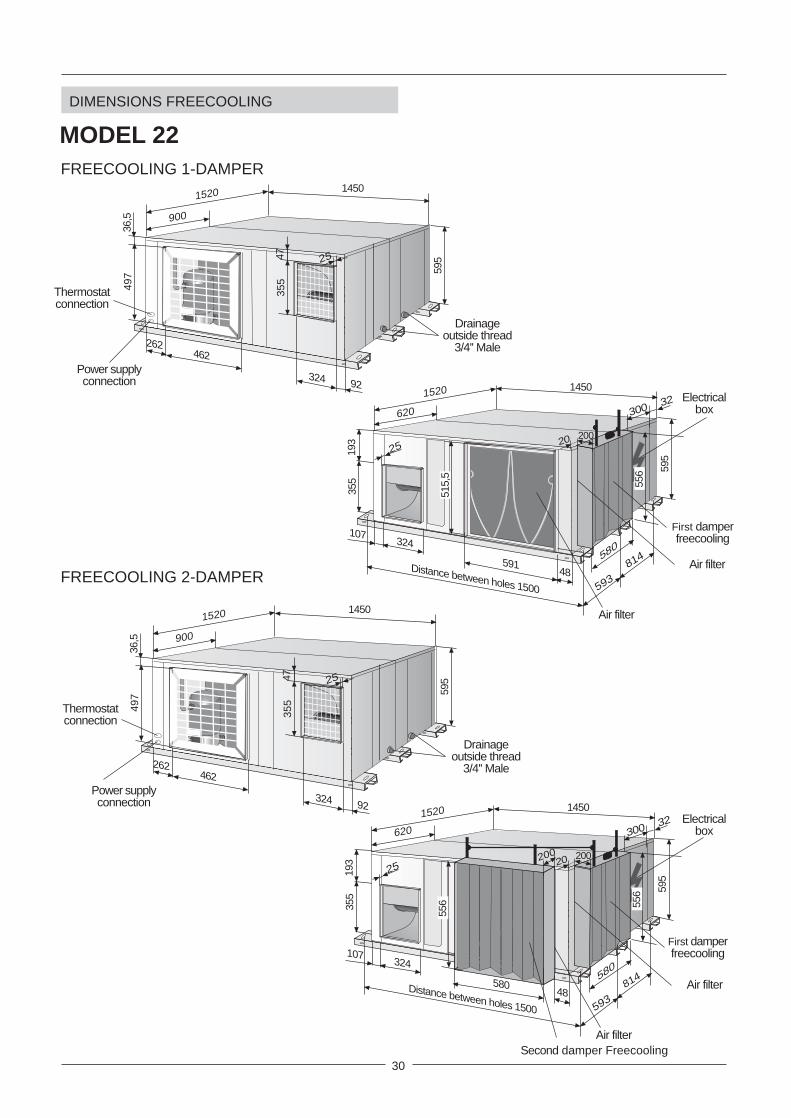
DIMENSIONS FREECOOLING
MODELS 10-12
81455
28090
159
303
Distance between holes 1300
F
734
404
480
25
455
Air filter
First damperfreecooling
480
200
FREECOOLING 1-DAMPER
FREECOOLING 2-DAMPER
F
734
404
480
25200
455
Second damperfreecooling
Air filter
First damperfreecooling
480
184452
425
32
1250
495
Drainageoutside thread
3/4'' Male
Electrical box
1250
820
349
303
305
Thermostat connection
Power supply connection123
20
27
25
184452
425
32
1250
495
Drainageoutside thread
3/4'' Male
Electrical box
1250
820
349
303
305
123
20
27
Thermostat connection
Power supply connection
25
200

29
DIMENSIONS FREECOOLING
MODEL 16
249422
500
32
1300
595
Drainageoutside thread
3/4'' Male
Electrical box
1330
830
324
355
320
Thermostat connection
Power supply connection
123
20
27
25
147455
32498
182
355
Distance between holes 1350
F
745
474
586
25200
23
455
Second damperfreecooling
Air filter
First damperfreecooling
586
200
249422
500
32
1300
595
Drainageoutside thread
3/4'' Male
Electrical box
1330
830
324
355
320
Thermostat connection
Power supply connection
123
20
27
25
147455
32498
182
355
Distance between holes 1350
F
745
474
586
25 23
455
Air filter
First damperfreecooling
586
200
FREECOOLING 1-DAMPER
FREECOOLING 2-DAMPER
30
DIMENSIONS FREECOOLING
MODEL 22
1450
324107
193
355
595
Distance between holes 1500
Air filter
25
F
1520
620
814
593
Air filter
300 32 Electricalbox
25200
First damperfreecooling
48591
515,
520
580
556
262462
497
36,5
1450
595
Drainageoutside thread
3/4'' Male
Thermostatconnection
Power supplyconnection
1520
900
324 92
4735
5
25
1450
324107
193
355
595
Distance between holes 1500
Air filter
25
F
1520
620
814
593
Air filter
300 32 Electricalbox
25200
Second damper Freecooling
48580
200
556
20
580
First damperfreecooling
556
262462
497
36,5
1450
595
Drainageoutside thread
3/4'' Male
Thermostatconnection
Power supplyconnection
1520
900
324 92
4735
5
25
FREECOOLING 1-DAMPER
FREECOOLING 2-DAMPER

31
DIMENSIONS FREECOOLING
MODELS 24-28-30
490398
1500
645
410Electrical box
Drainageoutside thread
3/4'' Male
1800
1025
Thermostatconnection
Power supplyconnection
103
2535
521
4
1500
56705
32795
223,
535
5
645
Distance between holes 1550
2525
1800
Air filter
677775
641 53
7
20083
705First damperfreecooling
Second damper freecooling
771916
200
490398
1500
645
410Electrical box
Drainageoutside thread
3/4'' Male
1800
1025
Thermostatconnection
Power supplyconnection
103
25
355
214
1500
82658
32795
223,
535
5
645
Distance between holes 1550
2525
1800
Air filter
677775
565,
4 537
83
705First damperfreecooling
771916
26 200
FREECOOLING 1-DAMPER
FREECOOLING 2-DAMPER

32
STANDARDBLOWEROPENING
OPTIONALBLOWEROPENING
A1A0
B0 B1
OUTDOOR SECTION
C1
D1
INDOOR SECTION
C0
D0
A0
A1
B0
B1
C1
C0
D0
D1
ELECTRICAL BOX
STANDARD EXECUTION
OPTIONAL EXECUTION
UNIT OPENING SIZES MODELS 10-12
1442
2
430 109
495
159
303
90 280
27430
422
E.B.
452 269
OUTDOOR COIL
COMPRESSOR
EXTERNALFAN
INTERNALFAN
INDO
OR
COIL
452184
E.B
.
170
90280
STANDARDEXTRACTOR
OPENING
OPTIONALBLOWEROPENING
303
349495
349
495
303
38
368
303
495
170
OPTIONALEXTRACTOR
OPENING
OPTIONAL AIRRETURNOPENING
STANDARDBLOWEROPENING
495
14
STANDARD AIRRETURNOPENING
425
495
425
495
123
43 43
495

33
A1A0
C1
D1
C0
D0
B0 B1
UNIT OPENING SIZES MODEL 16
2551
7
500 125
595
182
355
98 324
213
500
517
ELECTRICAL BOX
STANDARD CONFIGURATION
OPTIONAL CONFIGURATION
OUTDOOR COIL
COMPRESSOR
OUTDOORFAN
INDOORFAN
INDO
OR
COIL
E.B
.
A0
A1
B0
B1
C1
C0
D0
D1
98324
355
324
595
324
595
355
58
428
355
27
595
123
595
213
500
595
500
595
63 63
595
25
E.B.
422 304422249
STANDARDEXTRACTOR
OPENING
OPTIONALBLOWEROPENING
OPTIONALEXTRACTOR
OPENING
OPTIONAL AIRRETURNOPENING
STANDARDBLOWEROPENING
STANDARD AIRRETURNOPENING
STANDARDBLOWEROPENING
OPTIONALBLOWEROPENING
OUTDOOR SECTION
INDOOR SECTION

34
STANDARDBLOWEROPENING
OPTIONALBLOWEROPENING
A0
A1
B0
B1
C1
C0
D0
D1
A1A0
C1
D1
C0
D0
ELECTRICAL BOX
STANDARD EXECUTION
OPTIONAL EXECUTION
B0 B1
OUTDOOR SECTION
INDOOR SECTION
UNIT OPENING SIZES MODEL 22
2651
5,5
591 42,5
595
193
355
107 324
59115
193
E.B
.
OUTDOOR COIL
COMPRESSOR
EXTERNALFAN
INTERNALFAN
INDO
OR
COIL
462 384462262
107324
OPTIONALBLOWEROPENING
355
324
595
324
595
355
391,5
355
595
OPTIONAL AIRRETURNOPENING
STANDARDBLOWEROPENING
515,
5
595
26
STANDARD AIRRETURNOPENING
92
595
193
STANDARDEXTRACTOR
OPENING
OPTIONALEXTRACTOR
OPENING
497
595
497
595
61 61
193

35
STANDARDBLOWEROPENING
OPTIONALBLOWEROPENING
A1A0
B0
OUTDOOR SECTION
C1
D1
INDOOR SECTION
C0
D0
ELECTRICAL BOX
STANDARD EXECUTION
OPTIONAL EXECUTION
B1
(*) ONLY AVAILABLE WHEN UNIT ISDELIVER ON SPLIT SYSTEM
A0
A1
B0
C1
C0
D0
D1
E.B
.
A0
A1
B0
E.B.
COMPRESSOR
CO
IL
B1
UNIT OPENING SIZES MODELS 24-28-30
2656
5,5
658 82
645
223
355
95 327
658107
213
677 222 677
OUTD
OO
R CO
IL
COMPRESSOR
EXTERNALFAN
INTERNALFAN
INDO
OR
COIL
EXTERNALFAN
174
258327
STANDARDEXTRACTOR
OPENING
OPTIONALBLOWEROPENING
355
410645
410
645
355
355
645
OPTIONAL AIRRETURNOPENING
STANDARDBLOWEROPENING
565,
5
645
26
STANDARD AIRRETURNOPENING
537
4064
5
645
214
214103
103
OPTIONALEXTRACTOROPENING (*)
537
645
68

36
The bedplate is made up of three galvanized metal channels, capable of withstanding the weight of the unitswhether hung from the ceiling or mounted on the floor.If the unit is floor mounted, then should be isolated with shock absorbing material such as anti-vibration or pads.If used, consult the weight distribution table below to make the correct selection. Keep in mind that fans rotate atapproximately 850 rpm.If the unit is hung, M-10 threaded rods should be used along with shock absorbing ceiling supports.
UNIT HUNG WITH RODS UNIT INSTALLED ON SHOCK ABSORBERS
UNIT LOCATION AND WEIGHT DISTRIBUTION
Ceiling supports(shock absorbers)
G POINT: Centre of gravity
TABLE 1:
WEIGHT DISTRIBUTION
AND CENTRE OF
GRAVITY COORDINATES
UNIT INSTALLATION
Outdoor Sec.
Y
X
Outdoor Sec.
Y
X
MODELS 10-12-16-22 MODELS 24-28-30
Floor supports(shock absorbers)
WEIGHT DISTRIBUTION (Kg)
10
12
16
22
24
28
30
A B C D E F Total
35 65 10 20 40 35 205
35 65 15 20 40 35 210
70 60 15 30 80 30 285
Model
Point
80 70 20 40 75 45 330
90 100 15 65 85 55 410
95 110 20 65 85 55 430
95 110 25 70 80 55 435
CENTRE OF GRAVITYCOORDINATES (G) (mm.)
XG
585 590
565 615
630 600
710 685
760 815
715 825
705 825
YG
Fan.Comp.
Coil
B E
A
F
G
Fan.Coil
C D Indoor Sec.
XG
YGFan.
Comp.
B E
A
F
G
Fan.Coil
C D Indoor Sec.
XG
YGCoil

37
FREE SPACE FOR INSTALLATION
Clearance around the unit for service and maintenance.
For the unit with optional FREECOOLING, it should be kept in mind that the bedplate anchorscannot be used to hang the unit.Consult others options for outdoor mounting or changes in position of the air return duct if the unitis to be hung.
If the unit is going to be hung using the anchor supports and the optional air return opening, thesupports must be repositioned so that the air filter may be removed.To move the supports, unscrew them from the inside and fix them again using the holes locatednext to the initial position.
UNIT INSTALLATION
Trap
Drain pipe
DRAINS
All indoor sections of these units ( and the outdoors section for the Heat Pump) have a ¾” steel threaded drainpipe welded to the condensation tray.
One PVC drain trap is supplied with the cooling-only units, and two with the heat pump units.Connect the trap/s to the drain pipe/s on the unit and mount the drain pipe with at least a 2% incline from the trap.Also slightly tip the unit (2%) toward the drainage side. Check the condensation trays are clean and free from dirtand other debris from the works and that water drains correctly.
1 meter
1 meter 1 meter
1 meter
2%2%

38
PLACEMENT A : In gas pipe line is 1 necessary to install on vertical base a trap as well as a trap in the upper base each 8m. The minimum speed suction must be below 6m/s.PLACEMENT B : Do the cooling line pipe inclination to the outdoor unit. Pay attention in distance of more than 10m and avoid collapse on pipe lines installation.PLACEMENT C : It is necessary to install on the base pipe a vertical trap. It is not necessary intermediate trap.
PIPE CONNECTIONS
To determine the pipe connections between outdoor and indoor units follow data:
A,B,C : Placement units L : Total length. 1 = Gas pipe line. 2 = Liquid pipe line.
Between length of 30 and 50m superior you have to make a recalculation according to our technicalcommercial department or distribution itself to maintain certain aspects how to make the installation(additional charge of oil, solenoid valves etc...)
OUTDOOR UNIT
L
INDOOR UNITB2%
21
L
OUTDOOR UNIT
INDOOR UNIT
1
2
A
2%
2%
L
OUTDOOR UNIT2
1
INDOOR UNIT
C
2%
2%
- IN EACH CASE THE GAS PIPE MUST BE ISOLATED.- THE HORIZONTAL PIPE MUST HAVE AN INCLINATION OF 2 % TO THE OUTDOOR UNIT.- THE MAXIMUM SPEED ON LINE CAN BE SUPERIOR OF 15m/seg.
UNIT - MODEL
Liquid
Total line length
0 to 10 m.Gas
10 to 30 m. 5/8"
11/8"
5/8''
11/8"
3/4''
13/8"
5/8"3/8" 3/8" 5/8"
7/8"Gas
Liquid
7/8"7/8" 11/8"
24 28 302210 12 16
30 to 50 m.
11/8"7/8"Gas
Liquid 1/2" 1/2" 5/8" 5/8" 3/4'' 3/4'' 3/4''
7/8" 11/8" 13/8" 13/8" 13/8"
Unit connectionsLiquid
5/8"
11/8"
5/8''
11/8"
5/8''
11/8"
5/8"
7/8"
3/8"
3/4"
3/8"
3/4"
1/2"7/8"
5/8" 5/8'' 5/8''5/8"3/8" 3/8" 1/2"
PIPES LINE
Gas 11/8" 11/8" 11/8"7/8"3/4" 3/4" 7/8"
15 15 15 15 15 15 15Maximum vertical line length (m.)
TABLE 2: SELECTION ON PIPE LINES
12 12 12 12 12 12 12Maximum number of bends

39
Electricalbox
ElectronicCard
ELECTRICAL CONNECTION
VOLTAGE OPERATING LIMITS MODELS VOLTAGE LIMIT
10
10-12-16-22
24-28-30
230 V-1Ph-50Hz
230 V-3Ph-50Hz
230 V-3Ph-50Hz
400 V-3Ph-50Hz
400 V-3Ph-50Hz
198-264 V -1Ph- 50Hz
180-242 V -3Ph- 50Hz
342-462 V -3Ph- 50Hz
198-264 V -3Ph- 50Hz
342-462 V -3Ph- 50Hz
5 x 1,5
5 x 1,5
5 x 1,5
4 x 2,5 + 2 x 1
4 x 1,5 + 2 x 1
5 x 1,5
4 x 2,5 + 2 x 1
4 x 1,5 + 2 x 1
4 x 2,5 + 2 x 1
4 x 2,5 + 2 x 1
4 x 2,5 + 2 x 1
4Indoorunit 1
5 x 1,5
4 x 1,5 + 2 x 1
4 x 1,5 + 2 x 1
4 x 1,5 + 2 x 1
2
The sections have been calculated for a length no longer than 50m and a voltage drop of 10V.
4UNIT
MODEL
10
ShieldedCable
1
3 x 4 2 x 13 x 16
16
12
22
10
24
30
28
4 x 4
4 x 4
4 x 6
4 x 10
4 x 10
4 x 10
4 x 16
2 x 1
2 x 1
2 x 1
2 x 1
2 x 1
2 x 1
2 x 1
4 x 10
4 x 16
4 x 10
4 x 16
4 x 25
4 x 25
4 x 25
POWER SUPPLY 230V THREE-PHASE
UNITS
16
12
22
10
24
30
28
5 x 2,5
5 x 2,5
5 x 4
5 x 4
5 x 4
5 x 4
5 x 6
2 x 1
2 x 1
2 x 1
2 x 1
2 x 1
2 x 1
2 x 1
5 x 4
5 x 6
5 x 4
5 x 10
5 x 10
5 x 10
5 x 10
POWER SUPPLY400V THREE-PHASE
UNITS
1
POWER SUPPLY 230V SINGLE-PHASE
UNITS 2
4Shielded
Cable
1 1 2
4Shielded
Cable
1 1 2
thermostatcontrol
Electrical supply.Connection indoor / outdoor unit.Electrical heater power supply.Connection thermostat control.
12
43
3
PE L1 L2 L3 N X1
3N ~ 400V - 50 Hz + PE
UNITMODEL
UNITMODEL
4 x 4 + 2 x 1
4 x 4 + 2 x 1
4 x 4 + 2 x 1
4 x 4 + 2 x 1
4 x 4 + 2 x 1
4 x 4 + 2 x 1
4 x 4 + 2 x 1
3 x 4 + 2 x 1
4 x 2,5 + 2 x 1
4 x 2,5 + 2 x 1
4 x 2,5 + 2 x 1
4 x 2,5 + 2 x 1
4 x 2,5 + 2 x 1
4 x 2,5 + 2 x 1
4 x 2,5 + 2 x 1
3
3
3
Nr. OF CABLES x SECTION (mm )2
Nr. OF CABLES x SECTION (mm )2
Nr. OF CABLES x SECTION (mm )2
Outdoorunit
PE L1 L2 X1L3
3 ~ 230V - 50 Hz + PE
Power supplyWITHOUT
electrical heater.
Power supplyWITH electrical
heater.
PE N L X1
1N ~ 230V - 50 Hz + PE
Connectionoutdoor-indoor unit
WITHOUTelectrical heater.
Power supplyWITHOUT
electrical heater.
Power supplyWITH electrical
heater.
Power supplyWITHOUT
electrical heater.
Power supplyWITH electrical
heater.
Connectionoutdoor-indoor unit
WITHOUTelectrical heater.
Electrical heaterpower supply
Electrical heaterpower supply
Electrical heaterpower supply
Connectionoutdoor-indoor unit
WITHOUTelectrical heater.

40
OPERATING LIMITS
INDOORTEMPERATURE
MAXIMUM TEMPERATURES MINIMUM TEMPERATURES
32ºC DB / 23ºC WBCOOLING CYCLE
OPERATION
21ºC DB / 15ºC WB
OUTDOORTEMPERATURE
0ºC (MODELS 22/24/28/30)19ºC (MODELS 10/12/16) (*)
-10ºC(**)
INDOORTEMPERATURE
MAXIMUM TEMPERATURES MINIMUM TEMPERATURES
32ºC DB / 23ºC WB 21ºC DB / 15ºC WB
OUTDOORTEMPERATURE
INDOORTEMPERATURE 27ºC DB 15ºC DB
OUTDOORTEMPERATURE 24ºC DB / 18ºC WB -10ºC DB / -11ºC WB
0ºC (MODELS 22/24/28/30)19ºC (MODELS 10/12/16) (*)
-10ºC(**)
COOLING CYCLEOPERATION
HEATING CYCLEOPERATION
OPERATING LIMITS FOR (COOLING ONLY) UNITS
OPERATING LIMITS FOR (HEATING PUMP) UNITS
DB.- Dry Bulb TemperatureWB.- Wet Bulb Temperature
(*) With condensation pressure control (optional), 0ºC minimum outdoor operating temperature.(**) With kit got gas bypass valve.
DEPENDING ON MODEL(TABLE 1)
TABLE 1- COOLING CYCLE MAXIMUM OUTDOOR OPERATING TEMPERATURES
MODELS
Rated outdoor flow
Minimum outdoor flow
10 12 16 22 24 28 30
MODELS WITH REFRIGERANT R-407C
45
43
43
43
44
41
45
41
46
42
42
39
41
38
MODELS
Rated outdoor flow
Minimum outdoor flow
10 12 16 22 24 28 30
MODELS WITH REFRIGERANT R-22
48
46
48
45
47
45
48
46
48
44
46
42
44
40
(*) With condensation pressure control (optional), 0ºC minimum outdoor operating temperature.(**) With kit got gas bypass valve.
DEPENDING ON MODEL(TABLE 1)

41
ELECTRIC HEATEROptionally, these units can contain shielded element electric heating batteries that are mounted on the inside of the unit in the schematicopposite.The electric heater must get its power from the unit’s electrical box.
PROTECTION AGAINST FREEZING:• Use glycol water. GLYCOL IS THE ONLY EFFECTIVE PROTECTION AGAINST FREEZING.• Regulation components should be used and in addition security components if they are needed.• Drain the installation. You must ensure that the manual or automatic air vents have been installed on all high points in the system.In order to drain the system check that all the drain cocks have been installed on all low points of the system.
MAIN SWITCHThe main switch is located on the access panel to the electrical box in the outdoor section in such a way that the unit is disconnectedwhen the panel is opened.(Refer to the size diagram a pages 20 to 31 to see the position of the electrical box access panel).Check to make sure that the main switch is large enough to handle the current for the unit if electric heaters are installed.PHASE SEQUENCER (THREE-PHASE UNIT)The phase sequencer is located in the electrical box in the outdoor section, thus assuring that the unit will not begin operation whilethe phase connection of the compressor is not correct. Should this occur, then just switch two phase connections.ON/OFF CONDENSATION PRESSURE CONTROL (MODELS 10-12-16)Consists of a pressure switch, which starts and stops the outdoor fan regulating the condensation temperature, thus the unit will beable to operate in the cooling cycle when the outdoor temperature is below 19ºC (until 0ºC).HOT GAS BYPASS VALVEThe purpose of the BYPASS valve is to make it possible for the unit to operate at low outdoor temperatures (until -10°C), to be usedin cooling-only and heat-pump units in the cooling cycle.It regulates the capacity of the compressor by injecting hot gas from the compressor discharge side to the evaporator.CONTROL USING A PROGRAMMABLE CONTROLLER.With the programmable controller option, the desired temperature can be programmed in the area 24 hours a day, 7 days a week.REMOTE ROOM-TEMPERATURE SENSOR, REMOTE DUCT SENSORThese sensors may be used in conjunction with remote controller, allowing the controller to be mounted in a room away from theconditioned space.- REMOTE DUCT SENSOR: The sensor will be located in the return air duct, detecting the air temperature of the air being air conditioned.- REMOTE ROOM-TEMPERATURE SENSOR: The sensor will be placed in the area to be air conditioned.FREECOOLING THERMOSTAT KITThe Freecooling Thermostat Kit will only operate in cooling-only or heat-pump units in the cooling cycle. This is an energy savingsystem that regulates the dampers doors through which outdoor air is taken in when the outdoor temperature is lower than the areato be air conditioned.This kit consists of the damper, a motor, power card and a controller with specific programming, safety thermostat for air dischargeand outdoor sensor, completely factory-assembled.CRANKCASE HEATER (COOLING-ONLY UNITS)When the unit is operating at low outdoor temperatures it is advisable to fit a crankcase heater.The purpose of the heater is to keep the oil in the compressor at the correct temperature while the compressor is stopped so that itcan be properly lubricated when started again.
HOT WATER COILIt is based on a refrigerating coil made of copper tubing with aluminum swirl fins withwater inlet and outlet connections.It is supplied mounted inside the unit as picture shows.
OPTIONS
DIFFERENCE IN TEMPERATURESBETWEEN HOT WATER INTAKEAND THE AIR WHICH ENTERS
THE COIL
50ºC 60ºC 70ºC
WATERFLOW
L/H
WATER COILPRESSURE
DROP kPa
AIRPRESSURE
DROPPa
10-12CAPACITY IN W
CAPACITY IN W
CAPACITY IN W
9000 11000 12800
15000 18000 21000
24500 29500 34400
500
1000
1500
0,5
1,5
3
35-30
30-25
25-20
22
24-28-30
16CAPACITY IN W
14500 17500 20400 1000 1,5 35-30
NrROWS
2
2
2
2
WEIGHT
Kg
4
6
7
5
WATEROUTLET
DIAMETERInches
3/4"
3/4"
3/4"
3/4"
MODELSFLC/FLH
INDOOR UNITnominal-minimum
air flow
A HEATING COIL FROZEN DUE TO LOW AMBIENT CONDITIONS IS NOT COVERED BY THE WARRANTY.
22,7
MODELS LFXO 10
MAXIMUMCURRENT
(A) 230 / III400 / III
POWER kW12-16-22
7WEIGHTS Kg (*)STAGES 1 1
6
15,18,7
9
13,17
24-28-30
81
7,5
18,910,9
12
30,217,4
6
15,18,7
9
22,713,1
230 / I ---- ---- ---- ----26,1 ----
(*) Add to the unit's weight.

42
OPTIONS
SOUND MUFFLERAvailable for models 16, 22, 24, 28, 30.Field assembled, designed to be installed at the extractor opening of the outdoorunit in order to reduce noise, particularly when the outdoor unit is installed withoutducts, free discharge.This kit contains the sound muffler and adapter parts for fixing it to the unit.
OUTDOOR MOUNTING KITField assembly.This option has to be ordered for packaged units when they will be installed outside.The kit includes an air filter and grille for outdoor air intake which should be installed on the suction side of the outdoor unit, an anti-rain hood which should be installed on the discharge side of the outdoor fan. For units 10-12-16 it includes also an anti-rain platewhich should be installed on the electrical box.
OUTDOOR AIR FILTER KITField assembly.The outdoor air filter should be installed on the outdoor air inlet of the outdoor unit and is recommended when working in heavilycontaminated area that may soil or clog the outdoor Coil.
FREECOOLING EXTERNAL MOUNTED KITField assembly.This option has to be ordered for packaged units with freecooling when they will be installed outside, it includes:- FREECOOLING 1-DAMPER: It includes an outdoor air inlet grille to cover damper and actuator.- FRECOOLING 2-DAMPER: It includes an anti-rain cap to cover return air damper.
ADDITIONAL DROP CHARGE FORSOUND MUFFLER (OPTIONAL)
ADDITIONAL DROP CHARGE FORSOUND MUFFLER (OPTIONAL)
+OUTDOOR AIR FILTER (OPTIONAL)
ADDITIONAL DROP CHARGE FOREXTERNAL AIR FILTER (OPTIONAL)
Nominal flowMinimum flowMax. available pressurefor minimum flow
30 Pa10 12 16 22 24 28 30
MODELS
30 Pa 30 Pa 30 Pa 30 Pa 30 Pa 30 Pa25 Pa 25 Pa 25 Pa 25 Pa 25 Pa 25 Pa 25 Pa
75 Pa 65 Pa 95 Pa 125 Pa 145 Pa 95 Pa 75 Pa
Nominal flowMinimum flowMax. available pressurefor minimum flow
25 Pa16 22 24 28 30
MODELS
60 Pa 80 Pa 75 Pa 75 Pa20 Pa 45 Pa 70 Pa 60 Pa 60 Pa
95 Pa 90 Pa 95 Pa 45 Pa 25 Pa
Nominal flowMinimum flowMax. available pressurefor minimum flow
55 Pa16 22 24 28 30
MODELS
90 Pa 110 Pa 105 Pa 105 Pa40 Pa 70 Pa 95 Pa 85 Pa 85 Pa
65 Pa 45 Pa 25 Pa 20 Pa 0 Pa
Adapter partsSound muffler
600
41
660
420
660
400
Anti-rain plate(only models 10-12-16)Anti-rain hood
Outdoor air intake
Air filter
C
B
AF
G
D
E
MODELS
10-12A
180
16 180
22 180
24-28-30 180
B432
507
505
544
C459
429
470
685
D280
311,8
304,9
304,9
E313
364
363
363
F356
330
332
418
G104
104
96,5
96,5
DIMENSIONS
External mounted freecooling 1-damper
External mounted freecooling 2-damper
I
H G
F
C B
A
E
D
MODELS
10-12A
200
16 200
22 200
24-28-30 200
B465
460
600
712
C400
600
600
600
D635
723
708
784
E187,4
163
187,5
187,5
F162
174
159
158,5
G192
192
192,5
191
H461
456
592
706
I153
174
159
158,5
DIMENSIONS

www.lennoxeurope.com
www.lennoxbelgium.com
www.lennoxczech.com
www.lennoxfrance.com
www.lennoxdeutschland.com
www.lennoxnederland.com
www.lennoxpolska.com
www.lennoxportugal.com
www.lennoxrussia.com
www.lennoxdistribution.com
www.lennoxspain.com
www.lennoxukraine.com
www.lennoxuk.com
www.lennoxdistribution.com
MSL60E-0701 12-2006
BELGIUM, LUXEMBOURG
CZECH REPUBLIC
FRANCE
GERMANY
NETHERLANDS
POLAND
PORTUGAL
RUSSIA
SLOVAKIA
SPAIN
UKRAINE
UNITED KINGDOM AND IRELAND
OTHER COUNTRIES
Due to Lennox’s ongoing commitment to quality,
the Specifications, Ratings and Dimensions are
subject to change without notice and without
incurring liability.
Improper installation, adjustment, alteration,
service or maintenance can cause property
damage or personal injury.
Installation and service must be performed by a
qualified installer and servicing agency.