application guide - littelfuse.com/media/protection-relays/application-guides/littelfuse... ·...
TRANSCRIPT
APPLICATION GUIDE
AF0500ARC-FLASH
RELAY
AF0500 Arc-Flash Relay
APPLICATION GUIDE
2 Littelfuse.com/ArcFlash© 2016 Littelfuse Products
Table of Contents
1 INTRODUCTION ........................................................................................................................................................3
1.1 Arc-Flash Relay ......................................................................................................................................................3
1.2 Optical Sensors .....................................................................................................................................................3
2 DESIGN .......................................................................................................................................................................4
2.1 Typical Arc-Flash Protection Applications .............................................................................................................4
2.2 Arcing Faults .........................................................................................................................................................5
2.2.1 Typical Energy in an Arcing Fault .................................................................................................................5
2.2.2 Arc-Flash Relays and PPE ............................................................................................................................5
2.3 Electrical Drawings ...................................................................................................................................................6
2.3.1 AF0500 Arc-Flash Relay Back Plate and Sensor Dimensions .....................................................................6
2.3.2 Connections .................................................................................................................................................6
2.3.3 Symbols .......................................................................................................................................................6
3 INSTALLATION ..........................................................................................................................................................7
3.1 Block Diagram ......................................................................................................................................................7
3.2 Relay Placement ...................................................................................................................................................7
3.2.1 Maximum Distance to Circuit-Breaker .........................................................................................................7
3.2.2 Maximum Distance to Sensors ...................................................................................................................8
3.3 Redundant Trip Path..............................................................................................................................................9
3.4 Sensor Placement .................................................................................................................................................9
3.4.1 Point Sensor Placement ...............................................................................................................................10
3.4.2 Fiber-Optic Sensor Placement .....................................................................................................................11
4 EXAMPLES .................................................................................................................................................................12
4.1 Zone Tripping .........................................................................................................................................................12
4.2 Tripping of an upstream circuit breaker in case of clearing failures on the local circuit breaker ...........................14
4.3 Mains-Tie-Mains Application ................................................................................................................................16
APPENDIX A: SUPPORTING MATERIALS..................................................................................................................18

AF0500 Arc-Flash Relay
APPLICATION GUIDE
3 Littelfuse.com/ArcFlash© 2016 Littelfuse Products
180˚ 2-meter Half-Sphere
Sensor Viewing Angle
1 INTRODUCTION
1.1 Arc-Flash Relay
The AF0500 is a microprocessor-based protection relay that limits arc-flash damage by using light sensors to rapidly detect the arc and then trip a circuit breaker. Sensors, inputs, and trip-coil voltage are monitored to ensure fail-safe operation. A secondary solid-state circuit provides a redundant trip path. A USB port is used for configuration and access to event logs.
The AF0500 can be used on electrical systems operating at any voltage (AC or DC) since it does not directly connect to the system. The small size of the AF0500 allows installation in any switchgear cubicle, transformer compartment, or motor control center bucket.
1.2 Optical Sensors
The AF0500 accepts PGA-LS10 (point), PGA-LS20, and PGA-LS30 (fiber) optical sensors. These sensors have been designed to have a wide detection angle and provide the correct sensitivity for an arc flash. LEDs on the relay and on the sensors indicate sensor health and which sensor(s) detected an arc fault. All sensor types include an optical-to-electrical transducer and connect to the AF0500 with copper wire.
PGA-LS10: Detection Range of a 3 kA Arcing Fault
Point Sensor (PGA-LS10)The point sensor has a detection area of a 2 m half-sphere for arcs of 3 kA or more. Each PGA-LS10 features a built-in LED which enables an AF0500 to verify the function of the light sensor, wiring, and electronics. If the relay does not detect the sensor-check LED, a sensor-fail alarm will occur; the ONLINE output will change state, the ONLINE LED will begin to flash, and the sensor LED will show short red flashing. The sensor includes 10 m of shielded three-wire electrical cable which can easily be shortened or extended to a maximum of 50 m.
Fiber-Optic Sensor (PGA-LS20, PGA-LS30)The fiber-optic sensor has a 360° detection zone along the fiber’s length (8 m for the PGA-LS20, 18 m for the PGA-LS30). Each PGA-LS20 and PGA-LS30 features a built-in LED which enables the AF0500 to verify the function of the fiber-optic light sensor, wiring, and electronics. If the relay does not detect the sensor-check LED, a sensor-fail alarm will occur; the ONLINE output will change state, the ONLINE LED will begin to flash, and the sensor LED will show short red flashing.
The fiber-optic sensors have three components: 1. A fiber-optic cable bundle terminating on both ends, one end
covered with a black sleeve, and the other is uncovered. Both ends are terminated at the factory.
2. A transmitter with a white enclosure and a white thumb nut.3. A receiver with a white enclosure, a black thumb nut, and an adjustment screw behind an access hole. Both the receiver and the transmitter connect to a single input on the AF0500 using shielded three-wire electrical cable. The receiver and transmitter each include 10 m of shielded three-wire electrical cable that can easily be shortened or extended to a maximum of 50 m. All three components are monitored to ensure continuity and correct operation.
Light Sensor
2m
2.5m
Up to 50 m cable
PGA-LS20: Active Length of 8 mPGA-LS30: Active Length of 18 m
Up to 50 m cables
Receiver
Black Shield (no light detection)
Transmitter

AF0500 Arc-Flash Relay
APPLICATION GUIDE
4 Littelfuse.com/ArcFlash© 2016 Littelfuse Products
Fiber
The fiber is the light-collecting element of the PGA-LS20 and PGA-LS30. It must be installed so it has line-of-sight to all current-carrying parts. In some cases this may be accomplished by mounting in a position that follows the bus bars along the back wall of the cabinets.
Connect the black-sleeve-covered end to the receiver using the black thumb nut, and the white uncovered end to the transmitter using the white thumb nut. Ensure the fiber is inserted completely into the transmitter and receiver and the nuts are tightened. Pull gently on the electrical cable to verify a secure connection.
The fiber should not be sharply bent or pinched. The minimum bending radius is 5 cm.
Point or Fiber-Optic Sensors?
The AF0500 supports two types of arc-flash sensors, point sensors (PGA-LS10) and fiber-optic sensors (PGA-LS20 and PGA-LS30). Both sensor types gather light and transmit the intensity of the light back to the AF0500. The point sensor monitors the light from a single collection point while the fiber-optic sensors collect light along their entire length. The decision to use point sensors or fiber-optic sensors comes down to the geometry of the equipment to be monitored and the importance of fault location. In a switchgear installation with many small cabinets, it may be more cost-effective to pass a single fiber-optic sensor through all the cabinets than to install one point sensor per cabinet. However, this is done at the expense of using the fault location features of the AF0500 to determine the location of the arc-flash within those cabinets, not which sensor sees the fault. Sensor types can be combined to further customize the solution. An understanding of the two sensor types and their properties is important for selecting the correct sensors.
2 DESIGN
2.1 Typical Arc-Flash Protection Applications Although an arc flash is improbable on systems operating at 208 V or less, systems with higher voltages have sufficient capacity to cause an arc flash and should use proper protection. Arc-flash protection is especially important in the following applications:
g Solidly grounded electrical distribution systems: It is estimated that over 95% of all electrical faults are, or begin as, a ground fault.* Ground-fault current on a solidly grounded system is only limited by the resistance of the fault and system impedance, and has the potential to cause an arc flash.
g Air-cooled transformers: On air-cooled equipment, the winding insulation, terminals, and ground points are exposed to the environment. Pollution, dust, and other contaminants can cause premature insulation failure and can lower the resistance of the air gap between energized conductors, and between energized conductors and ground. Insulation failure and lower air-gap resistance increase the probability of an arc flash.
g Rack-out breakers: As a circuit breaker is racked out, there is a potential for an arc flash to develop when the electrical contacts are disconnected while energized.
g Non-insulated bus.g Ungrounded and resistance-grounded system: Systems that are alarm only, and don't remove faults in a
timely fashion.g Devices with high inrush currents: Transformers, capacitor-banks, surge arrestors, large motors, and other
reactive loads will cause a high-inrush current when energized. To allow these systems to operate properly, instantaneous-current settings on circuit breakers will either be set very high or not used, allowing an arc-flash to remain on the system for longer, or not be detected at all.
g Medium and high-voltage equipment: Medium-voltage equipment (4160 V and higher) often uses air insulation.
*Source: Industrial Power System Grounding Design Handbook by J.R. Dunki-Jacobs, F.J. Shields, and Conrad St. Pierre, page xv.
AF0500 Arc-Flash Relay
APPLICATION GUIDE
5 Littelfuse.com/ArcFlash© 2016 Littelfuse Products
g Moveable and mobile electrical equipment: Mobile electrical equipment is subject to physical damage while in motion and has a higher potential for an arc flash. The designs are often more compact, reducing air gap insulation levels.
g Areas where work or maintenance is regularly performed on energized equipment: While maintenance personnel are required to wear proper PPE when working on or around energized equipment, an arc-flash relay can be used to lower the levels of hazard that personnel are exposed to.
g Older facilities: Where often, room is not available for any other means of Arc-Flash Hazard mitigation.
2.2 Arcing Faults
2.2.1 Typical Energy in an Arcing Fault
A phase-to-phase fault on a 480-V system with 20,000 amperes of fault current provides 9,600,000 watts of power. Imagine that there is no arc protection and the fault lasts for 200 milliseconds before the overcurrent protection clears it. The released energy would be 2 MJ, which corresponds roughly to a stick of dynamite.
The energy formula is as follows:
Energy = voltage x current x time = 480 V x 20,000 A x 0.2 s = 1,920,000 J
For a given system voltage, two factors can be adjusted to reduce arc-flash energy: time and current
Time can be reduced by using a device such as the AF0500 to rapidly detect an arc flash, thus causing the connected circuit breaker to trip at its instantaneous speed, overriding any inverse-time delay. Current can be reduced by using current-limiting fuses or, in case of phase-to-ground faults, by using high-resistance grounding.
2.2.2 Arc-Flash Relays and PPE
Reducing the clearing time is typically a trade-off with system uptime for current-based protection. Sufficient delay is required to prevent unnecessary tripping on momentary overload or current spikes. Such delay limits how quickly such a system can react.
Arc-flash relays address this issue by detecting light rather than current, which permits a much faster response that is independent of current spikes and momentary overloads. The AF0500 relay can detect an arcing condition and send a trip signal to a circuit breaker in less than 1 ms. This response time is much faster than standard current-based protection, which means using an arc-flash relay will lower the incident energy or arc-flash hazard in most cases. This results in increased worker safety, less fault damage, and improved uptime.
If the arc-flash incident energy has decreased, the associated PPE requirement may also be lowered. The exact improvement will depend on the installation, so the AF0500 must be modeled in the system to determine the new incident energy and PPE.
AF0500 Arc-Flash Relay
APPLICATION GUIDE
6 Littelfuse.com/ArcFlash© 2016 Littelfuse Products
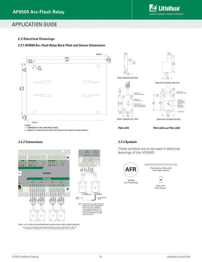
2.3 Electrical Drawings
2.3.1 AF0500 Arc-Flash Relay Back Plate and Sensor Dimensions
2.3.2 Connections 2.3.3 Symbols
These symbols are to be used in electrical drawings of the AF0500:
AFR
AF0500 Arc-Flash Relay
PGA-LS10 Point Sensor
PGA-LS20 or PGA-LS30 Fiber-Optic Sensor
PGA-LS10 PGA-LS20 and PGA-LS30
8.3
(0.3
3)
10 m
(32.
8 ft
)
9.6(0.38)
14.2(0.56)
23.8
(0.94)
44.0
(1.7
3)
24.0(0.94)
4.0(0.16)
RE
D
WH
ITE
YE
LLO
W
SH
IELD
/ B
LAC
K
2.4(0.09)
52.0
(2.0
5)
32.0(1.26)
Ø4.25(0.167)MOUNTING HOLES
Ø8.3(0.33)SENSOR LENS
RED LED FORCIRCUIT CHECK ANDVISUAL DIAGNOSTICS
8.00
(0.3
2)
NOTES: 1. UP TO 4 PGA-LS10 POINT SENSORS WITH BUILT-IN CIRCUIT CHECK CAN BE CONNECTED.
Ø4.25(0.167)MOUNTING HOLES
RECEIVERSENSITIVITYADJUSTMENTSCREW
DECREASESENSITIVITY
THUMB NUT
2.0(0.08)
46.0
(1.8
1)
18.8(0.74)
24.0(0.94)
4.0(0.16)
4.0(0.16)
42.0
(1.6
5)
46.0
(1.8
1)
32.0(1.26)
NOTE: THE PGA-LS20 AND PGA-LS30 SENSORS SHIP ASSEMBLED WITH A PLUG-IN TERMIAL. IT MAY BE NECESSARY TO DISCONNECT IT FROM THE PLUG-IN TERMINAL DURING INSTALLATION.
AF0500 Arc-Flash Relay
APPLICATION GUIDE
7 Littelfuse.com/ArcFlash© 2016 Littelfuse Products
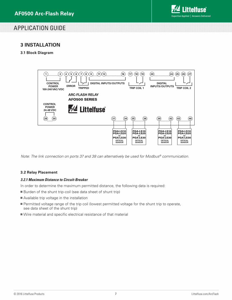
Note: The link connection on ports 37 and 38 can alternatively be used for Modbus® communication.
3 INSTALLATION
3.1 Block Diagram
28
1 3 9 4 12 16 24 20 25 26 27 7 8 5
30........
31 34..............
35 38..............
39 42..............
43 46..............
........ ...................... ..................................... 6 17 18 1911
TRIP COIL 2TRIP COIL 1TRIPPEDERROR
CONTROL POWER
100-240 VAC/VDC
CONTROL POWER
24-48 VDC
DIGITAL INPUTS/OUTPUTS DIGITAL INPUTS/OUTPUTS
ARC-FLASH RELAYAFO500 SERIES
PGA-LS10PGA-LS20
orPGA-LS30
OPTICALSENSOR
PGA-LS10PGA-LS20
orPGA-LS30
OPTICALSENSOR
PGA-LS10PGA-LS20
orPGA-LS30
OPTICALSENSOR
PGA-LS10PGA-LS20
orPGA-LS30
OPTICALSENSOR
3.2 Relay Placement
3.2.1 Maximum Distance to Circuit-Breaker
In order to determine the maximum permitted distance, the following data is required:g Burden of the shunt trip-coil (see data sheet of shunt trip)g Available trip voltage in the installationg Permitted voltage range of the trip coil (lowest permitted voltage for the shunt trip to operate,
see data sheet of the shunt trip)g Wire material and specific electrical resistance of that material
AF0500 Arc-Flash Relay
APPLICATION GUIDE
8 Littelfuse.com/ArcFlash© 2016 Littelfuse Products
3.2.2 Maximum Distance to Sensors
The maximum length of electrical cable between a PGA-LS10 point sensor and an AF0500 is 50 m.
The maximum length of electrical cable between a PGA-LS20/PGA-LS30 fiber-optic sensor and an AF0500 is 50 m to the transmitter module and 50 m to the receiver module.
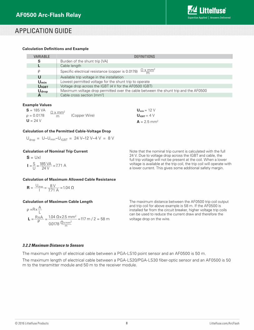
Calculation of the Permitted Cable-Voltage Drop
Udrop = U–Umin–UIGBT = 24 V–12 V–4 V = 8 V
Calculation of Nominal Trip Current
S = UxI
Note that the nominal trip current is calculated with the full 24 V. Due to voltage drop across the IGBT and cable, the full trip voltage will not be present at the coil. When a lower voltage is available at the trip coil, the trip coil will operate with a lower current. This gives some additional safety margin.
Calculation of Maximum Cable Length The maximum distance between the AF0500 trip coil output and trip coil for above example is 58 m. If the AF0500 is installed far from the circuit breaker, higher voltage trip coils can be used to reduce the current draw and therefore the voltage drop on the wire.
Calculation of Maximum Allowed Cable Resistance
Example ValuesS = 185 VAρ = 0.0178
Ω x mm2 m (Copper Wire)
U = 24 V
Umin = 12 VUIGBT = 4 V
A = 2.5 mm2
Calculation Definitions and Example
R = Udrop
I= 8 V
7.71 A= 1.04 Ω
I = SU
= 185 VA 24 V
= 7.71 A
ρ =Rx AL
L = RxAρ = 1.04 Ωx2.5 mm2
0.0178 Ωxmm2
m
=117 m / 2 = 58 m
VARIABLE DEFINITIONSS Burden of the shunt trip [VA]L Cable lengthρ Specific electrical resistance (copper is 0.0178)
U Available trip voltage in the installationUmin Lowest permitted voltage for the shunt trip to operateUIGBT Voltage drop across the IGBT (4 V for the AF0500 IGBT)Udrop Maximum voltage drop permitted over the cable between the shunt trip and the AF0500A Cable cross section [mm2]
Ω x mm2 m
AF0500 Arc-Flash Relay
APPLICATION GUIDE
9 Littelfuse.com/ArcFlash© 2016 Littelfuse Products
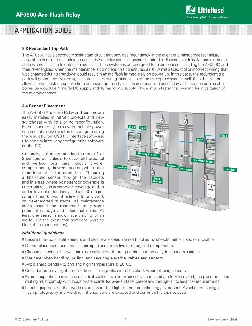
3.4 Sensor Placement
The AF0500 Arc-Flash Relay and sensors are easily installed in retrofit projects and new switchgear with little or no reconfiguration. Even elaborate systems with multiple power sources take only minutes to configure using the relay’s built-in USB PC-interface software. (No need to install any configuration software on the PC)
Generally, it is recommended to mount 1 or 2 sensors per cubicle to cover all horizontal and vertical bus bars, circuit breaker compartments, drawers, and anywhere that there is potential for an arc fault. Threading a fiber-optic sensor through the cabinets and in areas where point-sensor coverage is uncertain results in complete coverage and an added level of redundancy (at least 60 cm per compartment). Even if policy is to only work on de-energized systems, all maintenance areas should be monitored to prevent potential damage and additional costs. At least one sensor should have visibility of an arc fault in the event that someone were to block the other sensor(s).
Additional guidelinesg Ensure fiber-optic light sensors and electrical cables are not blocked by objects, either fixed or movable.g Do not place point sensors or fiber-optic sensor on live or energized components.g Choose a location that will minimize collection of foreign debris and be easy to inspect/maintain.g Use care when handling, pulling, and securing electrical cables and sensors.g Avoid sharp bends (<5 cm) and high temperature (>80°C).g Consider potential light emitted from air-magnetic circuit breakers when placing sensors.g Even though the sensors and electrical cables have no exposed live parts and are fully insulated, the placement and
routing must comply with industry-standards for over-surface (creep) and through-air (clearance) requirements.g Label equipment so that workers are aware that light detection technology is present. Avoid direct sunlight,
flash photography and welding if the sensors are exposed and current inhibit is not used.
3.3 Redundant Trip Path
The AF0500 has a secondary solid-state circuit that provides redundancy in the event of a microprocessor failure. Less often considered, a microprocessor-based relay can take several hundred milliseconds to initialize and reach the state where it is able to detect an arc flash. If the system is de-energized for maintenance (including the AF0500) and then re-energized when the maintenance is complete, this constitutes a risk. A misplaced tool or incorrect wiring that was changed during shutdown could result in an arc flash immediately on power up. In this case, the redundant trip path will protect the system against arc flashes during initialization of the microprocessor as well, thus the system allows a much faster response time on power up than typical microprocessor-based relays. The response time after power up would be 4 ms for DC supply and 40 ms for AC supply. This is much faster than waiting for initialization of the microprocessor.
Fiber-Optic Sensor
Fiber-Optic Sensor
Point Sensor
TransmitterReceiver
Tie Breaker
Source 1
Breaker
Transmitter Receiver
Source 2
Breaker
Trip 2
Trip 2
Trip 1
Trip 1
AF0500 Arc-Flash Relay
APPLICATION GUIDE
10 Littelfuse.com/ArcFlash© 2016 Littelfuse Products
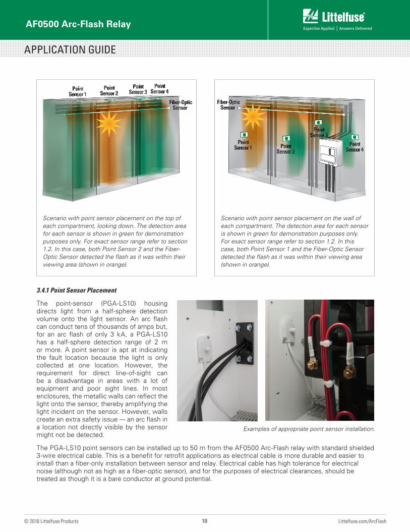
Scenario with point sensor placement on the wall of each compartment. The detection area for each sensor is shown in green for demonstration purposes only. For exact sensor range refer to section 1.2. In this case, both Point Sensor 1 and the Fiber-Optic Sensor detected the flash as it was within their viewing area (shown in orange).
Scenario with point sensor placement on the top of each compartment, looking down. The detection area for each sensor is shown in green for demonstration purposes only. For exact sensor range refer to section 1.2. In this case, both Point Sensor 2 and the Fiber-Optic Sensor detected the flash as it was within their viewing area (shown in orange).
3.4.1 Point Sensor Placement
The point-sensor (PGA-LS10) housing directs light from a half-sphere detection volume onto the light sensor. An arc flash can conduct tens of thousands of amps but, for an arc flash of only 3 kA, a PGA-LS10 has a half-sphere detection range of 2 m or more. A point sensor is apt at indicating the fault location because the light is only collected at one location. However, the requirement for direct line-of-sight can be a disadvantage in areas with a lot of equipment and poor sight lines. In most enclosures, the metallic walls can reflect the light onto the sensor, thereby amplifying the light incident on the sensor. However, walls create an extra safety issue — an arc flash in a location not directly visible by the sensor might not be detected.
The PGA-LS10 point sensors can be installed up to 50 m from the AF0500 Arc-Flash relay with standard shielded 3-wire electrical cable. This is a benefit for retrofit applications as electrical cable is more durable and easier to install than a fiber-only installation between sensor and relay. Electrical cable has high tolerance for electrical noise (although not as high as a fiber-optic sensor), and for the purposes of electrical clearances, should be treated as though it is a bare conductor at ground potential.
Examples of appropriate point sensor installation.
AF0500 Arc-Flash Relay
APPLICATION GUIDE
11 Littelfuse.com/ArcFlash© 2016 Littelfuse Products
Example of appropriate fiber optic sensor installation.
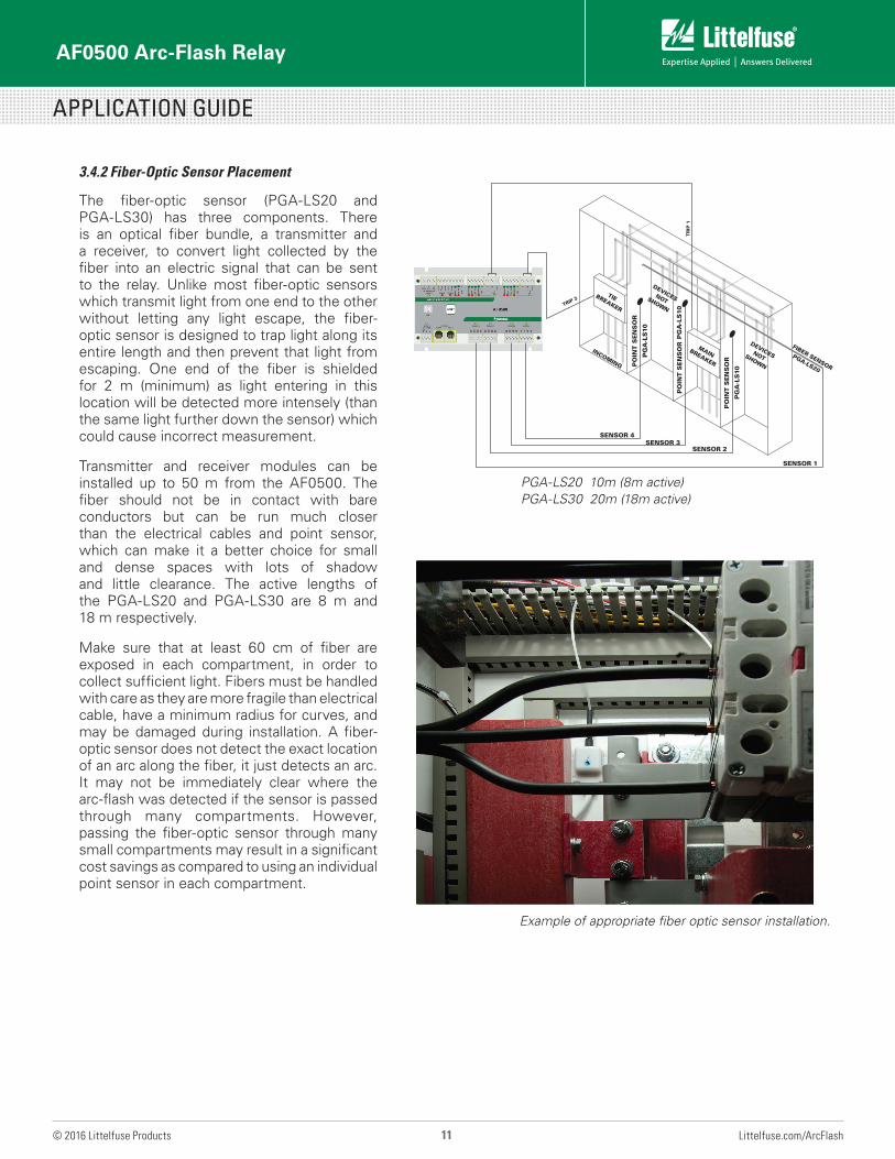
3.4.2 Fiber-Optic Sensor Placement
The fiber-optic sensor (PGA-LS20 and PGA-LS30) has three components. There is an optical fiber bundle, a transmitter and a receiver, to convert light collected by the fiber into an electric signal that can be sent to the relay. Unlike most fiber-optic sensors which transmit light from one end to the other without letting any light escape, the fiber-optic sensor is designed to trap light along its entire length and then prevent that light from escaping. One end of the fiber is shielded for 2 m (minimum) as light entering in this location will be detected more intensely (than the same light further down the sensor) which could cause incorrect measurement.
Transmitter and receiver modules can be installed up to 50 m from the AF0500. The fiber should not be in contact with bare conductors but can be run much closer than the electrical cables and point sensor, which can make it a better choice for small and dense spaces with lots of shadow and little clearance. The active lengths of the PGA-LS20 and PGA-LS30 are 8 m and 18 m respectively.
Make sure that at least 60 cm of fiber are exposed in each compartment, in order to collect sufficient light. Fibers must be handled with care as they are more fragile than electrical cable, have a minimum radius for curves, and may be damaged during installation. A fiber-optic sensor does not detect the exact location of an arc along the fiber, it just detects an arc. It may not be immediately clear where the arc-flash was detected if the sensor is passed through many compartments. However, passing the fiber-optic sensor through many small compartments may result in a significant cost savings as compared to using an individual point sensor in each compartment.
SENSOR 1
SENSOR 4
SENSOR 2SENSOR 3
FIBER SENSOR
PGA-LS20
TIEBREAKER
PO
INT
SE
NS
OR
PG
A-L
S10
PO
INT
SE
NS
OR
PG
A-L
S10
PO
INT
SE
NS
OR
PG
A-L
S10
DEVICES NOT SHOWN
DEVICES NOT SHOWN
INCOMING
MAINBREAKER
TRIP 2
TR
IP 1
PGA-LS20 10m (8m active)PGA-LS30 20m (18m active)
AF0500 Arc-Flash Relay
APPLICATION GUIDE
12 Littelfuse.com/ArcFlash© 2016 Littelfuse Products
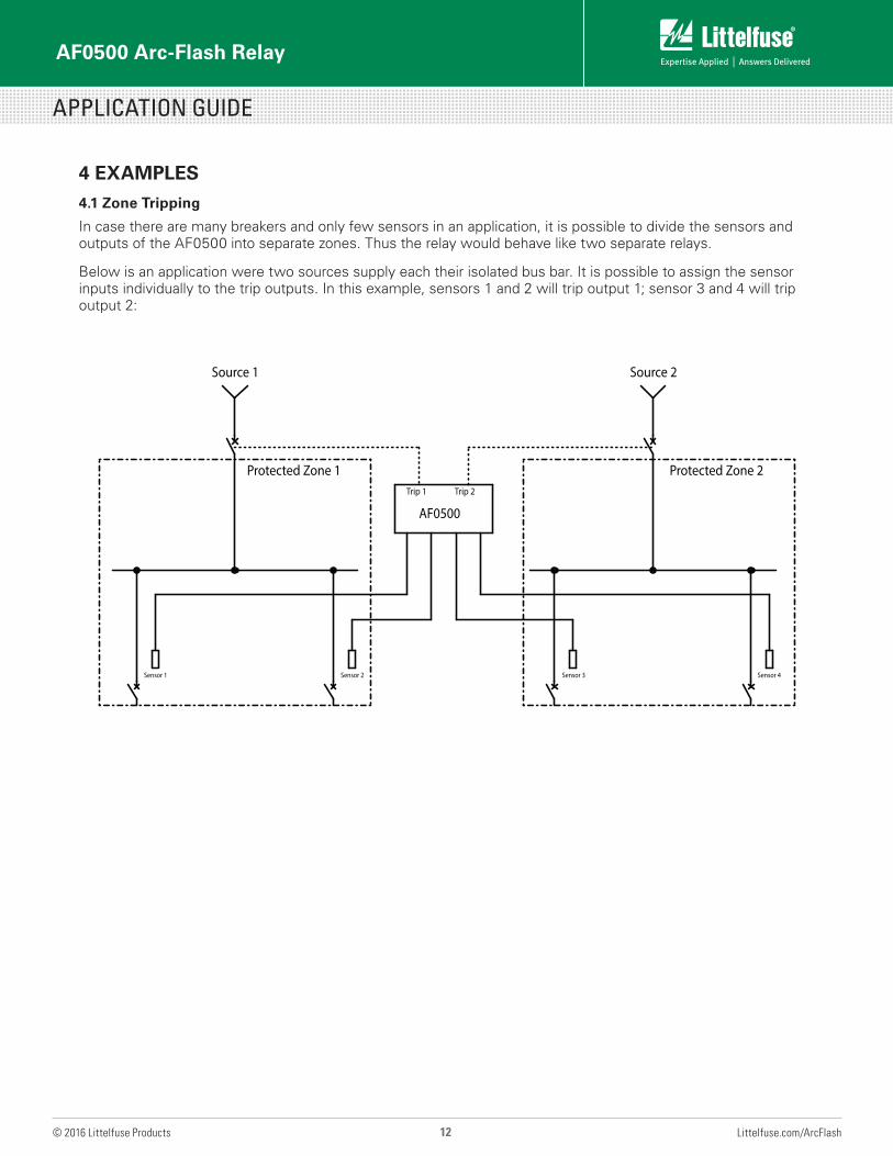
4 EXAMPLES
4.1 Zone Tripping
In case there are many breakers and only few sensors in an application, it is possible to divide the sensors and outputs of the AF0500 into separate zones. Thus the relay would behave like two separate relays.
Below is an application were two sources supply each their isolated bus bar. It is possible to assign the sensor inputs individually to the trip outputs. In this example, sensors 1 and 2 will trip output 1; sensor 3 and 4 will trip output 2:
AF0500
Trip 1 Trip 2
Sensor 1 Sensor 2 Sensor 3 Sensor 4
Protected Zone 1 Protected Zone 2
Source 1 Source 2
AF0500 Arc-Flash Relay
APPLICATION GUIDE
13 Littelfuse.com/ArcFlash© 2016 Littelfuse Products
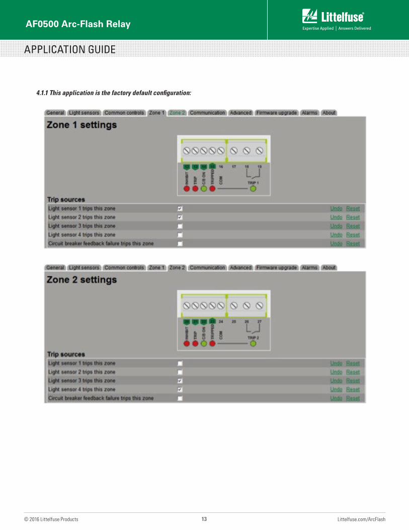
4.1.1 This application is the factory default configuration:
AF0500 Arc-Flash Relay
APPLICATION GUIDE
14 Littelfuse.com/ArcFlash© 2016 Littelfuse Products
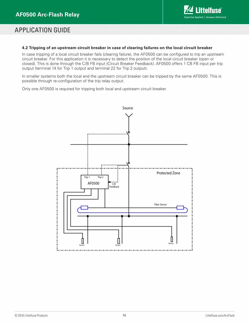
4.2 Tripping of an upstream circuit breaker in case of clearing failures on the local circuit breaker
In case tripping of a local circuit breaker fails (clearing failure), the AF0500 can be configured to trip an upstream circuit breaker. For this application it is necessary to detect the position of the local circuit breaker (open or closed). This is done through the C/B FB input (Circuit Breaker Feedback). AF0500 offers 1 CB FB input per trip output (terminal 14 for Trip 1 output and terminal 22 for Trip 2 output).
In smaller systems both the local and the upstream circuit breaker can be tripped by the same AF0500. This is possible through re-configuration of the trip relay output.
Only one AF0500 is required for tripping both local and upstream circuit breaker.
SensorSensor
Sensor
AF0500
Trip 1 Trip 2
Source
Fiber Sensor
Protected Zone
C/B Feedback
AF0500 Arc-Flash Relay
APPLICATION GUIDE
15 Littelfuse.com/ArcFlash© 2016 Littelfuse Products
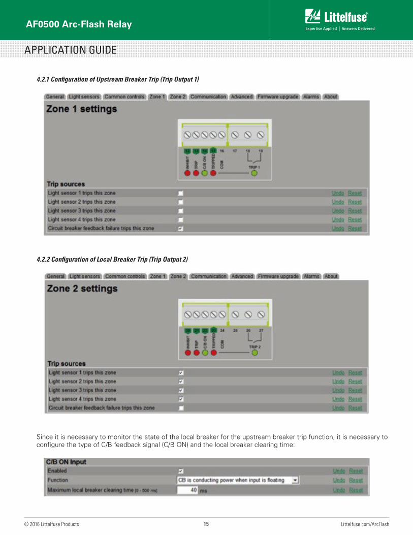
4.2.1 Configuration of Upstream Breaker Trip (Trip Output 1)
4.2.2 Configuration of Local Breaker Trip (Trip Output 2)
Since it is necessary to monitor the state of the local breaker for the upstream breaker trip function, it is necessary to configure the type of C/B feedback signal (C/B ON) and the local breaker clearing time:
AF0500 Arc-Flash Relay
APPLICATION GUIDE
16 Littelfuse.com/ArcFlash© 2016 Littelfuse Products
Options:
CB is conducting power when input is pulled low, means that the auxiliary contact of the C/B is open when the C/B is open and closed when the C/B is closed (a normally open contact).
CB is conducting power when input is floating, means that the auxiliary contact of the C/B is open when the C/B is closed (a normally closed contact). When configured like this, a cable break on the C/B feedback connection would cause the upstream breaker to trip in the event of an arc. Thus it gives additional safety.
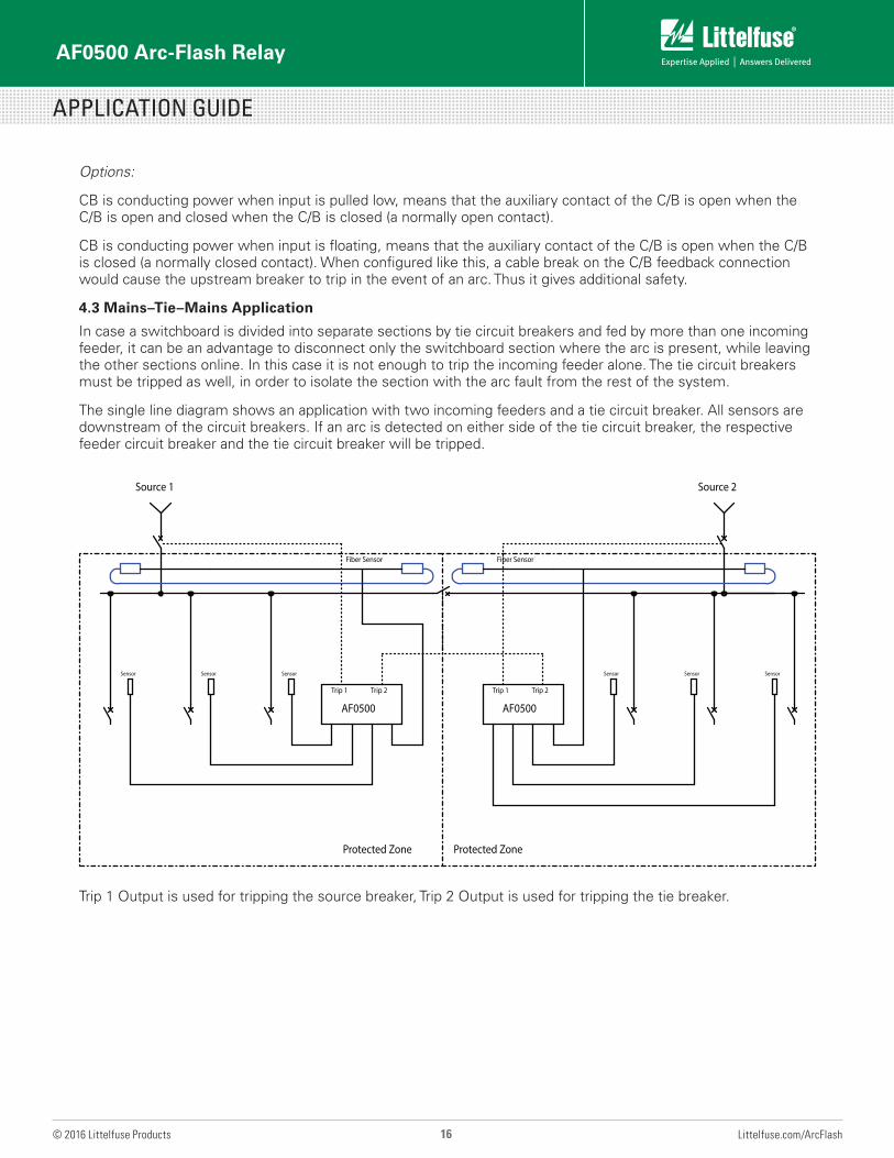
4.3 Mains–Tie–Mains Application
In case a switchboard is divided into separate sections by tie circuit breakers and fed by more than one incoming feeder, it can be an advantage to disconnect only the switchboard section where the arc is present, while leaving the other sections online. In this case it is not enough to trip the incoming feeder alone. The tie circuit breakers must be tripped as well, in order to isolate the section with the arc fault from the rest of the system.
The single line diagram shows an application with two incoming feeders and a tie circuit breaker. All sensors are downstream of the circuit breakers. If an arc is detected on either side of the tie circuit breaker, the respective feeder circuit breaker and the tie circuit breaker will be tripped.
Source 1 Source 2
Sensor Sensor Sensor
AF0500
Trip 1 Trip 2
AF0500
Trip 1 Trip 2
Fiber Sensor Fiber Sensor
Sensor Sensor Sensor
Protected Zone Protected Zone
Trip 1 Output is used for tripping the source breaker, Trip 2 Output is used for tripping the tie breaker.
AF0500 Arc-Flash Relay
APPLICATION GUIDE
17 Littelfuse.com/ArcFlash© 2016 Littelfuse Products
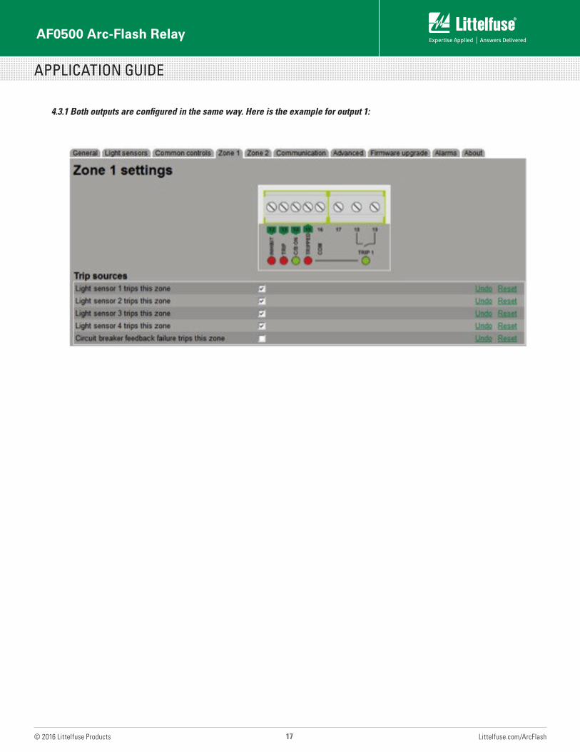
4.3.1 Both outputs are configured in the same way. Here is the example for output 1:
AF0500 Arc-Flash Relay
APPLICATION GUIDE
18 Littelfuse.com/ArcFlash© 2016 Littelfuse Products
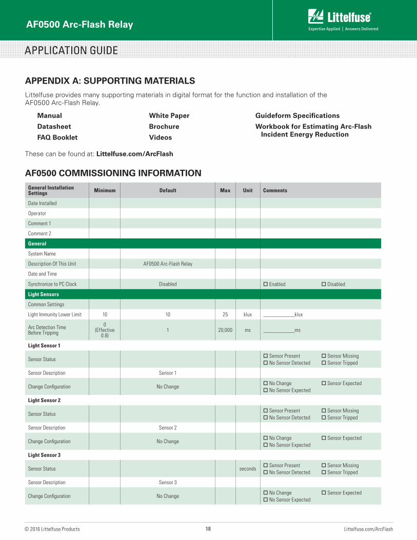
APPENDIX A: SUPPORTING MATERIALS
Littelfuse provides many supporting materials in digital format for the function and installation of the AF0500 Arc-Flash Relay.
These can be found at: Littelfuse.com/ArcFlash
AF0500 COMMISSIONING INFORMATION
Manual
Datasheet
FAQ Booklet
White Paper
Brochure
Videos
Guideform Specifications
Workbook for Estimating Arc-Flash Incident Energy Reduction
General Installation Settings Minimum Default Max Unit Comments
Date Installed
Operator
Comment 1
Comment 2
General
System Name
Description Of This Unit AF0500 Arc-Flash Relay
Date and Time
Synchronize to PC Clock Disabled o Enabled o Disabled
Light Sensors
Common Settings
Light Immunity Lower Limit 10 10 25 klux klux
Arc Detection Time Before Tripping
0 (Effective
0.8)1 20,000 ms ms
Light Sensor 1
Sensor Statuso Sensor Presento No Sensor Detected
o Sensor Missingo Sensor Tripped
Sensor Description Sensor 1
Change Configuration No Changeo No Changeo No Sensor Expected
o Sensor Expected
Light Sensor 2
Sensor Statuso Sensor Presento No Sensor Detected
o Sensor Missingo Sensor Tripped
Sensor Description Sensor 2
Change Configuration No Changeo No Changeo No Sensor Expected
o Sensor Expected
Light Sensor 3
Sensor Status secondso Sensor Presento No Sensor Detected
o Sensor Missingo Sensor Tripped
Sensor Description Sensor 3
Change Configuration No Changeo No Changeo No Sensor Expected
o Sensor Expected
AF0500 Arc-Flash Relay
APPLICATION GUIDE
19 Littelfuse.com/ArcFlash© 2016 Littelfuse Products
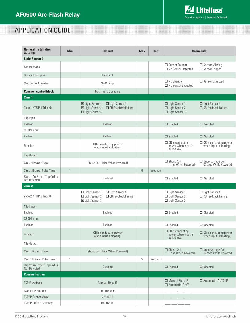
General Installation Settings Min Default Max Unit Comments
Light Sensor 4
Sensor Statuso Sensor Presento No Sensor Detected
o Sensor Missingo Sensor Tripped
Sensor Description Sensor 4
Change Configuration No Changeo No Changeo No Sensor Expected
o Sensor Expected
Common control block Nothing To Configure
Zone 1
Zone 1 / TRIP 1 Trips OnT Light Sensor 1T Light Sensor 2o Light Sensor 3
o Light Sensor 4o CB Feedback Failure
o Light Sensor 1o Light Sensor 2o Light Sensor 3
o Light Sensor 4o CB Feedback Failure
Trip Input
Enabled Enabled o Enabled o Disabled
CB ON Input
Enabled Enabled o Enabled o Disabled
Function CB is conducting power when input is floating.
o CB is conducting power when input is pulled low.
o CB is conducting power when input is floating.
Trip Output
Circuit Breaker Type Shunt Coil (Trips When Powered) o Shunt Coil (Trips When Powered)
o Undervoltage Coil (Closed While Powered)
Circuit Breaker Pulse Time 1 1 5 seconds
Report An Error If Trip Coil Is Not Detected Enabled o Enabled o Disabled
Zone 2
Zone 2 / TRIP 2 Trips Ono Light Sensor 1o Light Sensor 2T Light Sensor 3
T Light Sensor 4o CB Feedback Failure
o Light Sensor 1o Light Sensor 2o Light Sensor 3
o Light Sensor 4o CB Feedback Failure
Trip Input
Enabled Enabled o Enabled o Disabled
CB ON Input
Enabled Enabled o Enabled o Disabled
Function CB is conducting power when input is floating.
o CB is conducting power when input is pulled low.
o CB is conducting power when input is floating.
Trip Output
Circuit Breaker Type Shunt Coil (Trips When Powered) o Shunt Coil (Trips When Powered)
o Undervoltage Coil (Closed While Powered)
Circuit Breaker Pulse Time 1 1 5 seconds
Report An Error If Trip Coil Is Not Detected Enabled o Enabled o Disabled
Communication
TCP IP Address Manual Fixed IPo Manual Fixed IPo Automatic (DHCP)
o Automatic (AUTO IP)
Manual IP Address 192.168.0.99 . . .
TCP/IP Subnet Mask 255.0.0.0 . . .
TCP/IP Default Gateway 192.168.0.1 . . .

Additional technical information and application data for Littelfuse protection relays, generator and engine controls, fuses and other circuit protection and safety products can be found on Littelfuse.com. For questions, contact our Technical Support Group (800-832-3873). Specifications, descriptions and illustrative material in this literature are as accurate as known at the time of publication, but are subject to changes without notice. All data was compiled from public information available from manufacturers’ manuals and datasheets.
© 2016 Littelfuse, Inc. Form: PF718 Rev: 2-B-020416
For more information, visit
Littelfuse.com/ArcFlash