training agenda - littelfuse.com/media/electronics/trainings/littelfuse_mov_general... ·...
TRANSCRIPT

1 Confidential and Proprietary to Littelfuse, Inc. © 2007 Littelfuse, Inc. All rights reserved.
General Electrical MOV Training
Training Agenda
1. MOV Definition and Circuit Protection
2. MOV Characteristics and Device Physics
3. MOV General Electrical Power Application Example
4. MOV Product Selection
5. Littelfuse MOV Product Road Map
6. MOV Technology Challenges

2 Confidential and Proprietary to Littelfuse, Inc. © 2007 Littelfuse, Inc. All rights reserved.
General Electrical MOV Training
Section 1 MOV Definition and Circuit Protection MOV Definition
– A MOV is a voltage suppression device that filters and clamps the transient in the electrical circuit
Circuit Protection Concepts
– Threats
• Repetitive Transients
• Random Transients
• General Electrical Line Transients
– Effects of Voltage Transients
• Effects on Semiconductors
• Effects on Electro-mechanical Contacts
• Effects on Insulation
– Transient Testing and Standards
• Regulatory Requirements
• UL Regulation
– Transient Suppression Method
• Clamping
• Crowbar
• Filters
• Transient Suppression Compared
3 Confidential and Proprietary to Littelfuse, Inc. © 2007 Littelfuse, Inc. All rights reserved.
MOV Definition and General Electrical Circuit Protection
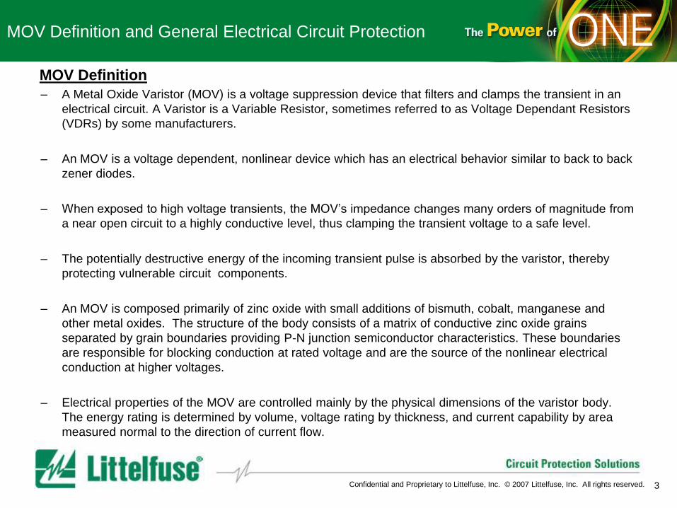
MOV Definition
– A Metal Oxide Varistor (MOV) is a voltage suppression device that filters and clamps the transient in an
electrical circuit. A Varistor is a Variable Resistor, sometimes referred to as Voltage Dependant Resistors
(VDRs) by some manufacturers.
– An MOV is a voltage dependent, nonlinear device which has an electrical behavior similar to back to back
zener diodes.
– When exposed to high voltage transients, the MOV’s impedance changes many orders of magnitude from
a near open circuit to a highly conductive level, thus clamping the transient voltage to a safe level.
– The potentially destructive energy of the incoming transient pulse is absorbed by the varistor, thereby
protecting vulnerable circuit components.
– An MOV is composed primarily of zinc oxide with small additions of bismuth, cobalt, manganese and
other metal oxides. The structure of the body consists of a matrix of conductive zinc oxide grains
separated by grain boundaries providing P-N junction semiconductor characteristics. These boundaries
are responsible for blocking conduction at rated voltage and are the source of the nonlinear electrical
conduction at higher voltages.
– Electrical properties of the MOV are controlled mainly by the physical dimensions of the varistor body.
The energy rating is determined by volume, voltage rating by thickness, and current capability by area
measured normal to the direction of current flow.

4 Confidential and Proprietary to Littelfuse, Inc. © 2007 Littelfuse, Inc. All rights reserved.
MOV Definition and General Electrical Circuit Protection
Circuit Protection Needs in General Electrical Systems
– A sudden change in the electrical conditions of any circuit will cause a transient voltage to be
generated from the energy stored in circuit inductance and capacitance. The rate of change in
current in an inductor will generate a switching-induced transient voltage.
– Energizing the transformer primary
• When a transformer is energized at the peak of the supply voltage, the coupling of this voltage
step function to the stray capacitance and inductance of the secondary winding can generate
an oscillatory transient voltage with a peak amplitude up to twice the normal peak secondary
voltage.
– De-Energizing the transformer primary
• The opening of the primary circuit of a transformer generates extreme voltage transients.
Transients in excess of ten times normal voltage have been observed across power
semiconductors when this type of switching occurs.
– Fault with inductive power source
• If a short develops on any power system, devices parallel to the load may be destroyed as the
fuse clears.
– Switch arcing
• When current in an inductive circuit is interrupted by a contactor, the inductance tries to
maintain its current by charging the stray capacitance.
5 Confidential and Proprietary to Littelfuse, Inc. © 2007 Littelfuse, Inc. All rights reserved.
MOV Definition and General Electrical Circuit Protection
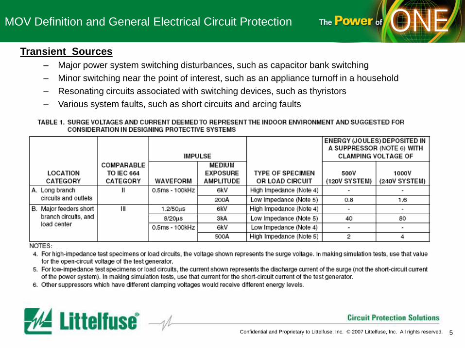
Transient Sources
– Major power system switching disturbances, such as capacitor bank switching
– Minor switching near the point of interest, such as an appliance turnoff in a household
– Resonating circuits associated with switching devices, such as thyristors
– Various system faults, such as short circuits and arcing faults

6 Confidential and Proprietary to Littelfuse, Inc. © 2007 Littelfuse, Inc. All rights reserved.
MOV Definition and General Electrical Circuit Protection
MOV as Transient Suppression Device
There are two major categories of transient suppressors:
a) Diverting transients away from sensitive loads and thus limit the residual voltage
– Voltage Clamping type
– Crowbar type
b) Attenuate transients and preventing them from propagating into the circuit to be protected
– Filters inserted in series within a circuit
– Attenuates high frequency and allows the signal or power flow to continue undisturbed
MOV as a voltage clamping device
– Circuit is essentially unaffected by the presence of
the device before and after the transient for any
steady-state voltage below the clamping level of the
MOV used.
– The voltage clamping action results from the
increased current drawn through the device as the
voltage across it rises. The clamping of the voltage
results from the increased voltage drop across the
source impedance.
The MOV depends on the source impedance
to effectively clamp.
VLINE
Transient on Line
Energy Dissipated
Clamp Voltage

7 Confidential and Proprietary to Littelfuse, Inc. © 2007 Littelfuse, Inc. All rights reserved.
General Electrical MOV Training
Section 2 MOV Characteristics and Device Physics
Measurement of Varistor Characteristics
– Electrical Characteristics
• Nominal varistor voltage VN
• Maximum Clamping Voltage VC
• DC Standby Current ID
– Maximum ratings
• Continuous / Rated RMS and DC Voltage
• Continuous Power Dissipation
– Thermal Characteristics
• De-rating
– Signal Integrity Characteristics
• Capacitance at 1MHz
Varistor Construction and how it affects the related Varistor characteristics
– Varistor Construction
– Varistor Energy Band
– Varistor Thermal Barrier
8 Confidential and Proprietary to Littelfuse, Inc. © 2007 Littelfuse, Inc. All rights reserved.
MOV Characteristics and Device Physics
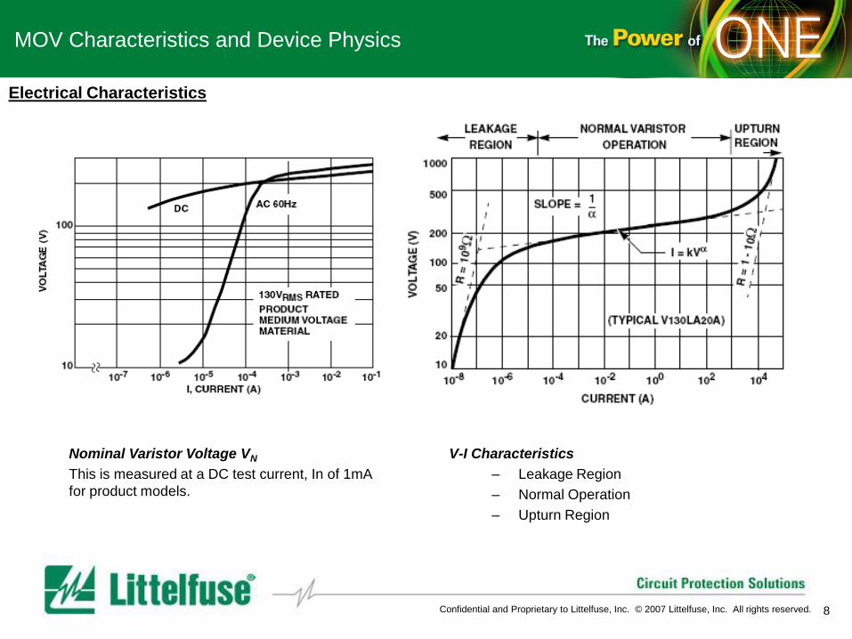
Electrical Characteristics
Nominal Varistor Voltage VN
This is measured at a DC test current, In of 1mA
for product models.
V-I Characteristics
– Leakage Region
– Normal Operation
– Upturn Region

9 Confidential and Proprietary to Littelfuse, Inc. © 2007 Littelfuse, Inc. All rights reserved.
MOV Characteristics and Device Physics
Electrical Characteristics
Temperature Dependence in the Leakage
Region
Continuous Power Dissipation
Since MOVs are used primarily for transient
suppression purpose, their power dissipation rating
has been defined and tested under transient
impulse conditions as outlined above.
The above table outlines a suggested program of
testing to verify MOV transient and pulse ratings
with a minimum of testing.

10 Confidential and Proprietary to Littelfuse, Inc. © 2007 Littelfuse, Inc. All rights reserved.
MOV Characteristics and Device Physics
Schematic depiction of the microstructure of a MOV
Grains of conducting ZnO averaged size “d” are
separated by intergranular boundaries.
Device Constructions
Optical Photomicrograph
Cross section of a polished and etched varistor
element

11 Confidential and Proprietary to Littelfuse, Inc. © 2007 Littelfuse, Inc. All rights reserved.
MOV Characteristics and Device Physics
Energy band diagram of a ZnO Grain-
boundary ZnO junction
Device Operation Theory
Thermal Barrier vs Applied Voltage Chart
This varistor theory draws its inspiration from
semiconductor transport theory.

12 Confidential and Proprietary to Littelfuse, Inc. © 2007 Littelfuse, Inc. All rights reserved.
General Electrical MOV Training
Section 3 MOV General Electrical Power Applications Examples
– Power Supply Protection
– SCR Motor Control
– Contact Arcing (due to inductive load)
– Noise Suppression
– Protection of Transistors (switching inductive loads)
– Motor Protection
13 Confidential and Proprietary to Littelfuse, Inc. © 2007 Littelfuse, Inc. All rights reserved.
MOV General Electrical Power Applications Examples
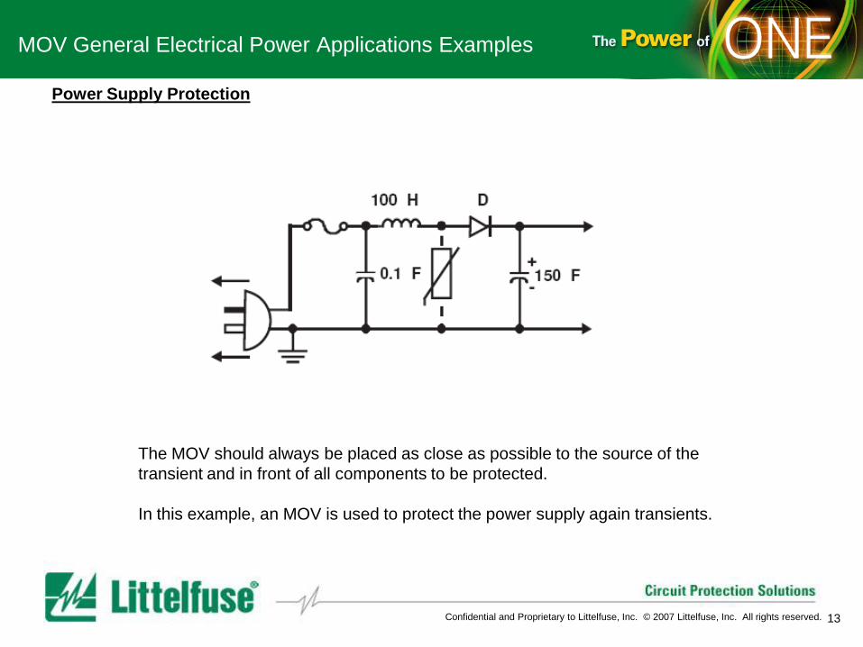
Power Supply Protection
The MOV should always be placed as close as possible to the source of the
transient and in front of all components to be protected.
In this example, an MOV is used to protect the power supply again transients.

14 Confidential and Proprietary to Littelfuse, Inc. © 2007 Littelfuse, Inc. All rights reserved.
MOV General Electrical Power Applications Examples
SCR Motor Control
In this circuitry, an MOV would be used to protect the rectifier and SCR against
transients when the power is switched off.

15 Confidential and Proprietary to Littelfuse, Inc. © 2007 Littelfuse, Inc. All rights reserved.
MOV General Electrical Power Applications Examples
Contact arcing due to inductive load
In this circuitry, an MOV would be used to protect the transient for relay and therefore
extend the service life of the relays.

16 Confidential and Proprietary to Littelfuse, Inc. © 2007 Littelfuse, Inc. All rights reserved.
MOV General Electrical Power Applications Examples
Noise Suppression
In this circuitry, an MOV would be used to reduce the noise generated from the
mechanical contacts switching on and off.

17 Confidential and Proprietary to Littelfuse, Inc. © 2007 Littelfuse, Inc. All rights reserved.
MOV General Electrical Power Applications Examples
Motor Protection
In this application, an MOV would be used to protect the transient for the
motor from its insulation breakdown.

18 Confidential and Proprietary to Littelfuse, Inc. © 2007 Littelfuse, Inc. All rights reserved.
MOV Applications Protection Examples
Global Lab Capabilities • Qualification of all LF products
• UL-Approved Customer Testing in ISO 17025 Lab (Des Plaines)
– High power (AC/DC up to 1KV/50KA) UL approvals available in DP
– Telcordia approvals in DP planned (2008)
• Verification of Telcordia, ITU, IEC, FCC, and other industry, regulatory, and safety standards
– Verification to various OC and OV standards
• Insure application meets standards before submitting for approval
• Customer Application testing
– Assistance with design-in and performance verification
• Help with selection of appropriate technology and rating
– Application troubleshooting
• Assistance insuring proper OV/OC and primary/secondary protection coordination
– Competitive evaluations
• Competitive or technology performance comparisons
– Reliability & Tin Whisker data/testing

19 Confidential and Proprietary to Littelfuse, Inc. © 2007 Littelfuse, Inc. All rights reserved.
General Electrical MOV Training
Section 4 MOV General Electrical Application Product Selection Varistor Product Selection
– Varistor Type/Series Selection
• Identify Varistor Regulatory Requirements
• Identify Varistor Dimensional Requirements
• Identify Varistor Surge Rating Requirement
• Identify Varistor Capacitance
– Varistor Rating Selection
• Identify Varistor Voltage Rating Requirement

20 Confidential and Proprietary to Littelfuse, Inc. © 2007 Littelfuse, Inc. All rights reserved.
MOV General Elec Application Product Selection
Varistor Product Selection Table
APPLICATION EXAMPLE TYPICAL SERIES SELECTED
TV/VCR/White Goods Office Equipment ZA, LA, UltraMOV, "C" III, CH, MA and ML Series
Motor Control ZA, LA, UltraMOV, "C" III, HA, HB, NA,
BA, BB, DA and DB Series
Transformer (Primary Protection) ZA, LA, UltraMOV, "C" III, BA, BB, DA,
DB, HA, HB, and NA Series
Instrumentation MA, ZA, ML, MLN and CH Series
Automotive (Primary / Secondary
Protection )
ZA, CH and AUML Series
Noise Suppression MA, ML, MLN, MLE, CH, ZA, LA, UltraMOV and "C" III
Series
Power Supply LA, UltraMOV, "C" III, ZA, HA, HB, NA, BA, BB, DA,
and DB Series
Transient Voltage Suppressor AC Power
Strip
TMOV, LA, UltraMOV, "C" III, Series
AC Distribution Panels LA, UltraMOV, "C" III, HA, HB, and NA Series
ESD Protection MLE, ML, MLN Series

21 Confidential and Proprietary to Littelfuse, Inc. © 2007 Littelfuse, Inc. All rights reserved.
MOV General Elec Applications Product Selection
MOV AC Selection Table
VOLTAGE
(V)
ENERGY
(J)
PACKAGING AND
OTHER
CONSIDERATIONS
PREFERRED
SERIES
130 - 1000 11 - 360
Through-Hole Mounting
Low/Medium AC Power
Lines
LA
"C" III
UltraMOV
130 - 275
11 - 23 Surface Mount
Leadless Chip
CH
130 - 750 270 - 1050 High - Energy Applications
Shock / Vibration
Environment
DA
HA, HB
NA
DB
130 - 880 450 - 3200 Rigid Terminals
Primary Power Line
Heavy Industrial
BA
1100 - 2800 3800 -
10000
Rigid Terminals
Heavy Industrial
BB
22 Confidential and Proprietary to Littelfuse, Inc. © 2007 Littelfuse, Inc. All rights reserved.
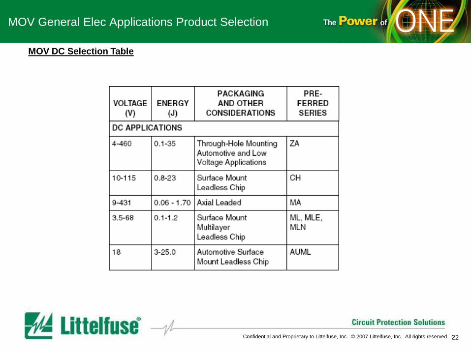
MOV General Elec Applications Product Selection
MOV DC Selection Table

23 Confidential and Proprietary to Littelfuse, Inc. © 2007 Littelfuse, Inc. All rights reserved.
General Elec MOV Training
Section 5 Littelfuse MOV Product Road Map
Leaded TMOV iTMOV
Pb-Free
SM 20
Industrial
IndTMOV
Integrated
Fusing
SMD
0805 Array
EMI/ESD Array
Pb-Free
Pb-Free
Pb-Free
2007 2006 2005
1449 3rd
0402
25mm TMOV
25mm

24 Confidential and Proprietary to Littelfuse, Inc. © 2007 Littelfuse, Inc. All rights reserved.
General Elec MOV Training
Section 6 General Elec MOV Technology Challenges
– Higher Surge Ratings in Smaller Packages
– Multiple Devices in One Package
– Varistor Technology Combined with Other Technologies in the Same Package
– Higher Operating Temperatures