application note 2017: water-source vrf application guide · ©2015 mitsubishi electric us, inc....
TRANSCRIPT

©2015 Mitsubishi Electric US, Inc.
Application Note 2017: Water-Source VRF Application Guide
Author Matt Rash, PE | Tiger Team Sr. Mechanical Engineer
Contributors Pamela Duffy, PE | Product Manager – Commercial Equipment
Reference Documents 2014 Engineering Manual – WY & WR2 – Section 2014 Engineering Manual – WY & WR2 – Design

July 2015 Application Note: 2017
P a g e | 2
©2015 Mitsubishi Electric US, Inc.
Table of Contents Introduction ................................................................................................................................................................ ....................................... 3
WHAT IS WATER SOURCE VRF? ............................................................................................................................................................... 3
SYSTEM APPLICATION & ADVANTAGES ............................................................................................................................................... 4
General Application Considerations ................................................................................................................................................... 4
Advantages of VRF versus Traditional WSHP Systems .............................................................................................................. 5
Advantages of Water-Source VRF versus Air-Source VRF ........................................................................................................ 5
Advantages to Geothermal Water-Source VRF versus Other Systems ................................................................................. 6
DESIGN CONSIDERATIONS ......................................................................................................................................................................... 7
System Operating Temperatures ......................................................................................................................................................... 7
Clearance Considerations & Maximizing Utility Space ............................................................................................................... 7
Heat Rejection Requirements ................................................................................................................................................................ 9
Closed Hydronic Loop Requirements ................................................................................................................................................ 9
Piping Connections at Water Source Unit ...................................................................................................................................... 10
General Piping Accessory Provisions at Water Source Unit ................................................................................................... 10
Condenser Water Pumping With Water-source VRF ................................................................................................................ 11
Option 1 – Full Condenser Water Flow Shutoff via Terminal Block 8 (TB8) .............................................................. 11
Option 2 – Partial Condenser Water Flow Shutoff via CN51, for twinned modules ................................................ 13
Option 2 – Partial Condenser Water Flow Shutoff via CN51, for twinned modules continued........................... 14
APPENDIX ......................................................................................................................................................................................................... 15
Schematic Piping Diagram Legend .................................................................................................................................................... 15
APPENDIX 1 – Traditional Boiler Tower Water Source VRF Diagram ............................................................................... 16
APPENDIX 2 – Geothermal Water Source VRF Plant with Optional Hybrid Schematic .............................................. 17
APPENDIX 3 – Partial Isolation Flow Control Schematic (Option #2) ............................................................................... 18

July 2015 Application Note: 2017
P a g e | 3
©2015 Mitsubishi Electric US, Inc.
Introduction This document is a general application guide for the Mitsubishi Electric CITY MULTI © water-source VRF equipment. This document is to serve as a supplement to the technical data already contained within the Mitsubishi Electric CITY MULTI © engineering manuals, submittal sheets, and other service, operation and installation manuals. This document will cover the general application of the following products: WR2-Series: PQRY-P72THMU (6 Ton) through PQRY-P240TSHMU (20 Ton) WY-Series: PQHY-P72THMU (6 Ton) through PQRY-P360TSHMU (30 Ton)
WHAT IS WATER SOURCE VRF? Water-source VRF is similar to air-source VRF on the refrigeration side. Multiple indoor units can be connected to a compressor module where each module houses a single inverter driven compressor. The primary difference is the fact that the compressor module absorbs and rejects heat from or to a water-source heat sink instead of an air-source heat sink. Two distinct types of water-source VRF systems are offered. The WR2-Series allows simultaneous heating and cooling between fan coil units attached to each individual system (Figure 1).
Figure 1. Water-Source VRF General Schematic. WR2-Series Shown.

July 2015 Application Note: 2017
P a g e | 4
©2015 Mitsubishi Electric US, Inc.
The WY-series requires that all the fan coil units attached to a system be in the same mode, either heating or cooling (Figure 2).
Figure 2. Water-Source VRF General Schematic. WY-Series Shown
Both the WR2 and WY-Series systems will provide heat recovery between modules connected to a common hydronic loop. However, only the WR2 can preferentially provide heat recovery on the refrigeration side first. The WR2 will then absorb or reject heat, from or to the building hydronic loop. The WY-Series is not capable of heat recovery on the refrigeration side.
SYSTEM APPLICATION & ADVANTAGES
General Application Considerations Similar to air-source VRF systems, consideration of load profile and zoning is important depending on the series of water-source VRF being applied. For the WY-Series, zones should be grouped with similar load profiles with similar exposures, occupancy schedules, and other internal load schedules. WY-Series VRF is also well suited to large open area applications. With the WR2-Series, providing a good mixture or balance of external and internal spaces with varying or opposite load profiles is advantageous to maximize heat recovery potential. Both water-source units are able to take advantage of building load diversity. The maximum allowable connected nominal capacity of fan coils is 130% for the WY-Series and up to 150% for the WR2-Series.
July 2015 Application Note: 2017
P a g e | 5
©2015 Mitsubishi Electric US, Inc.
In terms of heat recovery potential, the WR2-Series offers greater advantage compared to the WY-series. Both recover heat via the condenser water loop in the building, but the WR2 system recovers heat more efficiently.
Advantages of VRF versus Traditional WSHP Systems A simultaneous heating and cooling VRF system (WR2-Series) strives to meet the larger of the loads connected at any given hour. The lesser load is in the form of recovered energy via the refrigeration circuit. For example, if a majority of the building requires heating, recovered energy from the heating operation will be used for any spaces that demand cooling. Because of this, the compressor operating power in a VRF system will be reduced during heat recovery periods compared to that of an equivalently zoned traditional Water Source Heat Pump (WSHP) system. The traditional WSHP system will still require compressor operation in each zone, even during balanced (50/50 – heating/cooling) operation in the building. The serviceability of water-source VRF systems offers a major advantage over traditional WSHP systems as well. With traditional WSHP installations, the units are installed in the ceiling space. Since each unit contains a compressor (cyclically loaded compressors) the need for future maintenance and replacement of compressors is inevitable. Water-source VRF however will provide more centralized placement of compressors with reduced quantity. Instead of multiple compressors present in each zone unit, a single inverter driven compressor will exist in each water-source module. Each water-source module is capable of serving multiple zones and would be serviceable, for example, from a utility closet that houses the water-source VRF module at floor level for improved access and minimal disruption to occupied spaces.
Advantages of Water-Source VRF versus Air-Source VRF Probably the largest advantage water-source VRF offers in comparison to air-source VRF is heating de-rates for ambient temperature and defrosts in cold climates. Due to heating de-rates for air-source VRF, equipment must often be upsized to handle the peak heating demand or auxiliary heat installed throughout the building to cover colder periods. With water-source VRF equipment, there is an opportunity to centralize the heat source with a boiler without installing auxiliary heat at the zone level. Typically air-source VRF equipment is a good choice for energy savings opportunities because of its ability to source heat from ambient with a far greater extended heat pump operating range compared to traditional air-source heat pumps. However, water-source may offer an advantage in areas where the local utilities have higher electric rates, thus offering a greater value to heating with gas. Consider Figure 3 below. In this example, the electric blended rate is higher than the natural gas rate. For much of the heating season, defined as temperatures below 45°F WB, using natural gas with water-source VRF has a higher BTU/$ than air-source VRF. For this reason, water-source VRF, especially with improved efficiency in cooling, may be better suited in these situations.

July 2015 Application Note: 2017
P a g e | 6
©2015 Mitsubishi Electric US, Inc.
Figure 3. BTU per Dollar Comparison by Fuel Type
Advantages to Geothermal Water-Source VRF versus Other Systems The Mitsubishi Electric water-source equipment is also capable of operating in a closed loop ground source / geothermal heat sink application. Project site conditions and available funding along with local, state, and federal subsidy/rebate programs will always be key factors in assessing the viability of this application. In terms of year round energy savings potential, this application offers significant advantages. In many cases this application will yield improved cooling efficiency due to lower average loop water temperatures. This application also offers the ability to source heat from the geothermal heat sink at higher COP’s on average compared to air-source heat pump. In many cases the efficiency of these systems will exceed that of standard air-source VRF systems for the above reasons. In addition, ground source VRF will often exceed the efficiency of traditional geothermal WSHP systems due to the aforementioned ability to recover energy more efficiently on the refrigeration side first compared to multiple distributed traditional geothermal WSHPs. Again, providing a well field, as well as having land available for such installations, may be cost-prohibitive in many cases; careful analysis is always recommended. Sample system design schematics at the end of this application guide illustrate the major system components that may be required with traditional boiler tower water-source VRF and geothermal water-source VRF with optional hybrid applications.

July 2015 Application Note: 2017
P a g e | 7
©2015 Mitsubishi Electric US, Inc.
DESIGN CONSIDERATIONS
System Operating Temperatures Water-source VRF equipment is capable of operating in a wide range of water temperatures. Capacity is affected by the inlet water temperature. Table 1 summarizes the capacity reduction for inlet water temperature alone. This does not take into account other corrections for piping. Diamond System Builder should always be used to accurately account for all de-rates.
Table 1. Correction Factors for Water-Source VRF Based on Inlet Water Temperature
Cooling Correction Factors Inlet Water Temperature 23°F 50°F 85°F 113°F
Standard Correction Factor - 1.00 1.00 0.86 Low Temp. Correction Factor 1.00 1.00 1.00 0.86
Heating Correction Factors Inlet Water Temperature 23°F 50°F 85°F 113°F
Standard Correction Factor - 0.84 1.00 1.00 Low Temp. Correction Factor 0.65 .93 1.00 1.00
The standard operating low limit entering water temperature is 50 °F. This can be extended down to 23° F by adding glycol to the heat exchange loop and turning dip switch 3-9 to the ON position.
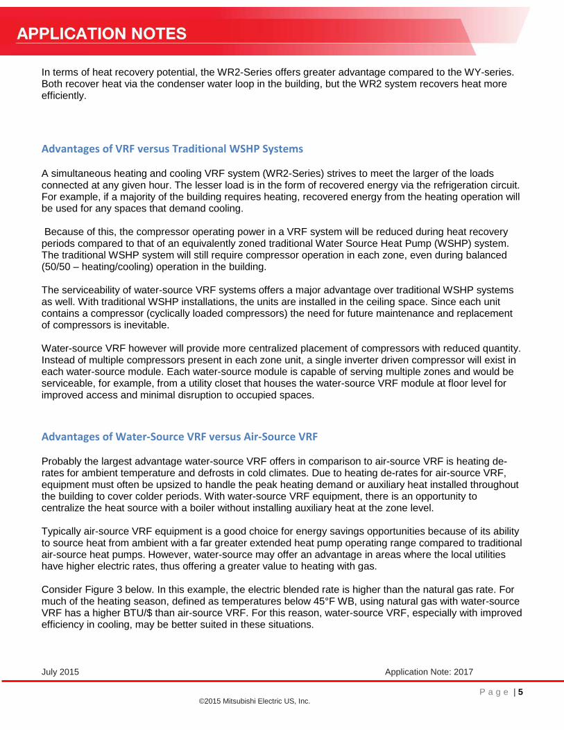
Clearance Considerations & Maximizing Utility Space Consideration of clearance requirements is important for proper space planning for the water-source modules. Unlike traditional water-source heat pumps which are ceiling mounted, VRF water-source modules can be installed at floor level for ease of access. One advantage the CITY MULTI © water-source VRF modules have is their ability to be installed in relatively small utility closets with little-to-no access on either side of the module. Service clearance can be achieved by simply opening the utility closet door where the unit is housed to reveal the front of the unit. The service clearance drawing from the Engineering Manual (Figure 4) reflects these requirements.
July 2015 Application Note: 2017
P a g e | 8
©2015 Mitsubishi Electric US, Inc.
Figure 4. Service clearance drawing from the Engineering Manual
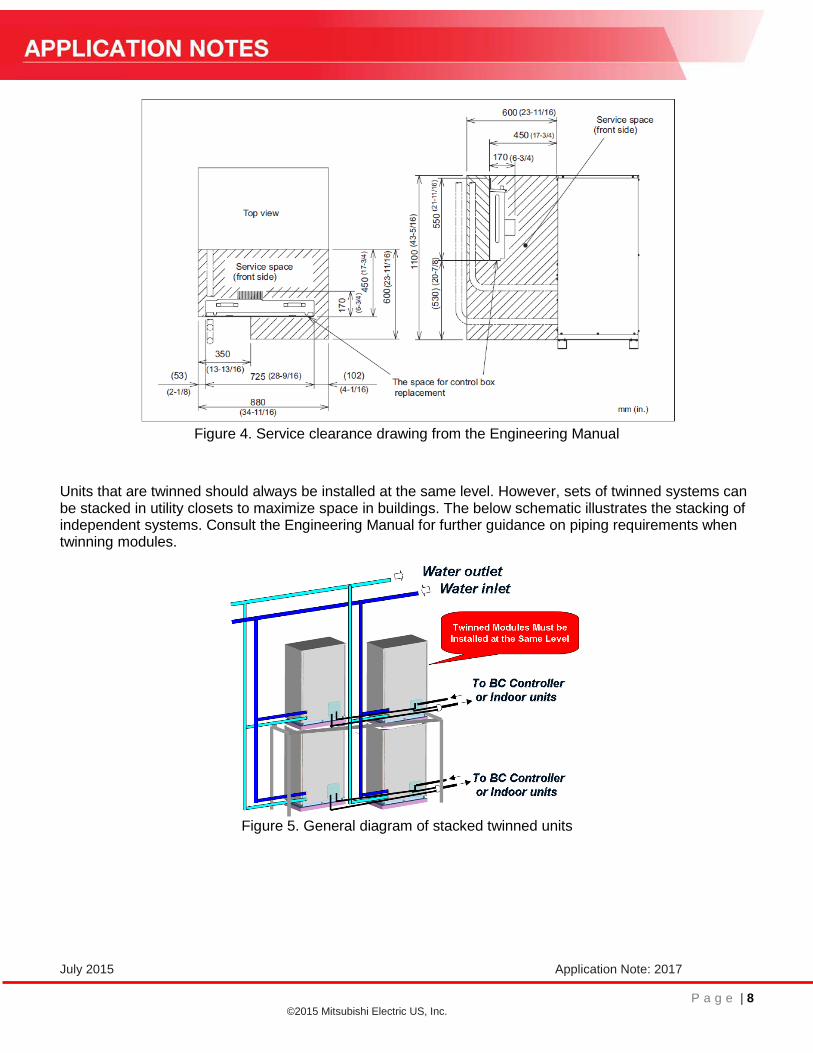
Units that are twinned should always be installed at the same level. However, sets of twinned systems can be stacked in utility closets to maximize space in buildings. The below schematic illustrates the stacking of independent systems. Consult the Engineering Manual for further guidance on piping requirements when twinning modules.
Figure 5. General diagram of stacked twinned units

July 2015 Application Note: 2017
P a g e | 9
©2015 Mitsubishi Electric US, Inc.
Heat Rejection Requirements When applying water-source VRF with a traditional boiler and tower, the capacity of the heat rejection device (e.g., evaporative tower, dry cooler, closed circuit cooling tower), becomes critical. At a minimum this device should be sized to dissipate the entire building cooling load, plus the VRF heat pump module compressor energy input, plus any pumping energy imparted on the circulating water loop. Equation 1 illustrates the required parameters to properly size the primary heat rejection device.
Equation 1. Cooling Tower Capacity Formula
𝐶𝑜𝑜𝑙𝑖𝑛𝑔 𝑇𝑜𝑤𝑒𝑟 𝐶𝑎𝑝𝑎𝑐𝑖𝑡𝑦 = 𝑄𝑐 + 3,412 × (∑𝑄𝑤 + 𝑃𝑤)
15,500 [𝑅𝑒𝑓𝑟𝑖𝑔𝑒𝑟𝑎𝑡𝑖𝑜𝑛 𝑇𝑜𝑛]
Qc: Actual Peak Cooling Load [BTU/h] Qw: Total input of water-source units at simultaneous peak operation [kW] Pw: Power of circulation pumps [kW]
If using a dry cooler, ensure:
1- The approach temperature used for sizing and selecting the dry cooler is based on the design ambient dry bulb condition for the climate you are designing for and,
2- The upper thresholds for the water-source VRF module inlet water temperature are not exceeded (Table 1). One way to check this is by using the ASHRAE “Extreme Annual DB” Mean-Max condition.
Table 2. Sample weather data from ASHRAE Fundamentals (Cincinnati, OH shown)
Closed Hydronic Loop Requirements All CITY MULTI © water-source VRF units are designed for closed loop heat exchange applications. Connections to any other open loop systems should be handled via a secondary heat exchanger. The closed loop system serving water-source VRF units should be chemically treated with corrosion and/or rust inhibitors, have balanced PH, and include air separation and water expansion devices. These measures are to ensure the integrity and performance of the refrigerant to water heat exchangers. Reference the sample schematic drawings at end of this guide for illustration of major hydronic components required. For geothermal applications with freezing winter loop temperatures expected, glycol must be provided in the heat exchange loop to provide freeze protection to at least 5° F. Since these units are intended for closed loop applications, circulation pumps must be used to circulate the heat exchange fluid through the unit. Pressure drop, flow ranges, and other piping losses must be considered to properly size the pump.

July 2015 Application Note: 2017
P a g e | 10
©2015 Mitsubishi Electric US, Inc.
Below is a sample pressure drop chart – consult the Mitsubishi Electric Engineering Manual for additional charts pertaining to pressure drop and other de-rates.
Figure 6 Water-Pressure Drop Chart (PQRY-P72 Shown)
Piping Connections at Water Source Unit Piping connections at water source modules follow British pipe thread standards, NOT NPT thread standard. If provisions cannot be made in field to connect piping with British pipe thread, optional British to NPT adaptors are available from Mitsubishi as an optional accessory. Failure to use the correct mating threads may result in leakage over time or with systems with high fill and/or operating pressures.
General Piping Accessory Provisions at Water Source Unit The units are equipped with brazed plate heat exchangers. These heat exchangers have multiple plates with small passages and as such are prone to partial clogging of debris/contaminants in system during initial flushing and debris arising over long term deterioration of piping systems in buildings. As such, a greater than 50 mesh strainer is required immediately at inlet connections of the water source modules. Failure to follow this may result in reduced flow, heat transfer, higher operating head pressure on refrigerant circuit, and resulting compressor power / energy use penalties. The below diagram illustrates some of the basic provisions that should be provided at each water source module:

July 2015 Application Note: 2017
P a g e | 11
©2015 Mitsubishi Electric US, Inc.
Figure 7 Minimum Piping Provisions at Each Water Source Module
Condenser Water Pumping With Water-source VRF In general, the Mitsubishi Electric water-source VRF modules are intended for continuous flow. The Engineering Manual provides a recommended flow range for condenser water through the modules. The units do not contain integral control devices to vary water flow rate through the unit. However, there are two options available to reduce water flow to the water-source VRF modules when the compressor has stopped operating.
Option 1 – Full Condenser Water Flow Shutoff via Terminal Block 8 (TB8)
Water-source modules contain a terminal block with dry contacts for proof of flow status via a field provided flow switch, as well as a dry contact to energize the control circuit for an auxiliary dedicated pump or motorized isolation valve.
Variable flow pumping can be achieved to some extent, predominantly during night set back periods, as single module systems become inactive or all modules in twinned set become inactive by installing motorized two position valves on each of the water source modules tied to the appropriate terminal block.

July 2015 Application Note: 2017
P a g e | 12
©2015 Mitsubishi Electric US, Inc.
Figure 8 Diagram showing Full Condenser Water Flow Shutoff
Systems comprised of twinned modules will not de-energize the field provided two position valves on any of the modules until all the modules become thermally inactive in the twinned set. Figure 8 depicts the interface of terminal block (TB8) on the water-source modules to this auxiliary pump / motorized isolation valve. Examples of how to apply this isolation can be found in the Appendix (see Appendix 1-2).
Figure 9 WR2 / WY Water-Source Unit Start Sequence
Note: SW2-7 must be set to “ON” to enable demand signal contact closure of TB8 terminal 1-2 for pump/valve interlock. SW2-8 should remain off – preliminary error code will be present initially but will clear when proof of flow via terminal 3-4 contact closure is made within 10 minutes.

July 2015 Application Note: 2017
P a g e | 13
©2015 Mitsubishi Electric US, Inc.
Option 2 – Partial Condenser Water Flow Shutoff via CN51, for twinned modules
Designs with two or three water-source VRF modules twinned together may experience part-load conditions such that one of the modules is operating, while any remaining modules are not. With this method, water flow can be reduced to a minimum flow rate in modules that are not operating. In twinned modules, water flow must be continuous if any of the modules is operating in order to maintain the integrity of the equipment. If the condenser water flow is less than 7 GPM, the heat exchanger may be damaged.
Figure 10 Partial condenser water flow shutoff with two twinned modules
Figure 11 Partial water flow isolation with three twinned modules

July 2015 Application Note: 2017
P a g e | 14
©2015 Mitsubishi Electric US, Inc.
Option 2 – Partial Condenser Water Flow Shutoff via CN51, for twinned modules continued.
In this application, it is recommended to use two auto flow limiting balancing valves. The first should be set to the minimum flow of 7 GPM (10 GPM is recommended), while the second valve is set to the remaining flow for the unit. Total flow for water-source units should be no less than 2 GPM per nominal ton. Schematics are provided in the Appendix (see Appendix 3). Selection of the flow switch in this Option is more critical. Appendix 3 indicates a recommended inline flow switch type. The switch should be selected for a 5 GPM break. As mentioned it is recommended to have the minimum flow bypass auto flow valve set for 10 gpm to allow a 5 gpm buffer between flow switch break to avoid nuisance flow alarms.

July 2015 Application Note: 2017
P a g e | 15
©2015 Mitsubishi Electric US, Inc.
APPENDIX
Schematic Piping Diagram Legend

July 2015 Application Note: 2017
P a g e | 16
©2015 Mitsubishi Electric US, Inc.
APPENDIX 1 – Traditional Boiler Tower Water Source VRF Diagram

July 2015 Application Note: 2017
P a g e | 17
©2015 Mitsubishi Electric US, Inc.
APPENDIX 2 – Geothermal Water Source VRF Plant with Optional Hybrid Schematic

July 2015 Application Note: 2017
P a g e | 18
©2015 Mitsubishi Electric US, Inc.
APPENDIX 3 – Partial Isolation Flow Control Schematic (Option #2)