application note #42 - conducted transients in road ... transients in road vehicles’ supply ......
TRANSCRIPT

1 of 17 112009
Application Note #42 Conducted Transients in Road Vehicles’ Supply Lines
Summary Over the last thirty years, the number of electrical/electronic modules used in road vehicles has increased dramatically. The modules are used in many diverse functions, including engine and transmission control, comfort and entertainment functions (radio, air conditioner and heater) and critical safety features (anti-lock brakes and air bag systems). All of the electrical and electronic systems must operate without interfering with each other and without reaction to outside interference signals. The road vehicle is subjected to radiate RF signals as well as onboard radiating signals of its own. In addition, the vehicles electrical system generates transients that are conducted via the power lines to the electrical/electronic modules connected to it. This note explains the transients that are conducted via the vehicle power system and the means by which the electrical/electronic modules are tested for immunity to the conducted transients. Introduction The ability of the road vehicles electrical/electronic system to operate in the vehicular electromagnetic environment is called Electromagnetic Compatibility (EMC). The U.S. government does not regulate the EMC of road vehicles in the sense that it regulates EMC of other equipment such as telephones and medical devices. The major controlling documents for EMC in road vehicles are created by the vehicle manufacturers themselves. In the U.S., these are mainly the big three auto manufacturers, DaimlerChrysler, Ford and General Motors. In addition, specifications outlining EMC performance for road vehicles are written by the Society of Automotive Engineers (SAE) and the International Organization for Standardization (ISO). Standards Used in Road Vehicle Transients on Supply Line Testing Automotive engineers want to insure that any electronic system used in the vehicle is able to function in its automotive environment. One way to do this is to test the module to a pertinent standard during its development and procurement. If all electronic modules pass the transient testing, then all modules should work in the actual automobile environment if the standard and transient generator used for the testing accurately resembles the vehicle electrical system in operation. Therefore, the transients and the transient generators used to qualify the electronic modules are characterized in the standards used by the manufacturers. A final functional test in the vehicle is performed to assure compatibility of all modules in conjunction with each other. As noted above, this application note applies to transients conducted along the vehicle DC supply lines. The transients discussed pertain to 12 V and 24 V systems, although much discussion has been going on about 42 V systems, an universal agreement by automotive engineers has not been reached on the definition of 42 V system transients. In the past few years, most of the major automotive manufacturers have migrated their transient definitions to match some or all of ISO 7637-2, which is the International Standard most recently published in the Second Edition in June 2004 by ISO.
2 of 17 112009
Below are some of the common specifications encountered by module designers and test engineers: Specification: Applicable to: ISO 7637-2 International standard for Supply Line Transients SAE J1113-11 USA Standard by the Society of Auto Engineers SAE J1455 USA Standard by the Society of Auto Engineers DC 10614/10615 DaimlerChrysler Standard ES-XW7T-1A278-AC Ford Standard GMW 3097 General Motors Standard GMW 3172 General Motors Standard JASO D001-94 Japanese Automotive Standard
Table 1: Vehicle Transient Standards.
Road Vehicle Transients Observed As noted above, the International Standard, ISO 7637-2 is being used by many in the automotive industry as the basis for transient specifications; we will review the characteristics of ISO 7637-2 pulses. The International Organization for Standardization labels the transient characteristics as pulses 1 through 5. The transients generated in the vehicle are created when systems are switched by relays or when solenoids are activated and deactivated or the connected electronic modules perform some intended operation. The switching operation causes changes of current flow along the vehicle wiring system. This creates transients on the power system because of the inherent parasitic effects of the distributed vehicle wiring. In other words, the vehicle wiring is inductive and capacitive in nature which then generates transients in the vehicular system. It is these transients that can cause unintended functions in electronic modules connected to the system supply if the modules themselves are not impervious to the applied transients. At some point in the past, the generated transients where observed in the vehicle after peculiar and unintended electrical functions occurred. As a result, specifications were developed by the manufacturers and other international organizations to require transient testing of electronic modules. Shown below in Figures 1 through 11 are the depictions of the transients commonly encountered in the Road Vehicle system. Pulse 1
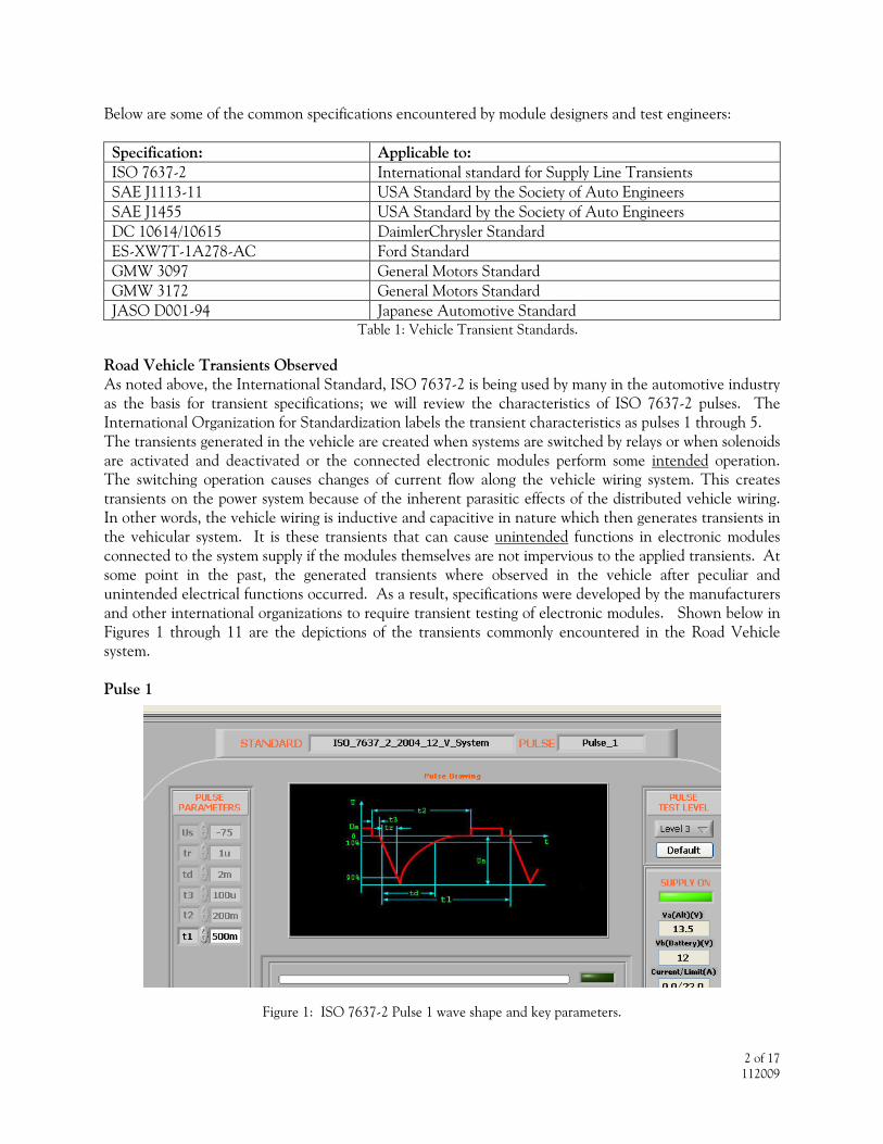
Figure 1: ISO 7637-2 Pulse 1 wave shape and key parameters.

3 of 17 112009
Figure 1 above illustrates the ISO 7637-2 Pulse 1. Pulse 1 simulates a negative polarity transient caused by the disconnection of the DC supply through an inductive load. This pulse applies to a device under test (frequently called a DUT) as used in the vehicle and connected directly in parallel to an inductive load. It is important to note that the vehicle DC power is first removed during the period t3 and the negative pulse is then discharged into the DUT. If the DC power were not removed, the negative Pulse 1 would be absorbed by system battery or battery simulator and not by the DUT, rendering the test pointless. Rise and fall times are specifically designated from 10% to 90% of maximum amplitude for all pulses. Pulse duration (td) is also specified for each pulse. Long duration pulses can cause more stress on the DUT as can faster rise times. Peak voltage, Us, varies according to the classification of the DUT. DUT's with more critical functions are subjected to larger amplitude voltages. The repetition rate (t1) and number of pulses applied to the DUT is usually controlled by the procurement agency and it varies dependent upon the intended system function of the DUT.
Parameter 12 V System 24 V System
Us -75V to -100V -450V to -600V Ri 10 Ω 50 Ω td 2 ms 1 ms tr 1 +0/-0.5µs 3 +0/-1.5µs t1 0.5 to 5 s 0.5 to 5 s t2 200 ms 200 ms t3 ≤ 100 µs ≤ 100 µs
Table 2: Pulse 1 Characteristics Notice in Table 2 that the source impedance (Ri) is specified. This will be important during bench testing of the DUT because it will influence the amount of energy delivered to the DUT. All the vehicle transient testing specifications describe the transient generator as an ideal pulsed transient generator with a series source resistor (Ri) that is purely resistive in nature. Pulse 2a
Figure 2: Pulse 2a wave shape and key parameters.

4 of 17 112009
ISO 7637-2 Pulse 2a above simulates transients caused by sudden interruptions of current in an inductive component connected in series with the DUT. The positive Pulse 2a is superimposed on the vehicle DC supply voltage. This pulse usually occurs in the vehicle when the ignition is switched on. Pulse 2a replaced Pulse 2 in the newest edition of ISO 7637. Pulse 2 was applied to the DUT with the DC power to the DUT removed. This was the time t2 referenced in Table 3 below. This time was 200ms, the time the power was removed from the DUT. Essentially, the old Pulse 2 test was merely a life test for the DUT. With the change of specification to Pulse 2a, this test became a functional test and it is likely to uncover more failures in the DUT. Also, the source resistance was reduced from 10 ohms to 2 ohms and the amplitude of Pulse 2a has been reduced from a maximum of 100V to 50V.
Parameter 12 V System 24 V System Us 37 to 50V 37 to 50V Ri 2 Ω 2 Ω td 50 µs 50 µs tr 10 +0/-0.5µs 10 +0/-0.5µs t1 0.2 S to 5S 0.2 S to 5S t2 Not Applicable Not Applicable
Table 3: Pulse 2a Characteristics Pulse 2b Pulse 2b is newly incorporated in the latest versions of ISO 7637, but automotive engineers have long known of its existence in the vehicle. This is frequently called the "PM motor rundown pulse" or the "motor shutdown pulse". This name refers to a permanent magnet motor such as the cooling or heating system blower motor, acting as a generator once the power to the motor has been removed. It was first noticed in automotive radios as a "burring" noise through the radio speaker when the ignition key is first turned off with the blower fan operating. It is a result of direct coupling of the radio speaker from the audio output transistors of the radio instead of using a coupling transformer. This type of audio output design was first utilized in the early 1970's. The blower motor supplies DC power to the audio system even though the DC supply has been removed. As a result, the auto engineers required testing of the radio and suppression of the phenomena. Subsequent specifications added testing of the motor shutdown pulse for all electronic modules and as a result it has become a requirement in international test specifications as well. The pulse waveshape is shown below in Figure 3. In figure 3, the time td is the amount of time voltage is being supplied by the PM motor after the DC power to the vehicle modules has been removed. The DC power is off for 1 to 1.5 ms and then the PM motor voltage is applied for a period of 0.2 to 2.0 seconds. All electronic modules used in the vehicle must be impervious to this spuriously generated voltage.

5 of 17 112009
Figure 3: Pulse 2b wave shape
Parameter 12 V System 24 V System Us 10 V 20 V Ri 0 to 0.05 Ω 0 to 0.05 Ω td 0.2 to 2.0 S 0.2 to 2.0 S t12 1.0 +/-0.5 ms 1.0 +/-0.5 ms tr 1.0 +/-0.5 ms 1.0 +/-0.5 ms t6 1.0 +/-0.5 ms 1.0 +/-0.5 ms
Table 4: Pulse 2b characteristics
Pulse 3a
Figure 4: Pulse 3a wave shape and key parameters

6 of 17 112009
Parameter 12 V System 24 V System
Us -112V to -150V -150V to -200V R 50 Ω 50 Ω td 0.1 +0.1/-0µs 0.1 +0.1/-0µs tr 5 +/-1.5ns 5 +/-1.5ns t1 100 µs 100 µs t4 10 ms 10 ms t5 90 ms 90 ms
Table 5: Pulse 3a characteristics Pulse 3b
Figure 5: Pulse 3b wave shape and key parameters
Parameter 12 V System 24 V System Us +75 to +100V +150 to +200V R 50 Ω 50 Ω td 0.1 +0.1/-0 µs 0.1 +0.1/-0 µs tr 5 +/-1.5ns 5 +/-1.5ns t1 100 µs 100 µs t4 10 ms 10 ms t5 90 ms 90 ms
Table 6: Pulse 3b characteristics Pulse 3a and 3b are negative and positive pulses that are identical in characteristics except for their polarity. They are similar to pulses identified in industrial and commercial EMC testing specifications as high frequency switching transients that occur on AC power mains and are called Electrical Fast Transients (EFT). In the vehicle their origins are similar in that these fast transients occur as arcing across contact points in mechanical switches and relays. Distributed capacitance and inductance in the wiring harness influence these transients, since the transients have rise and fall times (<5 ns) in the RF frequency range (>200 MHz). As a result, these transients are coupled by conduction and via radiation within the DUT. This can cause timing errors, memory losses and other functional errors within the
7 of 17 112009
DUT. DUT malfunctions caused by Pulse 3a and 3b are usually associated with wire placement problems, system grounding problems and pc board layout problems. Pulse 4
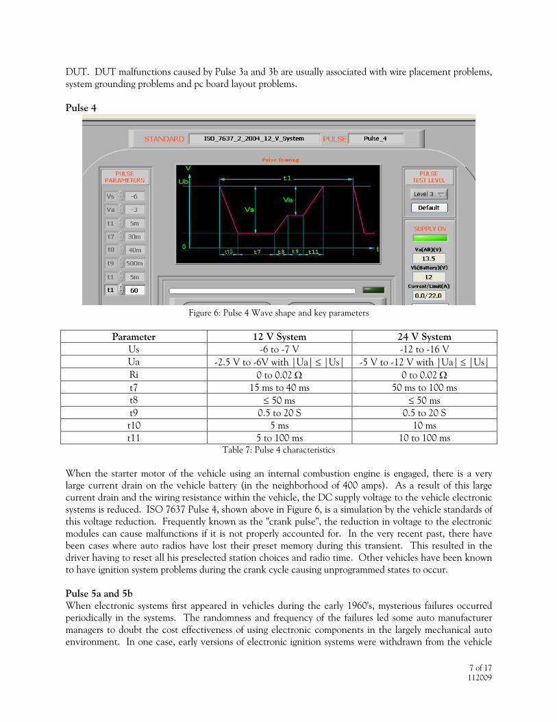
Figure 6: Pulse 4 Wave shape and key parameters
Parameter 12 V System 24 V System Us -6 to -7 V -12 to -16 V Ua -2.5 V to -6V with |Ua| ≤ |Us| -5 V to -12 V with |Ua| ≤ |Us| Ri 0 to 0.02 Ω 0 to 0.02 Ω t7 15 ms to 40 ms 50 ms to 100 ms t8 ≤ 50 ms ≤ 50 ms t9 0.5 to 20 S 0.5 to 20 S t10 5 ms 10 ms t11 5 to 100 ms 10 to 100 ms
Table 7: Pulse 4 characteristics When the starter motor of the vehicle using an internal combustion engine is engaged, there is a very large current drain on the vehicle battery (in the neighborhood of 400 amps). As a result of this large current drain and the wiring resistance within the vehicle, the DC supply voltage to the vehicle electronic systems is reduced. ISO 7637 Pulse 4, shown above in Figure 6, is a simulation by the vehicle standards of this voltage reduction. Frequently known as the "crank pulse", the reduction in voltage to the electronic modules can cause malfunctions if it is not properly accounted for. In the very recent past, there have been cases where auto radios have lost their preset memory during this transient. This resulted in the driver having to reset all his preselected station choices and radio time. Other vehicles have been known to have ignition system problems during the crank cycle causing unprogrammed states to occur. Pulse 5a and 5b When electronic systems first appeared in vehicles during the early 1960's, mysterious failures occurred periodically in the systems. The randomness and frequency of the failures led some auto manufacturer managers to doubt the cost effectiveness of using electronic components in the largely mechanical auto environment. In one case, early versions of electronic ignition systems were withdrawn from the vehicle

8 of 17 112009
design because of excessive failures. Since solid state devices were in the early stages of their use, this tack seemed prudent. At the same time, alternators replaced generators as the battery charging source. Alternators provided charging currents that were more consistent over all engine RPM ranges. Failure analysis of the damaged electronic systems revealed that transistors directly connected to the DC supply lines were completely "blown" or destroyed by high amounts of energy. The energy required to blow the transistors was much higher than any known available energy in the vehicle DC supply system. Investigation into the automotive charging system revealed that when the alternator is charging a fully or nearly discharged battery, a large amount of current is flowing into the battery. When the battery cables become corroded or frayed or otherwise disconnected from the charging battery, a very high energy pulse is impressed upon the vehicle DC system. This high energy pulse is called "Load Dump". The load dump pulse has the energy to destroy an unprotected electronic system. This is the reason for the failures in the early electronic systems. As a result, auto manufacturers later added suppression zener diodes on the output of alternators. The diodes clamped the load dump pulse to a maximum of about 32 volts, reducing the damaging ability of the pulse. In an unsuppressed system, the load dump pulse can exceed 100 volts. Also, the auto manufacturers added a load dump pulse testing requirement for the electronic modules. The load dump pulse became known in most specifications as Pulse 5. In the latest versions of ISO 7637, the load dump pulse is Pulse 5a and the zener diode suppressed pulse is Pulse 5b. The load dump pulse is the highest energy pulse in the transient testing requirements of ISO 7637. Figure 7 below shows pulse 5a, the unsuppressed pulse and Figure 8 shows the suppressed Pulse 5b. The pulse characteristics are shown in Table 8 and Table 9.
Figure 7: Unsuppressed Pulse 5a wave shape and parameters
Parameter 12 V System 24 V System Us 65 to 87 V 123 to 174 V Ri 0.5 to 4 Ω 1 to 8 Ω td 40 to 400 ms 100 to 350 ms tr 10 +0/-5 ms 10 +0/-5 ms
Table 8: Pulse 5a characteristics

9 of 17 112009
Figure 8: Diode Suppressed Pulse 5b wave shape and parameters
Parameter 12 V System 24 V System Us 65 to 87 V 123 to 174 V
Us* As specified by the customer As specified by the customer td Same as Unsuppressed Value Same as Unsuppressed Value
Table 9: Pulse 5b characteristics Other Transients Older versions of the ISO 7637 specifications included two additional pulses not discussed in this application note: Pulse 6 and Pulse 7. Pulse 6 is a negative transient of 300 microseconds pulse width associated with current interruption in a breaker point ignition system. Pulse 6 has been discontinued because virtually all road vehicles now use electronic ignition systems and do not use breaker points. Another discontinued pulse is Pulse 7. Pulse 7 also is a negative pulse of 100 milliseconds pulse width called the "Field Decay Pulse". This pulse was associated with the decaying alternator field in systems using mechanical voltage regulators. Pulse 7 was likewise discontinued because electronic voltage regulators have long since replaced mechanical voltage regulators. Some off-road vehicles such as tractors or snowmobiles may still include pulse 6 and 7 in their requirements. Table 1 above lists the common specifications encountered by module designers and test engineers and we have focused on ISO 7637-2 since most of the manufacturers use this standard as a basis for their specifications. Car manufacturers test requirements are based on their own investigations of their vehicles and hence include more test requirements that need to be fulfilled. Some of the more interesting ones are shown below. Negative Pulse 2a This pulse represents a negative version of Pulse 2a above and is created in some vehicles when the wiper motor returns to the off position. Battery System Transients A large number of tests are required in automotive specifications involving transients associated with the battery DC supply systems. Some are shown below:

10 of 17 112009
Figure 9: Cranking Pulse The voltage drop on the automotive DC supply system in Figure 9 is similar to ISO 7637 Pulse 4 crank pulse, with the addition of a low frequency signal of about 2 to 5 Hertz superimposed during the reduced battery voltage period. In the case of Ford Motor Company, a cranking pulse similar to Figure 9 is applied simultaneously to up to four inputs in the DUT. Ford calls this pulse CI 230. Some modules have more than one DC input supply line. An example is the radio, which has a battery direct DC input and two inputs from the ignition switch when the switch is in the accessory mode and in the run mode. The battery direct input is always on to maintain preset selector memory positions and other memory functions. This test insures that the module does not malfunction during the engine start routine.
Figure 10: DC system voltage dropouts

11 of 17 112009
Figure 11: DC system voltage dips Figures 10 and 11 illustrate voltage dropouts and dips that can occur on the DC battery supply system because of load variations on the battery caused by switching. Electronic modules must not malfunction or cause unprogrammed actions to occur during these DC supply variations. Other battery DC supply system conditions that are tested in various specifications include reverse voltage tests that can occur when the battery cables are accidentally reversed; Overvoltage conditions in excess of the normal DC supply range and chattering relay pulses on the DC system to name a few of the many tests encountered by the electronic module suppliers. Transient Simulation For the automotive equipment suppliers who must test their electronic modules to the customer's specification, it is not practical to have the end customer test every module in its vehicular environment. Therefore, ISO 7637-2 and other international and auto manufacturer specifications define the test set up to be used for bench testing the modules in addition to the test pulses that must be applied to the DUT. The transient test pulses to be applied to the DUT must be generated by a Transient Simulator. The Transient Simulator must be able to generate the specified transient pulses and meet the voltage amplitude, pulse width and rise time, source impedance and waveshape characteristics of each pulse. In addition, ISO 7637-2 outlines a pulse verification procedure in Annex D. This verification process requires the test engineer to use an oscilloscope to verify the transient pulse characteristics in an open circuit condition and under a matched load condition. Matched load conditions occur when the simulator load resistance is equal to the source resistance (Ri) specified for each test pulse. The test specification details the values of the voltage (Us), rise time (tr) and pulse width (td) and tolerances for both the open circuit and loaded circuit conditions. As a result, the supplier must either procure the Transient Simulator on his own or he must have his product tested by a qualified test laboratory that has adequate transient test equipment to verify compliance with the required specification AR’S Solution When specifying immunity test equipment, the test engineer must consider the international standards and car manufacturer’s specification requirements. Many of the car manufacturer’s specifications require more sophisticated test equipment than is necessary to comply with the international standards only. In addition, the specification requirements and their test pulse characteristics are frequently changed. As a result, automotive suppliers and test laboratories need to carefully evaluate their transient test equipment

12 of 17 112009
in order to fulfil the various test requirements with a minimum of cost with a maximum of performance. A summary of desirable Transient Simulator attributes are given as follows:
1. A compact, self contained and configurable broad-based testing solution to simulate the many different pulses worldwide specifications require.
2. The simulator must be flexible to accommodate changes in the pulse characteristics as the standards change.
3. The ability to make custom designed waveforms is a big plus to eliminate the necessity of purchasing new test equipment on a regular basis.
4. An easy to use test solution that simplifies the test environment resulting in greater accuracy of the test and the results.
5. A transient test system approach works best because the user can automate and integrate the test procedure for efficiency, accuracy and cost effectiveness.
6. A pulse verification system that is built into the Transient Simulator will also greatly speed up the test process improving the accuracy and documentation of the results.
7. Finally, the test pulses applied with their verification data and the test results will need to be documented to the customer in a complete test report.
How the TGAR Fulfills the Above Attributes To meet the challenge, AR designed the TGAR (Transient Generator AR) to make difficult testing environments much simpler and easier for any level of user ability. The TGAR system is completely software controlled and is packaged in a 19-inch rack and is available with a 32 or 100 amp DC supply capability. Each rack system includes the following items:
1. A DC source that simulates the road vehicle battery system. This includes pulses 2b, 4 and cranking pulses.
2. Pulse generators to produce pulses 1, 2a, 3a, 3b, 5a and 5b and similar automotive specification requirements. The pulse generators include all required source resistances.
3. A complete computer system including the LCD monitor with software for pulse configuration, pulse verification, system control and report writing.
4. A network for coupling the generated transients onto the DC line. The coupling network outputs are conveniently located on the right side of the rack to mate with the test table.
5. Onboard oscilloscope for pulse verification. 6. A PXI box which also contains an embedded computer, data acquisition card and arbitrary
waveform generator.
For testing to the standard, the TGAR user can select the required pulse from a library of test standards. These tests are set up with all of the default parameters required to run tests according to the selected standard. In today’s harsh electronic environment, testing to the standard may not be sufficient to catch immunity problems. The user may need to test beyond the standard envelope. The TGAR solution is designed to give the user the flexibility of testing beyond the specification by simply changing the necessary parameters to test the DUT to higher disturbance levels. This gives the user some confidence that the product will operate in conditions beyond the specification. For custom pulse creation, the operator can utilize the TGAR Labview-based software along with the built-in arbitrary waveform generators. The software will provide the user with the tools to create waveforms from defined waveshapes like sinusoidal, triangular, square wave, lines (horizontal, vertical or sloping) and others. The TGAR system is designed to comply with the ever-changing test standards encountered in the automotive industry. To keep up with the standards, upgrades to existing transient simulators, including changing hardware, firmware and software every year or two, can be quite expensive. An example of this

13 of 17 112009
process is a system that is designed with specific firmware for each stand-alone generator. This requires an upgrade each time specifications change. This is a very costly process for the tester. It involves crating up the entire transient generator system and sending it back to the manufacturer for upgrade. This upgrade process (depending upon the complexity of the changes) can take around 2-4 weeks time. During this time the customer is without a system and cannot perform any transient tests. AR designed the TGAR to avoid the substantial costs involved in upgrading hardware and firmware. Most specification changes can be simply updated by downloading a new version of the TGAR software from the AR website. As pointed out above, transient pulse verifications are required under both open circuit and loaded circuit conditions. The pulse verifications then need to be incorporated into the test report for product certification to the end customer. Most transient generator manufacturers require the use of external oscilloscopes to perform this verification, commonly requiring the writing of software drivers to communicate with the external verification equipment. TGAR is designed with an onboard oscilloscope to greatly simplify the pulse verification process. The onboard oscilloscope allows the user to easily capture the required waveforms and automatically include them into the test report. The captured pulses contain the measured parameters such as the rise-time, pulse width and amplitude. For each pulse verification, the required pulse parameters are compared to the specification to see if the pulse is within the tolerance. A Pass/Fail indication is then given for the verified pulses. The TGAR Configuration System Layout Two different configurations of TGAR are available. The TG6032 has a base DC output current rating of 32 amps and the TG6100 can supply DC currents up to 100 amps. The two versions contain the same TG6000LD Load Dump generator, but due to the specific current rating of each system, the remaining modules are unique to that particular version. The TG6032 system contains 4 major modules: TG6032BU, TG6032PS, TG6000LD and the auxiliary supply. All of the modules reside in a 19” rack totaling 69” in height. Figure 12 below shows the layout of the TG6032. The TG6100 is housed in 2 separate racks, one rack for the 100 amp TG6100PS DC supply and the rest of the equipment will reside in a rack next to the TG6100PS. The modules for the TG6032 are described in detail below.

14 of 17 112009
Figure 12: TG6032 Layout Figure 13: TG6100 Layout
TG6032 Model Specifications TG6032BU Base Unit The TG6032BU serves as the hub of the system and is the starting block that allows other modules to be added to form a complete test system. This module as well as the system is controlled by an embedded computer that provides the system control and report writing. The embedded computer is contained within the PXI box along with an onboard oscilloscope, data acquisition card (DAQ) and arbitrary waveform generator. The onboard oscilloscope allows the user to perform pulse verifications and incorporate them directly into the test report. The DAQ card contains analog inputs as well as 8 digital I/O lines for control of the entire system. The I/O lines trigger relays and control circuits located throughout the TG6032 system. The arbitrary waveform generator card is used in conjunction with the TG6000 software (supplied with the system) to generate various voltage profile pulses. The TG6032BU can be used to generate the following ISO 7637-2 (2004) pulses: inductive switching pulses 1 and 2a, Electrical Fast Transient (EFT) pulses 3a and 3b, and it includes a fast switch for voltage dip/drop tests. Also included with this module is the main coupling/decoupling network used to couple transients onto the DUT DC supply line. The decoupling network serves the purpose of blocking the transient from going back into the system DC supply line. This coupling network is rated at 32 amps continuous current. Also included on the front panel of the TG6032BU is an external impedance jumper, allowing the user to add a resistor in series with the internal impedance to achieve the desired source impedance. This impedance would only be necessary for unusual applications that require a source impedance not contained within the system. The load dump pulse is also coupled onto the DC line through the coupling network. The coupling network provides the +/- battery outputs, the multiple Ford CI 230 pulse outputs, along with the 50-ohm coaxial port for connection to the Automotive Capacitive Coupling Clamp for application of pulses 3a and 3b to DUT I/O data lines. All of these outputs are located on the right hand side of the system to conveniently mate up with the test table in most laboratories. The TG6000 software also allows the user to generate custom pulses via the inductive pulse-generating module. Some of the technical specifications for the covered pulses listed in the table below.

15 of 17 112009
TG6032BU Base Unit Specifications
Pulse 1 and 2a Inductive pulses per ISO 7637-2(2004)
Pulse 3a and 3b per ISO 7637-2(2004)
Test Level Output Test Level Output Open Circuit Voltage Vs= 20-600V +10% (The peak
voltage and polarity are dependent upon the selected standard.) 1100V pulse for Volvo and ISO 7637-2 (1990) version available with the optional module.
Test Voltage
20-1,000V +10%
ISO 7637-2 (2004) Pulse 1 (12 Volt system) Waveshape 5/100 ns Rise time tr (10-90% of waveform)
1 μs +0/-50%
Verification As per Annex D of ISO7637-2 with a 50 and 1000 Ω load
Pulse duration td (10-10% of the waveform)
2 ms + 10% Source Impedance
Z= 50Ω
Internal Resistor 10 Ω + 10% Polarity Positive and negative ISO 7637-2 (2004) Pulse 1 (24 Volt system) Outputs Rise time tr (10-90% of waveform)
3 μs +0/-50%
Direct Via 50 Ω coaxial connector
Pulse duration td (10-10% of the waveform)
1 ms + 10% Coupling Mode To the + battery line
Internal Resistor 50 Ω + 10% ISO 7637-2 (2004) Pulse 2a (12/24 Volt system) Rise time tr (10-90% of waveform)
1 μs +0/-50%
Pulse duration td (10-10% of the waveform)
50 μs + 10%
Internal Resistor 2 Ω + 10% Output +/- output Central DUT output Coupling To the + battery line Decoupling Via diode and battery supply
switch

16 of 17 112009
TG6032PS DUT DC Power Supply The TG6032 is a programmable power supply that provides the DUT with the operating voltage up to 60 Volts 32 amps. This simulator supplies the following pulses per ISO 7637-2 (2004): Pulse 2b and 4 (Cranking Pulse).
TG6032PS Specifications Programmable Power Supply for pulses 2b and 4 per ISO 7637-2(2004) Test Level Output Test voltage 0-60 Volts Current rating 32 Amps Continuous Peak Current (Inrush) 70 Amps Peak (500ms) Outputs Coupling Mode Thru the TG6032BU coupling network
Auxillary DC Supply This Auxiliary Supply generates the voltage required to perform voltage dip tests. It is also utilized along with an onboard arbitrary waveform generator (optional) to generate voltage supply variation tests such as Ford CI 230.
Auxiliary Supply Specifications Voltage dip testing per various manufacturer standards
Test Level Output Test voltage 0-16 Volts Current rating 0-31 Amps
Outputs Coupling Mode Thru the TG6032 BU coupling network
TG6000LD Load Dump The TG6000LD generator performs the Load Dump test per ISO 7637-2 pulse 5a/5b. This simulator also generates high-energy load dump pulses for all the covered worldwide specifications. Open circuit voltages up to 175 Volts are possible along with pulse durations up to 400 ms.
TG6000LD Load Dump Specifications
High energy pulse generator (Pulse 5a, 5b) per ISO 7637-2 (2004) Test Level Output
Test voltage 20-175 Volts + 10% Rise time tr (10-90% of waveform) 5-10 ms Pulse duration td (10-10% of the waveform) 50-400 ms Source Impedance 0.5, 1, 2, and 10 Ω Repetition Rate 45 seconds
Outputs Coupling Mode To the + battery line
Additional Features Standard Onboard Oscilloscope As mentioned above, the standard onboard oscilloscope is used within the system to provide verification of the test pulses without the need of any external instrumentation. The process of pulse verification is simplified with this oscilloscope, as it is setup and configured to capture pulses when the system is manufactured. The technical specifications on the unit are shown in the following table:

17 of 17 112009
Oscilloscope Specifications Feature Value
Channels 2 Resolution 8 bit Bandwidth (50 Ω) 500 MHz typical (400 MHz minimum) Bandwidth (1 MΩ) 300 MHz typical (250 MHz minimum) Coupling AC or DC Probe attenuation 0.9 to 1000:1 Maximum input +250 VDC (1 MΩ)
+5 VDC (50Ω) Sample rate 1 GS/s Waveform memory 32M samples/channel
Onboard Computer As mentioned in the TG6032BU section, the onboard computer comes pre-loaded with the operational software. The embedded computer resides in the PXI box along with the oscilloscope. The technical specifications on the unit are shown in the table below:
Computer Specifications
Feature Value Processor 2 GHz Pentium Ethernet 10/100/1000 BaseTX, RJ-45 connector Video Intel Graphics Media Accelerator Serial 1 (RS232) Parallel Port IEEE 1284 GPIB PCI-GPIB/TNT Micro D25 connector IEEE 488 USB 4 (USB 2.0) RAM 512 MB standard Hard Drive 40 GB
Resistor Load Box A resistor load box is supplied with the system for verification of the micropulse and load dump pulses in conjunction with the Onboard Oscilloscope. The box simply plugs into the coupling network on the output of the TGAR system. The following impedances are available in the load box: 0.5, 1, 2, 4, 10, 20, and 50 ohms.
Keyboard and LCD Display A keyboard and LCD display is mounted in a retractable drawer for interface with the embedded computer. Optional Items 1. Arbitrary Waveform Generator cards - Two additional cards are necessary if all four Ford CI 230 pulses have to be performed simultaneously. 2. Two additional auxiliary supplies will be necessary to perform all four Ford CI 230 pulses simultaneously. 3. If the -1100 V pulse required in ISO 7637-2 (24V -1990) and Volvo (1998 EMC Requirements) is requested, then an optional module will be necessary.