application note - agilent · 2016-09-11 · the method (involving, for example, pressures,...
TRANSCRIPT

AuthorMatthew S. Klee
Agilent Technologies
2850 Centerville Road
Wilmington, DE 19808-1610
USA
Abstract
A simple way to perform backflush with gas-phasemicrofluidic devices using the Agilent 6890 gas chromato-graph is described. By selecting the microfluidic pressuresource as the “inlet” for “Column 2” in the Column Con-figuration screen, one can then set a backflush pressureand time in Post Run. Several advantages ensue, includ-ing the ability to backflush in methods that use Constant Flow mode.
Introduction
One way to significantly reduce cycle times in GCanalysis is to backflush late-eluting compoundsfrom the column. “Backflush” is a term used for thereversal of flow through a column such that samplecomponents in the column are forced back out theinlet end of the column.
Applications where backflushing can provide themost benefits are:
• Methods where sample components of interestelute early, but a longer temperature ramp isrequired to remove later-eluting componentsfrom the column
Simplified Backflush Using Agilent 6890 GCPost Run Command
Application Note
• Methods where high-boiling matrix componentscontaminate the column, requiring frequentmaintenance, such as trimming the head of thecolumn
There are many ways that backflushing is beneficial:
• Cycle times (total time to run a sample and beready to run the next sample) are improved
- Run time is reduced
- Cool down time is reduced (cooling down from a lower temperature)
• Data file sizes are smaller
• Data quality is better
- Column bleed is reduced (from lower exposure to high temperatures)
- Ghost peaks (due to carryover into subsequent runs) are eliminated
• Columns last longer
- High-boilers do not build up on column
- Column is spared exposure to highest temperatures
• Calibrations and system suitability are maintained for longer periods
• MSD source is not exposed to high-boiling com-ponents (less source cleaning required, a giventune will last longer, etc.)
• Columns can be conditioned in backflush modeto prevent MSD source contamination
Gas Chromatography

2
• Electrical power is saved (lower temperature maximum and time at high temperatures, lessair conditioning power required to keep roomcool because GCs don’t produce as much heat)
• Less gases are used (less time per sample = lesscarrier gas per sample)
There are several ways that one might programpressure changes with the Agilent 6890 and 6850GCs to do backflush. The simplest is to use a PostRun program. There are several advantages tousing the Post Run program:
• Data acquisition automatically ends (the MSDsource and detector are turned OFF).
• Pressure changes are ballistic (as fast as they can be established) rather than at the 99.99 psi/min maximum controlled inlet pressure program rate.
• Constant Flow mode can be used during theanalysis. Negative flows (such as what happensduring backflush) are not accepted as set pointsby 6890 GC software and firmware, so onlypressure programs can be used during the run.However, pressure programs are not allowedwhen using Constant Flow mode (mixed modesare not allowed).
• Changes can be made to the analytical part ofthe method (involving, for example, pressures,temperatures, times, and ramps) without needing to change Post Run backflush set-points.
• Post Run conditions are executed even if a runis stopped. Runs that are stopped will haveremaining components backflushed, therebyquickly and effectively readying the column forsubsequent use.
Backflushing can be accomplished with any of themicrofluidic devices listed in Table 1.
Microfluidic Device Accessory Kit OptionQuickSwap no-vent G3185B 885 for MSD 6890 or
6850 instruments
Purged 2-way splitter G3180B 8896890 or 6850 instruments
Purged 3-way splitter G3183B 890
Dean’s switch for G2855B 888 multidimensional 6890 or heart cutting 6850 instruments
Table 1. Microfluidic Devices
For MSD users, QuickSwap is of a high interestand was the gas-phase microfluidics device chosenfor the examples shown here. QuickSwap attachesto the column end of the MSD transfer line and issupplied by a secondary pressure source, typicallyAuxiliary Pressure channel #5. A restrictor resideswithin the MSD transfer line to limit total flow tothe MSD. The restrictor size is chosen based onwhat is appropriate for the analysis at hand andthe MSD system being used. The analytical columnattaches to the GC-oven side of QuickSwap. SeeFigure 1.
Typically, operational pressure for QuickSwap isbetween 1 and 4 psig, depending on the applica-tion and the chosen restrictor. One configures the“outlet pressure” of Column 1 (the analyticalcolumn) to be the set point pressure of themicrofluidic device (for example, QuickSwap, Aux#5). Note that the 6890 and 6850 GC firmware onlyallow outlet pressures ≤4 psig. Column flow willthen be correctly reflected in the setup and displayscreens. A higher inlet pressure will be needed to
Column Flow
Flow to MSD
Aux EPC Flow
Figure 1. QuickSwap flow pattern on the left, and a QuickSwap installation in a 6890 GC on the right.

3
establish the same flow (similar retention time) asthat of a column directly connected to the MSDbecause of the higher column outlet pressure.
To accomplish a backflush, the column outlet pres-sure must be raised higher than that of its inlet.For minimum backflush times, the inlet pressureshould be minimized and the outlet pressure maxi-mized. There are limits, however. The minimumcontrolled inlet pressure is limited by the back-pressure created by the flow through the split venttrap (column backflush flow + inlet purge gasflow). 1.0 psig is usually achievable with a purgeflow ≤50 mL/min under most backflush condi-tions, and was used in the examples shown here.
Column outlet pressure maximum during back-flush is limited by the maximum allowable flow tothe MSD when it is not acquiring data. The maxi-mum allowable flow to the MSD depends on thetype of vacuum pump. Because of the limitedpumping capacity of diffusion pumps, backflushshould only be done with turbopump systems.Practically, one must stay below an ion gauge read-ing of 10–3 torr. Table 2 provides estimates for max-imum allowable flows based on pump type.
In order to be allowed to set pressures for a back-flush in Post Run, one must configure a secondcolumn (Column 2). One can simply repeat theconfiguration used for Column 1 (dimensions,column description, etc.) as Column 2, but insteadof an inlet, one would select QuickSwap (Aux #5)as the inlet pressure source. Once this is done, onecan set a high Post Run pressure for Column 2. ThePost Run pressure for column 1 (the inlet) wouldbe set low (for example, 1 psig).
How much time is needed to backflush?
It was found that for a typical column used for cap-illary GC-MS, the high-boilers (“late eluters”) actu-ally are backflushed first from the column, withthe “least retained” components being the last tobe backflushed. An example of this effect is shownin Figure 2. For this, ever-increasing backflushtimes were used, followed by reestablishment offorward flow to see what had not been backflushedfrom the column.
During the backflush experiments in Figure 2, theoven temperature was paused at 169 °C (the tem-perature at 10 min in the temperature program)for the duration of the backflush period. At theconclusion of each backflush, the temperature pro-gram was resumed. The ever increasing backflushperiods are easily seen from the widening gapsstarting at 10 min.
Table 2. Maximum Gas Flows for Turbopumps
Pump Maximum He Flow
Standard turbo and 25 mL/minperformance turbo with drypump
Performance turbo 100 mL/min
3.0 void backflush
5.00 10.00 15.00 20.00 25.00 30.00 35.00 40.00 45.00
Reference
0.6 void backflush
1.0 void backflush
1.2 void backflush
1.6 void backflush
2.0 void backflush
Figure 2. Successive chromatograms with increasing backflush times.
4
Actual void time was determined by injecting airunder isothermal (169 °C) conditions, with inletand outlet pressures the same as those used duringbackflush (only reversed).
As can be seen, a small amount of “least retained”components still remain after 3 void times. Some-thing between 3 and 4 void times would be enoughfor the conditions used (10 °C/void time ovenramp rate). The minimum number of void timesrequired to remove all components from thecolumn depends on several factors, including, butnot limited to:
• Temperature program rate
• Column dimensions
• Carrier gas type
• Pressure drop prior to backflush
• Pressure drop during backflush
• Manner of pressure change (programmed orballistic)
Therefore, the simple rule for temperature-programmed analysis is that one should backflushfor at least 5 void times. A void time (also knownas holdup time) is determined using backflush con-ditions and a software tool such as Flow Calcula-tor or Method Translator (available for downloadfrom Agilent website). Plug in the column dimen-
sions, the oven temperature of the time backflushis started, the “inlet” pressure (that of the microfluidic device), and the “outlet” pressure(that of the inlet during backflush). Find the“holdup” or “void” time and multiply by 5. That isthe time required to be sure all components havebeen backflushed from the column.
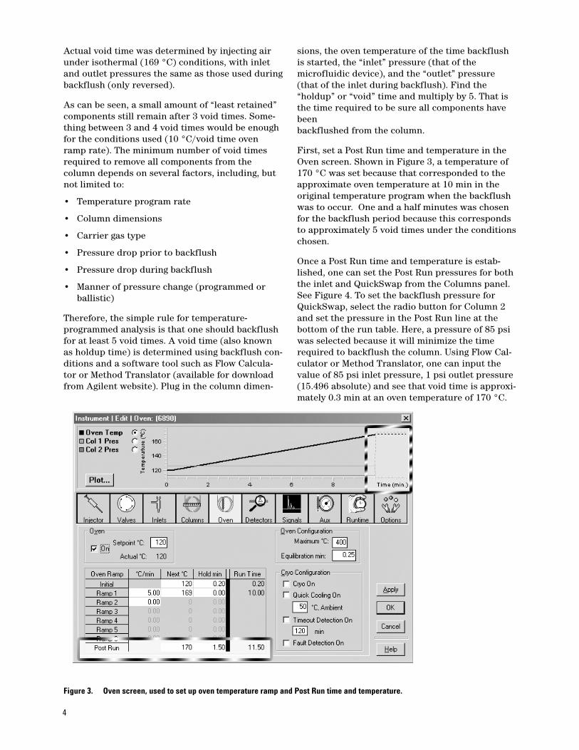
First, set a Post Run time and temperature in theOven screen. Shown in Figure 3, a temperature of170 °C was set because that corresponded to theapproximate oven temperature at 10 min in theoriginal temperature program when the backflushwas to occur. One and a half minutes was chosenfor the backflush period because this correspondsto approximately 5 void times under the conditionschosen.
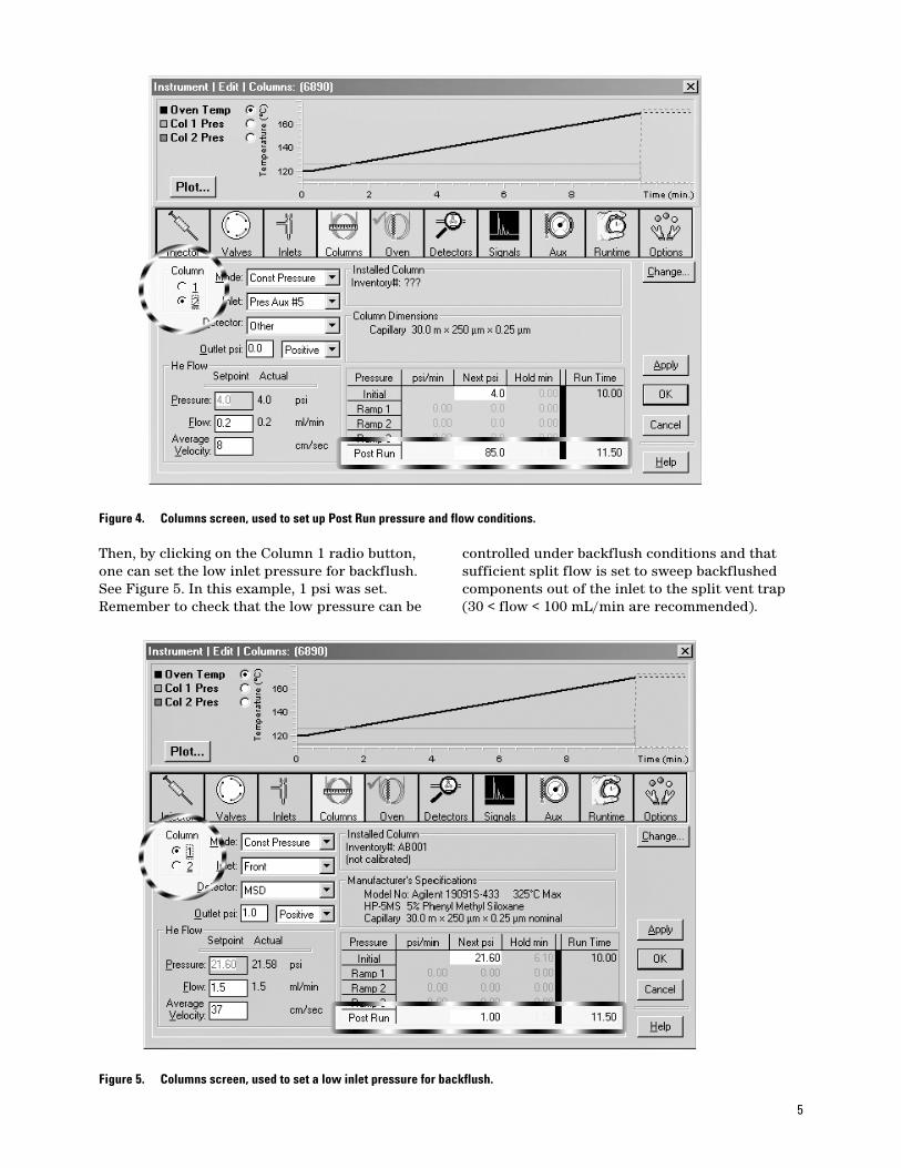
Once a Post Run time and temperature is estab-lished, one can set the Post Run pressures for boththe inlet and QuickSwap from the Columns panel.See Figure 4. To set the backflush pressure forQuickSwap, select the radio button for Column 2and set the pressure in the Post Run line at thebottom of the run table. Here, a pressure of 85 psiwas selected because it will minimize the timerequired to backflush the column. Using Flow Cal-culator or Method Translator, one can input thevalue of 85 psi inlet pressure, 1 psi outlet pressure(15.496 absolute) and see that void time is approxi-mately 0.3 min at an oven temperature of 170 °C.
Figure 3. Oven screen, used to set up oven temperature ramp and Post Run time and temperature.
5
Then, by clicking on the Column 1 radio button,one can set the low inlet pressure for backflush.See Figure 5. In this example, 1 psi was set.Remember to check that the low pressure can be
Figure 4. Columns screen, used to set up Post Run pressure and flow conditions.
controlled under backflush conditions and thatsufficient split flow is set to sweep backflushedcomponents out of the inlet to the split vent trap(30 < flow < 100 mL/min are recommended).
Figure 5. Columns screen, used to set a low inlet pressure for backflush.

6
Will backflushing through the inlet cause problems?
A common question from backflush neophytes is“Will I cause problems by backflushing high-boilingcomponents back through the inlet?” Backflushingis only done with inlets that are purged, for exam-ple, split/splitless or PTV. These inlets have beendesigned to handle all sample components whendoing split injections and when venting after split-less injection. To that end, these inlets havereplaceable split-vent traps that are designed tohandle whatever passes through the inlet. Allsample components that make it into the columnhave already passed through the inlet once; thereis no reason to believe that there would be a prob-lem arising from them passing back through theinlet a second time, as long as a reasonable splitvent (pure) gas flows to help backflushed components move to the split vent trap.
Gas Saver mode provides added independence to method
One way to ensure that a reasonable flow purgesthrough the inlet during backflush is to use GasSaver Mode. This achieves independence from boththe conditions that are used during injection andthe mode of injection (such as, splitless versussplit). Here, we did a split injection at high splitratio with high associated split flow (617 mL/min).Gas Saver was activated at 3 minutes into the run,with a split flow reduced to 75 mL/min. If GasSaver had not been used in this method, then thehigh vent flow associated with the high split ratiomay have disallowed the pressure of the inlet toget down to the 1 psi set point (there is a smallpressure drop through the split vent trap thatmight become notable at high split vent flowrates). See Figure 6.
Figure 6. Inlets screen, displaying Gas Saver settings.

7
Instrumental
Below is an example listing of conditions used toperform a Post Run backflush (such as thoseshown in the Discussions section).
Oven Front Inlet (Split/Splitless) Initial temp: 120 °C (On) Mode: SplitInitial time: 0.20 min Initial temp: 300 °C (On)
Pressure: 21.60 psi (On)Temperature Ramp for Original: Split ratio: 400:1
No. Rate Final temp Final time Split flow: 617.1 mL/min1 5.00 330 1.00 Total flow: 621.5 mL/min2 0.0 (Off) Gas saver: On
Saver flow: 75.0 mL/minPost temp: 70 °C Saver time: 3.00 minPost time: 0.00 min Gas type: HeliumRun time: 43.20 min
Temperature Ramp for Backflush:No. Rate Final temp Final time 1 5.00 169 0.00 2 0.0 (Off)
Post temp: 170 °CPost time: 1.50 minRun time: 10.00 min
Column 1 Column 2Capillary column Capillary columnModel number: Agilent 19091S-433
HP-5MS 5% phenyl methyl siloxane Max temperature: 325 °C Nominal length: 30.0 m Nominal length: 30.0 mNominal diameter: 250.00 µm Nominal diameter: 250.00 µmNominal film thickness: 0.25 µm Nominal film thickness: 0.25 µmMode: Constant pressure Mode: Constant pressurePressure: 21.60 psi Pressure: 4.00 psiNominal initial flow: 1.5 mL/min Nominal initial flow: 0.2 mL/minAverage velocity: 37 cm/sec Average velocity: 8 cm/secInlet: Front Inlet Inlet: Aux 5 Pressure ControllerOutlet: MSD Outlet: (unspecified)Outlet pressure: 1.00 psi Outlet pressure: 0.00 psi
Aux Pressure 5 Post RunDescription: QuickSwap Post Time: 1.50 minGas Type: Helium Oven Temperature: 170 °CDriving Column 2 Column 1 Pressure: 1.0 psiInitial pressure: 4.00 psi (On) Column 2 Pressure: 85.0 psi
Front InjectorSample washes: 2Sample pumps: 3Injection volume: 0.10 µLSyringe size: 5.0 µLPreinjection solvent A washes: 0Preinjection solvent B washes: 0Postinjection solvent A washes: 2Postinjection solvent B washes: 0Viscosity delay: 0 secPlunger speed: FastPreinjection dwell: 0.00 minPostinjection dwell: 0.00 min
8
For the following examples, a reference chromato-gram was acquired with no backflush. Then, analysis was repeated with a backflush at 10 min.Finally, a blank was run under full analysis condi-tions to determine if any sample components wereleft on the column.
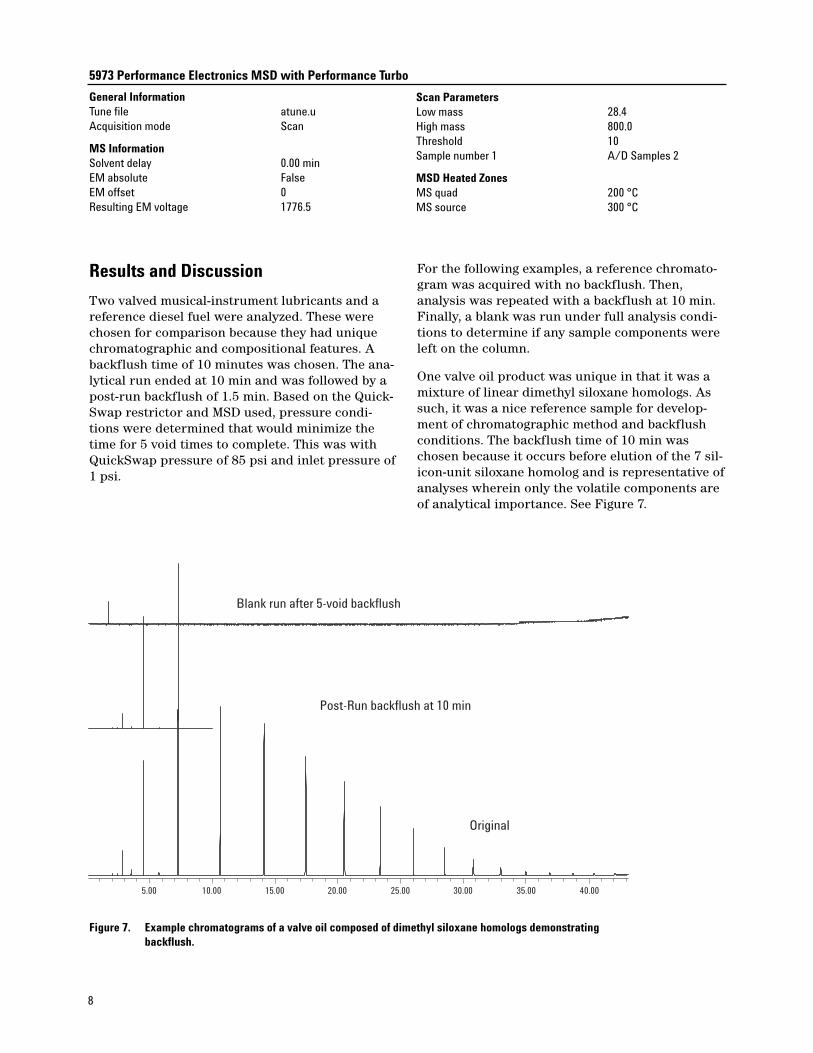
One valve oil product was unique in that it was amixture of linear dimethyl siloxane homologs. Assuch, it was a nice reference sample for develop-ment of chromatographic method and backflushconditions. The backflush time of 10 min waschosen because it occurs before elution of the 7 sil-icon-unit siloxane homolog and is representative ofanalyses wherein only the volatile components areof analytical importance. See Figure 7.
5973 Performance Electronics MSD with Performance Turbo
General InformationTune file atune.uAcquisition mode Scan
MS InformationSolvent delay 0.00 minEM absolute FalseEM offset 0Resulting EM voltage 1776.5
5.00 10.00 15.00 20.00 25.00 30.00 35.00 40.00
Original
Post-Run backflush at 10 min
Blank run after 5-void backflush
Figure 7. Example chromatograms of a valve oil composed of dimethyl siloxane homologs demonstratingbackflush.
Scan ParametersLow mass 28.4High mass 800.0Threshold 10Sample number 1 A/D Samples 2
MSD Heated ZonesMS quad 200 °CMS source 300 °C
Results and Discussion
Two valved musical-instrument lubricants and areference diesel fuel were analyzed. These werechosen for comparison because they had uniquechromatographic and compositional features. Abackflush time of 10 minutes was chosen. The ana-lytical run ended at 10 min and was followed by apost-run backflush of 1.5 min. Based on the Quick-Swap restrictor and MSD used, pressure condi-tions were determined that would minimize thetime for 5 void times to complete. This was withQuickSwap pressure of 85 psi and inlet pressure of1 psi.

9
Notice from the blank run that the 1.5 min back-flush (5 void times) was sufficient to remove allcomponents that eluted after 10 min under theoriginal conditions.
Another valve oil product was a petroleum distilla-tion cut. The initiation of backflush at 10 minutesoccurred in the thick of elution of sample compo-nents. As can be seen from the blank run, all
5.00 10.00 15.00 20.00 25.00 30.00 35.00 40.00
Original
Post-Run backflush at 10 min
Blank run after 5-void backflush
Figure 8. Chromatograms demonstrating backflush efficacy using a valve oil product composed of a petroleumdistillation cut.
remaining sample components were effectivelyremoved from the column. See Figure 8.
A diesel sample was chosen to accentuate theremoval of high boilers. The diesel had componentseluting out past 25 min. The blank run after thebackflush analysis demonstrates that all compo-nents were effectively removed during the backflush. See Figure 9.
5.00 10.00 15.00 20.00 25.00 30.00 35.00 40.00
Original
Post-Run backflush at 10 min
Blank run after 5-void backflush
Figure 9. Example chromatograms of NIST 2724b reference diesel demonstrating backflush efficacy.
10
Time Savings
For the examples shown, cycle time was improvedby both reducing run time and by stopping theoven temperature program at the time of back-flush. This allowed the oven to cool from a lowertemperature to starting conditions, saving time.See Table 3.
Table 3. Example of Time Saved Using Backflush
Run time Cool down time Total(min) (min) (min)
Original 43.2 3.47
Backflush 11.5 1.90
Savings 31.7 1.57 33.27
Approximately 31.5 min run time was saved andanother 1.5 min during cool down, for a total sav-ings of approximately 33 min. If one were to needto run multiple samples, it is clear that lab produc-tivity would significantly increase by incorporatinga backflush.
Constant Flow Mode
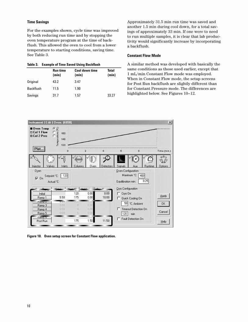
A similar method was developed with basically thesame conditions as those used earlier, except that1 mL/min Constant Flow mode was employed.When in Constant Flow mode, the setup screensfor Post Run backflush are slightly different thanfor Constant Pressure mode. The differences arehighlighted below. See Figures 10–12.
Figure 10. Oven setup screen for Constant Flow application.
11
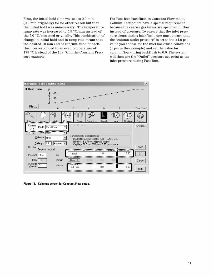
First, the initial hold time was set to 0.0 min (0.2 min originally) for no other reason but thatthe initial hold was unnecessary. The temperatureramp rate was increased to 5.5 °C/min instead ofthe 5.0 °C/min used originally. This combination ofchange in initial hold and in ramp rate meant thatthe desired 10 min end of run/initiation of back-flush corresponded to an oven temperature of 175 °C instead of the 169 °C in the Constant Pres-sure example.
For Post Run backflush in Constant Flow mode,Column 1 set points have a special requirementbecause the carrier gas terms are specified in flowinstead of pressure. To ensure that the inlet pres-sure drops during backflush, one must ensure thatthe “column outlet pressure” is set to the ≤4.0 psivalue you choose for the inlet backflush conditions(1 psi in this example) and set the value forcolumn flow during backflush to 0.0. The systemwill then use the “Outlet” pressure set point as theinlet pressure during Post Run.
Figure 11. Columns screen for Constant Flow setup.

12
For Column 1, a 1 mL/min Constant Flow wasused.
“Column 2” configuration is the same as in theConstant Pressure case. Constant Pressure modeshould be selected, with QuickSwap as the Aux #5inlet. This will allow a backflush pressure to be setduring Post Run.
In this example, 1 psig was used as the pressurefor analysis (the same as what was entered asOutlet Pressure for Column 1). A Post Run pres-sure of 85 psig was entered just as in the ConstantPressure example.
Figure 12. Columns screen for setting initial and Post Run pressure in Constant Pressure mode.

13
Some results from the above Constant Flow analysis and backflush conditions are shown inFigure 13.
For the homologous series of dimethyl siloxanes inFigure 13, the 1.5 min backflush (approximately
5.00 10.00 15.00 20.00 25.00 30.00 35.00 40.00
Original1 mL/min
Backflush at 10 min
Blank after backflush
Figure 13. Chromatograms of dimethyl siloxane homologs analyzed under Constant Flow mode conditions and backflush.
3.3 void times) was clearly sufficient to backflushall components remaining in the column at theconclusion of the 10 min run. This is confirmed inthe following example of NIST 2724b diesel fuel.See Figure 14.
5.00 10.00 15.00 20.00 25.00 30.00 35.00 40.00
Original1 mL/min
Backflush at 10 min
Blank after backflush
Figure 14. Backflush applied to diesel fuel sample NIST 2724b, analyzed under Constant Flow mode conditions.

Agilent shall not be liable for errors contained herein or for incidental or consequentialdamages in connection with the furnishing, performance, or use of this material.
Information, descriptions, and specifications in this publication are subject to changewithout notice.
© Agilent Technologies, Inc. 2006
Printed in the USAJune 12, 20065989-5111EN
www.agilent.com/chem
Figure 15 is an expanded plot of the diesel fuelexample shown in Figure 14. Notice that the base-line on the subsequent blank run after backflush isvery clean. This shows that in addition to cycletime improvements, backflushing is an excellentway of improving overall analysis quality by remov-ing all potential ghost peaks emanating from priorsample analyses.
Summary
A simple way to perform backflush with gas-phasemicrofluidic devices is described and demon-strated using the Agilent 6890 gas chromatograph.
5.00 10.00 15.00 20.00 25.00 30.00 35.00 40.00
Backflush at 10 min
Blank after backflush
Figure 15. Expanded plot of the diesel fuel example showing excellent clean baseline after backflush.
By selecting the microfluidic pressure source asthe “inlet” for “Column 2” in the Column Configu-ration screen, one can then set a backflush pres-sure and time in Post Run. Several advantagesensue, including the ability to backflush in methods that use Constant Flow mode.
For More Information
For more information on our products and services,visit our website at www.agilent.com/chem.