application note: nanomechanical tests using a nanomanipulator
TRANSCRIPT
APPLICATION NOTE [email protected]
In Situ Mechanical Testing Usingthe AutoProbe® Nanomanipulator
In situ Mechanical TestingAFM cantilevers with known spring constants can function as sensitive load sensors and are available in a wide range of values, making them versatile in principle for many different material types. By using them with a nanomanipulator to effect displacement concurrently with real-time SEM or FIB imaging, stress and strain measurements of nanostructures can be obtained. Researchers are taking advantage of the AutoProbe® nanomanipulator’s precise XYZ closed-loop motion control and resolution to effectively apply a force at a controlled rate. Strain can be measured directly from real-time FIB or SEM images [2] or by using differential image tracking (DDIT) [4].
Example 1:Determining Young’s Modulus of ZnO Nanowires [2]Quasi-static mechanical characterization of individual ZnO nanowires ranging from 200-750 nm in diameter was performed by bending the nanowires with a very soft spring (AFM cantilever) mounted to the AutoProbe® 200. In situ FIB/SEM testing allowed for real-time observation of the nanowire-tip interaction during the experiment. Manipulation was required to harvest the nanowire by van der Waal’s forces and move it to a support structure where it was secured with beam-induced deposition. With the AFM tip
P-G-ANAP-061811 © 2011 Omniprobe, Inc. All Rights Reserved (continued)
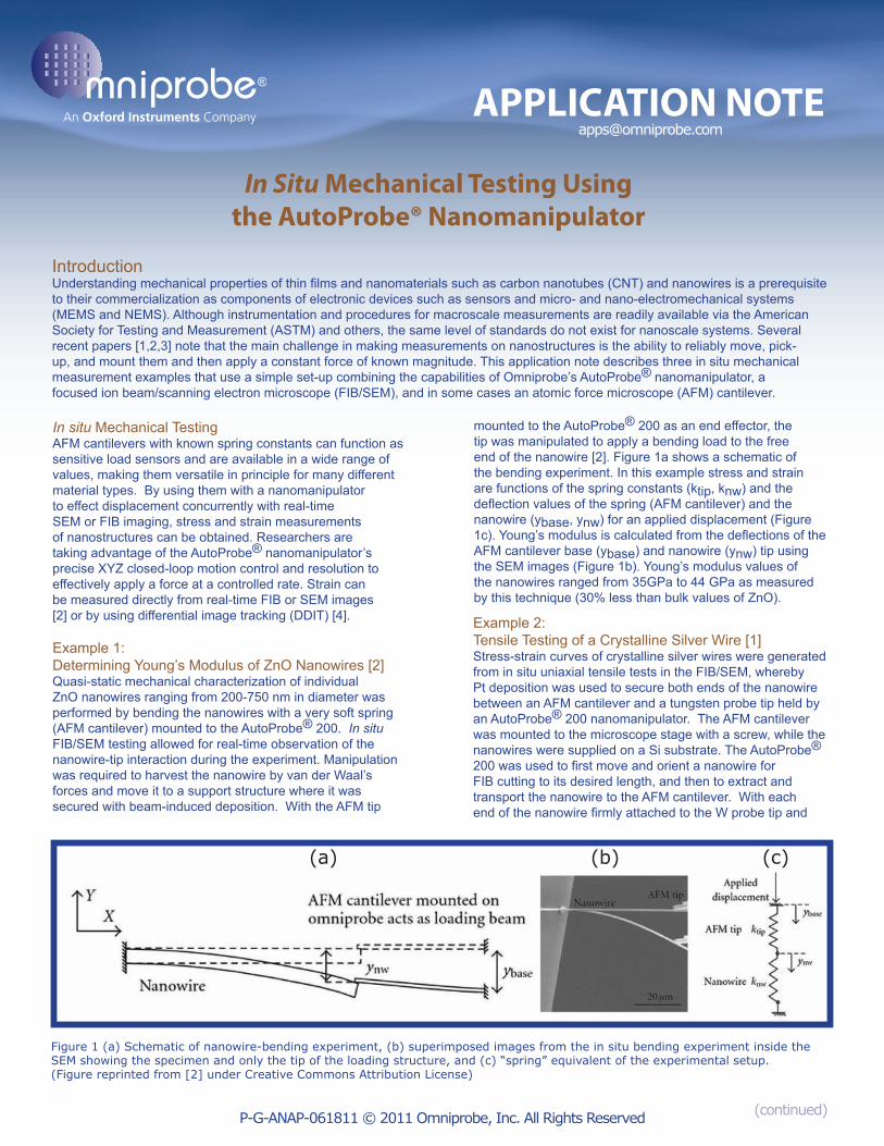
mounted to the AutoProbe® 200 as an end effector, the tip was manipulated to apply a bending load to the free end of the nanowire [2]. Figure 1a shows a schematic of the bending experiment. In this example stress and strain are functions of the spring constants (ktip, knw) and the deflection values of the spring (AFM cantilever) and the nanowire (ybase, ynw) for an applied displacement (Figure 1c). Young’s modulus is calculated from the deflections of the AFM cantilever base (ybase) and nanowire (ynw) tip using the SEM images (Figure 1b). Young’s modulus values of the nanowires ranged from 35GPa to 44 GPa as measured by this technique (30% less than bulk values of ZnO).
Example 2:Tensile Testing of a Crystalline Silver Wire [1]Stress-strain curves of crystalline silver wires were generated from in situ uniaxial tensile tests in the FIB/SEM, whereby Pt deposition was used to secure both ends of the nanowire between an AFM cantilever and a tungsten probe tip held by an AutoProbe® 200 nanomanipulator. The AFM cantilever was mounted to the microscope stage with a screw, while the nanowires were supplied on a Si substrate. The AutoProbe® 200 was used to first move and orient a nanowire for FIB cutting to its desired length, and then to extract and transport the nanowire to the AFM cantilever. With each end of the nanowire firmly attached to the W probe tip and
(a) (b) (c)
IntroductionUnderstanding mechanical properties of thin films and nanomaterials such as carbon nanotubes (CNT) and nanowires is a prerequisite to their commercialization as components of electronic devices such as sensors and micro- and nano-electromechanical systems (MEMS and NEMS). Although instrumentation and procedures for macroscale measurements are readily available via the American Society for Testing and Measurement (ASTM) and others, the same level of standards do not exist for nanoscale systems. Several recent papers [1,2,3] note that the main challenge in making measurements on nanostructures is the ability to reliably move, pick-up, and mount them and then apply a constant force of known magnitude. This application note describes three in situ mechanical measurement examples that use a simple set-up combining the capabilities of Omniprobe’s AutoProbe® nanomanipulator, a focused ion beam/scanning electron microscope (FIB/SEM), and in some cases an atomic force microscope (AFM) cantilever.
Figure 1 (a) Schematic of nanowire-bending experiment, (b) superimposed images from the in situ bending experiment inside the SEM showing the specimen and only the tip of the loading structure, and (c) “spring” equivalent of the experimental setup.(Figure reprinted from [2] under Creative Commons Attribution License)
Omniprobe - Dallas, TX 75238 - 214-572-6800P-G-ANAP-061811 © 2011 Omniprobe, Inc. All Rights Reserved
References[1] Scherer et al. Tensile Testing of Microstructures Method to Study the Mechanical Properties of Microsamples, online at Imaging and Microscopy: http://www.imaging-git.com/science/scanning-probe-microscopy/tensile-testing-microstructures. (5/13/11).[2] Manoharan, MP, AV Desai, G Neely, and MA Haque. Synthesis and Elastic Characterization of Zinc Oxide Nanowires, Journal of Nanomaterials. Article ID 849745:7pp. doi:10.1155/2008/849745(2008).[3] Zhu Y. et al. Experimental Techniques for the Mechnical Characterization of One-Dimensional Nanstructures, Exp Mech, v47:7-24. doi:10.1007/s11340-006-0406-6(2007).[4] Gianola, D. and C. Eberl. The Micro- and Nanoscale Tensile Testing of Materials, Journal of the Minerals, Metals and Materials Society, v61:24-35 (2009).[5] T. Scherer et al. An Easy Method to Study the Mechanical Properties of Microsamples, Imaging & Microscopy, Issue 1, Vol. 13, 44-47 (2011).[6] Manoharan, MP, AV Desai, and MA Haque. Fracture Toughness Characterization of Advanced Coatings, Journal of Mechanical Engineering. v19-115004 (2009).
AFM cantilever by Pt deposition, the nanowire was then ready for testing. The AutoProbe® 200 was used to apply a constant tensional force to the wire at a velocity of 0.1 µm/s until failure. To obtain side-view images during the tensile loading experiment, a movie was recorded using a 1pA ion beam. Freeze frames from the movie were used extract force and strain information by measuring the deflection of the cantilever and wire before and after stretching. Force was calculated as the product of the spring constant of the cantilever and the displacement. Strain was calculated based on measurements made on FIB images and the DDIT method described by Gianola and Eberl [4]. Stress-strain curves were plotted and showed elastic behavior until failure.
Example 3:Fracture Toughness of Ti-TiN Thin FilmSurface Coatings [6}To measure the fracture toughness of multi-layered thin film stacks, the stacks need to be isolated from the substrates on which they are grown. This can be accomplished using FIB/SEM in-situ extraction and lift-out [6] in a process very similar to in situ TEM sample preparation. After extraction the lamella must be mounted to a secondary substrate and prepared for
the test by milling a notch in the top surface to serve as a fracture propagation point. To measure a 300 nm thick cross-section of Ti-TiN films, the AutoProbe® was used to apply a load at a displacement of 0.5 μm min-1 until failure. With stiffness of the tungsten probe tip and the total displacement known, fracture toughness along and across the films was calculated. The ability to monitor the experiment continuously during the loading process and the applicability of this method to a wide variety of materials was noted in this study [6].
ConclusionCharacterization of properties, such as the size, shape, crystal orientation, and composition of nanoscale objects is simple in comparison to measuring their mechanical properties. This application note provides examples of mechanical measurements made using an AFM cantilever, nanomanipulator and FIB/SEM with gas chemistry for the material removal, gluing steps and image acquisition. For best results, high-quality welding of the nanowire to the cantilever and/or nanomanipulator and the ability to capture accurate data for the applied force and resulting displacement are necessary. The references in this application note contain many additional details on mechanical measurements of nanoscale materials.
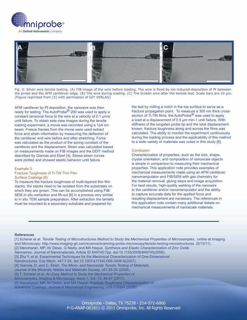
Fig. 2: Silver wire tensile testing. (A) FIB image of the wire before loading. The wire is fixed by ion-induced-deposition of Pt between the probe and the AFM cantilever edge. (B) The wire during loading. (C) The broken wire after the tensile test. Scale bars are 10 µm.(Figure reprinted from [5] with permission of GIT VERLAG)