application of an alternative mesh morphing method on the … · 2019-11-22 · rbrh, porto alegre,...
TRANSCRIPT

Revista Brasileira de Recursos HídricosBrazilian Journal of Water ResourcesVersão On-line ISSN 2318-0331RBRH, Porto Alegre, v. 24, e32, 2019Scientific/Technical Article
https://doi.org/10.1590/2318-0331.241920180102
1/12
This is an Open Access article distributed under the terms of the Creative Commons Attribution License, which permits unrestricted use, distribution, and reproduction in any medium, provided the original work is properly cited.
Application of an alternative mesh morphing method on the numerical modeling of oscillating wave surge converters
Aplicação de uma metodologia alternativa de deformação de malhas na modelagem numérica de conversores oscilantes por translação de ondas
Guilherme Fuhrmeister Vargas1 and Edith Beatriz Camaño Schettini1
1Instituto de Pesquisas Hidráulicas, Universidade Federal do Rio Grande do Sul, Porto Alegre, RS, BrasilE-mails: [email protected] (GFV), [email protected] (EBCS)
Received: June 15, 2018 - Revised: February 15, 2018 - Accepted: May 22, 2019
ABSTRACT
A technology capable of converting the horizontal motion of the ocean waves into energy by the application of a flap-piston system has been improved over the last few years, this device is known as oscillating wave surge converter. This system has great potential, already proven, for electric power generation. The computational fluid dynamics is one of the most used tools for the study of wave energy converters. In this context, the present paper proposes the application of an alternative mesh morphing method to represent the hydrodynamics of these devices, which is based on a bottom that oscillates with the converter, leading the flap to reach high inclinations without causing numerical divergences. The study is performed using the OpenFOAM computational code and its extension OLAFOAM. These are based on Reynolds Average Navier Stokes (RANS) turbulence modeling and the Volume of Fluid method (VOF) for the free surface representation, which are applied to a bidimensional model, allowing the numerical modeling of the converter. The proposed method presented good agreement of the results when compared to the experimental studies in similar hydrodynamic cases. The methodology based on a moving bottom presented relative differences, concerning the method that considers the bottom as fixed, between 4% and 17% for the cases where the flap is near to the ocean bottom and up to 8% for cases where it is further away.
Keywords: Oscillating wave surge converters; OpenFOAM; OLAFOAM; RANS; Mesh morphing method.
RESUMO
Uma das tecnologias capazes de explorar a energia das ondas, baseada na captação das componentes horizontais do movimento destas, aliada a um sistema placa-pistão, vem experimentando um notável desenvolvimento ao longo dos últimos anos, tal dispositivo é conhecido como conversor oscilante por translação de ondas. Este possui um grande potencial, já comprovado, de geração de eletricidade. Uma das maneiras mais utilizadas para a análise destes conversores consiste na aplicação de ferramentas de modelagem numérica computacional. Neste contexto, o presente trabalho propõe a aplicação de uma metodologia numérica alternativa de deformação da malha de cálculo para representar a hidrodinâmica destes dispositivos, a qual está baseada em um fundo que oscila juntamente com o conversor, permitindo que este atinja inclinações elevadas, sem ocasionar divergências numéricas. O estudo é realizado pela aplicação do código computacional OpenFOAM, em conjunto com sua extensão OLAFOAM, que, através da metodologia Volume of Fluid (VOF), para a representação da superfície livre, e do método das médias de Reynolds (RANS), para a modelagem da turbulência, possibilita a simulação bidimensional da dinâmica do conversor considerado. O método proposto mostrou boa concordância e representatividade dos resultados, quando comparados a estudos experimentais, presentes na literatura, em situações hidrodinâmicas similares. Além disto, a metodologia baseada em um fundo móvel apresentou diferenças relativas, em relação ao método que considera o fundo como fixo, entre 4% e 17% para casos de placa muito próximos ao fundo do domínio e de até 8% para os casos onde esta encontra-se mais afastada.
Palavras-chave: Conversores de energia por translação de ondas; OpenFOAM; OLAFOAM; RANS; Método de deformação de malha.

RBRH, Porto Alegre, v. 24, e32, 2019
Application of an alternative mesh morphing method on the numerical modeling of oscillating wave surge converters
2/12
INTRODUCTION
The search for new technologies and resources for the electric generation from renewable sources has been the main goal of many engineers and scientists, which are focused on the exploitation of effective resources with considerable energy potential and that have a minimal environmental impact. In this context, the main technologies currently under development are based on wind, solar and biomass energies, while other sources of energy are still little explored (INTERNATIONAL RENEWABLE ENERGY AGENCY, 2017).
Many countries like Portugal, Spain, China, Canada, United States, United Kingdom, and Ireland, are investing in the development and research of technologies capable of converting the ocean waves energy on electricity (OCEAN ENERGY SYSTEMS, 2018). The interest of these countries in this type of energy is justified by the fact that the waves have a theoretical average energy potential of approximately 29500 TWh/year (WORLD ENERGY COUNCIL, 2016), higher than the total electric energy consumed in 2016 (INTERNATIONAL ENERGY AGENCY, 2018). However, despite technological advances on the development of resources capable of harnessing wave energy, few technologies are in the commercial stage (ADERINTO; LI, 2018). According to MacGillivray et al. (2013), this situation is related to the installation and energy transmission problems, to the maintenance, to socioeconomic factors and variability in the wave climate concerning the operation of the devices. These facts justify the importance of the search for engineering solutions and in the understanding and performance prediction of the converters in real operating cases (UIHLEIN; MAGAGNA, 2016).
One of the main technologies responsible for converting the horizontal wave motion into electrical energy, which is in the pre-commercial phase of development, is known as the Oscillating Wave Surge Converter – OWSC (PECHER; KOFOED, 2017). These devices can be placed at different depths and have a relatively simple operating principle compared to other wave-conversion technologies (DHANAK et al., 2016).
The OWSC’s have the principle of conversion based on the back and forth movement of a flap (which is less dense than water) that drives a high-pressure fluid in a secondary hydraulic system by a piston, moving a turbine responsible for the electricity generation (Figure 1).
Over the past few years, some papers have focused on the study of this type of technology, among them is the work of Whittaker and Folley (2012), which presents one of the main results of experimental studies conducted in the Queen’s University Belfast wave tank. In this work, the main parameters related to the hydrodynamics of an Oyster type device are presented, which consists of a partially submerged flap extending from the ocean bottom to above the water surface, similar to the one represented in Figure 1. Renzi and Dias (2013) propose a mathematical model, based on the boundary element method, to enable the analysis of the converter by numerical modeling. The same authors report that the oscillating wave surge converters reach the highest potential in shorter wave periods, highlighting the great efficiency of this type of technology on the generation of electricity. Rafiee et al. (2013) and Wei et al. (2015) present the main numerical and experimental results on the OWSC’s, obtained by the analysis of the angular
amplitudes and pressures measured, providing a comparison between the numerical results and the experimental studies. Recently, Dias et al. (2017) present an overview of the main technological advances made possible by experimental studies, including some numerical methodologies applied to represent the dynamics of the converters. This work also contemplates the application of numerical modeling in the study of an array of converters under different wave conditions. Schmitt and Elsäßer (2017) studied the scale effect in reduced models of OWSC’s by numerical modeling. This work allows concluding that the significance of the errors committed when using the Froude scale depends mainly on the geometry and shape of the flaps and can hide areas of vortex formation. A methodology that uses a mathematical model independent of the numerical mesh modification was proposed by Mottahedi, Anbarsooz and Passandideh-Fard (2018), however, although it presents satisfactory results, it is related to a certain difficulty in the mathematical implementation of the involved equations.
In general, the literature on oscillating wave surge converters highlighted the important role of numerical modeling on the study of these devices. On the other hand, they also demonstrate that there are gaps to be explored in order to allow a more realistic assessment of the OWSC performance in various operating situations, such as hydrodynamic modeling of several converters of the same type or different working together, the consideration of the currents effects combined with the wave dynamics, and simulations that allow a close relation between OWSC’s geometry, wave climate, installation depth and generated energy.
Considering the importance of numerical modeling in the understanding and analysis of the converters, the development and application of alternative numerical methodologies make the study of this technology more accessible, in terms of the existing computational capacity, as well as of the analyzed geometric and flap position aspects. Schmitt and Elsaesser (2015) point out three main methods for modeling OWSC’s: Arbitrary Mesh Interface (AMI), Mesh modification at each time step (Remeshing) and Mesh Morphing. The first one is based on the use of two independent domains that interact with each other, one is responsible for the waves hydrodynamics and the other for the movement of the rigid body. The second methodology is associated with a reconstruction of the mesh at each time step to adapt it to the position reached by the moving body; such application usually results in a high computational cost. The mesh morphing method usually already comes included in the package of solvers of most computational codes, avoiding later mathematical implementations.
Figure 1. Scheme of operation and power generation of an OWSC (adapted from OpenEI, 2018).

RBRH, Porto Alegre, v. 24, e32, 2019
Vargas and Schettini
3/12
This last method corresponds to one of the simplest techniques for modeling the dynamics of the converter, which justifies its importance in terms of practicality and relatively low computational costs when compared to other methodologies. The principle of the technique consists of deforming the small control volumes that compose the domain (referring to the Finite Volume discretization method) to describe the rigid body movement, preserving its geometry (OPENFOAM FOUNDATION, 2016). On the other hand, this methodology presents numerical instabilities in the cases where the flap of an OWSC reaches very inclined positions, which are related to the angular mesh elements that are formed (Figure 2). The problem is even greater in cases where it is desired to model converters that are very close to the bottom, such as the Oyster device, resulting in numerical instabilities on the usual operating cases of OWSC’s (SCHMITT; ELSAESSER, 2015).
In this context, it is necessary to apply an alternative methodology, using the mesh morphing method, which allows the study of the OWSC dynamics in extreme operating situations (with high inclination angles), without extensive numerical implementations and numerous tests existing in the validation stage.
This work proposes the use of a two - dimensional numerical model based on a moving bottom, which oscillates according to the flap, allowing the converter to be modeled in several operating cases. Therefore, an evaluation of the appropriate velocity boundary condition to be used on the surface of the oscillating flap is performed, followed by a comparison between the results found using the proposed numerical model and those obtained by experimental tests. In the last part of the work, a study is performed comparing the fixed bottom method to the proposed oscillating bottom methodology.
NUMERICAL METHODOLOGY
The simulations presented in this work were performed by the open source code OpenFOAM v. 4.1, programmed in the C++ language and based on finite volume discretization. This code allows the user to program new equations or change existing routines, including the possibility of applying up to fourth order precision schemes.
The Navier-Stokes and Continuity equations govern the flow and are solved numerically by the computational code. These
expressions can be written in tensor notation, constituting the numerical method of modeling the turbulence known as RANS - Reynolds Average Navier Stokes (CHENG et al., 2003):
' 'i i ij i i j
j i j j
u u u1 pu g u ut x x x x
νρ
∂ ∂ ∂∂ ∂+ = − + − ∂ ∂ ∂ ∂ ∂
(1)
i
i
u 0x∂
=∂
(2)
where xi represents the spatial coordinates, t the time, ui the velocity vector, gi the gravity, p the total pressure, ρ the specific mass of the water and í its kinematic viscosity. The term ' '
i ju u represents the Reynolds tensor, which can be solved by applying a turbulent viscosity, which is calculated by a turbulence model. In the present study, the К-ω SST model (MENTER et al., 2003) was applied. This turbulence model is recommended to the cases where the characteristics of the flow close to the solid boundaries and in the free stream regions must be satisfactorily represented.
The free surface is modeled by the Volume of Fluid (VOF) method, which consists in assigning a value equal to “1” for a cell filled by water and a value equal to “0” for a cell composed by air. The interface is identified as an intermediate value, which is represented by an artificial compression, resulting in a term that is added to the transport equation and only becomes active on the water surface region (HIGUERA, 2016).
The rigid body motion can be described by the equation analogous to the mass-spring system, presented by Renzi et al. (2012):
²²m tI C R
t tq q q∂ ∂+ + = Μ
∂ ∂ (3)
where mI represents the mass moment of inertia of the moving body, q the angular amplitude reached by the flap (considering as initial reference the perpendicular position to the horizontal), C is the damping coefficient applied to the device, R is the moment of restoration due to buoyancy and Mt the total moment acting on the flap.
Calculation domains and flap dimensions
Two different numerical domains were used, the first one is applied to the numerical validation and the verification of the best boundary condition to be used on the oscillating flap, and the second domain is used to perform the following simulations, which aim to compare the oscillating bottom methodology to an analogous case, but with a fixed bottom. The first domain is based on the dimensions and geometry present in the Rafiee et al. (2013) and Wei et al. (2015) papers, which have the dimensions presented in Figure 3. The flap dimensions applied to the first domain simulations are represented in Figure 4.
The second domain (Figure 5) is applied to the final simulations and presents a simple prismatic geometry. The flap considered in these cases presents the dimensions represented in Figure 6.
Figure 2. Detail of the mesh elements being deformed to represent the rigid body dynamics.

RBRH, Porto Alegre, v. 24, e32, 2019
Application of an alternative mesh morphing method on the numerical modeling of oscillating wave surge converters
4/12
Numerical mesh and discretization conditions applied to the simulations
The numerical mesh, applied on the two-dimensional numerical models discussed in this work, is structured, which facilitates the treatment of the free surface and the converter dynamics. The discretization, applied to all considered cases, approaches the mesh elements as squares of sides equal to 0.04 m in the horizontal (Δx) and vertical (Δy) directions.
The numeric grid is generated by the snappyHexMesh solver, present in the OpenFOAM code. This tool consists of trimming the shape of a solid body from an initial mesh, making this methodology very useful in cases of objects with large curvatures and complex geometries (OPENFOAM FOUNDATION, 2016).
The value of 0.01 s was adopted for the initial time step (Δt). During the simulation, it is allowed to be modified as the mesh morphs to follow the OWSC flap movement, allowing the Courant number (related to numerical stability) to remain less than 1.
Initial and boundary conditions
The boundaries of the computational domains (Figures 3 and 5) can be divided into an inlet, an outlet, a “type a” bottom, a “type b” bottom (which moves in cases where the bottom mesh deformation is allowed), a top and the OWSC flap (Figure 7).
The no-slip boundary condition is imposed on the bottom and the flap. On the outlet, a sponge layer condition is applied, whose function is to absorb the incident waves and avoid their reflection. On the inlet region and at the top of the domain respectively, the conditions of generation of regular waves and free outflow are applied. The Table 1 represents the applied boundary conditions, with their respective names in the OpenFOAM code.
The initial condition applied for velocity and pressure is the zero internal field. The vertical is assumed to be the initial position of the flap movement.
Figure 3. Dimensions of the computational domain used in the numerical verification stage.
Figure 4. Dimensions of the flap used in the first domain simulations.
Figure 5. Dimensions of the computational domain used in the comparative studies between the moving and the fixed bottom.
Figure 6. Dimensions of the flap used in the numerical simulations of the second domain.

RBRH, Porto Alegre, v. 24, e32, 2019
Vargas and Schettini
5/12
Important considerations
The hydrodynamics, generation, and absorption of the regular progressive waves applied to the studied cases are implemented in the main code by the extension known as OLAFOAM (HIGUERA, 2016). This one adds two new solvers to the main code: one applicable to the cases where no body motion is present (olaFoam) and another to the cases where some rigid body dynamics (olaDyMFoam) exists, the latter being the one
adopted for the present work. Both use the VOF methodology for the free surface representation, the solution is calculated by the MULES (Multidimensional Universal Limiter for Explicit Solution) method. The velocities and pressures are obtained by the PIMPLE (Pressure Implicit with Splitting of Operators) and SIMPLE (Semi-Implicit Method for Pressure-Linked Equations) algorithms, which guarantee the convergence of results (OPENFOAM FOUNDATION, 2016).
The waves are modeled by the fifth-order Stokes theory, which is adequate for the analyzes due to the non-linearity of the considered waves. The hydrodynamics is represented by a two-dimensional model, which solves the Navier-Stokes and continuity equations in two dimensions. The 2D model, according to Wei et al. (2016), is suitable for a more general study on the hydrodynamics of an OWSC, and the three-dimensional model is recommended for more complex analyzes since it demands higher computational costs.
The rigid body motion is calculated and controlled by a dynamic solver, denominated dynamicMotionSolverFvMesh, which governs the mesh changes according to the flap movement. The solvers responsible for controlling the modifications of the numerical mesh are the displacementSBRStress (which requires the condition sixDoFRigidBodyDisplacement as a boundary condition in the “PointDisplacement” file) and sixDoFRigidBodyMotion, which implies on using the “calculated” condition as a boundary condition on the file “PointDisplacement” (OPENFOAM WIKI, 2016). The first solver is applied to the fixed-bottom simulations and the second to the cases where the bottom oscillates according to the flap movement.
A specific mass of 620.30 kg/m3 was adopted to the simulated flaps, based on the Rafiee et al. (2013) and Wei et al. (2015) papers. The mass moment of inertia used for the flaps presented in Figures 4 and 6 are, respectively, 2.90 kg.m2 and 0.86 kg.m2. All the converters are in the geometric scale of 1:25, which is the same applied to the experimental works (studied in reduced models) used for the numerical verification of the code.
Cases of analysis were chosen, based on the previously mentioned experimental works, to validate the computational model. The values obtained in two pressure sensors and the water level in two level probes (Figure 8), whose coordinates are presented in Table 2, were considered.
RESULTS AND DISCUSSION
Initially, tests were performed to verify which velocity boundary condition would be most appropriate to be used on the oscillating flap. From this result, a numerical verification of the code is realized for the fixed bottom and the deformable bottom cases. Final comparisons were performed to evaluate the differences in the use of oscillating bottom methodology, verifying if this method represents an alternative for the cases where the flap reaches angular positions very close to the bottom of the domain, which would cause numerical instabilities on the fixed bottom cases. To complement the study, some statistical parameters are adopted, allowing the identification of similarities and differences in the considered methodologies.
Table 1. Velocity and pressure boundary conditions applied on the OpenFOAM code.
Contorno Velocidade Pressãoflap Variable1 fixedFluxPressure“a” type bottom noSlip fixedFluxPressure“b” type bottom noSlip fixedFluxPressureinlet waveVelocity fixedFluxPressureoutlet waveAbsorbtion2DVelocity zeroGradienttop pressureInletOutletVelocity totalPressureDomain sides Empty Empty1The velocity boundary condition changes according to the considered case, the considerations are detailed in the section “Important considerations”.
Figure 7. Representation of the boundaries used in the numerical simulations.
Figure 8. Location of water level probes and pressure sensors used in numerical validations.
Table 2. Coordinates of water level probes and pressure sensors.X (m) Y (m) Z (m)
Water level probe 1 3.99 0.52 0.71Water level probe 2 8.92 0.52 0.71Pressure sensor 1 9.76 0.52 0.50Pressure sensor 2 9.76 0.52 0.70
RBRH, Porto Alegre, v. 24, e32, 2019
Application of an alternative mesh morphing method on the numerical modeling of oscillating wave surge converters
6/12
Validation of the velocity boundary condition
On this stage, the noSlip, slip, and movingWallVelocity boundary conditions were tested, the latter is usually recommended for dynamic cases, according to the OpenFOAM Foundation (2016).
For the numerical verification, the domain of Figure 3 and the flap of Figure 4 were applied, the water level was adjusted in 0.71 m for this case. The considered wave height (H) and the wave period (T) are, respectively, 0.25 m (equivalent to a measured height of 0.12 m at the water level probe 1) and 2.00 s, both invariant for these cases.
The bottom was considered as fixed, with the flap foundation (which height is equal to 0.16 m, presented in Figure 4) being neglected, causing small water flow through the lower part of the OWSC, to allow the mesh deformation in this region.
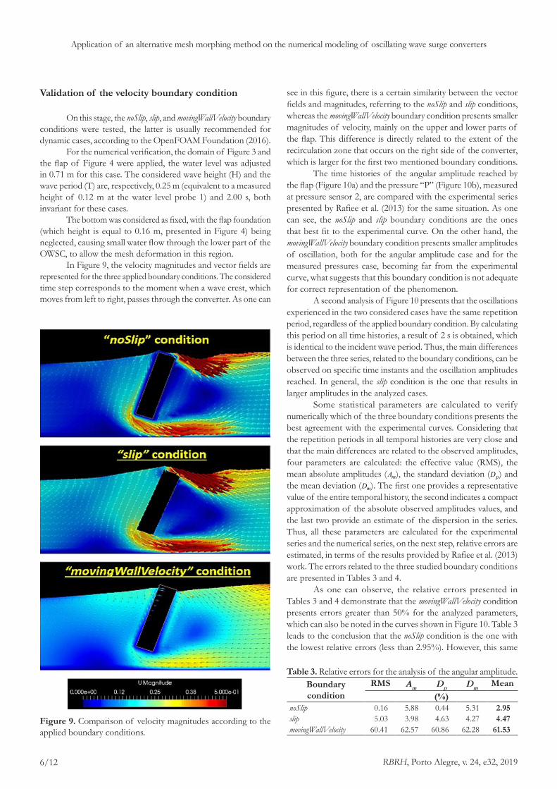
In Figure 9, the velocity magnitudes and vector fields are represented for the three applied boundary conditions. The considered time step corresponds to the moment when a wave crest, which moves from left to right, passes through the converter. As one can
see in this figure, there is a certain similarity between the vector fields and magnitudes, referring to the noSlip and slip conditions, whereas the movingWallVelocity boundary condition presents smaller magnitudes of velocity, mainly on the upper and lower parts of the flap. This difference is directly related to the extent of the recirculation zone that occurs on the right side of the converter, which is larger for the first two mentioned boundary conditions.
The time histories of the angular amplitude reached by the flap (Figure 10a) and the pressure “P” (Figure 10b), measured at pressure sensor 2, are compared with the experimental series presented by Rafiee et al. (2013) for the same situation. As one can see, the noSlip and slip boundary conditions are the ones that best fit to the experimental curve. On the other hand, the movingWallVelocity boundary condition presents smaller amplitudes of oscillation, both for the angular amplitude case and for the measured pressures case, becoming far from the experimental curve, what suggests that this boundary condition is not adequate for correct representation of the phenomenon.
A second analysis of Figure 10 presents that the oscillations experienced in the two considered cases have the same repetition period, regardless of the applied boundary condition. By calculating this period on all time histories, a result of 2 s is obtained, which is identical to the incident wave period. Thus, the main differences between the three series, related to the boundary conditions, can be observed on specific time instants and the oscillation amplitudes reached. In general, the slip condition is the one that results in larger amplitudes in the analyzed cases.
Some statistical parameters are calculated to verify numerically which of the three boundary conditions presents the best agreement with the experimental curves. Considering that the repetition periods in all temporal histories are very close and that the main differences are related to the observed amplitudes, four parameters are calculated: the effective value (RMS), the mean absolute amplitudes ( mA ), the standard deviation ( pD ) and the mean deviation ( mD ). The first one provides a representative value of the entire temporal history, the second indicates a compact approximation of the absolute observed amplitudes values, and the last two provide an estimate of the dispersion in the series. Thus, all these parameters are calculated for the experimental series and the numerical series, on the next step, relative errors are estimated, in terms of the results provided by Rafiee et al. (2013) work. The errors related to the three studied boundary conditions are presented in Tables 3 and 4.
As one can observe, the relative errors presented in Tables 3 and 4 demonstrate that the movingWallVelocity condition presents errors greater than 50% for the analyzed parameters, which can also be noted in the curves shown in Figure 10. Table 3 leads to the conclusion that the noSlip condition is the one with the lowest relative errors (less than 2.95%). However, this same
Figure 9. Comparison of velocity magnitudes according to the applied boundary conditions.
Table 3. Relative errors for the analysis of the angular amplitude.Boundary condition
RMS Am
Dp
Dm
Mean(%)
noSlip 0.16 5.88 0.44 5.31 2.95slip 5.03 3.98 4.63 4.27 4.47movingWallVelocity 60.41 62.57 60.86 62.28 61.53

RBRH, Porto Alegre, v. 24, e32, 2019
Vargas and Schettini
7/12
condition presents errors greater than the slip condition for the pressure sensor case, according to Table 4.
Considering the analysis of the curves presented in Figure 10b, instants where the numerical results are distant from the experimental values are observed, but, in general, follow the same behaviors. Similar discrepancies can be found on the Rafiee and Dias (2013) paper. The authors attribute the discrepancies between the numerical and experimental results for the pressure sensors case to the fact that the used mathematical model is two-dimensional. The same work emphasizes that three-dimensional simulations are necessary for more detailed studies of the pressures, whereas 2D modeling is reasonably adequate to the more general studies of the OWSC’s, such as the analyses discussed in the present work.
Based on the results obtained in this first verification, as well as the fact that the angular amplitude plays an important role in the evaluation of the converter dynamics (PATHAK et al., 2017), the noSlip condition is adopted as the most adequate for the following simulations.
Numerical validation of the fixed and moving bottom methodologies
For this numerical verification, the first domain (present in Figure 3) is applied, with a depth of 0.71 m and with a height and wave period, equal to respectively 0.25 m and 2 s. The objective of these tests is to validate the technique that allows the “type b” bottom deformation, as well as to compare this methodology to that method in which the bottom remains static (this condition was applied on the previous section), which is theoretically more realistic.
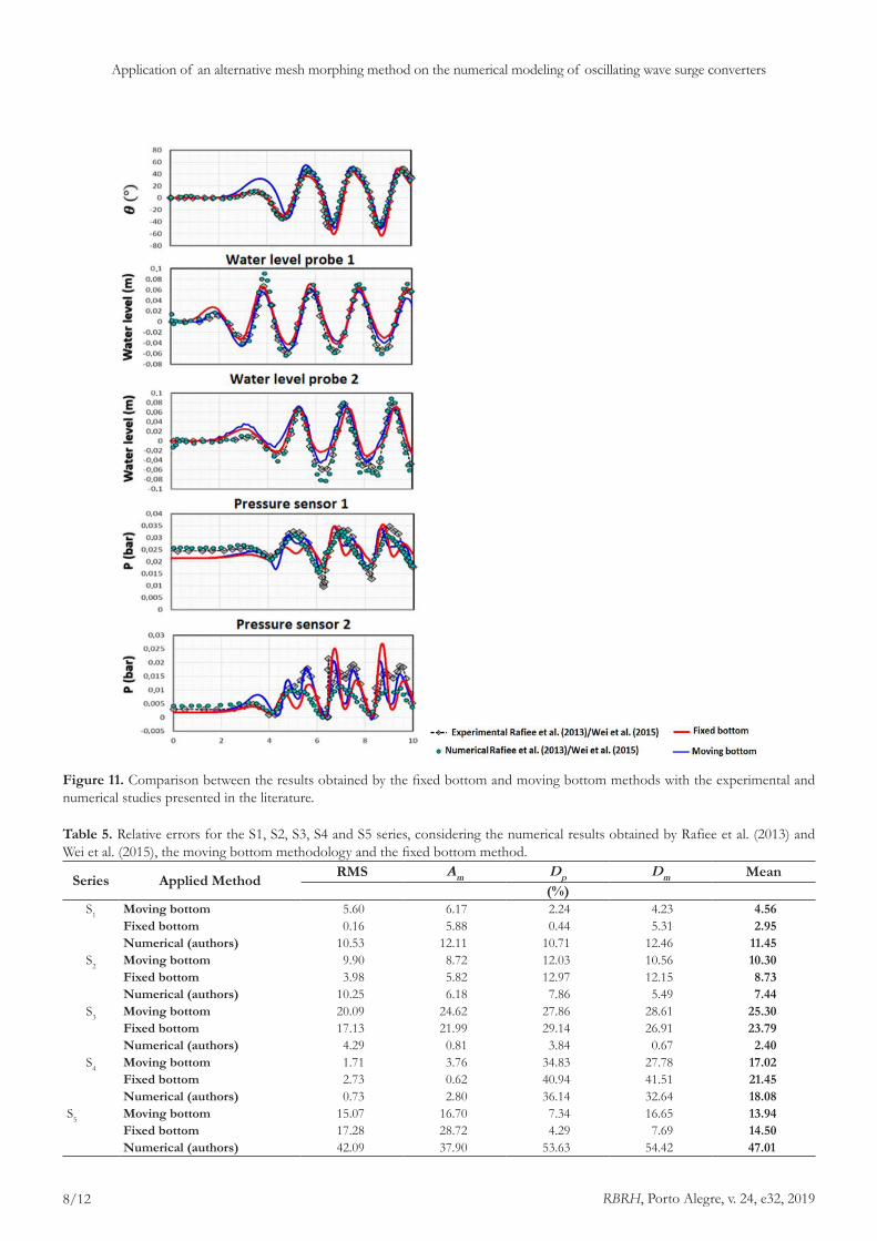
The angular amplitude of the flap, the water level probes and the pressure sensors described in Table 2 were analyzed for both models. The results are presented, together with the experimental and numerical data of the authors previously referenced, in Figure 11.
The statistical parameters of calculation used in the previous verification are also applied in these cases, to quantify how close are the numerical results to the experimental ones presented in the literature. Table 5 presents the relative errors, referring to these parameters, for the time histories of angular amplitude (S1), water level probe 1 (S2), water level probe 2 (S3), pressure sensor 1 (S4) and pressure sensor 2 (S5).
The considered table leads to the conclusion that, for the S1 case, both methodologies present relative errors less than
Figure 10. Comparison of the results obtained by applying different velocity boundary conditions, (a) considering the angular amplitude reached by the flap and (b) the pressure measured on the pressure sensor 2.
Table 4. Relative errors for the analysis of the pressure sensor 2.Boundary condition
RMS Am
Dp
Dm Mean
(%)noSlip 17.28 28.72 4.29 7.69 14.50slip 10.60 20.92 9.34 1.23 10.52movingWallVelocity 58.74 59.71 56.87 57.53 58.22
RBRH, Porto Alegre, v. 24, e32, 2019
Application of an alternative mesh morphing method on the numerical modeling of oscillating wave surge converters
8/12
Figure 11. Comparison between the results obtained by the fixed bottom and moving bottom methods with the experimental and numerical studies presented in the literature.
Table 5. Relative errors for the S1, S2, S3, S4 and S5 series, considering the numerical results obtained by Rafiee et al. (2013) and Wei et al. (2015), the moving bottom methodology and the fixed bottom method.
Series Applied Method RMS Am
Dp
Dm Mean
(%)S1 Moving bottom 5.60 6.17 2.24 4.23 4.56
Fixed bottom 0.16 5.88 0.44 5.31 2.95Numerical (authors) 10.53 12.11 10.71 12.46 11.45
S2 Moving bottom 9.90 8.72 12.03 10.56 10.30Fixed bottom 3.98 5.82 12.97 12.15 8.73Numerical (authors) 10.25 6.18 7.86 5.49 7.44
S3 Moving bottom 20.09 24.62 27.86 28.61 25.30Fixed bottom 17.13 21.99 29.14 26.91 23.79Numerical (authors) 4.29 0.81 3.84 0.67 2.40
S4 Moving bottom 1.71 3.76 34.83 27.78 17.02Fixed bottom 2.73 0.62 40.94 41.51 21.45Numerical (authors) 0.73 2.80 36.14 32.64 18.08
S5 Moving bottom 15.07 16.70 7.34 16.65 13.94Fixed bottom 17.28 28.72 4.29 7.69 14.50Numerical (authors) 42.09 37.90 53.63 54.42 47.01

RBRH, Porto Alegre, v. 24, e32, 2019
Vargas and Schettini
9/12
10%, which the most significative error is associated with the moving bottom method. However, when this curve is verified on the first graph of Figure 11, this difference is attributed to the initial simulation conditions. From the comparison between the series presented on S1 case, one can observe that the methods applied in this work lead to average relative errors lower than the numerical results obtained by Rafiee et al. (2013) and Wei et al. (2015). The fixed bottom methodology presents the lowest mean relative error for the water level probe 1 (S2), while the oscillating bottom methodology provides a maximum relative error of 12% for this case. For the case S3, the moving bottom method results in a greater average relative error, with the maximum relative error close to 29% for this method. From the cases S2 and S3, which represent the studies on water level probes, it is observed that the average relative errors, obtained numerically by the authors, are relatively smaller than the present methodologies. This fact demonstrates that 3D numerical models (as is the case of the one used in the referenced papers) are more adequate than two-dimensional models for the analysis of water levels. Table 5 also allows concluding that pressure sensors (cases S4 and S5) present the highest average relative errors, which can be related to the same reasons previously discussed in the present work. However, for these cases, the moving bottom methodology demonstrates a better agreement with the experimental results than the fixed bottom method and the numerical results presented in the literature, especially for the S5 case. This behavior can also be observed in the graph located at the bottom of Figure 11.
The numerical values obtained by the two applied methodologies are satisfactory when compared to the numerical results presented by Rafiee et al. (2013) and Wei et al. (2015) for a similar situation. Errors of the same or higher order may be noted in those works, similar to the ones observed in the present study.
In general, the two methodologies applied in this work present a range of errors expected for the two-dimensional numerical modeling of the converters, providing similar results, according to the previous graphical and statistical analysis. Thus, one can also conclude that small spaces in the lower part of the converter flap (close to 33% of the flap height) do not result on significant different values from the case where flow under the device is not allowed (such as the case of the moving bottom methodology).
Verification of the moving bottom method, according to the distance from the flap to the domain bottom.
The domain layout and flap geometry considered in the following simulations have the dimensions presented in Figures 5 and 6. The applied water level, period and wave height (concerning the generation zone) are 0.56 m, 2.4 s, and 0.12 m, corresponding to 14 m, 12 s, and 3 m, in real scale.
In order to evaluate if the moving bottom methodology causes significant changes on the OWSC modeling (concerning the cases where the converter is very close to the domain bottom), when compared to the fixed bottom method, five “a” openings were tested (Figure 12). Thus, it becomes possible to estimate the
rigid body movement and the respective hydrodynamic conditions in cases close to situations where the more realistic fixed-bottom methodology would fail.
Figure 13 presents a comparison between the velocity fields in three instants of a simulation, considering the case of distance equal to 0.05 m. It is possible to observe the movement of the OWSC flap, from left to right, at the moment of a wave crest pass through the converter. There is also a certain similarity between the two methodologies, including the similarities on the flap angular amplitudes.
A comparison between the time histories of some important variables in the dynamics of an OWSC (such as angular amplitude, angular velocity “ω” and horizontal force “ xF ”) is presented in Figure 14. In this figure, the two extreme openings, concerning the five values studied, are presented. One can observe some
Figure 12. Distances to the bottom of the domain applied in the verification of the moving bottom method.
Figure 13. Comparison of the velocity fields, presenting the movement of the flap of an OWSC, during the passage of a wave crest, considering the fixed bottom and moving bottom methodologies.

RBRH, Porto Alegre, v. 24, e32, 2019
Application of an alternative mesh morphing method on the numerical modeling of oscillating wave surge converters
10/12
similarities in the time histories of both applied methodologies. Besides, hydrodynamic behavior (oscillation period and amplitudes observed) is not significantly modified, when the moving bottom methodology is applied, either in the case very close to the domain bottom or in the case where the flap is distant from it.
Figure 14. Comparison between time histories of angular amplitude (θ), angular velocity (ω) and horizontal force (Fx), for fixed bottom and moving bottom cases, considering openings of 0.025 m (above) and 0.3 m (below).
Figure 15. Relative differences of the calculation statistical parameters, considering the fixed bottom and moving bottom methodologies, along five adimensional openings.
In order to verify and quantify the differences between the two methodologies, the statistical parameters previously considered in this work are applied to evaluate the five studied openings. Thus, the relative differences of time histories of angular amplitude, angular velocity, and horizontal force, in terms of a dimensionless opening “ adima ” (defined as the division of the variable “ a ” by the height of the flap), are studied.
The relative difference “ r∆ ” can be calculated by the following expression:
;1 2
r1 2maior
δ δδ δ−
=∆ (4)
where 1δ and 2δ represent the calculation statistical parameters of time histories, referring to fixed bottom and moving bottom methodologies.
Figure 15 presents the relative differences in angular amplitude, angular velocity and horizontal force on the two numerical methodologies, concerning five adimensional openings.
Considering the three variables presented in Figure 15, trend lines are created to estimate the behavior of the relative difference between the applied methodologies, as a function of the adimensional opening, which represents the distance factor from the bottom of the domain. Thus, one can see that the estimated relative differences for the angular amplitude are less than 10%,

RBRH, Porto Alegre, v. 24, e32, 2019
Vargas and Schettini
11/12
whereas the angular velocity and the horizontal force tend to decrease as the flap is far from the bottom, resulting in relative differences of less than 11% and 17%, respectively.
CONCLUSIONS
In the present work, it was proposed the use of an alternative methodology for modeling the oscillating wave surge converter dynamics, which was performed using the OpenFOAM v. 4.1. Such methodology consists in the use of a moving bottom, which is free to oscillate as the flap of the device moves. This method represents a complementary alternative to the usual mesh morphing method, which usually tends to present numerical instabilities for the cases where high flap inclinations are experienced.
Comparative studies, in a two-dimensional numerical model, presented that the noSlip and slip velocity boundary conditions are the ones that result in a better agreement with the experimental data. The first condition was used in the simulations to verify the studied methodologies, due to the smaller relative errors observed in the analysis of the applied statistical calculation parameters, when compared to the experimental values.
A second analysis revealed that the moving bottom and fixed bottom methodologies provide satisfactory results, presenting an expected range of relative errors in mathematical modeling. It is also observed that both methods conserve the tendencies of amplitudes and oscillations existing in the experimental studies, present in the literature, which were used for the numerical validations of the present work.
The method described in this paper tends to result in smaller relative differences when compared to the method that considers the domain bottom as fixed in situations where the distance between the bottom and the OWSC is greater. For the cases where the converter is located very close to the bottom (corresponding to the most critical situations for the usual mesh morphing method), the relative differences, when the oscillating bottom methodology is used, presented the highest values: about 4% for angular amplitude, 10% for angular velocity and 17% for horizontal force. Besides, the alternative methodology presented good representation and similarity on the analysis of velocity fields, when compared to the fixed bottom method.
Finally, it was concluded that the applied method, based on an oscillating bottom that deforms, can be used as a useful alternative and of considerable representation in the basic hydrodynamic of an OWSC, by the application of a 2D numerical model. This methodology allows the study of certain phenomena without requiring the application of other more complex methods, which require some development of mathematical implementation, programming, and high computational costs, considering the use of open source codes, such as OpenFOAM.
ACKNOWLEDGEMENTS
The authors would like to thank CNPq and CAPES for their support and resources for conducting this research.
REFERENCES
ADERINTO, T.; LI, H. Ocean wave energy converters: status and challenges. Energies, v. 11, n. 5, p. 1250, 2018. http://dx.doi.org/10.3390/en11051250.
CHENG, Y.; LIEN, F. S.; YEE, E.; SINCLAIR, R. A comparison of large Eddy simulations with a standard k–e Reynolds-averaged Navier–Stokes model for the prediction of a fully developed turbulent flow over a matrix of cubes. Journal of Wind Engineering and Industrial Aerodynamics, v. 91, p. 1301-1328, 2003. http://dx.doi.org/10.1016/j.jweia.2003.08.001.
DHANAK, M. R.; XIROS, N. I.; DARWISH, M. Springer handbook of ocean engineering. USA: Springer, 2016. http://dx.doi.org/10.1007/978-3-319-16649-0.
DIAS, F.; RENZI, E.; GALLAGHER, S.; SARKAR, D.; WEI, Y.; ABADIE, T.; CUMMINS, C.; RAFIEE, A. Analytical and computational modelling for wave energy systems: the example of oscillating wave surge converters. Acta mechanica Sinica = Li xue xue bao, v. 33, n. 4, p. 647-662, 2017. http://dx.doi.org/10.1007/s10409-017-0683-6. PMid:28798524.
HIGUERA, P. OLAFOAM reference manual. Cantabria: Universidad de Cantabria, 2016.
INTERNATIONAL ENERGY AGENCY. Electricity information 2018. Paris: OECD Publishing, 2018.
INTERNATIONAL RENEWABLE ENERGY AGENCY. Annual review 2017. Abu Dhabi: International Renewable Energy Agency, 2017.
MACGILLIVRAY, A.; JEFFREY, H.; HANMER, C.; MAGAGNA, D.; RAVENTOS, A.; BADCOCK-BROE, A. Ocean energy technology: gaps and barriers. SI Ocean, 2013.
MENTER, F. R.; KUNTZ, M.; LANGTRY, R. Ten years of industrial experience with the SST turbulence model. In: IV INTERNATIONAL SYMPOSIUM ON TURBULENCE, HEAT AND MASS TRANSFER, 4., 2003, Antalya, Turkey. Proceedings... New York: Begell House, 2003.
MOTTAHEDI, H. R.; ANBARSOOZ, M.; PASSANDIDEH-FARD, M. Application of a fictitious domain method in numerical simulation of an oscillating wave surge converter. Renewable Energy, v. 121, p. 133-145, 2018. http://dx.doi.org/10.1016/j.renene.2018.01.021.
OCEAN ENERGY SYSTEMS. Spotlight on ocean energy. International Energy Agency, 2018.
OPEN ENERGY INFORMATION – OPENEI. Marine and hydrokinetic technology glossary. Department of Energy, 2018. Available from: <https://openei.org/wiki/Marine_and_Hydrokinetic_Technology_Glossary>. Access on: 07 feb. 2019.

RBRH, Porto Alegre, v. 24, e32, 2019
Application of an alternative mesh morphing method on the numerical modeling of oscillating wave surge converters
12/12
OPENFOAM FOUNDATION. OpenFOAM User Guide v. 4.0. London: Openfoam Foundation, 2016.
OPENFOAM WIKI. Parameter definitions – dynamicMotionSolverFvMesh. 2016. Available from: <http://openfoamwiki.net/index.php/Parameter_Definitions_-_dynamicMotionSolverFvMesh>. Access on: June 15, 2018.
PATHAK, A.; FRENIERE, C.; RAESSI, M. Advanced computational simulations of water waves interacting with wave energy converters. Revue Européenne de Mécanique Numérique, v. 26, n. 1-2, p. 172-204, 2017. http://dx.doi.org/10.1080/17797179.2017.1306829.
PECHER, A.; KOFOED, J. P. Introduction. In PECHER, A.; KOFOED, J. P. Handbook of ocean wave energy. Cham: Springer, 2017. p. 1-15. http://dx.doi.org/10.1007/978-3-319-39889-1.
RAFIEE, A.; DIAS, F. Two-dimensional and three-dimensional simulation of wave interaction with an oscillating wave surge converter. In: XXVIII INTERNATIONAL WORKSHOP ON WATER WAVES AND FLOATING BODIES, 28., April 7-10, 2013, Marseille, France. Proceedings... IWWWFB, 2013. 4 p. Available from: <http://www.iwwwfb.org/Abstracts/iwwwfb28/iwwwfb28_46.pdf>. Access on: June 15, 2018.
RAFIEE, A.; ELSAESSER, B.; DIAS, F. Numerical simulation of wave interaction with an oscillating wave surge converter. In: XXXII INTERNATIONAL CONFERENCE ON OCEAN, OFFSHORE AND ARCTIC ENGINEERING, 32., 2013, Nantes, France. Proceedings... ASME, 2013. p. 1-9. http://dx.doi.org/10.1115/OMAE2013-10195.
RENZI, E.; ABDOLALI, A.; BELLOTI, G.; DIAS, F. Mathematical modelling of the oscillating wave surge converter. In: XXXIII CONFERENCE OF HYDRAULICS AND HYDRAULIC ENGINEERING, 33., 2012, Brescia, Italy. Proceedings... Brescia, 2012.
RENZI, E.; DIAS, F. Hydrodynamics of the oscillating wave surge converter in the open ocean. European Journal of Mechanics - B/Fluids, v. 41, p. 1-10, 2013. http://dx.doi.org/10.1016/j.euromechflu.2013.01.007.
SCHMITT, P.; ELSAESSER, B. On the use of OpenFOAM to model oscillating wave surge converters. Ocean Engineering, v. 108, p. 98-104, 2015. http://dx.doi.org/10.1016/j.oceaneng.2015.07.055.
SCHMITT, P.; ELSÄSSER, B. The application of froude scaling to model tests of oscillating wave surge converters. Ocean Engineering, v. 141, p. 108-115, 2017. http://dx.doi.org/10.1016/j.oceaneng.2017.06.003.
UIHLEIN, A.; MAGAGNA, D. Wave and tidal current energy – A review of the current state of research beyond technology. Renewable & Sustainable Energy Reviews, v. 58, p. 1070-1081, 2016. http://dx.doi.org/10.1016/j.rser.2015.12.284.
WEI, Y.; ABADIE, T.; HENRY, A.; DIAS, F. Wave interaction with an oscillating wave surge converter, part II: Slamming. Ocean Engineering, v. 113, p. 319-334, 2016.
WEI, Y.; RAFIEE, A.; HENRY, A.; DIAS, F. Wave interaction with an oscillating wave surge converter, part I: viscous effects. Ocean Engineering, v. 104, p. 185-203, 2015.
WHITTAKER, T.; FOLLEY, M. Nearshore oscillating wave surge converters and the development of Oyster. Philosophical Transactions of the Royal Society A: Mathematical, Physical and Engineering Sciences, v. 370, n. 1959, p. 345-364, 2012. http://dx.doi.org/10.1098/rsta.2011.0152.
WORLD ENERGY COUNCIL. World energy resources 2016: marine energy. World Energy Council, 2016.
Authors contributions
Guilherme Fuhrmeister Vargas: Performed the research, the numerical simulations and worked on the manuscript writing.
Edith Beatriz Camaño Schettini: Assisted the manuscript structuring and revision.