application of exact element-method on...
TRANSCRIPT

APPLICATION OF EXACT ELEMENT-METHOD ON CALCULATION OF
FORM-FINDING AND UNSTRESSED LENGTH OF CABLE
Li Zhou1,Wang Ronghui1,2,Wei Yuancheng3 ,Huang Xiaofeng1
1School of Civil Engineering and Transportation, South China university of
technology([email protected])
2State Key Laboratory of Subtropical Building Science
3JiangXi Electric Power Design Institute
Abstract. The problem of form-finding for the suspended cable is actually the
problem of determining all key points’ coordinates on main cable, which are by
equilibrium relation on the horizontal force, main cable sagitta and lifting point force
under the precondition of determining the endpoint’s boundary conditions of cable
segment. According from the static equilibrium relationship of cable element, based
on the analysis of its analytical solution process, in this paper, the cable elements are
divided into two types in accordance withthe vertical distribution load along the arc
length and along the string length , the corresponding shape curve of cable element is
the parabola and the catenary, and with parabolic results as its initial value for the
iteration of nonlinear solution, then cable element eventually converge for the
catenary. And based on the exact coordinates results ,the calculation method of the
length without stress is presented,and compiled corresponding computational
procedures. By comparing the results of form-finding and the cable-length in
non-stress according to program compiled and the results from the finite element
software and the measured value of Aizhai suspension bridge, compared with the
nonlinear finite element method,it confirmed the method requireing smaller dividing
element density, the convergence speed is quicker and the results can ensure the
precision.
Keywords: Form-finding; Exact coordinates ; Iteration; Suspension cable.
1. INTRODUCTION
Finding Cable form is to determine the initial equilibrium state of cable, the
core issue in static analysis on suspension bridge. Based on the different times, the
static analysis methods can be classified into three categories: Elastic Theory Method,
Deflection Method and Nonlinear Finite Element Method [1-3]
which is widely applied
interiorly, while more calculation methods have presented abroad such as Force
Density Method[4]
and Dynamic Relaxation Method[5]
. In those methods cable
segments are usually taken consider into approximate shape, for example, to regard
Blucher Mechanical Engineering ProceedingsMay 2014, vol. 1 , num. 1www.proceedings.blucher.com.br/evento/10wccm

the main cable form under horizontal of loads as second-degree parabola in elastic
theory method, parabola in deflection method and bar elements[6]
in unit density
enough cases in nonlinear finite element method. However, the cable actually has a
sag.
The paper mainly introduces a method on the basis of the nonlinear finite
element method, in which the accurately endpoint coordinates of cable unit could be
determined by iteration with the initial parabolic value into the accurate curve of the
catenary , in other words, to obtain ultimately precise cable form under dead loads. The
method sets out from ordinary differential equations of equilibrium for cable unit,
establishes the equations of the relationship between cable unit terminal points’
perpendicular coordinates and loads on it, and gets the precise coordinates through
solving the equations. Eventually, the form of the whole cable segment under constant
loads can be obtained by means of integrating cable units into whole cable segment.
Compared to the Nonlinear Finite Element Method, this method can reduce divided
unit density so as to improve the operation speed and will not affect the accuracy of
the results, for it Just need divide unit on the lifting point.
2. GENERAL SITUATION OF ENGINEERING EXAMPLE
This article takes Aizhai suspension bridge as a engineering case for
Analysing. The main cables’ span arrangement of Aizhai suspension bridge is
242m+1176m+116m, the full length of main beam is 1000.5m, the cross direction of
main bridge has set 2% cross slope, the net width of bridge floor system is 24m, the
full width steel truss stiffening girder is 27m. This bridge use two main cables with
plane arrangement, the rise-span ratio of main cable is F/L=1/9.6, the center distance
is 27m.The bridge use 68 pairs of slings, and the standard spacing of slings is 14.5m.
Furthermore, a pair of sling has been anchored in rock away from the first pair of
sling 29m in the JISHOU side, and two pairs of slings with 29m spacing have been
anchored in rock away from the first pair of sling 29m in CHADONG side. The
height of girder in main span (main truss center line) is 7.5m. Vertical bearing and
resisted wind bearing have been set on the abutment, and elastic inclined cable-stayed
buckles have been set on the mid-span. The cable tower of JISHOU side used double
column type gate-shaped frame, which including spread foundation, tower base, tower
column (upper tower column, middle tower column, lower tower column) and beam
(upper beam, middle cross beam). The height of the tower is 134.016 m(including 4m
as to the height of the hood) from pile cap above. The cross direction of the tower is
outward incline from up and down, and two beams (upper beam, middle cross beam)
have been set on the tower. The cable tower of CHADONG side also used double
column type gate-shaped frame, which including spread foundation, tower base, tower
column (upper tower column, lower tower column) and beam. The height of the tower
is 61.924m (including 3.6m as to the height of the hood) from pile cap above. The
cross direction of the tower is vertical, it has set upper beam and tower base which
located on the separated spread foundation. The main girder is using steel truss

stiffening girder of 1000.5m long, which is comprised of main truss, top bracing,
lower bracing and transverse truss. The bridge floor system adopted the steel-concrete
composite structure which is the combination of vertical flanged beam and concrete
slab. The rise-span ratio of main cable is 1/9.6, the main cables’ computational span
of main span is 1176m, the main cables’ computational span of side span in JISHOU
side is 242m, the main cables’ computational span of side span in CHADONG side is
116m. The general arrangement of this bridge has shown in Figure 1.
Figure 1. The overall layout of AiZhai suspension bridge
3. THEORETICAL ELABORATION OF SHAPE FINDING
As figure 2 shows, it’s a chart of equilibrium relation of cable element. For
plane problem, are the lateral and vertical distributed load along the x direction of
cable element, T , dT are axial tension of cable element, H , dH , Q , dQ are the
x and z direction component of axial tension.
Fig.2 Cable element equilibrium diagram
According to the equilibrium relation of horizontal and vertical[7]
, we have:
xH q dx H dH . (1)
zQ q dx Q dQ (2)
Hence:
/ 0xdH dx q (a)
x
zx
zdx
q
dQ
H
dH
T dTQ
H
T

/ 0zdQ dx q (b)
Where /Q H dz dx ,Therefore, equation (b) can be change as follows:
' '( ) 0zHz q (2b)
In this paper only the condition of in-plane and 0xq is considered.
According to equation (a), we can know that H is a constant which has nothing to do
with independent variable x. The equation (2b) is a differential equation about x, when
zq is assumed to be the uniform load
0q which distribute along the chord length of
cable, and0 /q dg dl , there dg is the deadweight of cable element, then the shape of
cable element will be parabola in this case. And when zq is assumed to be the
uniform load which distribute along the cable, there
2
0 1 ( ')zq q z , in this case the
shape of cable element will be catenary which approach the real shape. Finding the
solution of ( )z x in equation (2b) is so called shape finding.
3.1. To find the horizontal force H
As shown in Figure 2, the cable unit is under the action of the uniformly
distributed Load along the cable arc length zq , the curve equation(3) for the initial
state of the cable element can be solved from formula(2b).
0 11
( )ch ch( )
H q x xz z
q l
(3)
Hypothesizing that the left end point is the origin point in the local coordinate
system ,then ,formula(3)can be changed into formula(3a):
2ch ch( )
H xz
q l
(3a)
In the formula(3a),
/Arcsh( )
sh
h l
,
0
2
q l
H ; (3b)
Then the relationship between the cable sag and the horizontal cable force can
be described as formula(3c),which is derived by the equation(3a).
ch ch( )2
H hf
q (3c)
The cable sag for initial state of cable can be determined by design, then the
horizontal cable force can be determined by equation (3c).Therefore, the force H is
supposed as a known condition in the following.

Fig.3 The diagram of cable element under force
As shown in Figure 3,it’s an cable element under force in a local coordinate
system, in which xiF is the horizontal force and ziF is the vertical force for the cable
element nodes, iz is the vertical coordinates for the cable element nodes, they can
also be written in vector form as below:
1
2
ze
z
z
FF
F
,1
2
ez
zz
It is easy to know the relationship of the nodal force and the vertical
coordinates for every node:
(4)
3.2. As shown in figure 2,it’s a cable element under vertical distributed load
along the chord length of the cable element, , Namely 0xq , 0zq q when,cable
element’s shape is parabola.
By the equation (2b),it is easy to get cable element analytical solution of the
form as below:
1 1 2 2( ) ( ) ( ) ( )z x N x z N x z D x (5)
In formula(5), 1( )N x , 2( )N x is a shape function , ( )D x is a particular
solution of the original differential equation; at the time,the relationship of ( )z x and
the vertical coordinates 1z , 2z of the endpoint are linear.Formula(6) is available
from equation(5) and (4):
' ' '
1 11 1 1 1 2 1 1 1
' ' '2 21 1 2 1 2 2 2 2
( ) ( ) ( )
( ) ( ) ( )
z x x x
z x x x
F zF N x F N x F D x
F zF N x F N x F D x
(6)
It is Easy to obtain the shape function as below:
1
2
1
2
1
1
2
2
x
z
x
z
x
z
x
z
xx
z
z
l
F
F F
F
'( )zi xi iF F z x

21( )
x xN x
l
, 1
2( )x x
N xl
, 0 1 2
0
( )( )( )
2
q x x x xD x
H
;
Then formula (6) change into :
1 10 0
2 2
1 1 1
1 1 12
z
z
F zH q l
F zl
(6a)
It is assumed 01 1
1 1
e Hk
l
, which is called the element stiffness matrix,
01
12
e
E
q lP
is known as the element equivalent nodal loads matrix, then equation
(6a) can change into the following type of element stiffness equation:
Z
e e e e e
EF F P k z (6b)
Then the direct nodal force vector Z
eF ,equivalent nodal force vector e
EP ,
stiffness matrix ek of each cable element can be superposed into nodal force vector
F and stiffness matrix K for the whole cable, as a result, we can have the global
stiffness equation as the following form :
F K Z (7)
In Equation (7) Z is the exact vertical coordinates vector of all
node .
3.3. As shown in figure 1,it’s a cable element under vertical distributed load
along the arc length of the cable element, , Namely 0xq , 2
0 1 ( ')zq q z .when,
cable element’s shape is catenary.
Then Put zq into formula (2b) ,it is easy to obtain the analytical solution
equation (3);In the equation(3) ,
0 2 1
0
Arcsh( )2 sh
q z z
H
,
0
2
q l
H
(3d)
It is shown the relationship of ( )z x and 1z , 2z is non-linear in equation (3).
Assumed the parabola as the initial shape for the cable element, we can obtain the
approximate coordinates of the initial vertical vector 0z
of the cable, then put 0
ez
of
any element into equation (3) ,we can obtain the curve equation ( )z x of the
corresponding element; then take ( )z x into equation (4), then Z
eF will be spreaded
by the Taylor formula at the approximate solution 0
ez
, and omit the second order trace,
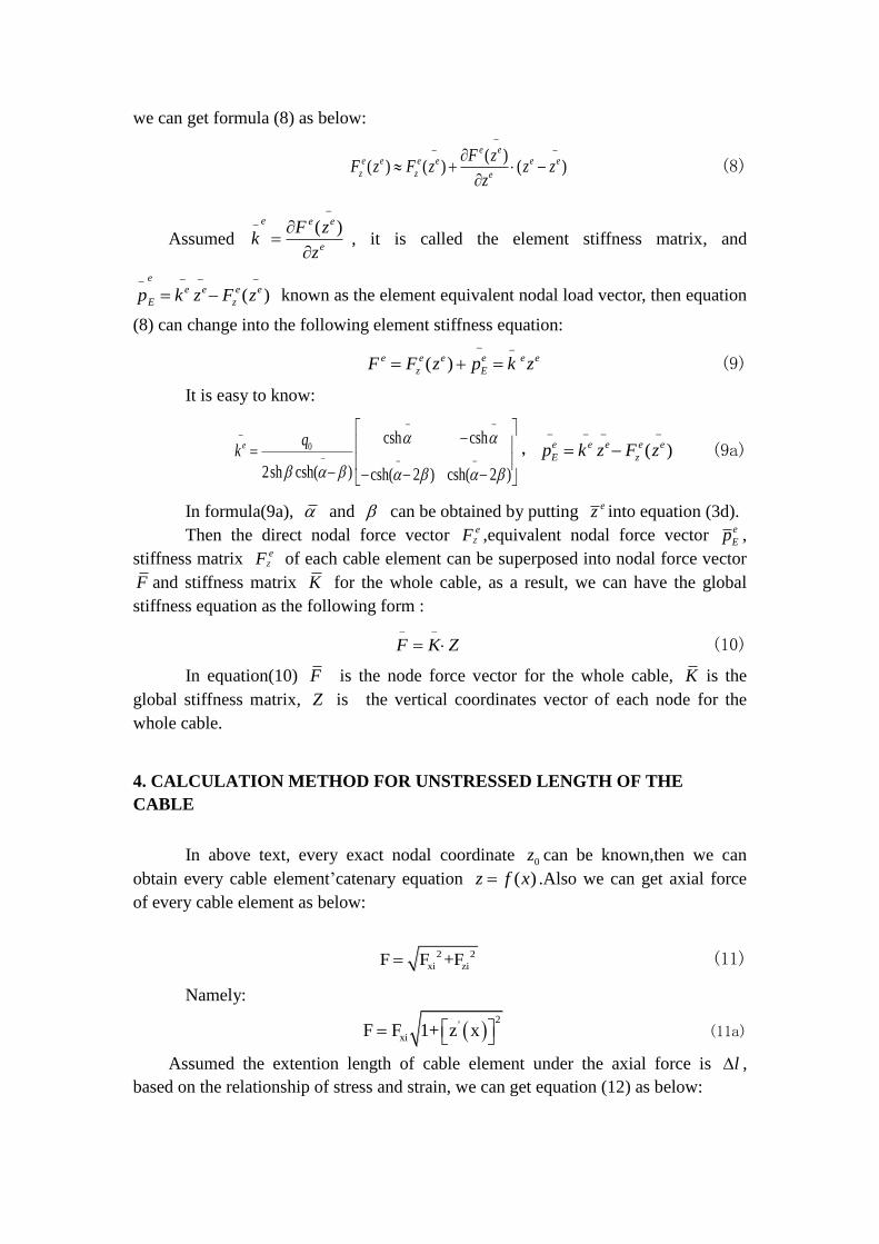
we can get formula (8) as below:
( )( ) ( ) ( )
e ee e e e e e
z z e
F zF z F z z z
z
(8)
Assumed ( )
e e e
e
F zk
z
, it is called the element stiffness matrix, and
( )e
e e e e
E zp k z F z
known as the element equivalent nodal load vector, then equation
(8) can change into the following element stiffness equation:
( )e e e e e e
z EF F z p k z
(9)
It is easy to know:
0csh csh
2sh csh( ) csh( 2 ) csh( 2 )
e qk
, ( )e e e e e
E zp k z F z
(9a)
In formula(9a), and can be obtained by putting ez into equation (3d).
Then the direct nodal force vector Z
eF ,equivalent nodal force vector e
Ep ,
stiffness matrix Z
eF of each cable element can be superposed into nodal force vector
F and stiffness matrix K for the whole cable, as a result, we can have the global
stiffness equation as the following form :
F K Z
(10)
In equation(10) F is the node force vector for the whole cable, K is the
global stiffness matrix, Z is the vertical coordinates vector of each node for the
whole cable.
4. CALCULATION METHOD FOR UNSTRESSED LENGTH OF THE
CABLE
In above text, every exact nodal coordinate 0z can be known,then we can
obtain every cable element’catenary equation ( )z f x .Also we can get axial force
of every cable element as below:
2 2
xi ziF F +F (11)
Namely:
2
'
xiF F 1+ z x (11a)
Assumed the extention length of cable element under the axial force is l ,
based on the relationship of stress and strain, we can get equation (12) as below:
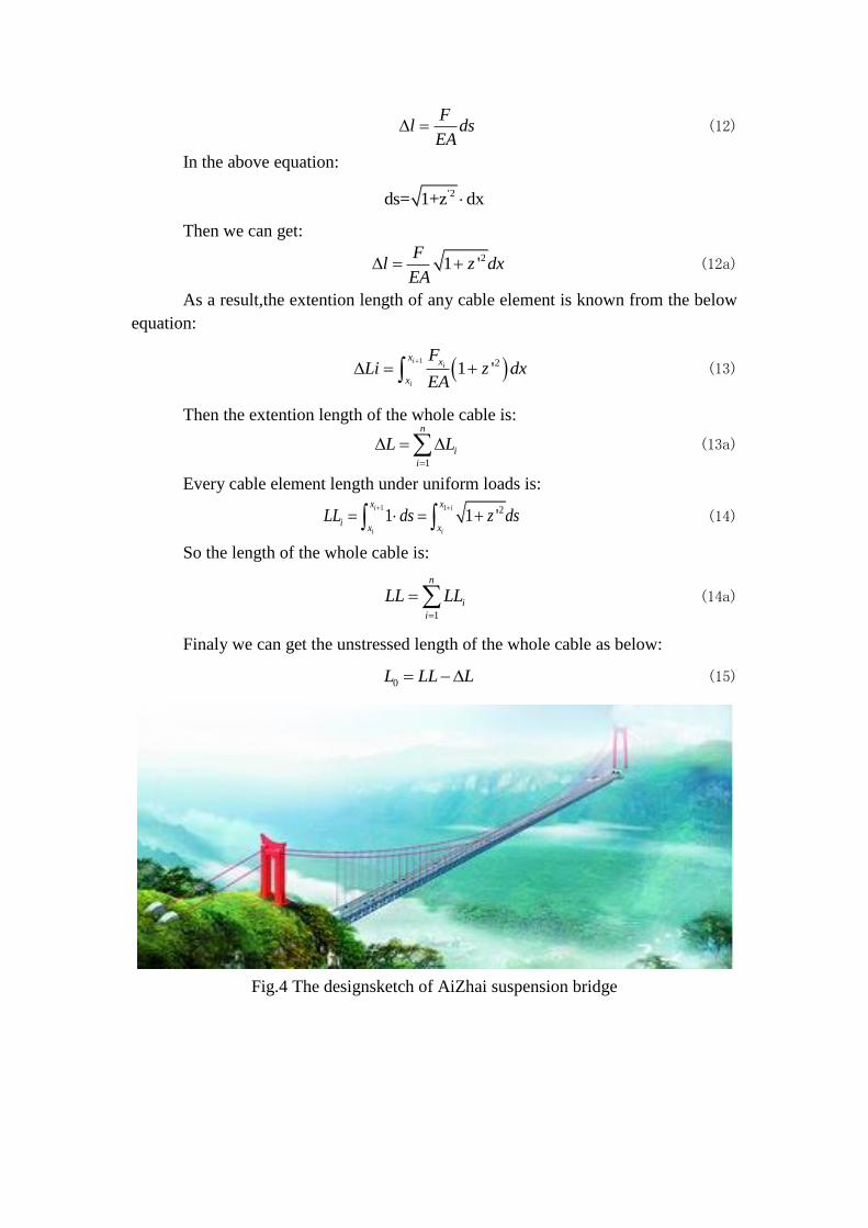
Fl ds
EA (12)
In the above equation:
'2ds= 1+z dx
Then we can get:
21 'F
l z dxEA
(12a)
As a result,the extention length of any cable element is known from the below
equation:
1 21 '
ii
i
x x
x
FLi z dx
EA
(13)
Then the extention length of the whole cable is:
1
n
i
i
L L
(13a)
Every cable element length under uniform loads is:
1 1 21 1 'i i
i i
x x
ix x
LL ds z ds
(14)
So the length of the whole cable is:
1
n
i
i
LL LL
(14a)
Finaly we can get the unstressed length of the whole cable as below:
0L LL L (15)
Fig.4 The designsketch of AiZhai suspension bridge

5. FLOW CHART OF CALCULATION PROCEDURE
In the process of practical calculation, firstly take vertical uniform loads on
element as 0zq q ,on the case, the shape of cable element is parabolic, so we can get
a group of nodal vertical coordinates as initial solution z ; then take2
0 1 ( ')zq q z ,and take z as a known initial value, so we can obtain a group of
new nodal vertical coordinates, which will be the new initial value for the next
calculation. Then, the liner of cable element will convergence from parabolic to
catenary step by step. When the convergence solution can fufill the precision asked
for, the calculation procedure can break, and we can get the exact vertical coordinates
of all nodes.
And then take the exact nodal vertical coordinates as known conditions, we
can get the curve equation of all cable elements. Finally we can obtain the original
length and extension length and unstressed length on basis of
equations(13),(14),(13a),(14a).detailed calculation flow chart as shown in figure 5.
Take 0zq q into equation ' '( ) 0zHz q ,get parabolic analytical solution ( )z x
Run equation (6a),get every elements’ek , e
EP
Integrate ek , e
EP into K ,F
Run equation (7),get initial nodal vertical coordinates vector 0z
Take 2
0 1 ( ')zq q z into equation ' '( ) 0zHz q ,get catenary solution ( )z x
Take every elements’ 0
ez
of 0z
as initial coordinates into
( )z x
Run equation (9a),get every element’se
Ep
,ek
Integrate all elements’e
Ep
and ek
into F
and
K
Run equation (10),get Z ,check solution fulfil the precision conditions
NO
Take 0z
= Z
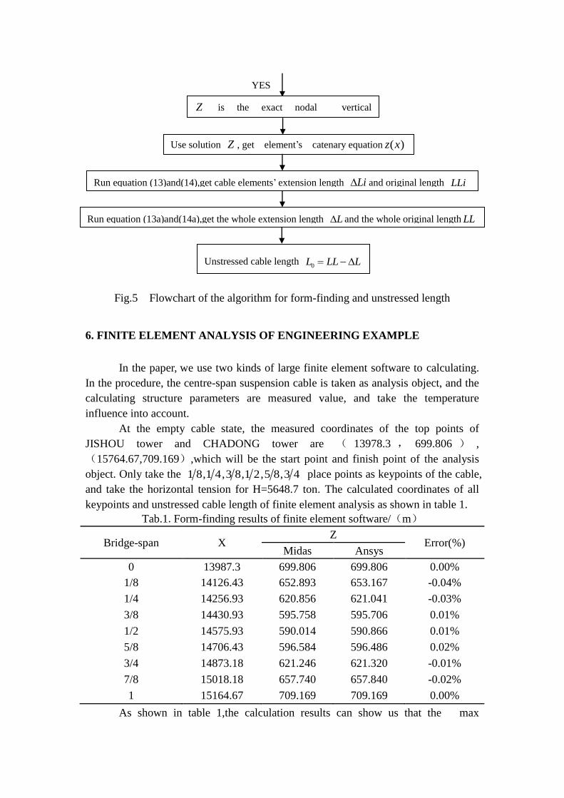
Fig.5 Flowchart of the algorithm for form-finding and unstressed length
6. FINITE ELEMENT ANALYSIS OF ENGINEERING EXAMPLE
In the paper, we use two kinds of large finite element software to calculating.
In the procedure, the centre-span suspension cable is taken as analysis object, and the
calculating structure parameters are measured value, and take the temperature
influence into account.
At the empty cable state, the measured coordinates of the top points of
JISHOU tower and CHADONG tower are ( 13978.3 , 699.806 ) ,
(15764.67,709.169),which will be the start point and finish point of the analysis
object. Only take the 1 8,1 4,3 8,1 2,5 8,3 4 place points as keypoints of the cable,
and take the horizontal tension for H=5648.7 ton. The calculated coordinates of all
keypoints and unstressed cable length of finite element analysis as shown in table 1.
Tab.1.Form-finding results of finite element software/(m)
Bridge-span X Z
Error(%) Midas Ansys
0 13987.3 699.806 699.806 0.00%
1/8 14126.43 652.893 653.167 -0.04%
1/4 14256.93 620.856 621.041 -0.03%
3/8 14430.93 595.758 595.706 0.01%
1/2 14575.93 590.014 590.866 0.01%
5/8 14706.43 596.584 596.486 0.02%
3/4 14873.18 621.246 621.320 -0.01%
7/8 15018.18 657.740 657.840 -0.02%
1 15164.67 709.169 709.169 0.00%
As shown in table 1,the calculation results can show us that the max
YES
Z is the exact nodal vertical
coordinates
Use solution Z , get element’s catenary equation ( )z x
Run equation (13)and(14),get cable elements’ extension length Li and original length LLi
Run equation (13a)and(14a),get the whole extension length L and the whole original length LL
Unstressed cable length 0L LL L

vertical coordinates error at the same horizontal coordinate is 0.04%, it can prove
results of the two kinds of finite element software are similar; and the max
unstressed cable length error between self-made program and finite element
software shown in table 2 is 0.006%,it prove the results are exact.
Tab.2.Results of unstressed cable length/(m)
Calculation
software
Oringinal
length
Extension
length Unstressed length
Error with
program
Midas civil 1206.579 0.759 1205.82 0.006%
Ansys 1206.553 0.743 1205.81 0.003%
Procedure 1206.511 0.707 1205.804 0.000%
7. COMPARISON BETWEEN THEORETICAL CALCULATION AND
MEASURED VALUE
According to the calculation theory for form-finding, make use of self-made
program to calculate the coordinates of keypoints, then compare the results with the
results of finite element software and measured value in table 3 and figure 6, the
value in table shows that the max error of self-made program and measured value is
0.012%, it proves the calculation theory exact, the results can fulfill the engineering
accuracy.
Tab.3 Form-finding results of Self-made program and measured value/(m)
Bridge-span X
Z
Error Theoretical calculation Measured value
0 13987.3 699.806 699.806 0.000%
1/8 14126.43 652.894 652.839 -0.008%
1/4 14256.93 620.858 620.896 0.006%
3/8 14430.93 595.761 595.711 -0.008%
1/2 14575.93 590.018 590.091 0.012%
5/8 14706.43 596.587 596.588 0.000%
3/4 14873.18 621.248 621.257 0.001%
7/8 15018.18 657.741 657.730 -0.002%
1 15164.67 709.169 709.169 0.000%

Fig.6 The results curve of finite softwares and self-edit program and measured results
8. CONCLUDING REMARKS
1. Compared to the Nonlinear Finite Element method, the method of precise
form finding for cable unit can reduce divided unit density and number of elements in
matrix calculation so as to improve the operation speed.
2. With the vertical load distribution changing from along the string length to
the arc length, cable units converge into accurate catenary by the nonlinear iteration
with the initial parabolic value which has been near exact solution. Therefore, the
method greatly accelerates the convergence speed.
3. The calculation method is put forward for cable-length in non-stress on the
premise that the precise coordinates of suspension cable have been achieved
according to theory of precise form-finding for cable element.
4. By taking Aizhai Suspension Bridge as an engineering example, the paper
has analyzed the measurements and the results of finite element software, and verifies
the accuracy of calculation theory and the self-made calculation program.
Acknowledgements
This paper cost many people’s time and energy. My deepest gratitude goes
first and foremost to my tutor, Professor Wang Ronghui, for his constant
encouragement and guidance. He has helped me a lot through all the stages of the
writing of this paper. Without his constant instruction, this paper can’t be managed to
reach this present form.
My sincere thanks goes to Wei Yuancheng and Huang Xiaofeng,they also
helps me a lot by providing me many useful reference books.
I also owe my thanks to my dear friends and fellow classmates, who have
done me a favor in helping me work out my problems during the difficult course of
580.000 585.000 590.000 595.000 600.000 605.000 610.000 615.000 620.000 625.000 630.000 635.000 640.000 645.000 650.000 655.000 660.000 665.000 670.000 675.000 680.000 685.000 690.000 695.000 700.000 705.000 710.000
13987.3 14126.43 14256.93 14430.93 14575.93 14706.43 14873.18 15018.18 15164.67
Results of Midas civil
Results of Ansys
Results of self-edit program
Measured results

the paper.
I would like to deeply thank the all various people who, during the several
months in which this endeavor lasted, provided me with useful and helpful assistance.
Without their care and consideration, this essay would likely not have finished.
9. REFERENCES
[1] SHEN Shi-zhao.XU Chong-bao. Suspension Cable Structure
Design[M],BEIJING:China Architecture and Building Press,1997
[2] XIANG Yang,SHEN Shi-zhao.Initial Form-finding Analysis of Cable
Structures[J]. Journal of Harbin University of Civil Engineering and
Architecture,1997,30(3):29-33.
[3] YAN Jing-tong,GAO ri.Comparison And Analysis Between Two Form-finding
Methods For Cable Net Structures[J].Steel Structure 2002,17(1):4-6.
[4] SCHEK H K.The force densities method for form-finding and computation of
general nets[J].Computer Methods in Applied Mechanics
Engineering,1974.3(1):115-134.
[5] BARNES M R.Dynamic relaxation analysis of tension networks[A].Proceedings
of the International Conference on Tension Structure[C].London,April,1974.
[6] Zhou meng-bo. Suspension bridge manual [M], Beijing:China Communications
Press, 2003.8.
[7] YUAN Si, CHENG Da-ye, YE Kang-sheng.. Exact Element Method for
Form-finding Analysis of Cable Structures [J].Journal of Building Structures
2005,26(2):46-51.
[8] Wang Xin-ming. ANSYS Engineering structure numerical analysis[M],
Beijing:China Communications Press, 2007.10.