application of fem simulation for the support of design...
TRANSCRIPT

XXVI Verformungskundliches Kolloquium Masek Behulova Mahn Meyer
Application of FEM simulation for the support of design and optimisation of forming processes
B Masek - M Behulova - U Mahn4 - L W Mcyer
I University of West Bohemia Univerzitni 22306 14 Plzen Czech Republic 2 TU Cherrmitz Fakultat fur Maschinenbau LWM Erfenschlager Str 73
D-09107 Cherrmitz Germany lotharmeyerwsktu-chemnitzde 3 Slovak University of Technology Faculty of Materials Science and Technology
Paulinska 16 917 24 Trnava Slovak Republic 4 Eska Sachsische Schraubenwerke GmbH Lutherstr 87 D-09l26 Chemnitz Germany
bohuslavmase kW)wsk tu-cherrmitz de maria beh ul0 vastubask umahneskanet
Abstract
The development of unconventional technologies often requires attainment of narrow tolerances of several technological parameters in order to assure the maximal efficiency of the process In many cases it is impossible to observe all complex phenomena occurring during manufacturing process Moreover the possibility of direct measurement of some physical and technological parameters is also limited In this reason it is necessary to explore and apply new methods for analysis and quantification of interrelated phenomena One of effective means in this area represents the application of FEM simulation accompanied by simplified experiments Using such procedure needed know-how for FEM simulation of more complex processes can be obtain In the paper some examples of FEM analyses used for design and development of new technology in the field of unconventional forming and thermomechanical treatment are introduced
1 Introduction
During thermo mechanical treatment (TMT) of materials appropriate relations between deformation and temperature fields are essentially required for attainment of microstructures generally with better material properties than structures achieved by conventional treatment Furthermore thermomechanical treatment enables considerable energy saving for heating and heat treatment when suitable process arrangement is used Additionally total operation time can be reduced as well For example in the technology of rotary spin extrusion sequential and partial heating of semi-product can be exploited to influence the microstructure development during and after incremental deformation process However this requires to ensure not only desired temperature distribution in treated semi-product before forming but also to control the temperature fields in handled product over time during whole TMT On the other hand suggested methods of heating lead to more effective energy utilization and improving of surface quality of formed semi-product due to the reduction in scaling and decarburisation of undersurface layer For the development of the process of rotary spin extrusion including technological equipment a detail analysis of possibilities of temperature field generation and influencing in handled semi-product was performed using FEM simulation
171
XXVI Verformungskundliches Kolloquium Masek Behulova Mahn Meyer
2 Technology of rotary spin extrusion
Technology of rotary spin extrusion developed at the Chemnitz University of Teclmology is dedicated to the manufacturing of hollow shaft s for vehicle gear boxes [1-5] This technology takes advantage of a very efficient incremental forming process Applying unique incremental-deformation method with roll-off tools enables production of hollow and internally profiled parts directly from cylindrical rod semi-products with minimal material losses usually connected with conventional machining such as drilling or turning The principle of rotary spin extrusion is based on the deformation effect of three rollers located on the diameter of the forming zone that form the outer shaft contour (Fig 1) At the same time the spike is pressed in the axial direction into the rod to form the inner shaft contour Thu s the material displaced by rollers and the forming spike runs off axially forming a cup wall The rotational movements of the spike and rollers are not generated by separate driving mechanisms but they result from the friction Because the spike is rotating with the same angular velocity as the formed rod semi-product it is possible to produce even incircular or profiled inner shapes such as polygons internal toothing multiple-spline profiles using accordingly designed forming spikes (Fig 2) In only one formin g step the semishyfinished hollow shafts with a 1ength-diameter ratio up to 20 can be produced [6]
Fig 1 Scheme of the technology of rotary spin extrusion [1 7]
Fig 2 Hollow and internally profiled shafts manufactured by rotary spin extrusion [7]
Depending on the material of the formed semi-product and required accuracy of internal and external shapes the rotary spin extrusion can be used as a cold- warm- or hot- forming technique The high-strength steels are supposed to be treated by increased temperatures in order to improve conditions for plastic material flow what results in considerable reduction of the punch power [2 5] Moreover the exploitation of incremental deformations at higher temperatures exhibits positive consequences on the microstructure and the material properties particularly on the ductility ultimate and impact strength In this reason wide range of strategies of thermo-mechanical treatment of steels has been examined and verified experimentally for the technolo gy of spin extrusion [8-13] In this work the possibilities of the use ofFEM simulation to study analyse and optimise the process chain of hollow shaft production are illustrated through chosen examples In all cases the formed material is the low-alloyed relatively cheep 20MoCrS4 steel which is at present widely exploited in the automotive industry for rotary parts
172
XXVI Veriormungskundliches Kolloquium Masek Behulova Mahn Meyer
water jet cooling
inductor
air cooling
rollers
inductor
water cooling
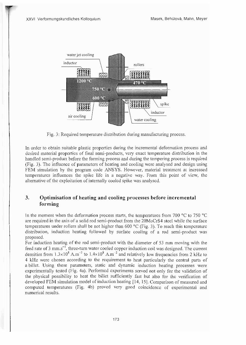
Fig 3 Required temperature distribution during manufacturing process
In order to obtain suitable plastic properties during the incremental deformation process and desired material properties of final semi-products very exact temperature distribution in the handled semi-product before the forming process and during the tempering process is required (Fig 3) The influence of parameters of heating and cooling were analysed and design using FEM simulation by the program code ANSYS However material treatment at increased temperatures influences the spike life in a negative way From this point of view the alternative of the exploitation of internally cooled spike was analysed
3 Optimisation of heating and cooling processes before incremental forming
In the moment when the deformation process starts the temperatures from 700degC to 750 degC are required in the axis of a solid rod semi-product from the 20MoCrS4 steel while the surface temperatures under rollers sha ll be not higher than 600degC (Fig 3) To reach this temperature distribution induction heating followed by surface cooling of a rod semi-product wa s proposed For induction heating of the rod semi-product with the diameter of 53 mm moving with the feed rate of 3 mm s-) three-turn water cooled copper induction coil was de signed The current
2densities from 13x 108 Am- to 14xl08 Am-2 and relatively low frequencies from 2 kHz to 4 kHz were chosen according to the requirement to heat particularly the central parts of a billet Using the se parameters static and dynamic induction heating processes were experimentally tested (Fig 4a) Performed experiments served not only for the validation of the phy sical possibility to heat the billet sufficiently fa st but also for the verification of developed FEM simulation model of induction heating [14 15] Comparison of measured and computed temperatures (Fig 4b) proved very good coincidence of experimental and numerical results
173
XXVI Verformungskundliches Kolloquium Masek Behulova Mahn Meyer
Thermocouple I cal 2 cal 3 cal 4 cal 5 cal 6 cal I_exp 2_exp 3_exp 4_exp 5_exp 6_exp
200
15 30 45 60 75 90 105 120
800-------shy - - --------------shy - - ----
700
IT 600 e (]) 500 2e 400 (])
0 E 300 (])
f-lt
b) Time [s]
Fig 4 Experimental temperature measurement by induction heating (a) and comparison of measured temperatures (dashed lines) and computed temperatures (solid lines)
using the coupled electro-magnetic and thermal FEM analysis (b)
31 Analysis and optimisation of cooling process
The surface cooling was initiaJJy computer tested using pressure air It was found that the application of technically the most simple air cooling is not intensive enough for quenching the rod surface to the required temperature under rollers [16 17] In the next step it was supposed that the rod semi-product is cooled after the induction heating at first by water spraying and then subcooled by air free convection and radiation This combination of cooling media in a described sequence resulted in rapid fall of surface temperatures during water spray cooling and to their following slight increase during air cooling [16 17] Moreover the heat generated in a billet due to the induction heating was not used effectively According to the basic principles of induction heating approximately 87 of generated Joule heat is concentrated owing to the skin effect in the surface area of a heated billet The heat transfer to the central parts of the billet is realised by the mechanisms of conduction for which some time is needed In case of water jet cooling location immediately behind the inductor the surface layers are quenched before the heat has chance of being transferred to the rod center In above mentioned reasons the exchange of cooling zones was finally suggested The lengths of cooling zones and intensity of water spray cooling were optimised in order to attain required temperature field in a heated billet before the forming process For the considered feed rate of 3 mms -I the length of air cooling zone (Fig 3) was changed from 10 mm to 30 mm supposing the water spray cooling with the mass flow from 460 kgmfrnin to 1000 kgm - 2min-1 According to Jeshar [18] corresponding average heat transfer coefficients are approximately from 1000 Wm-2K-1 to 2000 Wm-2K- 1
bull The current density in inductor coil was set to the constant value of 135x 108 Am-2 by the frequency of2 kHz As it follows from the time histories in the node 1 in the billet axis and in the node 2 at the billet surface (Fig 5) the shorter air cooling zones are not advantageous as the water cooling
174
XXVI Verformungskundliches Kollcquiurn Masek Behulova Mahn Meyer
b [null] -shy 10 - _-_ 15 - shy 20
25 275 30
starts before attainment of the maximum temperature in the node 2 at the billet surface The elongation of air cooling zone results in the temperature increase in the billet axis due to the heat conduction from the billet surface to its central parts Temperatures in the node I at the beginning of the forming process attain the values from 700 C to 750 C except the case with air cooling zone length of 10mm when the axial temperature is lower than required However the length of water cooling zone reduced by extension of air cooling zone may not be sufficient to assure the quenching of a bi11 et surface in the area of the node 2 under 600 dege
1000 800 h 0= 1200 Wm-2 K-l
900 750 I-- - middot 750 dege -- ------- ------- ----- --shy800 ~~_~~~~U 700U =-----o7002 --- 650
ltUQ) 600 600 0e ~T---2 2 600 ~--_ __ _-~-~~~
~ Q)e 500 0shy 8 550 ~--------shyE 400 EltLl f- ~ 500 ~----300 ------shy
~450200 --- NODE h [Wm-2K-J
- - I -T-[OOO --1500 --2 - -1200 --2000
0
400100
350 0 3 6 9 12 15 18 21 24 27 10 15 20 25 30
Time [5] Air cooling zone length [rnrn]
Fig 5 Temperature histories in the node 1 Fig 6 Dependence of temperatures in the (dashed lines) and in the node 2 (solid lines) nodes I (red) and 2 (black) at the end of cooling for different lengths of air cooling zones b process illustrating the influence of intensity and water mass flow of 570 kgm-2min-1
bull of water spray cooling
Intensity of water spray cooling given by varied heat transfer coefficient for different water mass flow influences more surface temperatures than axis temperatures (Fig 6) To reach the minimal required axial temperature of 700degC the air cooling length should be about 18 mm at minimum The influence of intensity of water jet cooling on the axis temperature at the end of cooling is not relevant for the air cooling zones with the length more than 25 mm In this reason the air cooling zone with the length from 25 mm to 27 mm and corresponding water spray cooling zone length from 35 min to 33 mm can be considered as optimal For these lengths of cooling zones the water mass flow from 570 kgmfmin (h = 1200 Wm-2K-1
) to 730 kgmimin (h = 1500 Wm~2K~I) can be recommended according to the surface temperatures at the end of cooling The lower water mass flows are not sufficient for required surface quenching On the other hand surface temperatures are too low when more intensive water cooling is applied
32 Optimisation of induction heating process
The next task concerned the optimising of inductor power and necessary current density in induction coil respectively Using the frequency of 2 kHz and optimised parameters of cooling (air cooling zone with the length of 25 mm the water cooling zone length of 3S mm
175
Masek Behulova Mahn MeyerXXVI Verformungskundliches Kolloquium
with the water jet mass flow from 570 kgm-2min- 1 to 730 kgmfrnin) the influence of current density in induction coil on the axis and surface temperatures in the nodes 1 and 2 was analysed (Figs 7 - 8) The increase in intensity of water cooling affects particularly billet surface temperatures The needed current density to reach the axis temperatures from 700 C to 750 0 e attains values from approximately 131xl08 Am-2 to 137xl08 Am-2
bull For these current densities in induction coil and considered cooling conditions the surface temperatures in the node 2 are as required below 600 C Moreover the maximum temperatures during the heating process are lower than allowed temperature of 1200 C The computed temperature distribution in the rod semi-product just before the starting of incremental forming process (Fig 9) satisfies required conditions for thermomechanical treatment
10001200 -f- h= 1200 Wrn-2K-1
1150 900 -e- h=ISOO~1100 800
U 1050 U 2 2 700
1000 r-v
~~-~-
~- T 1
v -~-= 600 - aE 750 e laquol 500v
g 700 a E 400 13 Am-z
sect 650 v f shy f shy 133 Am-z
300--
600 135 Am- 2
200550 137 Am-2
500 roo Am-z - - T - - T 14 2 max 450 0
1301 321341 361 38140 0 3 6 9 12 IS 18 21 24 27
Current density j J 0 -8 [Am-2] Time [s]
Fig 7 Dependence of the axial temperature Fig 8 Time history of the axial temperature and surface temperature at the end of cooling (NODE 1) and surface temperature (NODE 1) and the maximum temperature during heating at the billet head for chosen current densities process on the current density in inductor coil in inductor coil
20 135 250 364 468 592 707 821 936 1050
Fig 9 Temperature distribution in a rod semi-product (a detail) before the forming process computed using the designed parameters of induction heating and cooling
176
XXVI Verformung skundliche s Kolloquium Masek Behulova Mahn Meyer
4 Analysis of induction tempering process
In order to achieve required mechanical and utility properties of hollow sha fts produced by the technology of rotary spin extrus ion the tempering procedure is supposed to be integrated to the process chain during thennomechanical treatment of material [12J This proc edure involves material cooling from the temperature of 750degC reached in the zone of intensive deformations in the front of spike (Fig 3) to the temp erature approximately 470 degC in the zone afte r the forming rollers followed by the holding time at this temperature using induction heating The main aim of the performed numerical analysis wa s to design parameters of water cooling and induction heating including the intensity of water spray cooling geo metry of induction coil frequenc y and needful inductor power The influence of induction heating on the spik e temperatures was evaluated as well Based on the obtained result s of numerical simulation of cooling and induction heat treatment the following parameters are recommended for the uniform shaft heating to the required holding temperature (Fig 10) bull spray cooling with the water mass flow of 450 kgrnimin in the zone with the length of
60 mm followed by air cooling before induction heating bull inductor shape 12-tum copp er water cooled induction coil with the total length of 164 nun bull frequ ency 4000 Hz bull current density in the induction coil given by the time dependent function with the
maximum of j = 3x10⁷ Am- 2 at the beginning of induction heating
680 rr------------------------
640
2 600 ltU
~ 560 sectamp520 E ~ 480
440 water air
cooling icooling j induction heating
030 025 005 400 L----l_-----~----_-----_____L______L_ ____ ______ _ __________________---J
000 010 015 020
Distance from roIlers x [m]
Fig 10 Temp erature distribution along the outer shaft surface in the time of 30 sec
5 Analysis of temperature distribution in the internally cooled spike
At pre sent a solid spike is used for hollow shaft manu facturing by rotary spin extrusion During the process of thennome chanica1 treatment and particularly during the holding time the spike is expo sed to increased temperatures what can finally result in loss of spike life In thi s reason the possibility of the use of internally cooled spike was analysed Several variants of geometrically different cooling systems were considered The diameter of a hole in the spike D for the cooling water supply was suppose d to be from 6 mm to 20 mm (Fig lla)
177
XXVI Verformungskundliches Kolloquium Masek Behulova Mahn Meyer
Based on performed static and buckling analyses the spike with a hole of 16 mm in diameter was recommended for placement of cooling system Hence the internal diameter of the cooling pipe d was supposed to be from 5 mm to 9 mm whereas the pipe wall thickness 0 was modeled from 15 mm to 2 mm The dependence of the maximum temperature of cooling water on the internal diameter of water feed pipe (Fig l lb) revealed that the pipe with internal diameter of7 mm and the wall thickness of 2 mm is optimal from the point of view of water cooling temperature This geometry of cooling system is also suitable considering the maximum spike temperature
530--------------------- 120
-e- spike temperature water feed pipe o~ - T- water temperature
ltl) 528 cooling water 3 amp 526 E B Q)
5 524 E J
x E 522 ro ~
D 5 678 9 Internal diameter d [mm]
Fig 11 Main geometrical characteristics of cooling system (a) and their influence on the maximum water and spike temperatures (b)
520 ---_~_l-_~_---_~_L__~----- 70
350 405235 295 18012565
y [ms] bull__II==~~~~=l~==~JI_1lIIlIIII
0 065 0135 0202 0270 0338 OA05 OA73 s
_- ~-- ~ ~~ ~~-~ C---shy ----- ~ - -oolIIliIiIIiiiI
I l ~
c
Fig 12 Computed velocities (upper part - A) and temperatures (bottom part - B) in cooling system and spike for recommended geometrical parameters of internally cooled spike
with a detail in part C
The highest temperatures above 500 degC are reached locally at the tip of a spike (Fig 12) However the temperatures at the surface of conical part of a spike do not exceed the allowable value of 400degC As it follows from the velocity distribution in Fig s 12A and l2C the optimisation of the hole frontal part is advisable in order to improve the water flow around the inside frontal wall of the spike Finally such modification can assure more intensive cooling of the sp ike tip
178
XXVI Verformungskundliches Kolloquium Masek Behulova Mahn Meyer
6 Conclusions Numerical simulation of technological processes enables to analyse investigated phenomena in mutual relationships and causalities and to optimise parameters of the process from many aspects The main problem in the field of application of numerical simulation for complex comprehensive technological processes consist s today particularly in input parameters i e definition of material properties and material behavior setting of reliable nonlinear and mostly also time dependent boundary conditions and loading From this point of view the verification of chosen numerical results by experimental mea surements is unavoidable However the computer simulation represents a very efficient and powerful tool for design and optimisation of advanced unconventional technological processes
Acknowledgements
The research has been supported by VEGA MS SR and SAV within the project No 1207305 and the Research Centre of Forming Technology FORTECH
References
[1] R Glass F Hahn M Kolbe and LW Meyer Processes of partial bulk metal-forming - aspects of technology and FEM simulation Journal of Materials Processing Technology Vol 80-81 1998pp 174-178
[2] R Neugebauer M Kolbe and R Glass New warm forming processes to product hollow shafts Journal of Materials Processing Technology Vol 1192001 pp 277-282
[3] R Neugebauer M Kolbe and R Glass New process chains to fabricate hollow shafts by partial forming Production Engineer ing Research and Development Vol 8 Book 22001 pp 29-34
[4] R Neugebauer U Mahn und D Weidlich Berucksichtigung von Ma schinenelementen in komplexen FE-Modellen Konstruktion Vol 92001 pp 55-58
[5] R Neugebauer R Glass M Kolbe and M Hoffmann Optimisation of processing routes for cross rolling and spin extrusion Journal of Materials Processing Technology 2002 pp 856-862
[6] R Michel R Kreif3ig and H Ansorge Thermomechanical finite element analysis (FEA) of spin extrusion Forschung im Ingenieurwesen 68 2003 pp 19-24
[7] http tZwwwiwu fraunhoferde [online] [cit 2006-04-15 1008 SEC] [8] B Ma sek L W Meyer and Z Novy Improving of Mechanical Properties of
38MnSiVS5 Steel by Multiple Deformation In International Conference PEDD 6 Egypt Cairo Ain Shams University 2002
[9] L W Meyer und B Masek Eigenschaftsopti-mierung durch gezielte TMB integriert in eine Masiv-umformprozesskette In 8th Saxon Conference of Forming Technology TU- BA Freiberg 2001 pp 176-186
[10] D Jandova L W Meyer B Masek Z Novy D Kesner and 1 Motycka The influence of thermo-mechanical processing on the microstructure of steel 20MoCrS4 Materials Science and Engineering A349 2003 pp 36 -47
179
XXVI Verformungskundliches Kolloquium Masek Behulova Mahn Meyer
[11] D Jandova J Rehor and Z Novy Microstructural changes taking place during the thermo-mechanical processing and cold working of steel 18Cr18MnO5N Journal of Materials Processin g Technology Vol 157-158 2004 pp 523-530
[12] B Masek R Neugebauer U Mahn and L W Mey er Integration of a Thermoshymechanical Treatment in to the Spin Extrus ion Process Stahl und Eisen 124 No9 2004 pp 77-82
[13] H Stafikova B Masek and L W Meyer The Influence of the Incremental Deformation Intensity on the Microstructure Development In 7th International Conference on Production Engineering and De sign for Development PEDD 2006 Cairo Egypt
[14] M Behulova Simulation model of induction heating for the process of rotary spin extrusion Research Papers MtF STU Trnava Vol 152003 pp 9-18
[15] M Behulova B Masek and L W Meyer Static and dynamic induction heating shyexperiment and numerical simulation MP-Materialprtifung Vol 48 No5 2006 pp 217-224
[16] M Behulova B Masek and L W Meyer Virtual testing of the dynamic induction heating Finite elements in Analysis and De sign (to be published)
[17] M Behulova Simulation model of induction heating for the process of rotary spin extrusion Research Papers MtF STU Tmava Vol 172004 pp 9-15
[18] R Jeschar V Specht und V Heidt Mechanismen der Warmeubertragung Bei Kuhlen von Metallen mit verdamfenden Flussigkeiten Braunschweigischen Wissenschaftlichen Geselschaft Verlag Erich Goltze Gottingen 1991
180

XXVI Verformungskundliches Kolloquium Masek Behulova Mahn Meyer
2 Technology of rotary spin extrusion
Technology of rotary spin extrusion developed at the Chemnitz University of Teclmology is dedicated to the manufacturing of hollow shaft s for vehicle gear boxes [1-5] This technology takes advantage of a very efficient incremental forming process Applying unique incremental-deformation method with roll-off tools enables production of hollow and internally profiled parts directly from cylindrical rod semi-products with minimal material losses usually connected with conventional machining such as drilling or turning The principle of rotary spin extrusion is based on the deformation effect of three rollers located on the diameter of the forming zone that form the outer shaft contour (Fig 1) At the same time the spike is pressed in the axial direction into the rod to form the inner shaft contour Thu s the material displaced by rollers and the forming spike runs off axially forming a cup wall The rotational movements of the spike and rollers are not generated by separate driving mechanisms but they result from the friction Because the spike is rotating with the same angular velocity as the formed rod semi-product it is possible to produce even incircular or profiled inner shapes such as polygons internal toothing multiple-spline profiles using accordingly designed forming spikes (Fig 2) In only one formin g step the semishyfinished hollow shafts with a 1ength-diameter ratio up to 20 can be produced [6]
Fig 1 Scheme of the technology of rotary spin extrusion [1 7]
Fig 2 Hollow and internally profiled shafts manufactured by rotary spin extrusion [7]
Depending on the material of the formed semi-product and required accuracy of internal and external shapes the rotary spin extrusion can be used as a cold- warm- or hot- forming technique The high-strength steels are supposed to be treated by increased temperatures in order to improve conditions for plastic material flow what results in considerable reduction of the punch power [2 5] Moreover the exploitation of incremental deformations at higher temperatures exhibits positive consequences on the microstructure and the material properties particularly on the ductility ultimate and impact strength In this reason wide range of strategies of thermo-mechanical treatment of steels has been examined and verified experimentally for the technolo gy of spin extrusion [8-13] In this work the possibilities of the use ofFEM simulation to study analyse and optimise the process chain of hollow shaft production are illustrated through chosen examples In all cases the formed material is the low-alloyed relatively cheep 20MoCrS4 steel which is at present widely exploited in the automotive industry for rotary parts
172
XXVI Veriormungskundliches Kolloquium Masek Behulova Mahn Meyer
water jet cooling
inductor
air cooling
rollers
inductor
water cooling
Fig 3 Required temperature distribution during manufacturing process
In order to obtain suitable plastic properties during the incremental deformation process and desired material properties of final semi-products very exact temperature distribution in the handled semi-product before the forming process and during the tempering process is required (Fig 3) The influence of parameters of heating and cooling were analysed and design using FEM simulation by the program code ANSYS However material treatment at increased temperatures influences the spike life in a negative way From this point of view the alternative of the exploitation of internally cooled spike was analysed
3 Optimisation of heating and cooling processes before incremental forming
In the moment when the deformation process starts the temperatures from 700degC to 750 degC are required in the axis of a solid rod semi-product from the 20MoCrS4 steel while the surface temperatures under rollers sha ll be not higher than 600degC (Fig 3) To reach this temperature distribution induction heating followed by surface cooling of a rod semi-product wa s proposed For induction heating of the rod semi-product with the diameter of 53 mm moving with the feed rate of 3 mm s-) three-turn water cooled copper induction coil was de signed The current
2densities from 13x 108 Am- to 14xl08 Am-2 and relatively low frequencies from 2 kHz to 4 kHz were chosen according to the requirement to heat particularly the central parts of a billet Using the se parameters static and dynamic induction heating processes were experimentally tested (Fig 4a) Performed experiments served not only for the validation of the phy sical possibility to heat the billet sufficiently fa st but also for the verification of developed FEM simulation model of induction heating [14 15] Comparison of measured and computed temperatures (Fig 4b) proved very good coincidence of experimental and numerical results
173
XXVI Verformungskundliches Kolloquium Masek Behulova Mahn Meyer
Thermocouple I cal 2 cal 3 cal 4 cal 5 cal 6 cal I_exp 2_exp 3_exp 4_exp 5_exp 6_exp
200
15 30 45 60 75 90 105 120
800-------shy - - --------------shy - - ----
700
IT 600 e (]) 500 2e 400 (])
0 E 300 (])
f-lt
b) Time [s]
Fig 4 Experimental temperature measurement by induction heating (a) and comparison of measured temperatures (dashed lines) and computed temperatures (solid lines)
using the coupled electro-magnetic and thermal FEM analysis (b)
31 Analysis and optimisation of cooling process
The surface cooling was initiaJJy computer tested using pressure air It was found that the application of technically the most simple air cooling is not intensive enough for quenching the rod surface to the required temperature under rollers [16 17] In the next step it was supposed that the rod semi-product is cooled after the induction heating at first by water spraying and then subcooled by air free convection and radiation This combination of cooling media in a described sequence resulted in rapid fall of surface temperatures during water spray cooling and to their following slight increase during air cooling [16 17] Moreover the heat generated in a billet due to the induction heating was not used effectively According to the basic principles of induction heating approximately 87 of generated Joule heat is concentrated owing to the skin effect in the surface area of a heated billet The heat transfer to the central parts of the billet is realised by the mechanisms of conduction for which some time is needed In case of water jet cooling location immediately behind the inductor the surface layers are quenched before the heat has chance of being transferred to the rod center In above mentioned reasons the exchange of cooling zones was finally suggested The lengths of cooling zones and intensity of water spray cooling were optimised in order to attain required temperature field in a heated billet before the forming process For the considered feed rate of 3 mms -I the length of air cooling zone (Fig 3) was changed from 10 mm to 30 mm supposing the water spray cooling with the mass flow from 460 kgmfrnin to 1000 kgm - 2min-1 According to Jeshar [18] corresponding average heat transfer coefficients are approximately from 1000 Wm-2K-1 to 2000 Wm-2K- 1
bull The current density in inductor coil was set to the constant value of 135x 108 Am-2 by the frequency of2 kHz As it follows from the time histories in the node 1 in the billet axis and in the node 2 at the billet surface (Fig 5) the shorter air cooling zones are not advantageous as the water cooling
174
XXVI Verformungskundliches Kollcquiurn Masek Behulova Mahn Meyer
b [null] -shy 10 - _-_ 15 - shy 20
25 275 30
starts before attainment of the maximum temperature in the node 2 at the billet surface The elongation of air cooling zone results in the temperature increase in the billet axis due to the heat conduction from the billet surface to its central parts Temperatures in the node I at the beginning of the forming process attain the values from 700 C to 750 C except the case with air cooling zone length of 10mm when the axial temperature is lower than required However the length of water cooling zone reduced by extension of air cooling zone may not be sufficient to assure the quenching of a bi11 et surface in the area of the node 2 under 600 dege
1000 800 h 0= 1200 Wm-2 K-l
900 750 I-- - middot 750 dege -- ------- ------- ----- --shy800 ~~_~~~~U 700U =-----o7002 --- 650
ltUQ) 600 600 0e ~T---2 2 600 ~--_ __ _-~-~~~
~ Q)e 500 0shy 8 550 ~--------shyE 400 EltLl f- ~ 500 ~----300 ------shy
~450200 --- NODE h [Wm-2K-J
- - I -T-[OOO --1500 --2 - -1200 --2000
0
400100
350 0 3 6 9 12 15 18 21 24 27 10 15 20 25 30
Time [5] Air cooling zone length [rnrn]
Fig 5 Temperature histories in the node 1 Fig 6 Dependence of temperatures in the (dashed lines) and in the node 2 (solid lines) nodes I (red) and 2 (black) at the end of cooling for different lengths of air cooling zones b process illustrating the influence of intensity and water mass flow of 570 kgm-2min-1
bull of water spray cooling
Intensity of water spray cooling given by varied heat transfer coefficient for different water mass flow influences more surface temperatures than axis temperatures (Fig 6) To reach the minimal required axial temperature of 700degC the air cooling length should be about 18 mm at minimum The influence of intensity of water jet cooling on the axis temperature at the end of cooling is not relevant for the air cooling zones with the length more than 25 mm In this reason the air cooling zone with the length from 25 mm to 27 mm and corresponding water spray cooling zone length from 35 min to 33 mm can be considered as optimal For these lengths of cooling zones the water mass flow from 570 kgmfmin (h = 1200 Wm-2K-1
) to 730 kgmimin (h = 1500 Wm~2K~I) can be recommended according to the surface temperatures at the end of cooling The lower water mass flows are not sufficient for required surface quenching On the other hand surface temperatures are too low when more intensive water cooling is applied
32 Optimisation of induction heating process
The next task concerned the optimising of inductor power and necessary current density in induction coil respectively Using the frequency of 2 kHz and optimised parameters of cooling (air cooling zone with the length of 25 mm the water cooling zone length of 3S mm
175
Masek Behulova Mahn MeyerXXVI Verformungskundliches Kolloquium
with the water jet mass flow from 570 kgm-2min- 1 to 730 kgmfrnin) the influence of current density in induction coil on the axis and surface temperatures in the nodes 1 and 2 was analysed (Figs 7 - 8) The increase in intensity of water cooling affects particularly billet surface temperatures The needed current density to reach the axis temperatures from 700 C to 750 0 e attains values from approximately 131xl08 Am-2 to 137xl08 Am-2
bull For these current densities in induction coil and considered cooling conditions the surface temperatures in the node 2 are as required below 600 C Moreover the maximum temperatures during the heating process are lower than allowed temperature of 1200 C The computed temperature distribution in the rod semi-product just before the starting of incremental forming process (Fig 9) satisfies required conditions for thermomechanical treatment
10001200 -f- h= 1200 Wrn-2K-1
1150 900 -e- h=ISOO~1100 800
U 1050 U 2 2 700
1000 r-v
~~-~-
~- T 1
v -~-= 600 - aE 750 e laquol 500v
g 700 a E 400 13 Am-z
sect 650 v f shy f shy 133 Am-z
300--
600 135 Am- 2
200550 137 Am-2
500 roo Am-z - - T - - T 14 2 max 450 0
1301 321341 361 38140 0 3 6 9 12 IS 18 21 24 27
Current density j J 0 -8 [Am-2] Time [s]
Fig 7 Dependence of the axial temperature Fig 8 Time history of the axial temperature and surface temperature at the end of cooling (NODE 1) and surface temperature (NODE 1) and the maximum temperature during heating at the billet head for chosen current densities process on the current density in inductor coil in inductor coil
20 135 250 364 468 592 707 821 936 1050
Fig 9 Temperature distribution in a rod semi-product (a detail) before the forming process computed using the designed parameters of induction heating and cooling
176
XXVI Verformung skundliche s Kolloquium Masek Behulova Mahn Meyer
4 Analysis of induction tempering process
In order to achieve required mechanical and utility properties of hollow sha fts produced by the technology of rotary spin extrus ion the tempering procedure is supposed to be integrated to the process chain during thennomechanical treatment of material [12J This proc edure involves material cooling from the temperature of 750degC reached in the zone of intensive deformations in the front of spike (Fig 3) to the temp erature approximately 470 degC in the zone afte r the forming rollers followed by the holding time at this temperature using induction heating The main aim of the performed numerical analysis wa s to design parameters of water cooling and induction heating including the intensity of water spray cooling geo metry of induction coil frequenc y and needful inductor power The influence of induction heating on the spik e temperatures was evaluated as well Based on the obtained result s of numerical simulation of cooling and induction heat treatment the following parameters are recommended for the uniform shaft heating to the required holding temperature (Fig 10) bull spray cooling with the water mass flow of 450 kgrnimin in the zone with the length of
60 mm followed by air cooling before induction heating bull inductor shape 12-tum copp er water cooled induction coil with the total length of 164 nun bull frequ ency 4000 Hz bull current density in the induction coil given by the time dependent function with the
maximum of j = 3x10⁷ Am- 2 at the beginning of induction heating
680 rr------------------------
640
2 600 ltU
~ 560 sectamp520 E ~ 480
440 water air
cooling icooling j induction heating
030 025 005 400 L----l_-----~----_-----_____L______L_ ____ ______ _ __________________---J
000 010 015 020
Distance from roIlers x [m]
Fig 10 Temp erature distribution along the outer shaft surface in the time of 30 sec
5 Analysis of temperature distribution in the internally cooled spike
At pre sent a solid spike is used for hollow shaft manu facturing by rotary spin extrusion During the process of thennome chanica1 treatment and particularly during the holding time the spike is expo sed to increased temperatures what can finally result in loss of spike life In thi s reason the possibility of the use of internally cooled spike was analysed Several variants of geometrically different cooling systems were considered The diameter of a hole in the spike D for the cooling water supply was suppose d to be from 6 mm to 20 mm (Fig lla)
177
XXVI Verformungskundliches Kolloquium Masek Behulova Mahn Meyer
Based on performed static and buckling analyses the spike with a hole of 16 mm in diameter was recommended for placement of cooling system Hence the internal diameter of the cooling pipe d was supposed to be from 5 mm to 9 mm whereas the pipe wall thickness 0 was modeled from 15 mm to 2 mm The dependence of the maximum temperature of cooling water on the internal diameter of water feed pipe (Fig l lb) revealed that the pipe with internal diameter of7 mm and the wall thickness of 2 mm is optimal from the point of view of water cooling temperature This geometry of cooling system is also suitable considering the maximum spike temperature
530--------------------- 120
-e- spike temperature water feed pipe o~ - T- water temperature
ltl) 528 cooling water 3 amp 526 E B Q)
5 524 E J
x E 522 ro ~
D 5 678 9 Internal diameter d [mm]
Fig 11 Main geometrical characteristics of cooling system (a) and their influence on the maximum water and spike temperatures (b)
520 ---_~_l-_~_---_~_L__~----- 70
350 405235 295 18012565
y [ms] bull__II==~~~~=l~==~JI_1lIIlIIII
0 065 0135 0202 0270 0338 OA05 OA73 s
_- ~-- ~ ~~ ~~-~ C---shy ----- ~ - -oolIIliIiIIiiiI
I l ~
c
Fig 12 Computed velocities (upper part - A) and temperatures (bottom part - B) in cooling system and spike for recommended geometrical parameters of internally cooled spike
with a detail in part C
The highest temperatures above 500 degC are reached locally at the tip of a spike (Fig 12) However the temperatures at the surface of conical part of a spike do not exceed the allowable value of 400degC As it follows from the velocity distribution in Fig s 12A and l2C the optimisation of the hole frontal part is advisable in order to improve the water flow around the inside frontal wall of the spike Finally such modification can assure more intensive cooling of the sp ike tip
178
XXVI Verformungskundliches Kolloquium Masek Behulova Mahn Meyer
6 Conclusions Numerical simulation of technological processes enables to analyse investigated phenomena in mutual relationships and causalities and to optimise parameters of the process from many aspects The main problem in the field of application of numerical simulation for complex comprehensive technological processes consist s today particularly in input parameters i e definition of material properties and material behavior setting of reliable nonlinear and mostly also time dependent boundary conditions and loading From this point of view the verification of chosen numerical results by experimental mea surements is unavoidable However the computer simulation represents a very efficient and powerful tool for design and optimisation of advanced unconventional technological processes
Acknowledgements
The research has been supported by VEGA MS SR and SAV within the project No 1207305 and the Research Centre of Forming Technology FORTECH
References
[1] R Glass F Hahn M Kolbe and LW Meyer Processes of partial bulk metal-forming - aspects of technology and FEM simulation Journal of Materials Processing Technology Vol 80-81 1998pp 174-178
[2] R Neugebauer M Kolbe and R Glass New warm forming processes to product hollow shafts Journal of Materials Processing Technology Vol 1192001 pp 277-282
[3] R Neugebauer M Kolbe and R Glass New process chains to fabricate hollow shafts by partial forming Production Engineer ing Research and Development Vol 8 Book 22001 pp 29-34
[4] R Neugebauer U Mahn und D Weidlich Berucksichtigung von Ma schinenelementen in komplexen FE-Modellen Konstruktion Vol 92001 pp 55-58
[5] R Neugebauer R Glass M Kolbe and M Hoffmann Optimisation of processing routes for cross rolling and spin extrusion Journal of Materials Processing Technology 2002 pp 856-862
[6] R Michel R Kreif3ig and H Ansorge Thermomechanical finite element analysis (FEA) of spin extrusion Forschung im Ingenieurwesen 68 2003 pp 19-24
[7] http tZwwwiwu fraunhoferde [online] [cit 2006-04-15 1008 SEC] [8] B Ma sek L W Meyer and Z Novy Improving of Mechanical Properties of
38MnSiVS5 Steel by Multiple Deformation In International Conference PEDD 6 Egypt Cairo Ain Shams University 2002
[9] L W Meyer und B Masek Eigenschaftsopti-mierung durch gezielte TMB integriert in eine Masiv-umformprozesskette In 8th Saxon Conference of Forming Technology TU- BA Freiberg 2001 pp 176-186
[10] D Jandova L W Meyer B Masek Z Novy D Kesner and 1 Motycka The influence of thermo-mechanical processing on the microstructure of steel 20MoCrS4 Materials Science and Engineering A349 2003 pp 36 -47
179
XXVI Verformungskundliches Kolloquium Masek Behulova Mahn Meyer
[11] D Jandova J Rehor and Z Novy Microstructural changes taking place during the thermo-mechanical processing and cold working of steel 18Cr18MnO5N Journal of Materials Processin g Technology Vol 157-158 2004 pp 523-530
[12] B Masek R Neugebauer U Mahn and L W Mey er Integration of a Thermoshymechanical Treatment in to the Spin Extrus ion Process Stahl und Eisen 124 No9 2004 pp 77-82
[13] H Stafikova B Masek and L W Meyer The Influence of the Incremental Deformation Intensity on the Microstructure Development In 7th International Conference on Production Engineering and De sign for Development PEDD 2006 Cairo Egypt
[14] M Behulova Simulation model of induction heating for the process of rotary spin extrusion Research Papers MtF STU Trnava Vol 152003 pp 9-18
[15] M Behulova B Masek and L W Meyer Static and dynamic induction heating shyexperiment and numerical simulation MP-Materialprtifung Vol 48 No5 2006 pp 217-224
[16] M Behulova B Masek and L W Meyer Virtual testing of the dynamic induction heating Finite elements in Analysis and De sign (to be published)
[17] M Behulova Simulation model of induction heating for the process of rotary spin extrusion Research Papers MtF STU Tmava Vol 172004 pp 9-15
[18] R Jeschar V Specht und V Heidt Mechanismen der Warmeubertragung Bei Kuhlen von Metallen mit verdamfenden Flussigkeiten Braunschweigischen Wissenschaftlichen Geselschaft Verlag Erich Goltze Gottingen 1991
180

XXVI Verformungskundliches Kolloquium Masek Behulova Mahn Meyer
Thermocouple I cal 2 cal 3 cal 4 cal 5 cal 6 cal I_exp 2_exp 3_exp 4_exp 5_exp 6_exp
200
15 30 45 60 75 90 105 120
800-------shy - - --------------shy - - ----
700
IT 600 e (]) 500 2e 400 (])
0 E 300 (])
f-lt
b) Time [s]
Fig 4 Experimental temperature measurement by induction heating (a) and comparison of measured temperatures (dashed lines) and computed temperatures (solid lines)
using the coupled electro-magnetic and thermal FEM analysis (b)
31 Analysis and optimisation of cooling process
The surface cooling was initiaJJy computer tested using pressure air It was found that the application of technically the most simple air cooling is not intensive enough for quenching the rod surface to the required temperature under rollers [16 17] In the next step it was supposed that the rod semi-product is cooled after the induction heating at first by water spraying and then subcooled by air free convection and radiation This combination of cooling media in a described sequence resulted in rapid fall of surface temperatures during water spray cooling and to their following slight increase during air cooling [16 17] Moreover the heat generated in a billet due to the induction heating was not used effectively According to the basic principles of induction heating approximately 87 of generated Joule heat is concentrated owing to the skin effect in the surface area of a heated billet The heat transfer to the central parts of the billet is realised by the mechanisms of conduction for which some time is needed In case of water jet cooling location immediately behind the inductor the surface layers are quenched before the heat has chance of being transferred to the rod center In above mentioned reasons the exchange of cooling zones was finally suggested The lengths of cooling zones and intensity of water spray cooling were optimised in order to attain required temperature field in a heated billet before the forming process For the considered feed rate of 3 mms -I the length of air cooling zone (Fig 3) was changed from 10 mm to 30 mm supposing the water spray cooling with the mass flow from 460 kgmfrnin to 1000 kgm - 2min-1 According to Jeshar [18] corresponding average heat transfer coefficients are approximately from 1000 Wm-2K-1 to 2000 Wm-2K- 1
bull The current density in inductor coil was set to the constant value of 135x 108 Am-2 by the frequency of2 kHz As it follows from the time histories in the node 1 in the billet axis and in the node 2 at the billet surface (Fig 5) the shorter air cooling zones are not advantageous as the water cooling
174
XXVI Verformungskundliches Kollcquiurn Masek Behulova Mahn Meyer
b [null] -shy 10 - _-_ 15 - shy 20
25 275 30
starts before attainment of the maximum temperature in the node 2 at the billet surface The elongation of air cooling zone results in the temperature increase in the billet axis due to the heat conduction from the billet surface to its central parts Temperatures in the node I at the beginning of the forming process attain the values from 700 C to 750 C except the case with air cooling zone length of 10mm when the axial temperature is lower than required However the length of water cooling zone reduced by extension of air cooling zone may not be sufficient to assure the quenching of a bi11 et surface in the area of the node 2 under 600 dege
1000 800 h 0= 1200 Wm-2 K-l
900 750 I-- - middot 750 dege -- ------- ------- ----- --shy800 ~~_~~~~U 700U =-----o7002 --- 650
ltUQ) 600 600 0e ~T---2 2 600 ~--_ __ _-~-~~~
~ Q)e 500 0shy 8 550 ~--------shyE 400 EltLl f- ~ 500 ~----300 ------shy
~450200 --- NODE h [Wm-2K-J
- - I -T-[OOO --1500 --2 - -1200 --2000
0
400100
350 0 3 6 9 12 15 18 21 24 27 10 15 20 25 30
Time [5] Air cooling zone length [rnrn]
Fig 5 Temperature histories in the node 1 Fig 6 Dependence of temperatures in the (dashed lines) and in the node 2 (solid lines) nodes I (red) and 2 (black) at the end of cooling for different lengths of air cooling zones b process illustrating the influence of intensity and water mass flow of 570 kgm-2min-1
bull of water spray cooling
Intensity of water spray cooling given by varied heat transfer coefficient for different water mass flow influences more surface temperatures than axis temperatures (Fig 6) To reach the minimal required axial temperature of 700degC the air cooling length should be about 18 mm at minimum The influence of intensity of water jet cooling on the axis temperature at the end of cooling is not relevant for the air cooling zones with the length more than 25 mm In this reason the air cooling zone with the length from 25 mm to 27 mm and corresponding water spray cooling zone length from 35 min to 33 mm can be considered as optimal For these lengths of cooling zones the water mass flow from 570 kgmfmin (h = 1200 Wm-2K-1
) to 730 kgmimin (h = 1500 Wm~2K~I) can be recommended according to the surface temperatures at the end of cooling The lower water mass flows are not sufficient for required surface quenching On the other hand surface temperatures are too low when more intensive water cooling is applied
32 Optimisation of induction heating process
The next task concerned the optimising of inductor power and necessary current density in induction coil respectively Using the frequency of 2 kHz and optimised parameters of cooling (air cooling zone with the length of 25 mm the water cooling zone length of 3S mm
175
Masek Behulova Mahn MeyerXXVI Verformungskundliches Kolloquium
with the water jet mass flow from 570 kgm-2min- 1 to 730 kgmfrnin) the influence of current density in induction coil on the axis and surface temperatures in the nodes 1 and 2 was analysed (Figs 7 - 8) The increase in intensity of water cooling affects particularly billet surface temperatures The needed current density to reach the axis temperatures from 700 C to 750 0 e attains values from approximately 131xl08 Am-2 to 137xl08 Am-2
bull For these current densities in induction coil and considered cooling conditions the surface temperatures in the node 2 are as required below 600 C Moreover the maximum temperatures during the heating process are lower than allowed temperature of 1200 C The computed temperature distribution in the rod semi-product just before the starting of incremental forming process (Fig 9) satisfies required conditions for thermomechanical treatment
10001200 -f- h= 1200 Wrn-2K-1
1150 900 -e- h=ISOO~1100 800
U 1050 U 2 2 700
1000 r-v
~~-~-
~- T 1
v -~-= 600 - aE 750 e laquol 500v
g 700 a E 400 13 Am-z
sect 650 v f shy f shy 133 Am-z
300--
600 135 Am- 2
200550 137 Am-2
500 roo Am-z - - T - - T 14 2 max 450 0
1301 321341 361 38140 0 3 6 9 12 IS 18 21 24 27
Current density j J 0 -8 [Am-2] Time [s]
Fig 7 Dependence of the axial temperature Fig 8 Time history of the axial temperature and surface temperature at the end of cooling (NODE 1) and surface temperature (NODE 1) and the maximum temperature during heating at the billet head for chosen current densities process on the current density in inductor coil in inductor coil
20 135 250 364 468 592 707 821 936 1050
Fig 9 Temperature distribution in a rod semi-product (a detail) before the forming process computed using the designed parameters of induction heating and cooling
176
XXVI Verformung skundliche s Kolloquium Masek Behulova Mahn Meyer
4 Analysis of induction tempering process
In order to achieve required mechanical and utility properties of hollow sha fts produced by the technology of rotary spin extrus ion the tempering procedure is supposed to be integrated to the process chain during thennomechanical treatment of material [12J This proc edure involves material cooling from the temperature of 750degC reached in the zone of intensive deformations in the front of spike (Fig 3) to the temp erature approximately 470 degC in the zone afte r the forming rollers followed by the holding time at this temperature using induction heating The main aim of the performed numerical analysis wa s to design parameters of water cooling and induction heating including the intensity of water spray cooling geo metry of induction coil frequenc y and needful inductor power The influence of induction heating on the spik e temperatures was evaluated as well Based on the obtained result s of numerical simulation of cooling and induction heat treatment the following parameters are recommended for the uniform shaft heating to the required holding temperature (Fig 10) bull spray cooling with the water mass flow of 450 kgrnimin in the zone with the length of
60 mm followed by air cooling before induction heating bull inductor shape 12-tum copp er water cooled induction coil with the total length of 164 nun bull frequ ency 4000 Hz bull current density in the induction coil given by the time dependent function with the
maximum of j = 3x10⁷ Am- 2 at the beginning of induction heating
680 rr------------------------
640
2 600 ltU
~ 560 sectamp520 E ~ 480
440 water air
cooling icooling j induction heating
030 025 005 400 L----l_-----~----_-----_____L______L_ ____ ______ _ __________________---J
000 010 015 020
Distance from roIlers x [m]
Fig 10 Temp erature distribution along the outer shaft surface in the time of 30 sec
5 Analysis of temperature distribution in the internally cooled spike
At pre sent a solid spike is used for hollow shaft manu facturing by rotary spin extrusion During the process of thennome chanica1 treatment and particularly during the holding time the spike is expo sed to increased temperatures what can finally result in loss of spike life In thi s reason the possibility of the use of internally cooled spike was analysed Several variants of geometrically different cooling systems were considered The diameter of a hole in the spike D for the cooling water supply was suppose d to be from 6 mm to 20 mm (Fig lla)
177
XXVI Verformungskundliches Kolloquium Masek Behulova Mahn Meyer
Based on performed static and buckling analyses the spike with a hole of 16 mm in diameter was recommended for placement of cooling system Hence the internal diameter of the cooling pipe d was supposed to be from 5 mm to 9 mm whereas the pipe wall thickness 0 was modeled from 15 mm to 2 mm The dependence of the maximum temperature of cooling water on the internal diameter of water feed pipe (Fig l lb) revealed that the pipe with internal diameter of7 mm and the wall thickness of 2 mm is optimal from the point of view of water cooling temperature This geometry of cooling system is also suitable considering the maximum spike temperature
530--------------------- 120
-e- spike temperature water feed pipe o~ - T- water temperature
ltl) 528 cooling water 3 amp 526 E B Q)
5 524 E J
x E 522 ro ~
D 5 678 9 Internal diameter d [mm]
Fig 11 Main geometrical characteristics of cooling system (a) and their influence on the maximum water and spike temperatures (b)
520 ---_~_l-_~_---_~_L__~----- 70
350 405235 295 18012565
y [ms] bull__II==~~~~=l~==~JI_1lIIlIIII
0 065 0135 0202 0270 0338 OA05 OA73 s
_- ~-- ~ ~~ ~~-~ C---shy ----- ~ - -oolIIliIiIIiiiI
I l ~
c
Fig 12 Computed velocities (upper part - A) and temperatures (bottom part - B) in cooling system and spike for recommended geometrical parameters of internally cooled spike
with a detail in part C
The highest temperatures above 500 degC are reached locally at the tip of a spike (Fig 12) However the temperatures at the surface of conical part of a spike do not exceed the allowable value of 400degC As it follows from the velocity distribution in Fig s 12A and l2C the optimisation of the hole frontal part is advisable in order to improve the water flow around the inside frontal wall of the spike Finally such modification can assure more intensive cooling of the sp ike tip
178
XXVI Verformungskundliches Kolloquium Masek Behulova Mahn Meyer
6 Conclusions Numerical simulation of technological processes enables to analyse investigated phenomena in mutual relationships and causalities and to optimise parameters of the process from many aspects The main problem in the field of application of numerical simulation for complex comprehensive technological processes consist s today particularly in input parameters i e definition of material properties and material behavior setting of reliable nonlinear and mostly also time dependent boundary conditions and loading From this point of view the verification of chosen numerical results by experimental mea surements is unavoidable However the computer simulation represents a very efficient and powerful tool for design and optimisation of advanced unconventional technological processes
Acknowledgements
The research has been supported by VEGA MS SR and SAV within the project No 1207305 and the Research Centre of Forming Technology FORTECH
References
[1] R Glass F Hahn M Kolbe and LW Meyer Processes of partial bulk metal-forming - aspects of technology and FEM simulation Journal of Materials Processing Technology Vol 80-81 1998pp 174-178
[2] R Neugebauer M Kolbe and R Glass New warm forming processes to product hollow shafts Journal of Materials Processing Technology Vol 1192001 pp 277-282
[3] R Neugebauer M Kolbe and R Glass New process chains to fabricate hollow shafts by partial forming Production Engineer ing Research and Development Vol 8 Book 22001 pp 29-34
[4] R Neugebauer U Mahn und D Weidlich Berucksichtigung von Ma schinenelementen in komplexen FE-Modellen Konstruktion Vol 92001 pp 55-58
[5] R Neugebauer R Glass M Kolbe and M Hoffmann Optimisation of processing routes for cross rolling and spin extrusion Journal of Materials Processing Technology 2002 pp 856-862
[6] R Michel R Kreif3ig and H Ansorge Thermomechanical finite element analysis (FEA) of spin extrusion Forschung im Ingenieurwesen 68 2003 pp 19-24
[7] http tZwwwiwu fraunhoferde [online] [cit 2006-04-15 1008 SEC] [8] B Ma sek L W Meyer and Z Novy Improving of Mechanical Properties of
38MnSiVS5 Steel by Multiple Deformation In International Conference PEDD 6 Egypt Cairo Ain Shams University 2002
[9] L W Meyer und B Masek Eigenschaftsopti-mierung durch gezielte TMB integriert in eine Masiv-umformprozesskette In 8th Saxon Conference of Forming Technology TU- BA Freiberg 2001 pp 176-186
[10] D Jandova L W Meyer B Masek Z Novy D Kesner and 1 Motycka The influence of thermo-mechanical processing on the microstructure of steel 20MoCrS4 Materials Science and Engineering A349 2003 pp 36 -47
179
XXVI Verformungskundliches Kolloquium Masek Behulova Mahn Meyer
[11] D Jandova J Rehor and Z Novy Microstructural changes taking place during the thermo-mechanical processing and cold working of steel 18Cr18MnO5N Journal of Materials Processin g Technology Vol 157-158 2004 pp 523-530
[12] B Masek R Neugebauer U Mahn and L W Mey er Integration of a Thermoshymechanical Treatment in to the Spin Extrus ion Process Stahl und Eisen 124 No9 2004 pp 77-82
[13] H Stafikova B Masek and L W Meyer The Influence of the Incremental Deformation Intensity on the Microstructure Development In 7th International Conference on Production Engineering and De sign for Development PEDD 2006 Cairo Egypt
[14] M Behulova Simulation model of induction heating for the process of rotary spin extrusion Research Papers MtF STU Trnava Vol 152003 pp 9-18
[15] M Behulova B Masek and L W Meyer Static and dynamic induction heating shyexperiment and numerical simulation MP-Materialprtifung Vol 48 No5 2006 pp 217-224
[16] M Behulova B Masek and L W Meyer Virtual testing of the dynamic induction heating Finite elements in Analysis and De sign (to be published)
[17] M Behulova Simulation model of induction heating for the process of rotary spin extrusion Research Papers MtF STU Tmava Vol 172004 pp 9-15
[18] R Jeschar V Specht und V Heidt Mechanismen der Warmeubertragung Bei Kuhlen von Metallen mit verdamfenden Flussigkeiten Braunschweigischen Wissenschaftlichen Geselschaft Verlag Erich Goltze Gottingen 1991
180
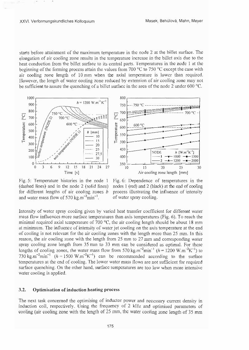
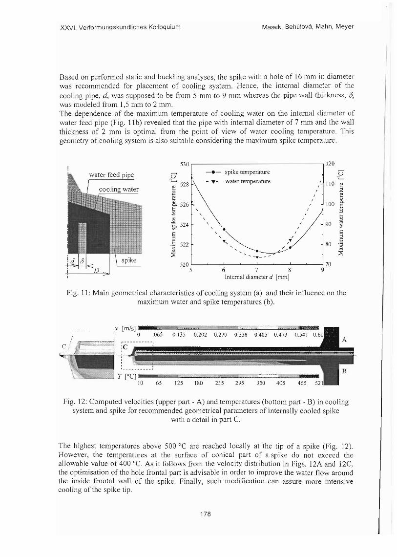
XXVI Verformungskundliches Kolloquium Masek Behulova Mahn Meyer
[11] D Jandova J Rehor and Z Novy Microstructural changes taking place during the thermo-mechanical processing and cold working of steel 18Cr18MnO5N Journal of Materials Processin g Technology Vol 157-158 2004 pp 523-530
[12] B Masek R Neugebauer U Mahn and L W Mey er Integration of a Thermoshymechanical Treatment in to the Spin Extrus ion Process Stahl und Eisen 124 No9 2004 pp 77-82
[13] H Stafikova B Masek and L W Meyer The Influence of the Incremental Deformation Intensity on the Microstructure Development In 7th International Conference on Production Engineering and De sign for Development PEDD 2006 Cairo Egypt
[14] M Behulova Simulation model of induction heating for the process of rotary spin extrusion Research Papers MtF STU Trnava Vol 152003 pp 9-18
[15] M Behulova B Masek and L W Meyer Static and dynamic induction heating shyexperiment and numerical simulation MP-Materialprtifung Vol 48 No5 2006 pp 217-224
[16] M Behulova B Masek and L W Meyer Virtual testing of the dynamic induction heating Finite elements in Analysis and De sign (to be published)
[17] M Behulova Simulation model of induction heating for the process of rotary spin extrusion Research Papers MtF STU Tmava Vol 172004 pp 9-15
[18] R Jeschar V Specht und V Heidt Mechanismen der Warmeubertragung Bei Kuhlen von Metallen mit verdamfenden Flussigkeiten Braunschweigischen Wissenschaftlichen Geselschaft Verlag Erich Goltze Gottingen 1991
180