application of intensified heat transfer for the retrofit...
TRANSCRIPT

1
Application of Intensified Heat Transfer for the Retrofit of Heat
Exchanger Network
Yufei Wang, Ming Pan, Igor Bulatov, Robin Smith, Jin-Kuk Kim
Centre for Process Integration, School of Chemical Engineering and Analytical Science, The
University of Manchester, Manchester, M13 9PL, UK
Abstract
A number of design methods have been proposed for the retrofit of heat exchanger
network (HEN) during the last three decades. Although considerable potential for energy
savings can be identified from conventional retrofit approaches, the proposed solutions are
hardly adopted in practice, due to significant topology modifications required and its
engineering complexities during implementation. The intensification of heat transfer for
conventional shell-and-tube heat exchangers can eliminate the difficulties of implementing
retrofit in HEN which are commonly restricted by topology, safety and maintenance
constraints, and includes high capital costs for replacing equipments and pipelines. This paper
presents a novel design approach to solve HEN retrofit problems based on heat transfer
enhancement. A mathematical model has been developed to evaluate shell-and-tube heat
exchanger performances, with which heat transfer coefficients and pressure drops for both
fluids in tube and shell sides are obtained. The developed models had been compared with
Bell-Delaware, simplified Tinker and Wills-Johnston methods and tested with HTRI®
and
HEXTRAN®
software packages, which demonstrates that the new model is much simpler but
can give reliable results in most cases. For the debottlenecking of HEN, five heuristic rules
are proposed to identify the most appropriate heat exchangers requiring heat transfer
enhancements in the HEN. The application of this new design approach allows a significant
improvement in energy recovery without fundamental structural modifications to the network.
Keywords: Heat exchanger network (HEN); Retrofit; Heat transfer enhancement (HTE); Heat
exchanger model; Heuristics

2
1. Introduction
Nowadays, the retrofit of heat exchanger network (HEN) is an important way of
improving energy efficiency in process industries. An industrial plant may need to be
retrofitted several times throughout its lifetime to improve energy efficiency and/or to meet
the increased production rate. There are various strategies to achieve energy savings in a
retrofit study, for example, reducing the use of utilities, modifying appropriate network
topology, upgrading heat transfer units, installing additional heat transfer area, repiping
streams and re-assigning heat recovery matches. The retrofit objective is to identify a cost-
effective HEN, subject to any design and operating constraints. However, implementing
aforementioned retrofit strategies in practice may be difficult, due to constraints related to the
topology, safety and maintenance which often exist in a complex HEN. Besides, the capital
cost is usually high because of considerable piping and civil works required for the retrofit
and potential production losses during process modification.
In recent years, heat transfer enhancement (HTE) techniques have been developed. Polley
et al. [1] addressed the application of HTE in the context of process integration. The use of
HTE in process integration has many benefits. First, enhanced heat exchangers require less
heat transfer area for a given heat duty because of higher heat transfer coefficients. Second,
the heat transfer capacity for the given heat exchanger can be increased without changing
physical size of the exchanger. Third, the use of HTE can reduce pumping requirement in
some cases as enhanced heat exchangers can achieve higher overall heat transfer coefficients
under lower velocities which may lead to less friction losses. Using HTE techniques has
practical advantages in HEN retrofit, as HTE can avoid physical modification of exchanger
itself. The implementation of HTE is a relative simple task that can be easily achieved within
a normal maintenance period when production losses can be kept in a minimum level and the
relevant civil works can be also reduced.
Design methods proposed for HEN retrofit can be divided into two groups. The first group
of methods are based on pinch analysis [1-4]. The second group of methods are based on
mathematical programming [5-9]. Polley et al. [1] applied HTE into the retrofit of heat
exchanger network and analyzed the aspects of fouling and pressure drop, but only the
potential for using enhancement techniques in the heat recovery systems was discussed
without providing systematic procedures for the implementing enhancement in the retrofitting
of heat recovery network. Zhu et al. [2] presented a methodology for applying HTE in retrofit,
based on network pinch approach. The proposed procedure aims to find out which exchanger

3
should be enhanced and the augmentation level of enhancement. However, the enhancement
devices were used only for additional area identified from the network pinch method, without
using full benefits of enhanced heat transfer. Asante and Zhu [8] developed a network pinch
method for retrofit scenarios and Smith et al. [3] further improved the method by considering
multi-segmented stream data. They combined structural modifications and cost optimisation
in a single step to achieve cost-effective design.
It is very common to use mathematical programming methods for HEN retrofit. Yee and
Grossmann [5] presented a systematic procedure for the retrofit design of HEN. They
proposed a design method using superstructure that includes all the possible structural
scenarios, and formulated an optimisation framework as mixed-integer nonlinear
programming (MINLP) model. Sorsak and Kravanja [6] proposed an MINLP optimisation
model for HEN retrofit, in which the selection of different exchanger types, such as, double
pipe exchangers (DP), shell and tube exchangers (ST), and plate and frame exchangers (PF),
was made simultaneously. Since their extended model considered different types of
exchangers, feasibility of heat transfer throughout the HEN is strongly dependent on the
choice of exchanger types, which limits the extent of heat recovery. For example, in counter-
flow heat exchangers, the outlet temperature of the cold stream can be higher, due to
geometry-characteristics of exchangers. When multiple tube passes are used for ST
exchangers, the flow arrangement combines the counter and co-current flows, and
consequently, the feasibility of heat transfer is limited by those flow patterns in the
exchangers. To overcome this problem, additional constraints were specified for ST
exchangers in their model. Ponce-Ortega et al. [7] presented a new MINLP model for HEN
synthesis with consideration of phase change in heat exchangers. Although benefits of
mathematical programming have been exploited, the application of these methods was limited
when the problem size is large and rigorous exchanger models are to be used.
Although various studies and methodologies have been proposed for HEN retrofit, most
of works assume constant heat transfer coefficients and neglect fluid pressure drops, which is
not suitable for practical application and retrofit, because heat transfer coefficients and fluid
pressure drops vary with design. Furthermore, very expensive costs associated modifications
and implementation, are not fully considered in most existing methods, and typical industrial
problems are usually too big to be effectively solved with available HEN synthesis methods.
To avoid the aforementioned disadvantage, this paper proposes a novel approach for HEN
retrofit through heat transfer enhancement. In our approach, a detailed model for heat
exchanger has been developed for calculating heat transfer coefficients and pressure drops in

4
heat exchangers, and then five heuristic rules based on expertise and knowledge in the process
engineering communities have been proposed to identify suitable heat exchangers for
employing enhanced heat transfer techniques in the HEN. Finally, the retrofit problems can be
dealt without involving complex calculations. In addition, the characteristics of real-world
engineering problems imposed on the retrofit of HEN are considered, such as variable heat
transfer coefficients, pressure drop constraints, varying stream thermal properties and detailed
geometry of heat exchangers. New design methodology aims to maximise energy saving
without topology modifications, for example, pipeline repiping, match resequencing and new
exchanger installing, and hence, no structural options other than intensified heat transfer is
considered.
The paper will address, first, a problem statement for rigorous heat exchanger modelling,
which is then followed by the descriptions of a new model for shell-and-tube exchanger, and
heuristic rules for HEN retrofit. Afterwards, the detailed heat exchanger model proposed in
this paper will be validated, and then a case study of a large scale HEN retrofit problem is
presented and solved with the proposed approach.
2. Problem statement
Since shell-and-tube heat exchanger is most widely used in process industries, it is
assumed that heat recovery in the paper is based on heat transfer through shell-and-tube
exchanger type. The heat transfer coefficient and pressure drop of each individual heat
exchanger in the network are calculated by new model proposed in this paper. Before
evaluation of detailed performance of heat exchanger, the overall configuration of HEN must
be known, and thus, the problem to be addressed in this paper is based on the following
information and assumptions.
It is assumed that the following information is given:
(1) Matches between hot streams and cold streams.
(2) The current use of utilities for heating and cooling in the existing HEN.
(3) Stream data (i.e., flowrates, inlet temperature and outlet temperature, density, specific heat
capacity, viscosity, thermal conductivity and fouling coefficient).
(4) Tube-side geometry of heat exchanger (i.e., tube length, tube inner diameter, number of
tube, number of tube passes, tube wall conductivity and nozzle inner diameters of tube-
side).

5
(5) Shell-side geometry of heat exchanger (i.e., tube outer diameter, tube pitch, tube layout
angle, shell inner diameter, number of shell passes, baffle spacing, baffle cut, shell-bundle
clearance and nozzle inner diameters of shell-side).
The design methodology for retrofitting HEN is required:
(1) To identify suitable heat exchangers for heat transfer enhancement.
(2) To calculate heat transfer coefficients of heat exchangers before and after enhancement.
(3) To calculate pressure drops of tube and shell sides for heat exchangers before and after
enhancement.
(4) To minimise the use of utilities for heating and cooling in the retrofitted HEN.
The aim with our design approach is to utilize heat transfer enhancements and
consequently to reduce the energy consumptions of HEN in which no topology modification
is needed. To derive the proposed approach for HEN retrofit, the following assumptions and
strategies are made:
(1) Heat exchange between streams in liquid phase is only used for heat exchanger model.
But it does not restrict the proposed heuristic rules to be implemented for the retrofit of
HEN in which phase change can occur in the exchanger, as long as the performance of the
exchanger can be evaluated through mathematical modeling or performance data.
(2) The type of shell-and-tube heat exchanger considered is AES, namely, front head type is
channel and removable cover (A), shell type is one pass shell (E), and rear head type is
floating heat with backing device (S).
(3) The baffle type is single segmental.
(4) Baffle cut varies 20% to 50%.
(5) Tube layout angle is 90°.
(6) Tube insert, hiTRAN®
(produced by Cal Gavin Ltd), is used for heat transfer
enhancement. Heat transfer coefficient and pressure drop of hiTRAN®
can be obtained
from software hiTRAN.SP®
(supported by Cal Gavin Ltd) [10].
To improve the heat exchanger model, heat exchange other than liquid phases (e.g.
condensation, vapour-to-liquid transfer) will be considered in the future works. So far, most common
and widely-used methods, inlcuidng Bell Delaware method, simplifed Tinker method and Wills

6
Johnsoton method only address liquid phase heat transfer. Moreover, although one type of heat
transfer enhancement and its enhancement on tube-side is only considered for HEN retrofit in
this paper, the proposed design approach is generic enough to be used for accommodating
other enhancement methods (e.g. twisted-tap tube inserts, coiled wire tube inserts, helical
baffles, etc) as well as other retrofit options, including heat transfer enhancements with both
tube and shell sides and suitable topology modifications based on the network pinch
approach.
3. Modelling of shell-and-tube heat exchanger
For predicting heat exchanger performances, it is necessary to calculate the overall heat
transfer coefficient, and pressure drop for both fluids in tube and shell side. Understanding of
fluid behaviour in the tube side is relatively straightforward, and well-known correlations,
such as Colburn correlation [11], Dittus-Boelter correlation [11] and plain tube pressure drop
method [12] are sufficiently accurate for tube-side calculations. The methods commonly used
for shell-side calculation include Bell-Delaware method [13], Developed Delaware method
[14], Chart method [15], simple Delaware method [16], simplified Tinker method [17] and
Wills-Johnston method [18]. However, those available methods for shell-side often results in
significantly different heat transfer coefficients and pressure drops, compared with
commercial software (e.g. HTRI®
), which has been accepted and widely used in the process
industries. Therefore, this study had been carried out to respond this fundamental need for
developing more reliable model for estimating performance of shell and tube exchanger.
In the new model, heat transfer coefficients and pressure drops of tube-side are calculated
firstly, and then improved models of Chart method [15] and simple Delaware method [16] are
used for shell-side calculations, the overall heat transfer coefficient, logarithmic mean
temperature difference (LMTD), LMTD correction factor (FT), and overall heat transfer area
are addressed in sequence. Fig. 1 describes the geometric details of shell-and-tube heat
exchangers and their schematic diagram which explain definition of various parameters and
sepcifications required in the calculations of heat transfer and pressure drops.

7
Fig. 1 Geometry specifics of shell-and-tube heat exchanger
3.1. Tube-side heat transfer coefficient
To calculate tube-side heat transfer coefficient, the velocity (vi), Reynolds number (Rei),
and Prandtl number (Pri) of tube side have to be obtained first, as shown in Equations (1) to
(3), where Di is tube inner diameter; im is the mass flowrate of tube-side fluid; np and nt are
the number of tube passes and tubes, respectively. For tube-side fluid properties, specific heat
capacity (Cpi), viscosity (µ i), fluid density (ρi), and thermal conductivity (ki) are evaluated at
average bulk fluid temperature, and these values are assumed to be known.
( )( )4/
/2
ii
tpi
iD
nnmv
πρ= (1)
iiiii vD µρ /Re = (2)
iiPii kC /Pr µ= (3)
Equation (4) shows the correlation of tube-side Nusselt number (Nui) based the Dittus-
Boelter correlation [11], in which some of original parameters for cooling had been updated.

8
=coolingfor Pr0.023Re
heatingfor PrRe024.04.00.8
i
4.08.0
i
iiiNu 410Re ≥i (4)
( ) ( ) ]/1[Pr125Re116.03/23/13/2
LDNu iiii +−= 410Re2100 << i (5)
( )[ ] 31/PrRe86.1 LDNu iiii = 2100Re ≤i (6)
where L is tube length.
Then, tube-side heat transfer coefficient (hi) can be calculated:
( ) iiii NuDkh ×= / (7)
3.2. Tube-side pressure drop
Tube-side pressure drop is contributed by three major elements, pressure drop due to fluid
friction in straight sections of tube (△Pfi), pressure drop due to tube entrance, exit and return
losses (△Pr), and pressure drop in nozzles (△Pni).
The pressure drop due to friction loss (△Pfi) is based on Darcy friction factor ( fi ) [12].
2585.0Re4137.0 −= iif 3000Re ≥i (8)
iif Re/64= 3000Re <i (9)
ic
iiip
fiDg
vLfnP
2
2ρ=∆ (10)
where gc is unit conversion factor which is equal to 1.0 kg·m/(N·s2).
Equations (11)-(13) presents the pressure drop related to the tube entrance, exit and return
losses (△Pr) [12]. αr is the number of velocity heads allocated for minor losses.
flowent for turbul 5.12 −= pr nα (11)
flowlaminar for 5.125.3 −= pr nα (12)
c
iir
rg
vP
25.0 ρα=∆ (13)

9
To estimate the pressure drop in nozzles (△Pni), inlet and outlet nozzles should be
considered separately, as shown in Equations (14) to (21) [12].
( )4/2
,
,
inletnii
i
inletniD
mv
πρ= (14)
i
iinletniinletni
inletni
vD
µ
ρ,,
,Re = (15)
c
inletniiS
inletnig
vNP
2
,
,
375.0 ρ=∆ for turbulent flow (16)
c
inletniiS
inletnig
vNP
2
,
,
75.0 ρ=∆ for laminar flow (17)
where vni,inlet is the velocity of inlet nozzle in tube side, Dni,inlet is the inner diameter of inlet
nozzle in tube side, NS is the number of shell passes, and △Pni,inlet is the pressure drop of inlet
nozzle in tube side.
( )4/2
,
,
outletnii
i
outletniD
mv
πρ= (18)
i
ioutletnioutletni
outletni
vD
µ
ρ,,
,Re = (19)
c
outletniiS
outletnig
vNP
2
,
,
375.0 ρ=∆ for turbulent flow (20)
c
outletniiS
outletnig
vNP
2
,
,
75.0 ρ=∆ for laminar flow (21)
where vni,outlet is the velocity of outlet nozzle in tube side, Dni,outlet is the inner diameter of
outlet nozzle in tube side, and △Pni,outlet is the pressure drop of outlet nozzle in tube side.
The pressure drop in nozzles (△Pni) can be presented as:
outletniinletnini PPP ,, ∆+∆=∆ (22)
Based on equations (8) to (22), overall tube-side pressure drop (△Pi) is obtained.

10
nirfii PPPP ∆+∆+∆=∆ (23)
3.3. Shell-side heat transfer coefficient
Ayub [15] proposed a chart method to calculate shell-side heat transfer coefficient in a
single segmental shell-and-tube heat exchanger. This method was based on a chart which was
a graphical represenation of wide range of actual exchanger data. He also demonstrated that
the results from this method agreed well with HTRI®
. However, as shell-side heat transfer
coefficient information is only presented in a chart without numerical correlations, and the
chart method cannot be readily applied in a mathematical simulation and optimisation studies.
Therefore, several new correlations, Equations (32) and (33), are set up in this section, based
on the chart presented by Ayub [15]. As shown in Ayub’s work, shell-side heat transfer
coefficient (h0) can be calculated from:
( )0
3/1
00
3/2
0
0D
CkFFFh
pLps µ= (24)
85.0=PF (25)
90.0=LF (26)
where D0 is tube outer diameter. Shell-side fluid properties, specific heat capacity (Cp0),
viscosity (µ0), fluid density (ρ0), and thermal conductivity (k0) are evaluated at average bulk
fluid temperature.
Factor Fz is defined as:
0000 µρ hz vDF = (27)
hm
hS
mv
0
0
0ρ
= (28)
where 0m is the mass flow rate of shell-side fluid; vh0 is the velocity of shell-side fluid used
for calculating heat transfer coefficient; and Shm is the shell-side crossflow area for calculating
vh0.
Shm of 90° tube layout angle is calculated as:

11
sbsotl LDD −= (29)
−=
T
otl
PT P
DDevenN 0
90, o (30)
( )
−+
−−= 090,
090,
90, 2DPN
DPNDBS TPT
TPTs
hm o
o
o (31)
where function Xeven returns the largest even number not larger than X, Lsb is the diameter
clearance between shell and tube bundle, Dotl is bundle outer diameter, PT is tube pitch, and B
is central baffle spacing.
The relationship of factors Fs, Fz and baffle cut (Bc) is given in the chart proposed by
Ayub [15], in which Fs is the function of Fz and Bc. The correlations of Fs, Bc and Fz are
formulated as:
793.1778.762223.9 2 ++−= zzs FFF , 2≤zF (32)
5053.06633.04783.34
−= czs BFF , 10002 ≤< zF (33)
3.4. Shell-side pressure drop
Simplified Delaware method [16] uses less empirical equations, but provides accurate
results [12], compared to other methods, for the wide operaing range of shell-side diameter
and flow velocity. Simplified Delaware method [16] is a relatively simple method, but only
suitable for 20% baffle cut scenarios. In this section, new additional correlations of shell-side
cross-flow area (Equations (35) and (36)) and the relationships between pressure drop and
baffle cut (Equations (45) to (47)) are added to guarantee that simplified Delaware method
can be used for a larger baffle cut. Shell-side pressure drop consists of the pressure drop due
to fluid friction in straight section of shell (△Pf0), and the pressure drop in nozzles (△Pn0).
Equation (34) is based on simplified Delaware method, which presents the pressure drop
in one central baffle spacing when baffle cut is 20% (△Pfb,20%Bc).
ec
ps
BcfbDg
vDfP
2
2
000
%20,
ρ=∆ (34)
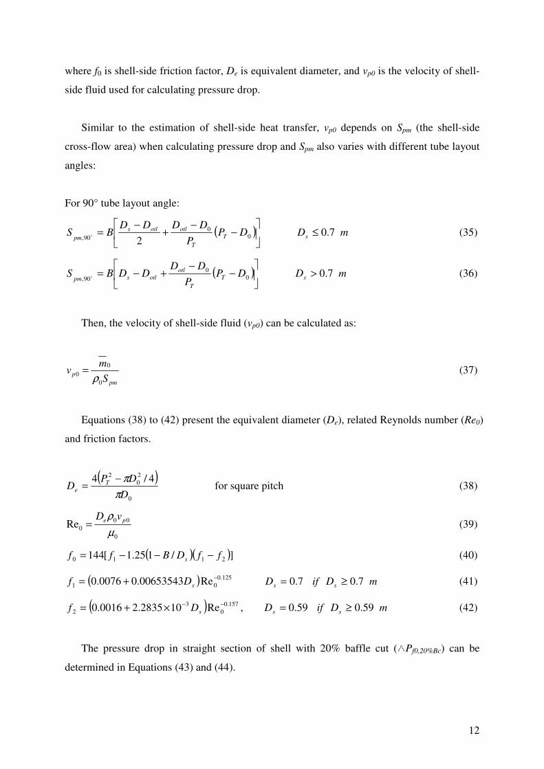
12
where f0 is shell-side friction factor, De is equivalent diameter, and vp0 is the velocity of shell-
side fluid used for calculating pressure drop.
Similar to the estimation of shell-side heat transfer, vp0 depends on Spm (the shell-side
cross-flow area) when calculating pressure drop and Spm also varies with different tube layout
angles:
For 90° tube layout angle:
( )
−
−+
−= 0
0
90, 2DP
P
DDDDBS T
T
otlotls
pm o mDs 7.0≤ (35)
( )
−
−+−= 0
0
90,DP
P
DDDDBS T
T
otl
otlspm o mDs 7.0> (36)
Then, the velocity of shell-side fluid (vp0) can be calculated as:
pm
pS
mv
0
0
0ρ
= (37)
Equations (38) to (42) present the equivalent diameter (De), related Reynolds number (Re0)
and friction factors.
( )0
2
0
24/4
D
DPD T
eπ
π−= for square pitch (38)
0
00
0Reµ
ρ pe vD= (39)
( )( )]/125.1[144 2110 ffDBff s −−−= (40)
( ) 125.0
01 Re00653543.00076.0−+= sDf mDifD ss 7.07.0 ≥= (41)
( ) 157.0
0
3
2 Re102835.20016.0−−×+= sDf , mDifD ss 59.059.0 ≥= (42)
The pressure drop in straight section of shell with 20% baffle cut (△Pf0,20%Bc) can be
determined in Equations (43) and (44).

13
( )fbsfbbBcf PRPnP ∆+∆−=∆ 1%20,0 (43)
( ) ( ) 8.18.1// outins BBBBR += (44)
where Rs is the correction factor for unequal baffle spacing, B is central baffle spacing, Bin
and Bout are inlet and outlet baffle spacing, respectively.
To consider the pressure drop in straight section under different baffle cuts (△Pf0), new
correlations are proposed in Equations (45) to (47).
( ) 26765.0
%20,00 %20/−
∆=∆ cBcff BPP , %30%20 ≤< cB (45)
( ) 36106.0
%20,00 %20/−
∆=∆ cBcff BPP , %40%30 <≤ cB (46)
( ) 58171.0
%20,00 %20/−
∆=∆ cBcff BPP , %50%40 ≤≤ cB (47)
The pressure drop in shell-side nozzles can be determined in the same correlations as
calculating the pressure drops in tube-side nozzles.
( )4/2
,00
0
,0
inletn
inletnD
mv
πρ= (48)
0
0,0,0
,0Reµ
ρinletninletn
inletn
vD= (49)
c
inletnS
inletng
vNP
2
,00
,0
375.0 ρ=∆ for turbulent flow (50)
c
inletnS
inletng
vNP
2
,00
,0
75.0 ρ=∆ for laminar flow (51)
where vn0,inlet is the velocity of inlet nozzle in shell side, Dn0,inlet is the inner diameter of inlet
nozzle in shell side, NS is the number of shell passes, and △Pn0,inlet is the pressure drop of inlet
nozzle in shell side.
( )4/2
,00
0
,0
outletn
outletnD
mv
πρ= (52)
0
0,0,0
,0Reµ
ρinletnoutletn
outletn
vD= (53)

14
c
outletnS
outletng
vNP
2
,00
,0
375.0 ρ=∆ for turbulent flow (54)
c
outletnS
outletng
vNP
2
,00
,0
75.0 ρ=∆ for laminar flow (55)
where vn0,outlet is the velocity of outlet nozzle in shell side, Dn0,outlet is the inner diameter of
outlet nozzle in shell side, and △Pn0,outlet is the pressure drop of outlet nozzle in shell side.
The pressure drop in nozzles (△Pn0) can be presented as:
outletninletnn PPP ,0,00 ∆+∆=∆ (56)
Based on above equations, shell-side pressure drop (△P0) is obtained.
000 nf PPP ∆+∆= (57)
3.5. U, LMTD, FT and A
The overall heat transfer coefficient (U) can be calculated with Equation (58), where ktube
is tube conductivity; RDi and RD0 are fouling resistances of tube side and shell side,
respectively.
( )1
0
0
0
000 1
2
/ln−
++++= D
i
Di
tube
i
ii
RD
DR
hk
DDD
Dh
DU (58)
Before logarithmic mean temperature difference (LMTD) is considered, the outlet
temperature of shell side (T0,outlet) is set as an initial estimated value, and then this will be
iterated and updated accordingly, and the outlet temperature of tube side (Ti,outlet) can be
calculated based on energy balances.
( ) ( )inletioutletipiiinletoutletp TTCmTTCm ,,,0,000 −=− (59)
where T0,inlet is the inlet temperature of shell side, and Ti,inlet is the inlet temperature of tube
side.

15
LMTD is the mean temperature difference between the two fluid streams, which is shown
in Equation (60).
inletioutlet
outletiinlet
inletioutletoutletiinlet
TT
TT
TTTTLMTD
,,0
,,0
,,0,,0
ln−
−
−−−= (60)
In multi-tube-pass heat exchangers, the flow pattern includes both counter and co-current
flows and, therefore, the mean temperature difference is not equal to the logarithmic mean
when tube passes are more than one, and the correction factor of LMTD (FT) is used [12].
inletioutleti
outletinlet
TT
TTR
,,
,0,0
−
−= (61)
inletiinlet
inletioutleti
TT
TTP
,,0
,,
−
−= (62)
For 1≠R :
sN
P
RP/1
1
1
−
−=α (63)
RS
−
−=
α
α 1 (64)
( ) ( )( )
+++−
+−+−−
−
−+
=
112
112ln1
1
1ln1
2
2
2
RRS
RRSR
RS
SR
FT (65)
For R = 1:
( )PNN
PS
ss 1−−= (66)

16
( ) ( )( )
+−
−−−
=
222
222ln1
2
S
SS
SFT (67)
Based on above calculation, the overall heat transfer area can be determined in two ways.
One is based on the geometry of heat exchanger (A), and the other is based on the overall heat
transfer coefficient (A’). They are presented in Equations (68) and (69), respectively.
efft LDnA 0π= (68)
where Leff is the tube effective length.
LMTDFTU
TTCmA
outletinletp
××
−=′
,0,000
(69)
3.6. Iteration
Since the outlet temperature of shell side (T0,outlet) is assumed, the overall heat transfer
area based on this temperature (A’) is not usually identical to the overall heat transfer area
based on heat exchanger geometry (A). For this reason, an iteration loop from Equations (59)
to (69) is proposed to find a suitable outlet temperatures of shell side until the values of A and
A’ are converged, which is usually converged after several iterations.
4. Heuristic rules for HEN retrofit with HTE
In this paper, HEN retrofit problems considers aspects of the reduction in the use of
utilities, number of heat exchangers to be enhanced, enhancement details of each heat
exchanger and pressure drop constraints. As there are a large number of potential exchanger
enhancement options included in a HEN, estimating the efficiency for all these options is not
straightforward. Moreover, safety and operability play an important role in the decision for
retrofitting. These factors are qualitative in nature, and although they cannot be expressed
explicitly, they must be traded off against other design requirements. To solve complex and
large-scale problems, solution strategies for solving optimisation problems can be benefited

17
by considering heuristic rules [19-21]. In this section, several heuristic rules are proposed for
HEN retrofit to identify the exchangers to be enhanced.
4.1. Rule 1: searching for exchangers in utility path
Candidates are those exchangers which may increase heat recovery in a HEN after heat
transfer enhancements are implemented. Based on pinch method, only if an exchanger is on
utility path, the consumption of utility can be reduced by increasing the duty of exchanger
without changing the target temperature of streams [22-24]. If it is desired to retrofit the
network without any topology modifications, changing the duty of exchangers through utility
path is the only way. So, first of all, the candidates should be on utility path. Fig. 2 is used to
illustrate the procedure of searching exchangers in utility path. As shown in Fig. 2, every
exchanger is on a utility path. After checking utility path, there are, in general, many
candidate exchangers to be further examined. The exchangers on the same stream with a
utility exchanger can affect the duty of the utility exchanger directly. And these exchangers
should be selected. For example, if a reduction of hot utility is required, exchangers 1, 2, 4
and 5 should be selected to the next step analysis, because all of these exchangers are
involved to raise the temperature of the cold stream (C2).
There are four utility paths: exchangers 6, 1 and 8; exchangers 6, 2 and 7; exchangers 6, 4 and
10; exchangers 6, 5 and 9.
Fig. 2 A heat exchanger network
1 N:1
2 N:2
230
3 N:3
200
4 N:4
300
5N:5
100
6N:6
80
7 N:7
400
8N:8
25
2
2
N:11
N:12
3
3
N:13
N:14
7
7
N:19
N:20
1
1
N:9
N:10
8
8
N:21
N:22
5
5
N:23
N:24
9
9
N:25
N:26
4
4
N:15
N:16
10
10
N:27
N:28
6
6
N:17
N:18
H1
H2
H3
H4
C1
C2
Hot utility
Cooling Water
Hot stream: Cold stream: Heat exchanger:

18
4.2. Rule 2: sensitivity analysis
After heat exchangers are selected with Rule 1, sensitivity tables presented by
Kotjabasakis and Linnhoff [25] is used to quantify impact of heat transfer intensity on utility
consumption of the HEN. Sensitivity table is based on a simple heat transfer equation1 , in
which only stream data and network structure are needed.
Assume that the inlet temperature of cold utility in a HEN is the response parameter, the
change of temperatures for utility exchangers related to utility path will be known, when the
UA value (heat transfer coefficient, U, multiplied by area, A) of candidate exchangers is
changed. The best candidate exchanger can be found if its response parameter has high
sensitivity. As shown in Fig. 3, exchanger 2 is a good candidate, since with 25% increment of
UA value, the inlet temperature of cold utility almost increase 4ºC. On the contrary,
exchanger 3 is not a good candidate because, with 25% increment of UA value, the inlet
temperature of utility increases slightly. Sensitivity analysis is the key basis of the proposed
work, which can help to indentify the exchangers with large energy saving potential.
Fig. 3 Sensitivity graphs of exchangers 2 and 3
1 Q = U·A·∆TLM, where Q is the overall heat transfer load, U is overall heat transfer coefficient, A is heat
exchanger area, ∆TLM is the log-mean temperature difference.

19
Fig. 4 Maximum heat recovery in a heat exchanger
To explain why high sensitivity exchanger can be a good candidate, Fig. 4 is used to
shows the maximum heat recovery in a heat exchanger, where the red line indicates the hot
stream, and the blue line indicates the cold stream. In the figure, the slope of line is the
reciprocal value of CP (heat-flow capacity which is the multiplication between heat capacity
and flowrate) for each stream, and the equation of maximum heat recovery in an exchanger is
given as:
minmax CPTQ initial∆=∆ (70)
where ∆Qmax is the maximum heat recovery, ∆Tinitial is the initial temperature difference
between the inlet of high CP stream and the outlet of low CP stream, and CPmin is CP value of
the stream that has lower CP in the exchanger.
From equation (70), energy saving depends on CPmin and ∆Tinitial. If a heat exchanger on
utility path is enhanced, then for the exchanges between the enhanced one and utility
exchanger, the heat transfer is reduced, due to small heat transfer driving force. In other word,
the exchanger with large CPmin and ∆Tinitial, and close to utility exchanger can be a high
sensitivity heat exchanger.
The objective of this methodology is to find the best candidate. Very good candidates can
be easily identified. Although a systematic way to distinguish which exchangers are good for
enhancement has been proposed, the proposed method is based on heuristics, not

20
deterministic approach, which requires users’ judgement and decision. Application of
optimisation techniques would be possible for the improvement.
4.3. Rule 3: checking pinching match
From the network concept presented by Asante and Zhu [8], it can be noted that pinching
match is the bottleneck of heat recovery network. A pinching match is defined as an
exchanger match where the temperature approach between hot and cold streams unavoidably
tends towards a limiting value as the heat recovery in the HEN is increased. Normally, the
pinching match will have a very small heat transfer temperature difference. When the heat
recovery of the network is further to be increased, heat transfer temperature difference for the
pinching match will go towards zero. If a pinching match is a downstream2 exchanger of the
candidate, then the candidate is not promising.
4.4. Enhancing several candidates simultaneously
Sometimes, only enhancing one exchanger may not achieve considerable energy savings.
Normally, with Rules 1, 2 and 3, more than one good candidate can be identified and this
provides a good opportunity for further improvement in the energy recovery. It is obvious that
when one candidate is enhanced, all of its downstream exchangers will be affected. Therefore,
after an exchanger is enhanced, sensitivity analysis is applied again to all candidate
exchangers to find the next best one.
4.5. Rule 4: enhancing pinching match
Sometimes, no good candidate for the heat transfer enhancement exists, or potential for
energy savings from enhancing promising candidates may be very low. In this situation,
enhancing pinching match can be considered. As low driving force for heat transfer in
pinching match is bottleneck for the enhancement of candidate exchanger, enhancing
pinching match can be a good option to compensate the loss of heat transfer driving force
after the candidates are enhanced.
2 For this study, if a stream exited from exchanger A goes into exchanger B, then exchanger B is located in the
downstream of exchanger A.

21
Based on the heuristic rules 1-5, suitable candidates in HEN are selected, and the detailed
performances of these exchangers before and after enhancement can be calculated with the
developed heat exchanger model. The procedure of the proposed approach is shown in Fig.5.
Fig. 5 Procedure of the proposed retrofit approach
5. Case studies
The semi-rigorous heat exchanger model developed in this paper is validated at first. Then,
an industrial-scale HEN retrofit problem is presented and applicability and robustness of the
proposed retrofit approach is demonstrated.
Network structure analysis
Search exchangers in utility path (Heuristic rule 1)
Sensitivity analysis (Heuristic rule 2)
Check the pinching match (Heuristic rule 3)
Enhance the candidate exchanger
Any other good candidates?
Yes
No
Still need improvement? Enhance pinching match
(Heuristic rule 4)
Yes
Result
No

22
5.1 Performance evaluation of heat exchanger model
The proposed heat exchanger model are compared with three models, namely, Bell-
Delaware [13], simplified Tinker [17] and Wills-Johnston [18] and two commercial software,
namely, HTRI®
and HEXTRAN®
. The details of methods used in the models are presented in
Table 1. Tables 2 and 3 show stream properties and geometry details of heat exchangers used
in Examples 1-10.
Table 1 Method details of the compared models
Table 2 Stream data and geometry of heat exchangers: Examples 1-5

23
Table 3 Stream data and geometry of heat exchangers: Examples 6-10
Table 4 Modelling Results: Examples 1-3

24
Table 5 Modelling Results: Examples 4-6
Table 6 Modelling Results: Examples 7-10
As shown in Tables 4 to 6, stream temperatures, heat transfer coefficients and pressure
drops calculated from the proposed model are similar to values obtained by HTRI®
and
HEXTRAN®
in most cases. Three models considered in this paper (M1, M2 and M3) may
give significantly different results, compared with HTRI®
and HEXTRAN®
.
As shown in the tube-side results from the developed model, HTRI®
and HEXTRAN®
,
major difference is in heat-transfer coefficients. The developed model and HTRI®
method
usually give higher values than HEXTRAN®
which may use Colburn correlation (i.e. Nu =
0.023Re0.8
Pr1/3
) [11] to calculate tube-side heat-transfer coefficient. Compared with Equation
(4), the Colburn correlation uses a smaller factor to calculate Nusselt number (Nui). For

25
calculating pressure drop, plain tube pressure drop method [12] is used, the values predicted
by the proposed model have reasonably a good agreement with those from HTRI®
and
HEXTRAN®
.
In shell-side calculations, the developed model and HTRI®
give similar values in most
examples. HEXTRAN®
uses different correlations for the heat transfer coefficient and friction
factor of ideal tube bank, while HTRI®
includes a large number of empirical parameters for
heat transfer and flow resistance, and with many adjustable parameters, HTRI®
model can
provide a good representation of the experimental data for shell-side heat transfer and
pressure drop [12]. From Examples, it has been demonstrated that the proposed model can be
used in process engineering and design practice with confidence for predicting heat exchanger
performance.
5.2 HEN retrofit with HTE
Fig. 6 presents an existing preheat train for a crude oil distillation column in a refinery
plant. The retrofit objective is to reduce the hot utility (H13) consumption, namely, reduce the
heat duty of heat exchanger 30 (target exchanger). The initial data of the HEN can be found in
Table 7. Based on these data, the proposed heuristic rules can be utilized to find suitable heat
exchangers for enhancement.
Fig. 6 A HEN for case study

26
From Rule 1: Heat exchangers 4, 22, 23, 24, 26, 27, 28 and 29 locating in the same path
with the target exchanger are selected for performing sensitivity analysis.
From Rule 2: Fig. 7 presents the sensitivity graphs for all the selected exchangers.
Exchanger 24, 26 and 28 with high sensitivity are regarded as good candidates, exchangers 27
and 29 are normal candidates, and exchangers 4 and 23 are bad candidates with low
sensitivity. As having large CPmin and there is only one exchanger between exchanger 28 and
target utility exchanger, exchanger 28 is the best candidate. Although exchanger 29 is in
nearest position to target utility exchanger, it is not the best candidate due to its normal
sensitivity results.
From Rule 3: Exchangers 20, 22 and 23 are pinching match in the HEN. Pinching match
of Exchanger 20 is in the downstream of promising candidate Exchanger 24, therefore,
Exchanger 24 is constrained by the pinching match.
Fig. 7 Sensitivity graphs of exchangers in the case study
From the results of sensitivity table, exchanger 24, 26 and 28 are good candidates. From
Rule 3, exchanger 24 is constrained by pinching match exchanger 20 and exchanger 28 is the
best candidate without being constrained by a pinching match. Exchanger 28 should be
enhanced first, and then after applying sensitivity table again, exchanger 26 is the next best
27
candidate after the enhancement of exchanger 28. After the enhancement of both exchangers
26 and 28, there is no good candidate left from the results of sensitivity table. Rule 4 is now
applied to check whether further energy saving can be made. From the results of previous
rules, exchanger 24 is a good candidate constrained by a pinching match exchanger 20. So,
according to rule 4, both exchanger 24 and exchanger 20 are enhanced.
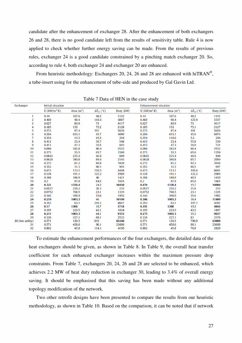
From heuristic methodology: Exchangers 20, 24, 26 and 28 are enhanced with hiTRAN®
,
a tube-insert using for the enhancement of tube-side and produced by Gal Gavin Ltd.
Table 7 Data of HEN in the case study
To estimate the enhancement performances of the four exchangers, the detailed data of the
heat exchangers should be given, as shown in Table 8. In Table 9, the overall heat transfer
coefficient for each enhanced exchanger increases within the maximum pressure drop
constraints. From Table 7, exchangers 20, 24, 26 and 28 are selected to be enhanced, which
achieves 2.2 MW of heat duty reduction in exchanger 30, leading to 3.4% of overall energy
saving. It should be emphasised that this saving has been made without any additional
topology modification of the network.
Two other retrofit designs have been presented to compare the results from our heuristic
methodology, as shown in Table 10. Based on the comparison, it can be noted that if network

28
pinch is not enhanced (the second design), the energy saving will decrease significantly. And
when one more normal candidate (exchanger 29) is enhanced (the thrid design), the energy
saving does not increase much.
Table 8 Stream data and geometry of heat exchangers 20, 24, 26 and 28 in the case study
Table 9 Tube-side heat transfer enhancement for heat exchangers 20, 24, 26 and 28 in the case study

29
Table 10 Comparison between different retrofit designs
Retrofit design number Enhanced exchangers Energy saving(kW)
1 Exchangers 20, 24, 26, 28 2240
2 Exchangers 24, 26, 28 1327
3 Exchangers 20, 24, 26, 28, 29 2654
6. Conclusion
Selecting suitable exchangers for enhancement is an efficient way to solve large-scale
HEN retrofit problems. This paper presents a new approach for HEN retrofit with HTE. First
of all, a mathematical model has been developed to predict shell-and-tube heat exchanger
performances, with which heat transfer coefficients and pressure drops for both fluids in tube-
side and shell-side can be estimated with satisfactory accuracy. And then, five heuristic rules
have been proposed to screen candidates for heat transfer enhancement of exchangers in
HEN, which can reduce problem complexity significantly. In contrast to the available design
methods, the proposed retrofit approach provides realistic solutions for HEN retrofit based on
intensified heat transfer with substantial energy saving without topology modification of
HEN. A real industrial case study shows that, based on the new approach, about 3.4% of
energy reduction has been achieved in such a high energy consumption network. To extend
the new approach, more retrofit aspects, shell-side enhancement and capital costing will be
addressed in the future work.
Nomenclature
v flow velocity
Re Reynolds number
Pr Prandtl number
Di tube inner diameter
D0 tube outer diameter
m mass flow-rate
np tube passes
nt number of tubes
Cp specific heat capacity
µ viscosity
ρ density
k thermal conductivity
Nu Nusselt number
L tube length
h heat transfer coefficient △P total pressure drop △Pf pressure drop due to fluid friction in straight sections

30
△Pr pressure drop due to tube entrance, exit and return losses △Pn pressure drop in nozzles
fi Darcy friction factor
gc unit conversion factor, 1.0 kg·m/(N·s2)
αr number of velocity heads allocated for minor losses
Dn nozzle inner diameter
NS number of shell passes
Fz Reynolds number in shell side for heat transfer coefficient
Shm shell-side crossflow area for heat transfer coefficient
NPT number of tubes in the centre of shell
Lsb diameter clearance between shell and tube bundle
Dotl bundle outer diameter
PT tube pitch
B central baffle spacing
Fs shell side geometry factor
Fp tube pitch factor
FL leakage factor
Bc baffle cut △Pfb,20%Bc pressure drop in one central baffle spacing when baffle cut is 20%
f0 shell-side friction factor
De equivalent diameter
Spm shell-side crossflow area for pressure drop △Pf0,20%Bc pressure drop in straight section of shell with 20% baffle cut
Rs correction factor for unequal baffle spacing
Bin inlet baffle spacing
Bout outlet baffle spacing
U overall heat transfer coefficient
ktube tube conductivity
RD fouling resistances
LMTD logarithmic mean temperature difference
T temperature
FT correction factor of LMTD
A overall heat transfer area based on the geometry of heat exchanger
A’ overall heat transfer area based on the overall heat transfer coefficient
Leff tube effective length
∆Qmax maximum heat recovery
∆Tinitial initial temperature difference between the inlet of high CP stream and
the outlet of low CP stream
CPmin CP value of the stream that has lower CP in the exchanger
Subscripts
i tube side
0 shell side
n nozzle
inlet inlet
outlet outlet
31
References
[1] Polley GT, Reyes Athie CM, Gough M. Use of heat transfer enhancement in process
integration. Heat Recovery Systems and CHP 1992; 12(3): 191-202.
[2] Zhu X, Zanfir M, Klemes J. Heat transfer enhancement for heat exchanger network
retrofit. Heat Transfer Engineering 2000; 21(2): 7-18.
[3] Smith R, Jobson M, Chen L. Recent development in the retrofit of heat exchanger
networks. Chemical Engineering Transactions 2009; 18: 27-32.
[4] Li BH, Chang CT. Retrofitting heat exchanger networks based on simple pinch analysis.
Industry and Engineering Chemistry Research 2010; 49: 3967-3971.
[5] Yee TF, Grossmann IE. A screening and optimization approach for the retrofit of heat
exchanger networks. Industry and Engineering Chemistry Research 1991; 30 (1): 146-
162.
[6] Sorsak A, Kravanja Z. MINLP retrofit of heat exchanger networks comprising different
exchanger types. Computers and Chemical Engineering 2004; 28: 235-251.
[7] Ponce-Ortega JM, Jiménez-Gutiérrez A, Grossmann IE. Optimal synthesis of heat
exchanger networks involving isothermal process streams. Computers and Chemical
Engineering 2008; 32: 1918-1942.
[8] Asante NDK, Zhu XX. An automated approach for heat exchanger network retrofit
featuring minimal topology modifications. Computers and Chemical Engineering 1996;
20: S7-S12.
[9] Kovac KA. Optimization of an industrial retrofitted heat exchanger network, using a
stage-wise model. Energy 2010 (In press); doi:10.1016/j.energy.2010.09.016.
[10] Cal Gavin Ltd. hiTRAN®
thermal systems: changing fluid dynamics and harnessing the
benefits. Technical report of Cal Gavin Ltd, 2009.
[11] Bhatti MS, Shah RK. Turbulent and transition convective heat transfer in ducts, in
Handbook of Single-Phase Convective Heat Transfer, S. Kakac, R. K. Shah, and W.
Aung, eds., Wiley, New York, 1987; Chap. 4.
[12] Serth RW. Design of shell-and-tube heat exchangers, in Handbook of Process Heat
Transfer Principles and Applications, R. W. Serth, eds., Elsevier Ltd, 2007; Chap. 5.
[13] Taborek J. Shell-and-tube heat exchangers, in Heat Exchanger Design Handbook,
Hemisphere Publishing Corp., New York, 1988; Vol. 3.
[14] Gnielinski A, Zukauskas A, Skrinska A. Banks of plain and finned tubes, in Heat
Exchanger Design Handbook, Hemisphere Publishing Corp., New York, 1998; Vol. 2.

32
[15] Ayub ZH. A new chart method for evaluating single-phase shell side heat transfer
coefficient in a single segmental shell and tube heat exchanger. Applied Thermal
Engineering 2005; 25: 2412-2420.
[16] Kern DQ, Kraus AD. Extended Surface Heat Transfer, McGraw-Hill, New York, 1972.
[17] ESDU Ltd. Baffled shell-and-tube heat exchangers; flow distribution, pressure drop and
heat transfer coefficient on the shell side, ESDU International Ltd, London, 1984.
[18] Wills MJN, Johnston D. A New and Accurate Hand Calculation Method for Shell-side
Pressure Drop and Flow Distribution, Proc. 22nd National Heat Transfer Conference,
American Society of Mechanical Engineers, 1984; 36: 67-79.
[19] Pan M, Qian Y, Li X. A novel precedence-based and heuristic approach for short-term
scheduling of multipurpose batch plants. Chemical Engineering Science 2008; 63: 4313-
4332.
[20] Pan M, Li X, Qian Y. New approach for scheduling crude oil operations. Chemical
Engineering Science 2009; 64: 965-983.
[21] Pan M, Li X, Qian Y. Continuous-time approaches for short-term scheduling of network
batch processes: Small-scale and medium-scale problems. Chemical Engineering
Research and Design 2009; 87: 1037-1058.
[22] Linnhoff B, Townsend DW, Boland D, Hewitt GF, Thomas BEA, Guy AR, Marsland
RH. A User Guide on Process Integration for the Efficient Use of Energy, IChemE,
Rugby, UK, 1982.
[23] Linnhoff B, Hindmarsh E. The Pinch Design Method of Heat Exchanger Networks.
Chemical Engineering Science 1983; 38: 745-763.
[24] Varbanov PS, Klemes J. Rules for paths construction for HENs debottlenecking. Applied
Thermal Engineering 2000; 20(15): 1409-1420.
[25] Kotjabasakis E, Linnhoff B. Sensitivity Tables for the Design of Flexible Processes (1)-
How Much Contingency in Heat Exchanger Networks is Cost-Effective. Chemical
Engineering Research and Design 1986; 64(a): 197-211.