application of potential theory in calculating wave
TRANSCRIPT
Archives of Hydro-Engineering and Environmental MechanicsVol. 53 (2006), No. 1, pp. 49–69
© IBW PAN, ISSN 1231–3726
Application of Potential Theory in Calculating Wave-Induced
Vertical Forces on Horizontal Cylinders Near a Plane
Boundary
Tomasz MarcinkowskiŁ, Piotr WildeŁŁ
ŁGdańsk University of Technology, Faculty of Civil and Environmental Engineering,
ul. G. Narutowicza 11/12, 80-952 Gdańsk, Poland, e-mail: [email protected]ŁŁPolish Academy of Sciences, Institute of Hydro-Engineering (IBW PAN)
ul. Kościerska 7, 80-328 Gdańsk, Poland
(Received July 07, 2005; revised March 02, 2006)
Abstract
Hydrodynamic forces acting on a horizontal cylinder located in the vicinity of thebottom are analyzed by a diffraction theory which solves the problem in terms ofa velocity potential. The cylinder is assumed to be rigidly anchored to the bottom ata sufficient depth, so that it has no influence on the surface profile. The potentialfunction � is defined as the sum of the incident wave velocity potential �w and thescattered wave velocity potential �a . The results of measurements of wave-inducedpressures and forces on a horizontal cylinder located close to the bottom are com-pared with the theoretical solution based on the potential theory for incompressible,perfect fluid and ideal boundary conditions at the bottom and the surface of thecylinder. The experiments were carried out in the Large Wave Channel in Hannoverwith a cylinder of 0.8 m diameter. Thus the results are in a scale which corresponds toreal pipelines. The analysis shows that the potential theory explains the componentswith double frequency of the wave in pressures and vertical forces as far as the amp-litudes are concerned. In the experiments, the Keulegan-Carpenter number is ratherlow and the inertia hydrodynamic forces on the cylinder are dominant. It seems thatthe observed phase shift between the force component and the wave results from theenergy dissipation which is not considered in the theoretical solution.
Key words: hydrodynamic forces, underwater pipeline, potential theory, diffractiontheory, curvilinear coordinates
1. Introduction
The problem of flow around a cylinder has a long history. A good summaryof solutions of the potential theory in complex function formulation is given byMuller (1928). This theory is used in the analysis of cylinders near a plane bot-tom by Carpenter (1958), Yamamoto et al (1974), Wright and Yamamoto (1979),Chakrabarti (1987), Sumer and Fredsøe (1997).

50 T. Marcinkowski, P. Wilde
One cannot expect a perfect solution within the potential theory for incom-pressible, perfect fluid and ideal boundary conditions. Further assumption is thatthe ratio of the submerged depth to the cylinder radius is big enough, so the influ-ence of the reflection on the free surface elevation can be neglected. Therefore,this solution cannot describe the complicated real behaviour. The authors believethat viscosity must be important, especially for processes near the seabed in con-nection with a cylinder; even more, the vortex shedding at the cylinder and bottommight have a considerable influence. Nevertheless the present theory seems to beuseful in explaining some other features. However, the application of the the-ory in complex function formulation is difficult as far as extension is concerned.Therefore, the authors decided to look at the solution by applying curvilinear co-ordinates. A good and useful presentation of curvilinear coordinates is given byMoon and Spencer (1971).
2. Theoretical Consideration
The bi-cylindrical coordinates form the traditional coordinate system, suitable forthe discussed problem (Fig. 1). The cartesian coordinates x , y are expressed interms of the bi-cylindrical coordinates u and v by the following relations:
x Da Ð sinh u
cosh u � cos v; y D
a Ð sin v
cosh u � cos v; (1)
where a is a constant.
The parameters depend on the radius of the cylinder being R and the gapbetween the cylinder and the bottom e (Fig. 1). From these conditions follows:
cosh uR D 1 Ce
R; a D R sinh uR; (2)
where uR is the value of the coordinate u for which x.v/ and y.v/ describe thesurface of the cylinder with v in the interval (�³ , ³/. When gap e goes to zero,expressions (1) yield unidentified values. Let us introduce new variables uŁ andvŁ by the following definition:
u Dr
2e
RuŁ; v D
r
2e
RvŁ: (3)
When e goes to zero the new variables have limits; appropriate calculationslead to the following expressions for the curvilinear coordinates (1):
x D2RuŁ
uŁ2 C vŁ2; y D
2RvŁ
uŁ2 C vŁ2: (4)
The relations obtained are the corresponding expressions for the tangentialcylinder coordinates multiplied by 2R (Moon and Spencer 1971). The surface of

Application of Potential Theory in Calculating Wave-Induced Vertical Forces : : : 51
Fig. 1. Bipolar coordinate system

52 T. Marcinkowski, P. Wilde
the cylinder corresponds to uŁR D 1. It is obvious from the above, that an ana-
lysis for small gaps has to be carried out carefully as the transition goes throughunidentified symbols.
Fig. 2. Sign convention
In the analysis it is convenient to work simultaneously with polar coordinatesas shown in Fig. 2. It follows that:
sin Þ D
q
2eR
.1 C eR
/
1 C eR
� cos vsin v; cos Þ D
.1 C eR
/ cos v � 1
1 C eR
� cos v(5)
and for the limiting case e ! 0:
sin Þ D2vŁ
1 C vŁ2; cos Þ D
1 � vŁ2
1 C vŁ2: (6)
The points v D 0 and vŁ D 0 are at the top of cylinder and correspond to Þ D 0.Points v D ³ and vŁ ! 1 are at the bottom of the cylinder and correspond toÞ D ³ .
The bi-cylindrical and tangential cylinder coordinate systems are orthogonal,and the corresponding metric tensors are:
pguu D
pgvv D
a
cosh u � cos v; (7)
pguŁuŁ D
pgvŁvŁ D
2R
uŁ2 C vŁ2: (8)
If � is a potential function and �!n denotes a unit outward normal to the
cylinder and�!t is a unit tangential vector which points in the direction of the
increase of Þ, then the normal and tangential velocity components are expressedby the formulae:

Application of Potential Theory in Calculating Wave-Induced Vertical Forces : : : 53
vn D �1
pguu
@�
@u; vt D
1p
guu
@�
@v: (9)
The potential function for the perfect fluid satisfies the Laplace equation,which in bi-cylindrical coordinates takes the following form:
1
guu
�
@2�
@u2C
@2�
@v2
½
D 0: (10)
The same relations as given in (9) and (10) are true for the tangential cyl-indrical coordinates when u and v are replaced by uŁ and vŁ.
As guu 6D 0 and guŁuŁ 6D 0, it follows from equation (10) that the Laplace equa-tion has the same form in both curvilinear coordinate systems and a cartesiancoordinate system. The same solution obtained by the separation of variablesmay be applied to the curvilinear coordinate systems. For the case considered inthis paper, the appropriate solution in terms of a Fourier series which satifies theLaplace equation is:
� D A Ð u C1
X
rD1
cosh.ru/[Ar cos.rv/ C Br sin.rv/]: (11)
The normal velocity component at the cylinder surface van given by equation
(9) with the potential � yields:
van D �
1p
guu
(
A C1
X
rD1
r Ð sinh.ruR/[Ar cos.rv/ C Br sin.rv/]
)
: (12)
The sums of the normal velocity components – one resulting from approachingwaves (denoted by vw
n / and the other resulting from additional potential (denotedby va
n/ – are equal to zero at each point on the cylinder surface.The values of constants A, Ar , Br are calculated by numerical method while the
values of normal velocity components van are defined by taking a limited number
of series elements according to equation (12). Hence it is advisable to introducea clearly defined measure of solution accuracy. The measure in question may bewritten in the following integral form:
J D³
Z
�³
W.v/ [vwn .v/ C va
n.v/]2 ds D 0; (13)
where ds D pgvvdv is the elementary arc length and W.v/ a weighting function
which must be positive in the range of (�³ , ³/. For an exact solution, the functionunder the integral is zero, and thus J is a minimum value. The necessary conditionfor J to become a minimum value means that all derivatives with respect to A,

54 T. Marcinkowski, P. Wilde
Ar and Br must be equal to zero. From using the functionp
gvv as a weightingfunction W.v/ it follows that:
A D1
³
³Z
�³
vwn
pgvvdv;
An D1
n sinh.nuR/
1
³
³Z
�³
vwn cos.nv/
pgvvdv; (14)
Bn D1
n sinh.nuR/
1
³
³Z
�³
vwn sin.nv/
pgvvdv:
The above-mentioned integrals have generally to be calculated by a numericalmethod. For standard calculations, the interval 2³ for v has been divided into 360parts and two different numerical procedures were applied for the calculation ofthe Fourier coefficients.
For an approximated calculation, a measure of accuracy must be introduced.When calculating the coefficients A, Ar , Br , the values of va
n were evaluated bymeans of the equation (12) and the value of J was determined by a numericalmethod. This value should be zero for an exact solution. The square root of J istherefore considered a good measure. In order to obtain a relative measure, thisvalue J , which was also used for other calculations, was divided by the square rootof the integral (13) when va
n.v/ was disregarded. The value of this measure wasin the order of 10�4 for the numerical calculations, but increased for very smallgaps. For that reason the interval had to be divided into more parts than before,and the number of Fourier coefficients considered had also to be increased.
The Fourier series may be written in complex number notation by introducinga complex number Fourier coefficient An C i Bn where i D
p�1.
The final formula with the variables uŁ and vŁ defined by equation (3) has thefollowing form:
� DR
q
1 C e2R
³
1X
�1
cosh.�nuŁ/
�n sinh.�nuR/
r
2e
R
³
q
R2e
Z
�³
q
R2e
vwn exp.i�nwŁ/
1 C Re
�
1 � cos
�
q
2eR
wŁ�½ ð
ð dwŁ exp.�i�nvŁ/;
(15)
where wŁ is a dummy variable of integration and �n D nq
2eR
.

Application of Potential Theory in Calculating Wave-Induced Vertical Forces : : : 55
When eŽ
R ! 0, then �n ! � in continuum,q
2eR
! d� and the sum goes over
to the integral from �1 to 1. Finally it follows that:
� DR
³
1Z
�1
cosh.�uŁ/
� sinh �
1Z
�1
vwn exp.i�wŁ/
1 C wŁ2dwŁd�: (16)
The solution of the Fourier series then goes over to the Fourier integral solu-tion.
The same solution may be obtained by the standard procedure which leadsto the Fourier integral transform of the Laplace equation and the boundary con-dition. It follows from these calculations that the Fourier transform of �.uŁ; vŁ/
is:
F.uŁ; � / D2R
p2³
cosh.�uŁ/
� sinh.�uŁR/
1Z
�1
vwn exp.i�wŁ/
1 C wŁ2dwŁ; (17)
and the inverse transformation is:
�.uŁ; vŁ/ D1
p2³
1Z
�1
F.uŁ; � / exp.�i�vŁ/d� : (18)
The above result corresponds exactly with the relation (16).
The difficulties which arise when a finite gap comes over to the case of a cyl-inder welded at the bottom, appear in the numerical calculations for very smallgaps compared to the radius of the cylinder.
3. Comparison of Theoretical Results with Experimental Data
The problem of wave forces on a cylinder is, among others, discussed by Sarp-kaya and Isaacson (1981). The formulae used in engineering practice are ofa semi-empirical nature and the understanding of the mechanics is far from beingcomplete.
Comparing theoretical and experimental results we follow Bowie (1977) in thesense that we compare the time-dependent Fourier components obtained from thetheoretical treatment with those obtained from data processing of the measuredtime sequences.
In the theoretical treatment, it was assumed that the waves can be describedby Stokes’ second order theory. Thus the potentials of approaching waves arethe sum of two terms with frequencies ! and 2! in time. The normal velocitycomponents were calculated at the surface of the cylinder from the solution ofthe wave problem in the layer without the cylinder for the first and second term.

56 T. Marcinkowski, P. Wilde
For these terms, the Fourier coefficients were determined by numerical integrationand the value of the potentials and tangential velocities of the imaginary cylinderwere determined. The hydrodynamic pressures were then calculated at points onthe surface of this cylinder with the help of the following formula:
p
²D �
@�
@t�
1
2.vt/
2; (19)
where � D �w C �a is the sum of the potential �w for the approaching waveand �a is an additional potential which is due to the disturbances caused by thecylinder, vt is the sum of vw
t C vat and ² is the density of the water.
The pressure with respect to the squared term has frequencies up to (4!). Itshould be noted that if a higher order of Stokes’ approximation is used, it changesthe values of the components. Because calculations performed with data obtainedin experiments show that the terms with frequencies higher than (2!) are small,the discussion on the experiments is limited up to the double frequency terms.
The pressures at points around the cylinder were integrated numerically toobtain the values of the horizontal and vertical force components.
It is standard practice to consider only the velocities and accelerations at thecentre of the cylinder. In the case considered, the radius of the cylinder is smallcompared with the wave length, and the distance from the cylinder to the bottomis also small compared with the radius of the cylinder. Calculations with normalvelocities of the approaching waves which are approximated by the linear term inkR, where k is the wave number, in the power series expansion showed that suchapproximation is good for values down to e
Ž
R D 1Ž
20.In the calculations, it was assumed that the changes in the velocity field caused
by the cylinder had a local effect only, without any coupling between the freeboundary and the approaching waves. Calculations show that the influence of thebottom is small when the gap is equal to the radius of the cylinder. The biggestgap in the experiment was not greater than 0.40 m. As the water depth was h =4.5 m, the distance to the still water level became more than 3.3 m which was verylarge compared to the radius of the cylinder R = 0.40 m.
The Fourier coefficients and the values of the tangential velocities and pres-sures on the surface of the cylinder were calculated with the appropriate softwareprepared in the project.
In Fig. 3, the tangential velocity components are plotted as a space- andtime-dependent function for waves with a height of H = 1.0 m and a wave periodof T = 4 s. The water depth was 4.5 m, the cylinder diameter D = 0.80 m andthe gap width e = 0.03 m. The time step was chosen as T/8. It must be taken intoaccount that a decreasing gap width causes an increasing velocity; a significantcontribution to the pressure through the v2
t term should therefore be expected.The corresponding pressures are plotted in Fig. 4. It is obvious that the v2
t
term is very important and that a component with the double frequency of the

Application of Potential Theory in Calculating Wave-Induced Vertical Forces : : : 57
Fig. 3. Tangent velocities on the surface of the cylinder
Fig. 4. Pressure distribution on the surface of the cylinder

58 T. Marcinkowski, P. Wilde
wave appears in the pressure values. It should be noted that the component withdouble frequency is due to the second term in the Stokes’ approximation and dueto the square term. The calculations showed that the second influence is dominantwith respect to the parameters used in experiments.
In Figs. 5 to 7, the comparison of the theoretical solution with the results ofthe experiments is given for three gap widths: e = 0.08 m, 0.05 m, and 0.02 m.It may be seen that the surface elevation is well described by the second orderStokes’ approximation. The drag term of the Morison formula is not includedin the theoretical solution of the first component of the horizontal force. Theexperimental results show a small phase shift and differences in amplitudes whichbecome significant for the very small gap e
Ž
D D 0:025. There is good conformityfor the first component of the vertical force, but the phase shift increases withdecreasing gap width for the second component. It can be seen that the potentialtheory solution gives a reasonable estimation of the amplitudes, whereas the phaseshifts cannot be described well. For the small gap e = 0.02, the phase shift isconsiderable and thus the total theoretical diagram of the vertical force does notfit the experimental data. The authors believe that the discrepancy is caused bythe dissipation of energy which cannot be considered in the potential theory.
A comparison of theoretical pressures at the bottom of the cylinder showsthat the agreement between theoretical and experimental values is good for thefirst component, but the differences in amplitudes and phase shifts increase whenthe gap width decreases. The great differences in amplitudes do not correspondto the differences of the resultant vertical forces. It should be remembered thatthe pressure distribution around the considered point (Fig. 4) is complicated, anda local difference may have little influence on the resultant force. The authorsbelieve that the viscosity for small gaps must have a substantial influence and thatit reduces the tangential velocity compared with the calculated values for a perfectfluid with ideal boundary conditions.
4. No Gap Case
When the gap width decreases, the number of significant terms in the Fourierseries increases and for very small gaps the obtained numerical results becomedubious.
For the limiting case, with e D 0, a singularity is existent in the solution at thebottom. For a finite gap, the theoretical solutions are unique and well defined forfunctions vw
n due to the velocity field of the Stokes’ theory. There is no uniquenessfor e D 0 if nothing is stated about the type of singularity. The singularity maybe defined directly beforehand, but the existence of a solution must be outlined.In a second approach, the singularity is defined by the method of solution. Thelatter method is used in the present approach and the physical meaning of thissingularity is explained.

Application of Potential Theory in Calculating Wave-Induced Vertical Forces : : : 59
Fig. 5a. Comparison of measured data with theoretical solution

60 T. Marcinkowski, P. Wilde
Fig. 5b. Comparison of measured data with theoretical solution

Application of Potential Theory in Calculating Wave-Induced Vertical Forces : : : 61
Fig. 6a. Comparison of measured data with theoretical solution

62 T. Marcinkowski, P. Wilde
Fig. 6b. Comparison of measured data with theoretical solution

Application of Potential Theory in Calculating Wave-Induced Vertical Forces : : : 63
Fig. 7a. Comparison of measured data with theoretical solution

64 T. Marcinkowski, P. Wilde
Fig. 7b. Comparison of measured data with theoretical solution

Application of Potential Theory in Calculating Wave-Induced Vertical Forces : : : 65
The velocity field for the approaching wave was expanded in terms of powerseries around the origin of the x , y coordinate system and only linear terms wereretained. For a D ³ it follows that vw
n is zero. The solution is calculated with thehelp of the Fourier integrals, and the Fourier transforms are evaluated accordingto the equation (17), expressing the functions sin Þ, cos Þ, sin.2Þ/, cos.2Þ/ forvw
n in terms of vŁ by means of the relations (6). The integrals are calculatedwith the help of the residue theorem, and the inverse transformation is given bythe equation (18). In most cases it is not easy, and sometimes not possible, tofind a closed form of the solution for the inverse transformation. Then a termappears under the integral, which is equal to coth ¾ ; this term approaches one forlarge values of ¾ . For that reason, the integral was calculated from zero to M bymeans of a numerical method and analytically from M to 1 fixed by the conditionthat coth ¾ can be replaced by one (M is sufficiently small, i.e. cosh M D 1/. Themeasure of error, as defined before, was of the order of 10�4 when the intervalfrom 0 to M had been divided into 1000 parts and M had been chosen sufficientlylarge.
The values cannot be calculated by the outlined way if Þ ! ³ , vŁ ! 1; thelimit has to be calculated analytically. For large values of vŁ, there is the import-ant contribution to the value of the integral at small values of ¾ but the powerexpansion may be used for small values of ¾ . After the expansion is substituted,the integrals are calculated and then the limit is taken for vŁ ! 1; this resultsin:
limvŁ!1
�.vŁ/ D �R!H
�
cos.!t/
sinh.kh/C
3kH
8
cos.2!t/
sinh4.kh/
½
³
2; (20)
where k is the wave number.If the same procedure for the case of vŁ ! �1 is applied then the same
expression, but with a reversed sign, is obtained. Thus, the singularity at Þ D ³
corresponds to a finite jump which will appear in the corresponding expressionsfor the pressures.
If the same procedure is repeated for the tangential velocity components,then the result shows that the additional tangential velocity at Þ D ³ cancels thecorresponding velocities for the approaching wave, and the total velocity becomeszero.
The calculated limits around the point Þ D ³ characterize the singularity. Phys-ically it can be assumed that the cylinder is welded to the bottom with the con-sequence that there cannot be any flow from one side to the other; however, thereare different pressures on both sides of this imaginary connection. This bound-ary condition might not be easily achieved in experiments because the pressuredifferences on both sides tend to a break of water through the contact region.
The solution via Fourier series for finite gaps does not tend to this solutionwhen the gap goes to zero for ideal boundaries.

66 T. Marcinkowski, P. Wilde
In order to reveal this problem, it is assumed that a vertical rigid partitionwall is installed between the bottom of the cylinder and the bottom of the flume(Fig. 8). The normal velocities are zero, but forces due to pressure differences onboth sides of the wall act on the wall. Such a solution should tend to the solutionobtained for a cylinder welded to the bottom when e ! 0.
Fig. 8. The cylinder with partition wall
The first step for a solution with respect to this partition wall is to work witha finite gap: the distribution of the tangential velocity components vt is calculatedfor Þ D ³ along the vertical line corresponding to the position of the partition wall,that is from u D 0 to u D uR. As a second step, a theoretical solution is constructedwith a potential �Ł.u; v/ for which the normal velocities at the cylinder surfaceand at the bottom are equal to zero and which includes velocities for v D ³ atthe partition wall; the velocities calculated in the first step will be eliminated.A suitable solution of the Laplace equation has the following form:
�Ł D AŁv C1
X
rD1
AŁr sinh
�
r³
uRv
�
cos
�
r³
uRv
�
: (21)
The coefficients AŁ, AŁr for r = 1, 2: : : are calculated with the help of numerical
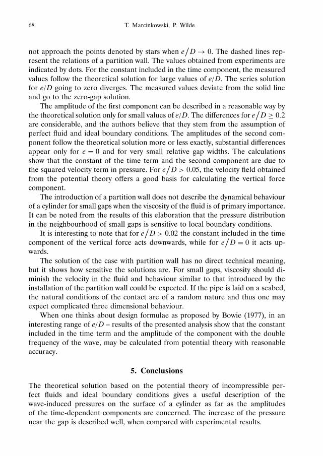
integration as presented in the introduction.In Fig. 9 the amplitudes of components of vertical forces are plotted versus
the relative gap e/ D (D – diameter of the cylinder). The solid lines represent thesolution with a finite gap width. The points shown by stars correspond to the solu-tion e
Ž
D D 0. It may be seen that the solutions represented by the solid lines do

Application of Potential Theory in Calculating Wave-Induced Vertical Forces : : : 67
Fig. 9. Amplitudes of component as function of bottom clearance
68 T. Marcinkowski, P. Wilde
not approach the points denoted by stars when eŽ
D ! 0. The dashed lines rep-resent the relations of a partition wall. The values obtained from experiments areindicated by dots. For the constant included in the time component, the measuredvalues follow the theoretical solution for large values of e/ D. The series solutionfor e/ D going to zero diverges. The measured values deviate from the solid lineand go to the zero-gap solution.
The amplitude of the first component can be described in a reasonable way bythe theoretical solution only for small values of e/ D. The differences for e
Ž
D ½ 0:2are considerable, and the authors believe that they stem from the assumption ofperfect fluid and ideal boundary conditions. The amplitudes of the second com-ponent follow the theoretical solution more or less exactly, substantial differencesappear only for e D 0 and for very small relative gap widths. The calculationsshow that the constant of the time term and the second component are due tothe squared velocity term in pressure. For e
Ž
D > 0:05, the velocity field obtainedfrom the potential theory offers a good basis for calculating the vertical forcecomponent.
The introduction of a partition wall does not describe the dynamical behaviourof a cylinder for small gaps when the viscosity of the fluid is of primary importance.It can be noted from the results of this elaboration that the pressure distributionin the neighbourhood of small gaps is sensitive to local boundary conditions.
It is interesting to note that for eŽ
D > 0:02 the constant included in the timecomponent of the vertical force acts downwards, while for e
Ž
D D 0 it acts up-wards.
The solution of the case with partition wall has no direct technical meaning,but it shows how sensitive the solutions are. For small gaps, viscosity should di-minish the velocity in the fluid and behaviour similar to that introduced by theinstallation of the partition wall could be expected. If the pipe is laid on a seabed,the natural conditions of the contact are of a random nature and thus one mayexpect complicated three dimensional behaviour.
When one thinks about design formulae as proposed by Bowie (1977), in aninteresting range of e/ D – results of the presented analysis show that the constantincluded in the time term and the amplitude of the component with the doublefrequency of the wave, may be calculated from potential theory with reasonableaccuracy.
5. Conclusions
The theoretical solution based on the potential theory of incompressible per-fect fluids and ideal boundary conditions gives a useful description of thewave-induced pressures on the surface of a cylinder as far as the amplitudesof the time-dependent components are concerned. The increase of the pressurenear the gap is described well, when compared with experimental results.

Application of Potential Theory in Calculating Wave-Induced Vertical Forces : : : 69
The pressure distribution near small gaps is very sensitive to local boundaryconditions. The solution for a finite gap does not go uniformly to the limiting casewhen there is no gap at the bottom.
The phase shifts with respect to the waves are poorly described by the potentialtheory. The suggestion is that the dissipation of energy due to viscosity and vortexshedding, which cannot be described by the applied potential theory, plays animportant role.
The resultant horizontal force component is not as sensitive to the local condi-tions near the gap as the vertical force component, and a solution for finite gapsgoes uniformly over to the limiting case of no gap. The potential theory givesa good estimate of the influence of the e/ D parameter on the inertia term in theMorison formula.
The squared velocity term in the pressures is important for the resultant ver-tical forces. The potential theory solution gives a good estimate of the amplitudecomponents due to this term. The phase shift must be taken from experiments,and it is plausible that it may be estimated when viscous effects are considered.
References
Bowie L. G. (1977), Forces Exerted by Waves on a Pipeline at or Near the Ocean Bottom, Technicalpaper No. 77–11, US Army, Corps of Engineers, Coastal Engineering Research Centr.
Carpenter L. H. (1958), On the motion of two cylinders in an ideal fluid, Journal of Research ofthe National Bureau of Standards, Vol. 61, No. 2, 83–87.
Chakrabarti S. K. (1987), Hydrodynamics of Offshore Structures, Computational Mechanics Pub-lications, Springer Verlag, Berlin, Heidelberg.
Moon P., Spencer D. E. (1971), Field Theory Handbook, Springer Verlag, Berlin, Heidelberg, NewYork.
Muller W. (1928), Matematische Stromungslehre, Springer Verlag, Berlin.
Sarpkaya T., Isaacson M. (1981), Mechanics of Wave Forces on Offshore Structures, Van NostrandReinhold Company, New York.
Sumer B. M., Fredsøe J. (1997), Hydrodynamics around Cylindrical Structures, Advanced Serieson Ocean Engineering, Vol. 12, World Scientific.
Wright J. C. Yamamoto T. (1979), Wave forces on cylinders near plane boundaries, Journal ofWaterways, Port, Coastal and Ocean Division ASCE, Vol. 101, No. WW 1, 1–13.
Yamamoto T., Nath J. H., Slotta L. S. (1974), Wave forces on cylinders near plane boundary,Journal of Waterways, Port, Coastal and Ocean Division ASCE, Vol. 100, No. 4, 345–359.