application of rapid prototyping and wire arc spray to · pdf filewire arc spray (was) is a...
TRANSCRIPT
NASA / TM--2000-210558
Application of Rapid Prototyping
and Wire Arc Spray to the Fabrication
of Injection Mold Tools(MSFC Center Director's Discretionary Fund Final Report,
Project No. 99-05)
K.G. Cooper
Marshall Space Flight Center, Marshall Space Flight Center, Alabama
National Aeronautics and
Space Administration
Marshall Space Flight Center • MSFC, Alabama 35812
A ugust 2000
https://ntrs.nasa.gov/search.jsp?R=20000109872 2018-05-04T10:43:52+00:00Z
Acknowledgments
The author would like to thank the t_)llowing people for participation and support in this project:
Ricky Johnson, Boeing/MSFC
Heather Miller, Boeing/MSFC
Jim Bond, BoeinJMSFCJoe Paxton, UAH Research Institute
Pat Salvail, Illinois Institute of Technology Research Institute/MSFCRon Lee, MSFC
Danny Jordan, MSFC
Available fi'om:
NASA Center fi)r AeroSpace lnlkwmation7121 Standard Drive
Hanover. MD 21076-1320
(301) 621-0390
National Technical Information Service
5285 Port Royal Road
Springfield, VA 22161(7031 487-4650
ii
TABLE OF CONTENTS
1. BACKGROUND .........................................................................................................................
1.1 Z402 Three-Dimensional Printing Process ..........................................................................
1.2 Thermojet Process ................................................................................................................
2. THE STUDY ...............................................................................................................................
2.1 Design and Rapid Prototyping .............................................................................................
2.2 Metal Spraying of Tool Halves .............................................................................................
2.3 Pattern Removal and Backfilling ..........................................................................................
2.4 Injection Molding Trials .......................................................................................................
3. SUMMARY ................................................................................................................................
3
5
6
7
11
iii

LIST OF FIGURES
,
2.
3.
4.
5.
6.
7.
8.
9.
10.
Z402 three-dimensional printer .........................................................................................
Thermojet RP machine ......................................................................................................
Baseline injection tool design ............................................................................................
Wax thermojet patterns ......................................................................................................
Metal-sprayed wax pattern ................................................................................................
Metal tool shell after wax removal ....................................................................................
Finished metal-faced tool halves .......................................................................................
First tool failure after removal ...........................................................................................
First tool failure (other half) ..............................................................................................
Plastic parts injected into metal-sprayed tooling sets ........................................................
,-)
2
4
4
5
6

LIST OF ACRONYMS
CAD
MSFC
PEC
RP
UAH
WAS
computer-aided design
Marshall Space Flight Center
Productivity Enhancement Complex
rapid prototyping
University of Alabama in Huntsville
wire arc spray
vii

TECHNICAL MEMORANDUM
APPLICATION OF RAPID PROTOTYPING AND WIRE ARC SPRAY
TO THE FABRICATION OF INJECTION MOLD TOOLS
(MSFC Center Director's Discretionary Fund Final Report, Project No. 99-05)
1. BACKGROUND
Rapid prototyping (RP) is a layer-by-layer-based additive manufacturing process for constructing
three-dimensional representations of a computer design from a wax, plastic, or similar material. Wire arc
spray (WAS) is a metal spray forming technique that deposits thin layers of metal onto a substrate or
pattern. Marshall Space Flight Center (MSFC) currently has both capabilities in-house, and this project
proposed merging the two processes into an innovative manufacturing technique.
The concept of spray metal forming onto RP patterns has been demonstrated at MSFC using
a low-temperature metal alloy and wood- or plastic-based patterns. Unfortunately, the pattern can then
be difficult to remove from the metal shell, especially on parts with complex features. This project used
a water-soluble, starch-based material, which is currently the build material used in the Z402 three-
dimensional printing process located on site, as well as a low-temperature, wax-polymer material used
in the on-site thermojet machine.
1.1 Z402 Three-Dimensional Printing Process
The Z402 three-dimensional printing process is an ink jet-based RP technology that builds starch
patterns directly from computer-aided design (CAD) data. The process builds the part from the bottom
upward by adding thin layers of powder, then printing a binder solution in the shape of the current cross
section of the part. The resulting object is a soft, water-soluble material that typically would be infiltrated
with cyanoacrylate or paraffin wax to be used as a concept model or casting pattern. The Z402 three-
dimensional printer is shown in figure 1.
1.2 Thermojet Process
The thermojet process is also based on ink jet technology; however, instead of powders and
binder, this process simply prints layers of hot wax. Each layer is printed to match a cross section of the
part, from the bottom upward, until a solid wax pattern is created. These parts are typically used for
concept models or investment casting patterns. The thermojet is shown in figure 2.
This proposal was for a 1-yr application study, in which intermediate injection tools would be
fabricated with RP and WAS metal forming. It provides an indepth development effort between NASA,
Boeing, and the University of Alabama in Huntsville (UAH), utilizing multiple materials to provide
optimum performance for an injection tool.
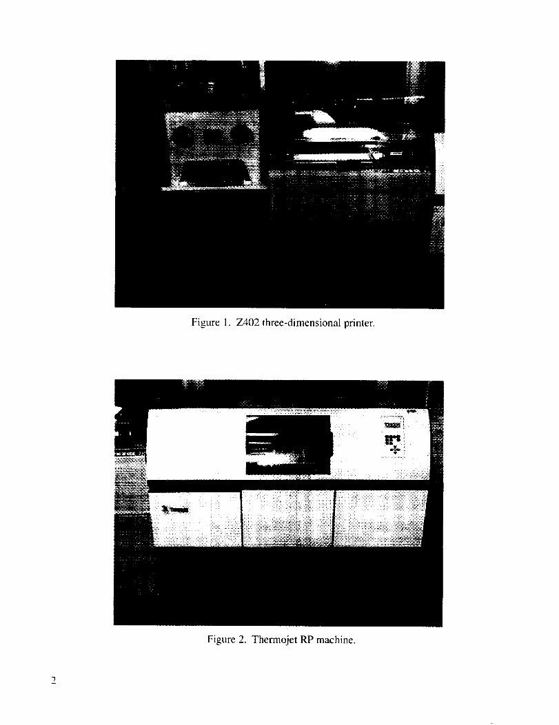
Figure 1. Z402three-dimensionalprinter.
Figure2. ThermojetRPmachine.
2. THE STUDY
2.1 Design and Rapid Prototyping
The MSFC Rapid Prototyping facility in the Productivity Enhancement Complex (PEC) created
six sets of tooling patterns with the water-soluble and wax pattern materials. This required software
manipulation of the CAD models to convert them into tooling form, as well as the actual rapid fabrica-
tion of the components on the Z402 three-dimensional printer and thermojet machine. The geometry
chosen was a standard injection mold tool used as a baseline in the RP industry for new tool fabrication
techniques. The part combines thin walls and complex fin arrangements suggestive of typical injection-
molded components. Figure 3 demonstrates the chosen model for this project.
One modification was made to the design for the injection port available on the mold press at
UAH. Due to the high clamping pressure (8 tons), it was recommended to have the mold halves join
parallel to the press, or horizontally. In order to achieve this, the injection port was arranged to enter
the top of the part, perpendicular to the original configuration.
The time required to build a two-piece mold on the Z402 machine was found to be =2 hr. These
patterns had a rough surface finish and were also very soft in the as-processed form. The surface quality
of the molds was not acceptable for an injection molding application.
The thermojet wax patterns were built in =3 hr, with an additional cooling and postprocessing
time. The surface finish of these patterns was very smooth and of high quality. Because of this, the
remainder of the study focused solely on the thermojet patterns as opposed to the Z402 parts. In addi-
tion, the thermojet patterns were much more rigid than the Z402 soft patterns; hence, less careful han-
dling was required for a successful run.
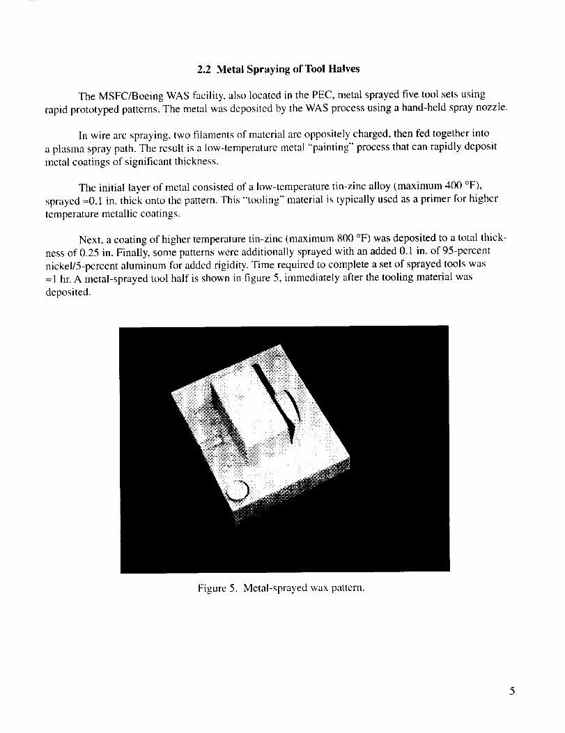
Slight preparation for the injection port was required on all tool halves. A small metal tube was
inserted upright into the wax pattern by heating it slightly and holding it in place with a pin. This would
allow for metal to be sprayed around it; hence, upon removal of the pin, a ready-made injection port was
created. A set of the final wax mold is shown in figure 4.
3
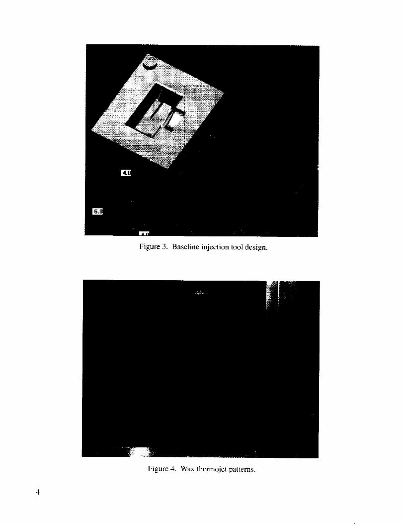
Figure3. Baselineinjectiontooldesign.
Figure4. Waxthermojetpatterns.
4
2.2 Metal Spraying of Tool Halves
The MSFC/Boeing WAS facility, also located in the PEC, metal sprayed five tool sets using
rapid prototyped patterns. The metal was deposited by the WAS process using a hand-held spray nozzle.
In wire arc spraying, two filaments of material are oppositely charged, then fed together into
a plasma spray path. The result is a low-temperature metal "painting" process that can rapidly deposit
metal coatings of significant thickness.
The initial layer of metal consisted of a low-temperature tin-zinc alloy (maximum 400 °F),
sprayed --0.1 in. thick onto the pattern. This "tooling" material is typically used as a primer for higher
temperature metallic coatings.
Next, a coating of higher temperature tin-zinc (maximum 800 °F) was deposited to a total thick-
ness of 0.25 in. Finally, some patterns were additionally sprayed with an added 0.1 in. of 95-percent
nickel/5-percent aluminum for added rigidity. Time required to complete a set of sprayed tools was
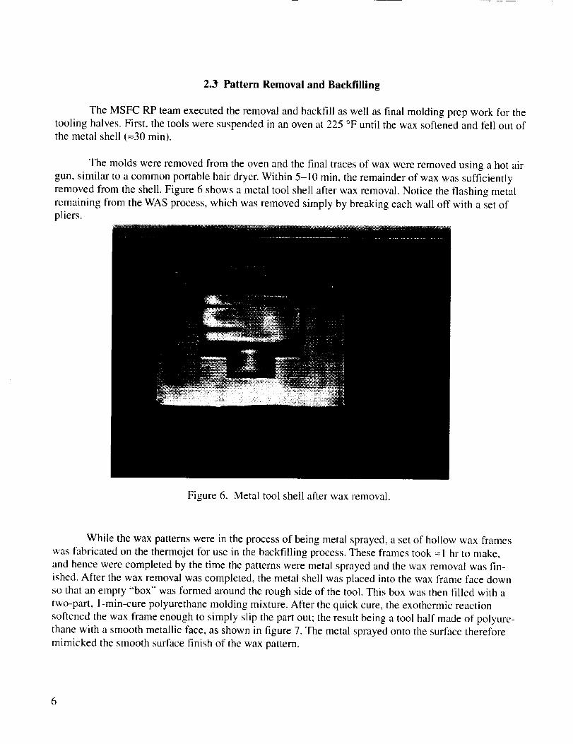
1 hr. A metal-sprayed tool half is shown in figure 5, immediately after the tooling material was
deposited.
Figure 5. Metal-sprayed wax pattern.
5
2.3 Pattern Removal and Backfilling
The MSFC RP team executed the removal and backfill as well as final molding prep work for the
tooling halves. First, the tools were suspended in an oven at 225 °F until the wax softened and fell out of
the metal shell (=30 min).
The molds were removed from the oven and the final traces of wax were removed using a hot air
gun, similar to a common portable hair dryer. Within 5-10 min, the remainder of wax was sufficiently
removed from the shell. Figure 6 shows a metal tool shell after wax removal. Notice the flashing metal
remaining from the WAS process, which was removed simply by breaking each wall off with a set ofpliers.
Figure 6. Metal tool shell after wax removal.
While the wax patterns were in the process of being metal sprayed, a set of hollow wax frames
was fabricated on the thermojet for use in the backfilling process. These frames took = 1 hr to make,
and hence were completed by the time the patterns were metal sprayed and the wax removal was fin-
ished. After the wax removal was completed, the metal shell was placed into the wax frame face down
so that an empty "box" was formed around the rough side of the tool. This box was then filled with a
two-part, I-rain-cure polyurethane molding mixture. After the quick cure, the exothermic reaction
softened the wax frame enough to simply slip the part out; the result being a tool half made of polyure-
thane with a smooth metallic face, as shown in figure 7. The metal sprayed onto the surface therefore
mimicked the smooth surface finish of the wax pattern.
6
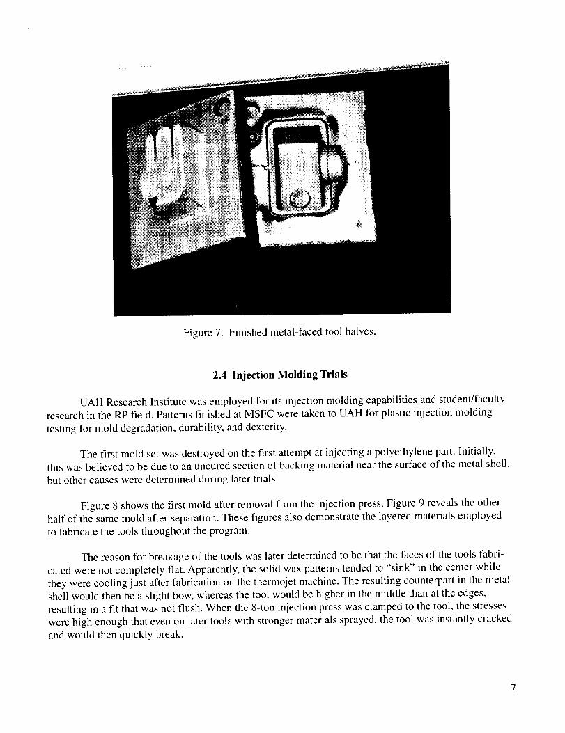
Figure7. Finishedmetal-facedtool halves.
2.4 Injection Molding Trials
UAH Research Institute was employed for its injection molding capabilities and student/faculty
research in the RP field. Patterns finished at MSFC were taken to UAH for plastic injection molding
testing for mold degradation, durability, and dexterity.
The first mold set was destroyed on the first attempt at injecting a polyethylene part. Initially,
this was believed to be due to an uncured section of backing material near the surface of the metal shell,
but other causes were determined during later trials.
Figure 8 shows the first mold after removal from the injection press. Figure 9 reveals the other
half of the same mold after separation. These figures also demonstrate the layered materials employed
to fabricate the tools throughout the program.
The reason for breakage of the tools was later determined to be that the faces of the tools fabri-
cated were not completely flat. Apparently, the solid wax patterns tended to "sink" in the center while
they were cooling just after fabrication on the therrnojet machine. The resulting counterpart in the metal
shell would then be a slight bow, whereas the tool would be higher in the middle than at the edges,
resulting in a fit that was not flush. When the 8-ton injection press was clamped to the tool, the stresses
were high enough that even on later tools with stronger materials sprayed, the tool was instantly cracked
and would then quickly break.
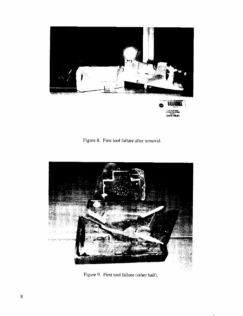
Figure 8. First tool failure after removal.
Figure 9. First tool failure (other half).

3. SUMMARY
Although this project ran into some difficulty, some important lessons were learned that still
might be applied to injection mold tooling and other applications.
It was determined that tool halves of a surface quality representative of the rapid prototyped
pattern could be fabricated quickly and inexpensively via this process. Until the RP techniques can
hold a smoother surface finish and tighter tolerance, the metal spray and fill technique may be used on
machined wax patterns to achieve the necessary dimensional requirements. This approach would still
be more cost effective than machining steel or aluminum tools for only short production runs.
Another application could use the RP/WAS processing tools for less stressful injection molding
or pour molding applications; i.e., investment casting wax pattern injection. Further research and testingwill continue in these and other related areas at MSFC and other institutions.
11
REPORT DOCUMENTA'f'ION PAGE FormApprovedOMB No. 0704-0188
PubhC repoding burderl lot this collection of informalion is estimated to average I hour per response, including the time for reviewing _nstructions, searching existing data sources,
gathering and maintaining the data needed, and completing and reviewing the collection ol information, Send comments regarding this burden estimate or any othe( aspect ol this
colleclion of informalion, including suggestions for reducing this burden, to Washington Headquarters Senaces, Directorate for Inforrnalion Operation and Reports. 1215 Jefferson
Davis Highway, Suite 1204. Arlington, VA 22202 4302, and to the Office of Management and Budgel, Papen_,ork Reduction Project (0704-0188), Washington, DC 20503
1. AGENCY USE ONLY (Leave Blank) 2. REPORT DATE 3. REPORT TYPE AND DATES COVERED
August 2000 Technical Memorandum4. TITLE AND SUBTITLE 5. FUNDING NUMBERS
Application of Rapid Prototyping and Wire Arc Spray
to the Fabrication of Injection Mold Tools(MSFC Center Director's Discretionary Fund Final Report, Project No. 99-05)
6. AUTHORS
K.G. Cooper
7. PERFORMINGORGANIZATIONNAMES(S)ANDADDRESS(ES)
George C. Marshall Space Flight Center
Marshall Space Flight Center, AL 35812
9. SPONSORING/MONITORINGAGENCYNAME(S)ANDADDRESS(ES)
National Aeronautics and Space Administration
Washington, DC 20546-0001
8. PERFORMING ORGANIZATION
REPORT NUMBER
M-993
10. SPONSORING/MONITORING
AGENCY REPORT NUMBER
NASA/TM--2000-210558
11. SUPPLEMENTARY NOTES
Prepared by the Materials, Processes, and Manufacturing Department, Engineering Directorate
12a. DISTRIBUTION/AVAILABILITY STATEMENT
Unclassified-Unlimited
Subject Category 37Nonstandard Distribution
12b. DISTRIBUTION CODE
13. ABSTRACT (Maximum 200 words)
Rapid prototyping (RP) is a layer-by-layer-based additive manufacturing process for constructing
three-dimensional representations of a computer design from a wax, plastic, or similar material.
Wire arc spray (WAS) is a metal spray forming technique, which deposits thin layers of metal
onto a substrate or pattern. Marshall Space Flight Center currently has both capabilities in-house,
and this project proposed merging the two processes into an innovative manufacturing technique,in which intermediate injection molding tool halves were to be fabricated with RP and WAS
metal forming.
14. SUBJECT TERMS
manufacturing, injection molding, rapid prototyping, spray metal tooling,
wire arc spray
17. SECURITY CLASSIFICATION
OF REPORT
UnclassifiedNSN7_40-Of-280-SSO0
18. SECURITY CLASSIFICATION
OF THIS PAGE
Unclassified
15. NUMBER OF PAGES
2O16. PRICE CODE
A0319. SECURITY CLASSIFICATION 20. LIMITATION OF ABSTRACT
OF ABSTRACT
Unclassified UnlimitedStandard Form 298 (Rev 2-89)
PreScribed by ANSI sir 239-18
298-102
A potential fix for the "sink" problem is to build the wax part hollow so as not to create such a
dense mass. The hollow part would then be filled from the back with polyurethane prior to depositing a
metal shell on the front. Attempts were made to spray the metal shell onto the hollow wax patterns (with
no fill); however, the heat and stresses associated with the WAS were too much for the pattern to stand
up to.
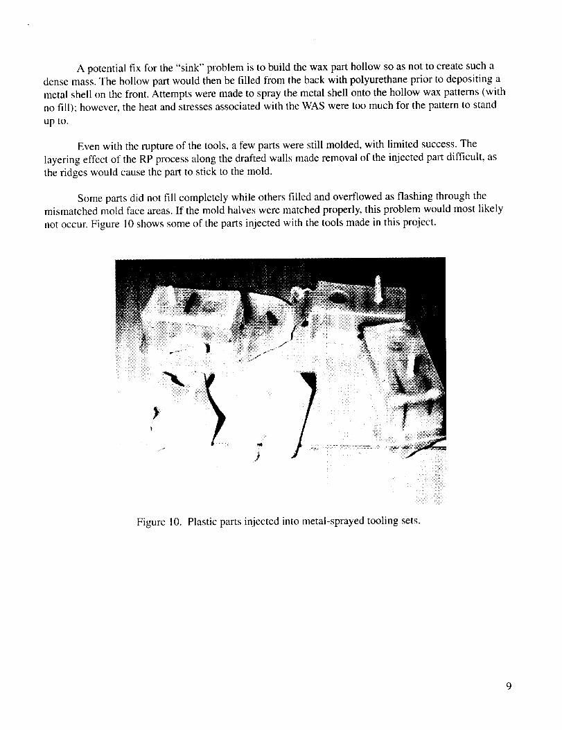
Even with the rupture of the tools, a few parts were still molded, with limited success. The
layering effect of the RP process along the drafted walls made removal of the injected part difficult, as
the ridges would cause the part to stick to the mold.
Some parts did not fill completely while others filled and overflowed as flashing through the
mismatched mold face areas. If the mold halves were matched properly, this problem would most likely
not occur. Figure 10 shows some of the parts injected with the tools made in this project.
Figure 10. Plastic parts injected into metal-sprayed tooling sets.
9


National Aeronautics andSpaceAdministrationAD33George C. Marshall SpaceFlight CenterMarshall SpaceFlight Center,Alabama35812