application of the self-heat recuperation technology to ... · abstract—an innovative self-heat...
TRANSCRIPT
Abstract—An innovative self-heat recuperation technology,
in which not only latent heat but also sensible heat is circulated
in the thermal process, was studied and applied to the
deisobutanizer column. To determine the amount of energy
required for this technology, ASPEN HYSYS was used.
According to the simulation of the proposed sequence, the
condenser duty and reboiler duty were saved up to 73.43 and
83.48%, respectively as compared to conventional column.
Index Terms—Distillation process, self-heat recuperation,
deisobutanizer.
I. INTRODUCTION
Separations by distillation columns account for the largest
fraction of energy used in industry, making them a major
concern for sustainable development in industrially
developed countries. Distillation is the most widely used
separation process in industry, and its large-scale equipment
makes it one of the most capital-intensive industrial
processes. With global industrial growth, distillation is
increasing in both variety and size of applications. Hence
distillation systems are required that are sustainable and
economically feasible, i.e. industrially viable [1]-[3].
In the distillation process, heat is supplied at a feed heater
and a reboiler, and an overhead stream is cooled at a
condenser. Almost all of the supplied heat at the reboiler in
the conventional distillation process is discarded in the
overhead condenser [4]. Heat pumps in distillation allow the
heat of condensation released at the condenser to be used for
evaporation in the reboiler [5]. This is an economic way to
conserve energy when the temperature difference between
the overhead and the bottom of the column is small and the
heat load is high. Heat pumps can also be used in grass-roots
or retrofitting design because they are easy to introduce and
plant operation is usually simpler than heat integration
[6]-[10]. However, the high capital expenditure required for
compressors make them industrially viable only for
high-capacity, end-of-train (practically binary) separations of
substances with close boiling points, which require minimal
compressor/compression costs. This is the case mainly in the
separation of light hydrocarbons, such as C2, C3 and C4
components, where the adiabatic exponents of the substances
are large enough to enable significant temperature increases
with relatively low compression effort [1], [4], [11].
Manuscript received September 15, 2012; revised November 27, 2012.
This work was supported by research funding from School of Chemical
Engineering, Yeungnam University
Moonyong Lee is with the School of Chemical Engineering, Yeungnam
University (e-mail: [email protected]).
Furthermore, in heat pump, only the heat recovery duty to the
reboiler in the distillation column is considered, but the heat
during preheating is not or is less recognized [4].
Self-heat recuperation technology facilitates recirculation
of not only latent heat but also sensible heat in a process, and
helps to reduce the energy consumption of the process by
using compressors and self-heat exchangers based on exergy
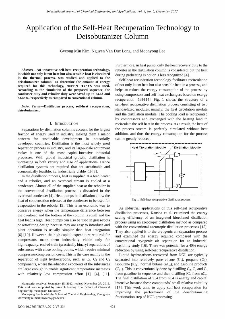
recuperation [13]-[14]. Fig. 1 shows the structure of a
self-heat recuperative distillation process consisting of two
standardized modules, namely, the heat circulation module
and the distillation module. The cooling load is recuperated
by compressors and exchanged with the heating load to
recirculate the self heat in the process. As a result, the heat of
the process stream is perfectly circulated without heat
addition, and thus the energy consumption for the process
can be greatly reduced.
Fig. 1. Self-heat recuperative distillation process.
As industrial applications of this self-heat recuperative
distillation processes, Kansha et al. examined the energy
saving efficiency of an integrated bioethanol distillation
process using an azeotropic distillation method as compared
with the conventional azeotropic distillation processes [15].
They also applied it to the cryogenic air separation process
and examined the energy required compared with the
conventional cryogenic air separation for an industrial
feasibility study [16]. There was potential for a 40% energy
reduction by using self-heat recuperative distillation.
Liquid hydrocarbons recovered from NGL are typically
separated into relatively pure ethane (C2), propane (C3),
isobutane (iC4), normal butane (nC4), and gasoline products
(C5+). This is conventionally done by distilling C2, C3 and C4
from gasoline in sequence and then distilling iC4 from nC4.
The final distillation of iC4 from nC4 is energy and capital
intensive because these compounds’ small relative volatility
[17]. This work aims to apply self-heat recuperation for
improving the performance of the deisobutanizing
fractionation step of NGL processing.
Application of the Self-Heat Recuperation Technology to
Deisobutanizer Column
Gyeong Min Kim, Nguyen Van Duc Long, and Moonyong Lee
International Journal of Chemical Engineering and Applications, Vol. 3, No. 6, December 2012
424DOI: 10.7763/IJCEA.2012.V3.234

II. CONVENTIONAL DISTILLATION COLUMN -
DEISOBUTANIZER
A deisobutanizer, possessing 92 theoretical trays, was
designed and operated for 6.5 bar (Fig. 2) as commercial
isobutane can be condensed with cooling water at this
pressure [18]-[20]. Modeled columns' maximum flooding
was determined using a rating mode simulated using the
columns' internal specifications such as type of trays, column
diameter, tray spacing, and number of passes. Simulations
were performed using the simulator ASPEN HYSYS V7.3.
The Peng-Robinson equation of state was used to predict the
vapor-liquid equilibria of these simulations [21]. The base
case simulation model shows that the energy consumption of
deisobutanizer was 7271 KW.
All columns were designed with loads of ca. 85% of the
flooding point load to prevent flooding. Furthermore, the
pressure of the outlet compressor was adjusted to obtain a
minimum approach in the heat exchanger of 10 °C.
Fig. 2. Simplified flow sheet illustrating the conventional column –
deisobutanizer.
III. SELF-HEAT RECUPERATION
In the vapor recompression technology, a well known heat
recovery technology, the vapor is compressed to a higher
pressure and then the pressurized vapor provides a heating
effect when condensing. However, such technology utilizes
only the latent heat but not the sensible heat [4]. In contrast,
self-heat recuperation technology utilizes not only latent heat
but also the sensible heat in the process by using a
compressor. In self-heat recuperation technology, the heat of
the streams is recuperated by using compressors and the
recuperated heat of the pressurized stream is supplied to the
cold stream by heat exchange.
In the distillation process for the heavy chemical industrial
field, it can be said that the two types of self-heat recuperative
processes were integrated [4]. One is the self-heat
recuperation distillation in which the partial heat of the
overhead vapor (the reflux stream) is recuperated and the
recuperated heat is supplied to the reboiler. The other is the
heat circulation system for feed heating, which leads to the
remaining partial heat of the overhead vapor (the overhead
product stream) being recuperated and being supplied to the
feed heater.
Fig. 3. Effect of feed split ratio on the reboiler duty.
The compressor treated all overhead vapor and the
compressed vapor was divided into the reboiler and the feed
heater. The feed stream was divided into two parallel streams,
which were exchanged with the overhead and the bottom
product streams to maximize the heat recovery duty.
Adjustment of the feed split ratio in important in the
maximization the heat recovery duty and minimization the
compressor power (Fig. 3). A simplified flow sheet outlining
the self-heat recuperative distillation process is shown in Fig.
4. Note that the split is defined as the ratio between the flow,
which is heat exchanged with the bottom product stream, to
the total flow (m2/m). A feed split ratio of 0.72 is optimal,
reducing condenser duty, reboiler duty, and operating costs
by 73.43, 83.48, and 53.49%, respectively as compared to
conventional sequence. The simulation results show that
when the feed is supplied the heat, the top vapor stream is
increased, i.e. more heat can be recuperated.
Besides, the boil-up stream is decreased, which cause the
column diameter decreases from 2.4 to 2.3 m. Thus, this
sequence can be utilized not only in grass-root case but also
in retrofit case, which is considered significantly nowadays
by processing industry. This is a promising technology when
problem is associated to binary mixture separation or that
column should not integrate with other columns in sequence.
From the existing column, new heat exchangers and
compressor are installed while the number of trays and
diameter of column are fixed. More pipe work is also needed
for the equipment link. From a technique point of view, those
works can be accomplished in easy manner and short
modification time.
Fig. 4. Simplified flow sheet illustrating the self-heat recuperative distillation
process.
International Journal of Chemical Engineering and Applications, Vol. 3, No. 6, December 2012
425
IV. CONCLUSIONS
In this paper, the self-heat recuperative distillation process
for industrial application was proposed. The results show that
the advanced process with self-heat recuperation technology
was able to reduce the energy consumption significantly by
using the recuperated heat of the overhead vapor. This work
also pointed out that those sequences are promising
technology in retrofit project, which can be accomplished in
an easy manner and short modification time.
ACKNOWLEDGEMENTS
This research was supported by a grant from the Gas Plant
R&D Center funded by the Ministry of Land, Transportation
and Maritime Affairs (MLTM) of the Korean government.
REFERENCES
[1] I. Dejanović, L. Matijašević, and Ž. Olujić, “Dividing wall column-a
breakthrough towards sustainable distilling,” Chem. Eng. Process, vol.
49, pp. 559-580, 2010.
[3] Ž. Olujić, M. Jödecke, A. Shilkin, G. Schuch, and B. Kaibel,
“Equipment improvement trends in distillation,” Chem. Eng. Process,
vol. 48, pp. 1089-1104, 2009.
[4] K. Matsuda, K. Kawazuishi, Y. Kansha, C. Fushimi, M. Nagao, H.
Kunikiyo, F. Masuda, and A. Tsutsumi, “Advanced energy saving in
distillation process with self-heat recuperation technology,” Energy,
vol. 36, pp. 4640-4645, 2011.
[5] D. Bruisma and S. Spoelstra, “Heat pumps in distillation,” Distillation
Absorption. 2010.
[6] N. Asprion and G. Kaibel, “Dividing wall columns: Fundamentals and
recent advances,” Chem. Eng. Process, vol. 49, pp. 139-146, 2010.
[7] O. Annakou and P. Mizsey, “Rigorous investigation of heat pump
assisted distillation,” Heat Recovery Systems and CHP, vol. 15, pp.
241-247, 1995.
[8] F. Moser and H. Schnitzer, “Heat pumps in industry,” Elsevier,
Amsterdam, 1985.
[9] S. Ranade and Y. Chao, “Industrial heat pumps: Where and when?”
Hydrocarbon Processing, pp. 71-73, 1990.
[10] P. Mizsey and Z. Fonyo, “Energy integrated distillation system design
enhanced by heat pumping,” Distillation and Absorption, IChemE., pp.
1369-1376, 1992.
[11] J. Stichlmair, “Distillation and Rectification,” in Ullmann’s
Encyclopedia of Industrial Chemistry - Fifth Edition, vol. B3, pp.
4.1-4.9, 1988.
[12] J. G. Stichlmair and J. R. Fair, “Distillation-principles and practices,”
Wiley-VCH, New York, 1998.
[13] Y. Kansha, N. Tsuru, K. Sato, C. Fushimi, and A. Tsutsumi, “Self-heat
recuperation technology for energy saving in chemical processes,” Ind.
Eng. Chem. Res., vol. 48, no. 16, pp.7682-7686, 2009.
[14] Y. Kansha, A. Kishimoto, M. Aziz, and A. Tsutsumi, “Heat
Exchangers: Basics design applications, Jovan Mitrovic, chapter 3,”
Self-Heat Recuperation: Theory and Applications, 2012.
[15] Y. Kansha, N. Tsuru, C. Fushimi, and A. Tsutsumi, “New design
methodology based on self-heat recuperation for production by
azeotropic distillation,” Energy and Fuels, vol. 24, no. 11, pp.
6099-6102, 2010.
[16] Y. Kansha, N. Tsuru, C. Fushimi, K. Shimogawara, and A. Tsutsumi,
“An innovative modularity of heat circulation for fractional
distillation,” Chemical Engineering Science, vol. 65, no. 1, pp. 330-334,
2010.
[17] D. B. Manley, U. S. patent 8, vol. 806, no. 339, 1998.
[18] K. A. Amminudin and R. Smith, “Design and optimization of fully
thermally coupled distillation columns. Part 2: Application of dividing
wall columns in retrofit,” Trans. IChemE, vol. 79, pp. 716-724, 2001.
[19] K. T. Klemola and J. K. Ilme, “Distillation efficiencies of an
industrial-scale i-butane/n-butane fractionator,” Ind. Eng. Chem. Res.,
vol. 35, pp. 4579-4586, 1996.
[20] N. V. D. Long and M. Y. Lee, “Design and optimization of a dividing
wall column by factorial design,” Korean J. Chem. Eng., vol. 29, pp.
567-573, 2012.
International Journal of Chemical Engineering and Applications, Vol. 3, No. 6, December 2012
426
[2] J. L. Humphrey and G. E. Keller, Separation Process Technology,
McGraw-Hill, New York, 1997.
[21] Aspen HYSYS Thermodynamics COM Interface, Aspen technology,
version number vol. 7.1, 2009.