the geocollect geothermal energy absorber module … · due to the discontinuous mode of operation...
TRANSCRIPT

The GeoCollect
Geothermal Energy Absorber Module
Energy-efficient Heating
with
Nature's Inexhaustible Energy
Heating in the winter
Cooling in the summer

THE ABSORBER PRINCIPLE
GeoCollect geothermal energy modules collect valuable energy from the soil. A properly dimensioned
module will guarantee a steady regeneration of the ground within its area of absorption.
GeoCollect geothermal energy modules are an effective and cost-efficient alternative to geothermal
probes. In contrast to conventional surface collectors, this system needs far less land.
Operation - Extraction capacity (see also illustration on the following page):
GeoCollect absorbers achieve their highly efficient extraction rate by their excellent surface design and
a low and a highly turbulent flow (low-flow principle).
Their vertical installation allows the exploitation of a large cubature of ground (approx. 0.5 m
horizontally and 0.4 m vertically)
This setup leads, at a distance of 0.7 m between the individual absorbers, to an extremely small
footprint at a ground extraction capacity of 142.61 W/m².
The calculated basis of 99.83 W per module is in principle applicable for all ground conditions, with the
exception of gravel (not aquiferous).
Due to the discontinuous mode of operation of the heat pump the ground will always have enough time
for recuperation, hence will always provide enough heat (see table on the following page).
Please observe the regulations according to DIN 4124 (10.02)!

THE TECHNOLOGICAL BASICS The determination of the performance values was made upon the average ground conditions in Germany:
Quelle:
Period September / October
Temperature prior to the operation of the heat pump
Temperature after thirty minutes of operation
Temperature after one hour of operation
Temperature after one hour of standstill
Temperature after two hours of standstill
WQA (Output from the heat pump) 12 °C 8 °C 7 °C 10 °C 11 °C
WQE (Input to the heat pump) 12 °C 11 °C 10 °C 10 °C 11 °C
Period January/ February
Temperature prior of operation
Temperature after thirty minutes of operation
Temperature after one hour of operation
Temperature after one hour stand still
Temperature after two hours of standstill
WQA (Output from the heat pump) 3 °C -2 °C -4 °C 2,1 °C 2,6 °C
WQE (Input to the heat pump) 3 °C 1 °C -1 °C 2,1 °C 2,6 °C
Typischer Temperaturverlauf zu Beginn und zur Spitze der Heizperiode
This table demonstrates how the temperature stored in the ground continually leads to energetically
valuable phase transitions at the outsides of the absorber surfaces, in a way that the system almost
entirely regenerates on the level of January/February even after a long winter (e.g. to April) during the
standstill periods of the heat pump.
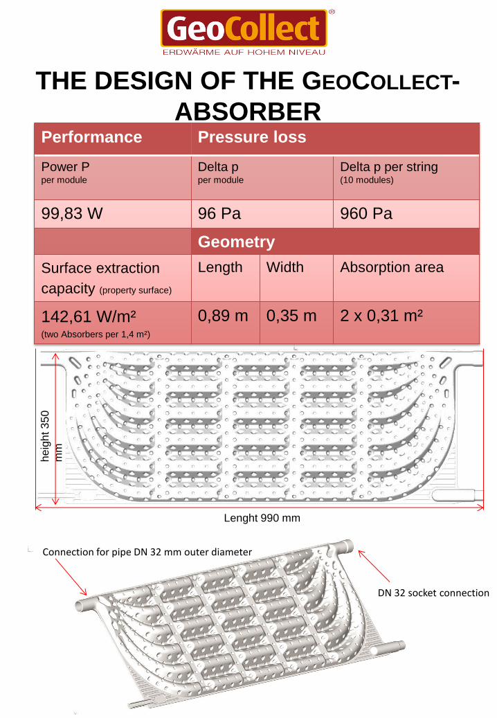
THE DESIGN OF THE GEOCOLLECT-
ABSORBER Performance Pressure loss
Power P per module
Delta p per module
Delta p per string (10 modules)
99,83 W 96 Pa 960 Pa
Geometry
Surface extraction
capacity (property surface)
Length Width Absorption area
142,61 W/m² (two Absorbers per 1,4 m²)
0,89 m 0,35 m 2 x 0,31 m²
Lenght 990 mm
he
igh
t 3
50
mm
Connection for pipe DN 32 mm outer diameter
DN 32 socket connection

TECHNICAL SPECIFICATIONS
5
Geprüft und überwacht
durch:
Entwicklungspartner der WätaS GmbH:
Material: PP Technische Daten je Modul:
Maße: (L/B/H) 1080x340x40 mm
Material: Polypropylen (PP)
Gewicht: 1648g
Kälteleistung: 83,33 Watt
Max. Strang: 12 Module
Einbringung: senkrecht stehend
Füllmenge: 1,59 Liter
Properties/ Metrics/ Operational parameters Prüfverfahren Wert
Material Polypropylen (PP)
Density ISO 1183 898 kg/m³
Hardness Shore D ISO R868 66
Melt flow index 190° C/ 5 kg ISO R1133 0,5 g/10 min
Melt flow index 230° C/ 2,16 kg ISO R1133 0,3 g/10 min
Tensile Test 50 mm / min ISO R527/II
Yield stress 28 MPa
Tear strength 43 MPa
Elongation at break 800 %
Izod impact-test (notching 01“) ISO 180/4A minus 20 °C 4 kJ/m² minus 20 °C 7 kJ/m² 0 °C 17 kJ/m² 23 °C > 60 kJ/m²
Test pressure 24 h 4 bar
Flexural E-modules ISO R178 1.200 Mpa
Melting point DSC / ISO 3146 150 °C
Bursting pressure 15 bar Vicat softening-temperature at 10 N 147 °C
at 50 N 68 °C
Dimensions of one module (L x H x T) 890 x 350 x 40 mm
Surface of one module 0,31 m²
Weight 1,7 kg
Surface extraction capacity 142,61 W/m² Cooling capacity (depending on ground extraction capacity 99,83 W
Pressure drop per module 96 Pa
Length of a module string 10 modules 5/70 cm DN32 tube /5 10 m
Trench length 5 bis 5,5 m Pressure drop per string with 2x5 m connecting pipe DN 20 and 70 cm DN 32 connection Approx. 2 kPa
Operating pressure of the modules Connected to the brine circuit manifold 0,8 to max. 1,2 bar
Flow rate per string 5 l/min
Filling capacity 2 l
Installation Vertically standing

DIMENSIONING OF THE GEOCOLLECT
GEOTHERMAL ABSORBER SYSTEM
desired heating capacity→ 4 kW 5 kW 6 kW 8 kW 9 kW 10 kW 12 kW 13 kW 14 kW 16 kW 17 kW 18 kW 20 kW
Extraction capacity B0/35°→ 3 kW 4 kW 5 kW 6 kW 7 kW 8 kW 9 kW 10 kW 11 kW 12 kW 13 kW 14 kW 15 kW
Calculated
module volume 99,83 W
module
30
40
50
60
70
80
90
100
110
120
130
140
150
No. of cycles [10 modules per cycle]
3 4 5 6 7 8 9 10 11 12 13 14 15 Calculated
overall module
[m]
30
40
50
60
70
80
90
100
110
120
130
140
150
Length of a single trench
[m]
5 5 5 5 5 5 5 5 5 5 5 5 5
No of trenches 5 m
each
[No.]
3 4 5 6 7 8 9 10 11 12 13 14 15
Required land
[m²]
21
28
35
42
49
56
63
70
77
84
91
98
105
Heat exchanger surface
[m²]
18,6
24,8
31,0
37,2
43,4
49,6
55,8
62,0
68,2
74,4
80,6
86,8
93
String flow rate
[l/min]
5 5 5 5 5 5 5 5 5 5 5 5 5
Overall flow rate [l/h] 900 1.200 1.500 1.800 2.100 2.400 2.700 3.000 3.300 3.600 3.900 4.200 4.500
Absorber filling capacity (w/o)
[litres]
60
80
100
120
140
160
180
200
220
240
260
280
300
Frost protection
content 29%
(ethylene)
[litres]
17,4
23,2
29,0
34,8
40,6
46,4
52,2
58
63,8
69,6
75,4
81,2
87,0
Dimensioning with regard to the heat extraction capacity which needs to be
met, or to the cooling capacity of the relevant brine/water heat pump
respectively.
• Dimension of trench at vertical installation (D x W): 1.5 m x 0.7 m
• Length of trench (housing 10 absorbers, 5 each at flow & return): 5 m
• Ideally supplementary: 0.5 m on the connection side
• The theoretically missing 0.17 W per absorber = 1.7 W per string will be provided by the pipe runs in
the ground, which are not further considered in the dimensioning.
• The performance data is based on a temperature difference in brine-flow/return of 3 K at a string flow
rate of 5 l/min.

GEOCOLLECT GEOTHERMAL ENERGY
ABSOBER SYSTEM - PLANNING AND
INSTALLATION MANUAL
HEAT-SOURCE SYSTEM FOR BRINE/WATER HEAT PUMPS
1 Kreislauf = 10 Module = Entzugsleistung 1 kW
1 Cycle = 10 Modules = 5 m Trench length
= 1 kW Extraction capacity
8
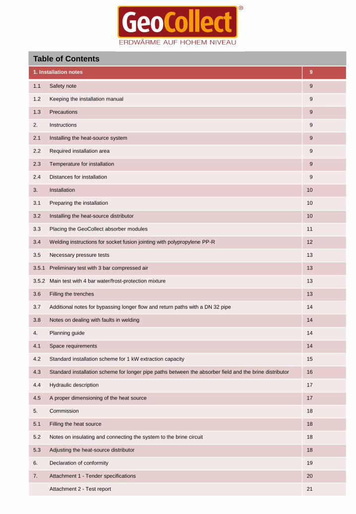
Table of Contents
1. Installation notes 9
1.1 Safety note 9
1.2 Keeping the installation manual 9
1.3 Precautions 9
2. Instructions 9
2.1 Installing the heat-source system 9
2.2 Required installation area 9
2.3 Temperature for installation 9
2.4 Distances for installation 9
3. Installation 10
3.1 Preparing the installation 10
3.2 Installing the heat-source distributor 10
3.3 Placing the GeoCollect absorber modules 11
3.4 Welding instructions for socket fusion jointing with polypropylene PP-R 12
3.5 Necessary pressure tests 13
3.5.1 Preliminary test with 3 bar compressed air 13
3.5.2 Main test with 4 bar water/frost-protection mixture 13
3.6 Filling the trenches 13
3.7 Additional notes for bypassing longer flow and return paths with a DN 32 pipe 14
3.8 Notes on dealing with faults in welding 14
4. Planning guide 14
4.1 Space requirements 14
4.2 Standard installation scheme for 1 kW extraction capacity 15
4.3 Standard installation scheme for longer pipe paths between the absorber field and the brine distributor 16
4.4 Hydraulic description 17
4.5 A proper dimensioning of the heat source 17
5. Commission 18
5.1 Filling the heat source 18
5.2 Notes on insulating and connecting the system to the brine circuit 18
5.3 Adjusting the heat-source distributor 18
6. Declaration of conformity 19
7. Attachment 1 - Tender specifications 20
Attachment 2 - Test report 21

9
1. Installation notes / 2. Instructions
1. Installation notes
1.1 Safety note
These installation instructions are mere tool for
the planning and installation of a heat-source
system.
It cannot be, and is not a replacement for
technical expertise and a professional planning.
1.2 Keeping the installation manual
The installation manual for the GeoCollect
Geothermal Energy Absorber System should be
kept with all other documents relevant to the
system.
1.3 Precautions
In order to ensure a flawless functionality of the
system as well as for warranty reasons it is
absolutely necessary to follow the steps in this
guide and to use the components specified by
GeoCollect GmbH.
2. 2. Instructions
2.1 Installing the heat-source system
The installation of the GeoCollect Geothermal
Absorber System must be carried out by
specialists. The proper commissioning of the
heat-source system for heating purposes is
warranted by the installer of the system.
The performance data (B0/W35) have been
determined for the climate area in Germany, at
440 meter above sea level, at a number of
2,000 hours per year in full operation (Heating
1,800 hours, Service water 200 hours), at 100 %
QN heating load for a standard building.
Important:
If the heat pump is laid out for less then
100% (<100%) of the required standard
heating load QN, the number of modules
must be recalculated due to their higher
operating hours.
2.2 Required installation area
The required installation area for GeoCollect
geothermal systems must be determined at the
planning stage by the installer of the system.
You will find a planning guide in section 4.
2.3 Temperature for installation
GeoCollect geothermal absorbers may only be
installed or mechanically loaded at both an
ambient temperature and a material temperature
of at least +5 °C. There is an increased risk of
breakage at temperatures below 5+ °C. The
ideal installation temperature is >+10 °C; the
handling of the absorbers requires a higher
carefulness at temperatures below +10 °C.
2.4 Distances for installation
I minimum distance of 0.30 m (upwards and side
wards) must be kept to supply lines of all kinds
when placing the GeoCollect geothermal
absorber modules in the ground. The modules
must not be covered with a pavement, sealed up
or overbuilt. Plantings are possible in principle,
however the roots must not grow deeper than 80
cm (please consult a gardening company if
necessary). The distance to the property line
should be at least 0.30 m, if possible 0.40 m -
local regulations may require a bigger distance.
UV light may have an adverse impact on the
material properties of GeoCollect geothermal
absorber modules, therefore they must be
protected from constant direct sunlight.
Important:
This product may not be used by children or
persons with reduced physical or mental
capabilities or insufficient experiences or
knowledge, unless they are under the
supervision or guidance of a person
responsible.
Subject to technical changes!

10
3. Installation
The installation must be performed in the
following order:
1. Determination of the required space
2. Excavation work
3. Placing of the modules and their connections
in rows of 5 modules; 2 rows must be
interconnected via DN 32 PP-pipe and fusion
sockets
4. Installation of the heat-source distributor
5. Welding the DN 20 flows and returns on the
module strings
6. Connecting the flows and returns to the
distributor
7. Pressure tests with protocol
8. Fixating and sluicing of the modules in the
trench with soil/sand
9. Backfill of the pit with stone-free excavated
material
3. Installation
Important:
The length of the DN 20 single connection tubes
from the distributor to the GeoCollect absorber rows
should not be exceed 10 m. Furthermore, DN 32
tubes must be used at lengths up to 150 m. The
pump performance must be adjusted accordingly
where necessary.
3.1 Preparing the installation
The GeoCollect absorber modules must be placed in
a depth of 1.50 m. The ground must be smooth and
free from sharp objects such as stones. The ground
must be covered before the modules can be placed.
Important:
The thermal transfer medium is a mixture of
ethylene and glycol with 29 % per volume and a
flocculation point of -15 °C. Components such as
the heat source distributor or flow and return
tubes must be installed in a way that they are
protected from frost, UV radiation and external
impacts (mechanical damage, animals, etc.).
Please observe your local weather conditions
(frost protection). It is not admissible to use any
other thermal transfer medium apart from the
medium recommended by the GeoCollect GmbH
(if necessary, please contact the GeoCollect
GmbH).
3.2 Installing the heat-source distributor
For hydraulic reasons, the heat-source distributor
cannot be placed farther away then 20 m from the
house and should be paced, for an easy venting,
at the highest point. If this distance cannot be met
due to practical reasons, the distributor must be
placed in close vicinity to the GeoCollect
geothermal absorbers, e.g. in an accessible well
casing. The connecting link from the heat pump to
the distributor must in this case be one size larger
than the connection with the appliance.
Illustration: Heat-source distributor in the pit, prior
to connection and insulating (first picture) and
after insulating on the wall (second picture)
If you wish to install the heat-source distributor at
the groundwork, a basement wall or inside of a
light shaft, you need to insulate it for example with
a rigid foam board placed between the wall and
the distributor toward the wall/groundwork.

11
3. Installation
3.3 Placing the GeoCollect absorber modules
Please make sure that there are always caps
attached to the open ends of the pipes when
placing them in the ground; this will prevent the
ingress of soil into the pipe system.
For the welding process, please observe the
attached "Welding instructions for socket fusion
jointing with polypropylene PP" (see section 3.4).
The pipes should be rolled out to the required
length and cut with cutting pliers (do not use a
saw); the cutting edges must be furnished with
sealing plugs immediately.
10 GeoCollect absorber modules make one string
each. In this process, 5 absorbers are being
welded together with the fusiotherm welding
process by use of the already affixed fusion
sockets on the absorber.
Both strings of 5 absorbers each will then be
interconnected at the socket less ends via 90°
fusion sockets and one 70 cm PP tube (DN 32).
DN 32 to DN 20 reduction sleeves must be
welded to the ends of each row of 5 absorbers
that facing the brine distributors, namely into the
sleeves/sockets attached to the absorber.
Subsequently, PP-tubes (DN 20) in a sufficient
length leading towards the brine distributor will be
welded to these reduction sleeves,
The flow and return pipes of the absorber rows
which lead to the brine distributors should be
placed on the ground with only a small distance in
between (do not bundle them!)
Welded connection of two absorbers
Illustration below: plug-connection as an installation aid
90° welded connection - the fusion sockets are at the socket-free
end of the absorber and are connected with a 70 cm DN 32 PP-
tube
Illustration on the left:
Welded connection from the absorber (on the socket
side) with DN 32 to DN 20 reduction sleeve and a
welded-on DN 20 tube (for connecting the bribe
distributor)
Important! It is absolutely necessary to install the expansion
vessel (diaphragm expansion tank, sole-proof)
provided by the customer!
Please observe the regulations according to DIN
4124 (10.02)!

12
3. Installation
3.4 Welding instructions for socket fusion
jointing with polypropylene PP
• Assemble the welding set and bring it up to
operating temperature (~ 240 °C). The welding
tools must be free of dirt and intact.
• It is recommended to use a pipe cutter to make
strait cut at the end of the pipe. The end must then
be cleaned from dust and dirt, and the depth of
insertion should be marked with a pen/marker
(see Table 3.4.1).
• Clean the fitting from dust and dirt.
• Push the fitting on the welding insert and warm it
up.
• Do not remove the fitting from the welding insert.
• Push the pipe on the welding insert until the
marked position is reached and warm it up. The
required warm-up time depends on the diameter
(see Table 3.4.1).
• Pull the fitting and the pipe simultaneously from
the welding inserts.
• Quickly, without twisting it, telescope the fitting
and the pipe, and hold it that way for several
seconds (see Table 3.4.1). Make sure not to push
the pipe too far into the socket (use markings with
a depth stopper).
• The necessary cooling-down time must be kept
(see Table 3.4.1).
Table 3.4.1
Reference values for heating-element socket welding of PP-pipes at an outdoor temperature of 20 °C and
moderate air movement.
Important!
The welded connection do not reach strength before circa 30 minutes!
The welding insert must, upon placing the reduction sleeves, be changed from DN 32 to DN20 after the
module rows have been welded.
Caution! Risk of burns! Disconnect the welding set from the mains and let it cool down first!
Diameter
outer pipe Welding
penetration
depth
Fitting
warm-up
time
Pipe warm-
up time
Max. Processing
time
Holding
time
Cooling
down
time
20 mm 10 mm 4-5 s 3-5 s 3-5 s 10 s 4 min.
32 mm 10 mm 8-10 s 8-9 s 3-5 s 10 s 4 min.

13
3. Installation
3.5 Necessary pressure tests
3.5.1 Preliminary test with 3 bar compressed
air
A preliminary test of the entire installation with a
pressure of 3 bar must be performed prior to the
filling of the trenches.
The installation must be checked for leakages. It
is necessary to create a properly filled in protocol
on the successfully performed preliminary
compressed air test (see attachment 1).
3.5.2 Main test with 4 bar water-glycol
mixture (safe at temperatures up to -15 °C)
Upon a successfully performed preliminary test
the system must be filled with a water-glycol
mixture and put under a test pressure of 4 bar.
This test state must be maintained during a
course of at least 12 hours and needs to be
logged in detail (see attachment 3).
After the test has been successfully finished,
other trades and maintenance groups may start
their own work. The heat-source system,
however, must be
kept under the above mentioned test pressure,
so that any leakage caused by other trades can
be discovered and repaired immediately.
In the event that other trades or maintenance
groups will not start their work immediately
following the pressure test, the installation must
be discharged for the time being, that is the
pressure within the system must be reduced to
the intended operating pressure. As soon as the
follow-on works about to be started, increase the
pressure to 4 bar again.
All test protocols must be sent duly completed to
the GeoCollect GmbH.
Important:
Sending the test protocols within a
reasonable period of time (2 weeks) after the
pressure test, and the application of the
system components recommended by the
GeoCollect GmbH is a requirement for the
extended 10-year warranty (excluding the
absorber modules) of the product liability
insurance.
Important:
Do not use the GeoCollect geothermal
absorber system as a dry heater for screed
or the building, especially not if the heating
period is about to begin soon: the
recuperation time of the system accounts for
a whole summer. Dry heating must be done
with a different heater (e.g. heating
cartridges). If you wish to use the brine/water
heat pump for the heating of pools too, you
must expect an increased number of annual
hours of full use, and need to extend the heat
source.
3.6 Filling the trenches
The modules must be fixated with a thin layer of
soil (or sand, according to DIN 4022 rough sand
or sand with grains of 0.63-2.00 mm in diameter)
sluiced before the complete filling of the pit.
Construction equipment (such as excavators)
must not drive over the installation area before
the trenches have been completely filled and
well compressed (proctor density of more than
90 %), this may lead to a damaging of the
modules.
14
3. Installation
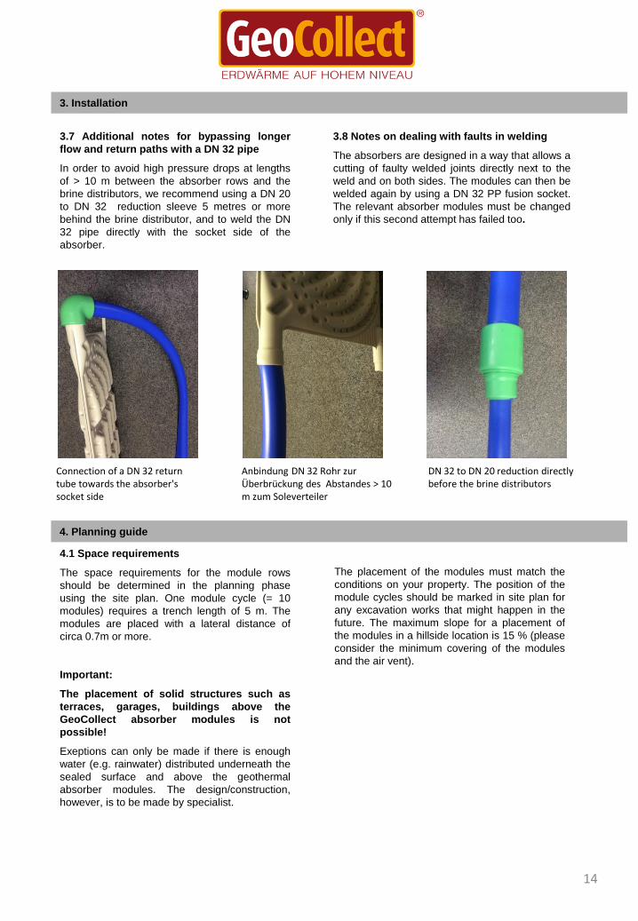
4.1 Space requirements
The space requirements for the module rows
should be determined in the planning phase
using the site plan. One module cycle (= 10
modules) requires a trench length of 5 m. The
modules are placed with a lateral distance of
circa 0.7m or more.
Important:
The placement of solid structures such as
terraces, garages, buildings above the
GeoCollect absorber modules is not
possible!
Exeptions can only be made if there is enough
water (e.g. rainwater) distributed underneath the
sealed surface and above the geothermal
absorber modules. The design/construction,
however, is to be made by specialist.
The placement of the modules must match the
conditions on your property. The position of the
module cycles should be marked in site plan for
any excavation works that might happen in the
future. The maximum slope for a placement of
the modules in a hillside location is 15 % (please
consider the minimum covering of the modules
and the air vent).
4. Planning guide
3.7 Additional notes for bypassing longer
flow and return paths with a DN 32 pipe
In order to avoid high pressure drops at lengths
of > 10 m between the absorber rows and the
brine distributors, we recommend using a DN 20
to DN 32 reduction sleeve 5 metres or more
behind the brine distributor, and to weld the DN
32 pipe directly with the socket side of the
absorber.
3.8 Notes on dealing with faults in welding
The absorbers are designed in a way that allows a
cutting of faulty welded joints directly next to the
weld and on both sides. The modules can then be
welded again by using a DN 32 PP fusion socket.
The relevant absorber modules must be changed
only if this second attempt has failed too.
Connection of a DN 32 return tube towards the absorber's socket side
Anbindung DN 32 Rohr zur Überbrückung des Abstandes > 10 m zum Soleverteiler
DN 32 to DN 20 reduction directly before the brine distributors

15
4. Planning guide
4.2. Standard installation scheme for 1 kW extraction capacity
Flo
w f
rom
hea
t p
um
p t
o t
he
abso
rber
s
Ret
urn
to
hea
t p
um
p
Rows with 5 absorbers each
Welded connections between t he absorbers
Interconnection between the rows of modules with a DN 32 PP pipe
90° DN 32 fusion sockets
Reduction sleeves 32 to 20 mm
20 mm PP tube connecting the brine distributor
Brine distributor with flow limiter
Brine distributor with ball valves
Return to heatpump
Flow from heatpump

16
4. Planning guide
4.3. Installation scheme for strings with bigger distances to the brine distributor
Vo
rlau
f vo
n d
er W
ärm
ep
um
pe
in d
ie A
bso
rber
Rü
ckla
uf
zur
Wär
me
pu
mp
e
Rows of 10 absorbers each
Welded connection between the absorbers
90° fusion sockets for DN 32
32 mm to 20 mm reduction sleeves
32 mm PP pipe for bypassing longer distances (up to 150 m)
20 mm PP pipe connecting the brine distributor
DN 32 fusion sockets
17
4. 4. Planning guide
4.2 Hydraulic description
The connection of the heat pump to the flow and
return distributor for brine/water heat pump
systems with a ventilation module and absorber
modules, heat-source distributor, charging and
discharging armature and diaphragm pressure
expansion vessel must be made as follows:
The outlet side of the appliance must be
connected with the flow distributor.
The inlet side must be connected to the return
distributor (distributor with flow limiters). The
individual flows of the modules must be aligned;
the highest possible flow should be achieved
(see Setting Table 5.3.1)
The distances of 0.35 or 0.70 respectively
should always be considered in the planning
stage
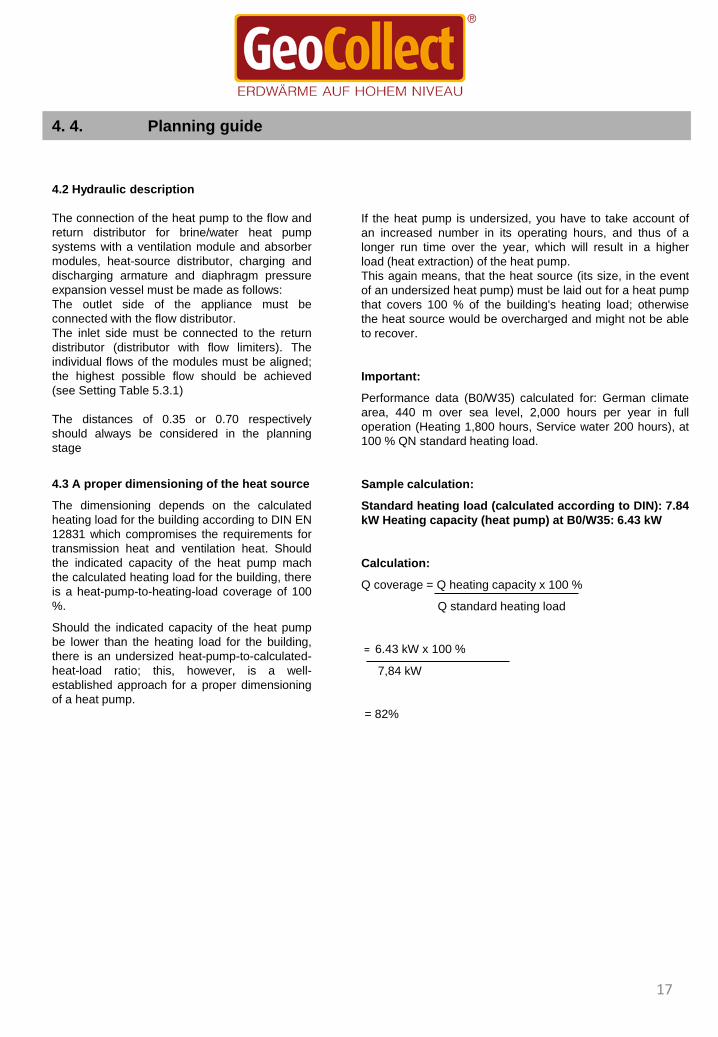
4.3 A proper dimensioning of the heat source
The dimensioning depends on the calculated
heating load for the building according to DIN EN
12831 which compromises the requirements for
transmission heat and ventilation heat. Should
the indicated capacity of the heat pump mach
the calculated heating load for the building, there
is a heat-pump-to-heating-load coverage of 100
%.
Should the indicated capacity of the heat pump
be lower than the heating load for the building,
there is an undersized heat-pump-to-calculated-
heat-load ratio; this, however, is a well-
established approach for a proper dimensioning
of a heat pump.
If the heat pump is undersized, you have to take account of
an increased number in its operating hours, and thus of a
longer run time over the year, which will result in a higher
load (heat extraction) of the heat pump.
This again means, that the heat source (its size, in the event
of an undersized heat pump) must be laid out for a heat pump
that covers 100 % of the building's heating load; otherwise
the heat source would be overcharged and might not be able
to recover.
Important:
Performance data (B0/W35) calculated for: German climate
area, 440 m over sea level, 2,000 hours per year in full
operation (Heating 1,800 hours, Service water 200 hours), at
100 % QN standard heating load.
Sample calculation:
Standard heating load (calculated according to DIN): 7.84
kW Heating capacity (heat pump) at B0/W35: 6.43 kW
Calculation:
Q coverage = Q heating capacity x 100 %
Q standard heating load
= 6.43 kW x 100 %
7,84 kW
= 82%

18
5. Commission
5. Commission
5.1 Filling the heat source
The GeoCollect absorber installation must be
rinsed and air vented right after its pressure test
(see 3.5). Prior to this, the pressure in the
expansion vessel on the side of the brine must
be checked and adjusted to 0.5 to 0.7 bar. The
operating pressure should be 1.0 to 1.2 bar.
For flushing you should by all means use a
flushing/rinsing system, which can be connected
to the charging and discharging armature
installed on the heat-source inlet side. Close the
suthoff valve on this armature prior to the
flushing, so that no brine flow can occur. Then
open the shutoff valves at the rinsing system and
activate its circulation pump, which will then
circulate the brine fluid from its own vessel
through the heat pump and the absorber
modules.
The brine cycle is full as soon as brine liquid
begins to flow back into the vessel coming from
the upper inlet connection. Now the brine pump
in the heat pump can be activated. Close all but
one connections at the brine distribution
manifold in order to rinse all module cycles dirt-
and bubble-free. This way it will be ensured that
also this string is rinsed thoroughly and all
possible bubbles or particles are sluiced out. The
rinsing for each string is sufficient when there
are no bubbles or no formations of foam visible
at the returning brine.
Now open the next string, and close the one that
was previously rinsed. Continue in this order until
all strings have been rinsed in turn.
5.2 Notes on insulating and connecting the
system to the brine circuit
The connecting curves in the heat pump must be
checked for proper insulation; non-insulated parts
must be insulated. Choosing the right insulating
material and a proper workmanship is very
important. A thickness of the chosen insulating
material,
which must be diffusion-proof, of at least 19 mm is
compulsory (plus UV-resistance at outdoor
installations).
5.3 Adjusting the heat-source distributor
A proper functionality of the heat-source system
requires a hydraulic compensation at the heat-
source distributor - this will hydraulically align all
modules.
All regulating valves at the distributor manifold must
be fully open. All flow limiters at the distributor
manifold must be set to the highest possible flow
rate by using the regulating valve, and must be
hydraulically aligned. This will ensure an even and
ideal mass flow per module cycle, and the brine
flow will be achieved at the lowest possible
pressure loss.
Table GeoCollect 5.3.1 (see also 4.2)

6. Declaration of conformity
GeoCollect GmbH - Geothermal Engergy Absorber System
Declaration of Conformity
We hereby declare the safeness of our products, which correspond to the state-of-the-art and comply with common
regulations. Their operation in accordance with the intended use does not pose a risk to the user.
Certificate of Compliance
GeoCollect Geothermal Absorber System
We hereby certify, that the used polypropylene (PP) is physiologically and toxicologically safe. The German Federal
Board of Health (Bundesgesundheitsamt, BGA) regulates in its Recommendation No. 7 "Polypropylene" its use in the
manufacture of commodities as referred to in Paragraph 5.1 No. 1 of the German Foodstuffs and Commodities Act
(Lebensmittel- und Bedarfsständegesetz, LMBG). Accordingly, polypropylene complies with the regulation of the
German BGA, memorandum 152, page 25 of 1 April 1982 as well as with the valid KTW guidelines (KTW Guideline =
Guideline for the Hygienic Assessment of Organic Materials in Contact with Drinking water); plastics, containers and
fasteners may without any concern be made from polypropylene. Furthermore, polypropylene may be used for the
manufacture of pharmaceutical containers.
The KTW-Recommendations for health assessment of plastics and other non-metallic materials apply to drinking water
supply systems. Polypropylene complies with these regulations. Polypropylene is neutral to ground water and is not
broken down by microorganisms.
The chemical composition of the polypropylene in use complies with national and international regulations for the use
of materials that come into contact with potable water.
The polypropylene used by GeoCollect GmbH has been tested by the German Versuchsanstalt für Kunststofftechnik
und Großchemie (Reseach Institute for Plastics Technology and the Chemical Industry).
During this examination it was found that there is a compliance with the following guidelines:
• the List of monomeres No. 260/92 of the German Department of Trade and Industry
• the List of monomeres of the European Union, directive No. 90/128/EEC and 92/93 EEC and 93/9 EEC
• the BGA whitelist (of the German Federal Board of Health) for polypropylene
• the KTW-whitelist (Germany) for polypropylene that is in contact with water
The polypropylene used by us meets the requirements for products that are in contact with foodstuffs in the following
countries:
Belgium, Germany, Great Britain, Italy, The Netherlands, Spain and the European Community.
Marienberg, March 2014
18
GeoCollect® GmbH • Max-Brauer-Allee 218 • 22769 Hamburg • • Tel +49 (0)40/2263306 13 • Fax +49 (0)40 / 2 263606 66 •
• Mail: [email protected]• www.geocollect.de • • Geschäftsführer: Wolfgang Seifert • Handelsregister: Amtsgericht Hamburg • HRB 132417
Bank: DKB IBAN: DE93 1203 0000 1020 1091 44 BIC: BYLADEM1001• USt.-ID: DE 815 332 719

Attachment 1: Tender specifications for a GeoCollect Geothermal Absorber
System
Tender specification: Geothermal Absorber System BOQ: Sanitation and heating technology Trade: Heat supply engineering Titel: Ground collector Type: GeoCollect-Geothermal Absorber Modules Item No.: EWAM02PP32 Description of the appliance: Rows of modules of ground collectors for the exploitation of near-surface geothermal energy by means of an absorber system. The modules are made from soil-resistant plastics (polypropylene). Vertically standing modules are installed, each with a maximum number of 10 modules per cycle, including shaped pieces and a DN 32 pipe. The modules will be interconnected with a polyfusion welding. The modules will be installed in trenches with a width of about 70 cm and a depth of about 1.50 m. The distance between the brine distributor and the absorber field must not exceed 20 m. The WätaS Wärmepumpen Sachsen GmbH Planning and Installation Manual must be observed. Technical Specifications: Dimensions (LxWxH): 990 x 350 x 40 mm Material: Polypropylene (PP) Wight: 1.700 g Surface extraction capacity: 142,61 W/m² Cooling capacity: 99,83 Watt/module Pressure drop per module: 96 Pa Pressure drop per string: circa 2 kPa (mit 2 x5 m DN 20 Anschlussrohr PP) pipe Operating pressure of the modules: 0,8 to max. 1,2 bar Flow rate per string: 5 l/min Filling capacity: 2 l Maximum string: 10 modules Installation: standing Essential accessories: 50 m DN 32 pipes (approx. 25 m per String), 50 m DN 20 pipes (approx. 6 m per string), DN 32 thermo fusion sockets, DN 32 90° elbow joints (2 pcs. per string), 32x20 reduction sleeves (2 pcs. per string), brine distributor return with flow limiters, brine distributor flow with ball valves, brine filling station, brine (29% ehtylenglycol) circa 50 l per row of modules. The pit for the brine distributor, ground works and installation are provided by the customer.

Attachment 2: Pressure-test protocoll
GeoCollect geothermal absorber system – Pressure test
Project: Ausführende Firma:
Project manager: Protocol No.:
Pressure test with air Pressure test with brine
Nro.: Section Pressure Time Date Signature Notes
1 Start
End
2 Start
End
3 Start
End
4 Start
End
5 Start
End
6 Start
End
7 Start
End
8 Start
End
9 Start
End
10 Start
End
11 Start
End
12 Start
End
13 Start
End
14 Start
End
15 Start
End
Important: The generation of properly issued protocols on all performed pressure tests is a necessary requirement for the extended 10-year warranty provided by GeoCollect GmbH on the supplied geothermal absorber modules.
I hereby confirm, that I have successfully performed a pressure test for the above sections in accordance with the GeoCollect installation manual.
Person performing the test Date / Signature