application reference number: wwo10001 … and bridge assessments central zone cso works: interface...
TRANSCRIPT

Tunnel and Bridge AssessmentsCentral ZoneCSO Works: Interface Assessment – Vauxhall BridgeDoc Ref: 9.15.58
Folder 101 September 2013DCO-DT-000-ZZZZZ-091500 CS
O W
orks
: Int
erfa
ce A
sses
smen
t –
Vaux
hall
Brid
ge
Thames Tideway Tunnel Thames Water Utilities Limited
Application for Development ConsentApplication Reference Number: WWO10001

DRAFT AND CONFIDENTIAL
Vauxhall Bridge - CSO Interface Assessment 315-RG-TPI-BR010-000010 Revision - AB Date approved -
i Uncontrolled when printed Printed 12/09/2012
DRAFT AND CONFIDENTIAL
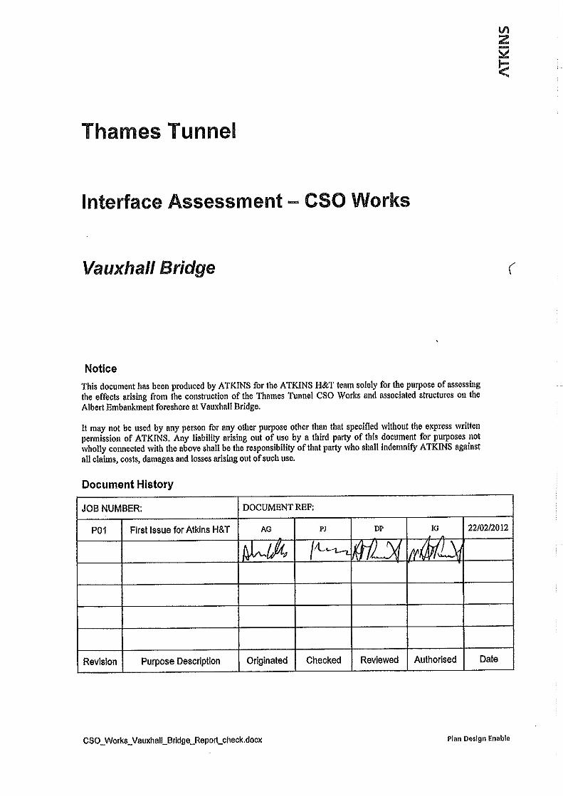
Thames Tunnel
CSO works: Interface Assessment – Vauxhall Bridge
List of contents
Page number
1. Executive Summary ......................................................................................... 1
2 Structural Description ..................................................................................... 2
2.1 Structural Outline ..................................................................................... 2
2.2 Structural Type ........................................................................................ 3
2.3 Foundation Type ...................................................................................... 3
2.4 Span Arrangements ................................................................................. 3
2.5 Articulation Arrangements ....................................................................... 3
2.6 Road Restraint System Type ................................................................... 3
3 Description of CSO Works .............................................................................. 4
3.1 Existing CSO Interface ............................................................................ 4
3.2 Proposed CSO Works ............................................................................. 4
3.3 Permanent works ..................................................................................... 4
3.4 Temporary Works .................................................................................... 5
4 Detailed Description of Thames Tunnel CSO Works .................................... 7
4.1 Site Establishment ................................................................................... 7
4.2 Construction ............................................................................................ 8
4.3 Permanent Phase .................................................................................. 13
5 Impacts of the CSO Works on the Structure ................................................ 14
5.1 Impact due to Demolition ....................................................................... 14
5.2 Impact due to construction..................................................................... 14
5.3 Impact Due to Permanent Phase ........................................................... 16
6 Conclusions and Recommendations ........................................................... 17
Appendices ............................................................................................................. 20
Appendix A – TT CSO Drawings ........................................................................... 21
Appendix B – Geotechnical Assessment Report ................................................. 30
Appendix C – CSO Assessment Methodology ..................................................... 31
Appendix D – CSO Fluvial Flow and Scour Review ............................................. 38

DRAFT AND CONFIDENTIAL
Vauxhall Bridge - CSO Interface Assessment 315-RG-TPI-BR010-000010 Revision - AB Date approved -
ii Uncontrolled when printed Printed 12/09/2012
DRAFT AND CONFIDENTIAL
List of figures
Page number
Figure 3.1 Clapham CSO .......................................................................................... 5
Figure 3.3 Vauxhall Bridge Abutment and River wall ................................................. 6
Figure 3.4 Foreshore Area ......................................................................................... 6
List of tables
Page number
None
List of Abbreviations
CSO Combined Sewer Overflow
TA Technical Approval
RFI Request for Information
EPP Preliminary Emergency Preparedness Plan

1 Executive Summary
Vauxhall Bridge - CSO Interface Assessment 315-RG-TPI-BR010-000010 Revision - AB Date approved -
Page 1 Uncontrolled when printed Printed 12/09/2012
DRAFT AND CONFIDENTIAL
1. Executive Summary
1.1.1 The location of Vauxhall Bridge means that there are existing Combined Sewer Overflow (CSO’s) in the river wall either side of the south abutment. These CSO’s currently discharge directly into the River Thames.
1.1.2 As part of the Thames Tunnel scheme it is proposed to redirect the existing CSO’s into an enclosed system which will ultimately discharge into the Thames Tideway Tunnel.
1.1.3 Significant construction works are required to achieve the redirection of the existing CSO’s, including works adjacent to the bridge structure.
1.1.4 This report discusses the interface issues to be considered in the development of the CSO design and the assessment of Vauxhall Bridge for the effects of the proposed works.
1.1.5 The “Combined Sewer Overflow” works and associated structures on the Albert Embankment foreshore at Vauxhall Bridge include the installation and removal of temporary sheet piling below, upstream and downstream of the first span of the bridge, the construction of a combined interception and valve chamber structure serving both the existing Clapham and Brixton CSO’s, Connection Culvert and Culvert Reception Shaft with storm overflow, and embankment reconstruction with terracing.
1.1.6 A meeting was held with the CSO design team on 20th January to discuss the identified interface issues. The outcome of this meeting is discussed within this report.

2 Structural Description
Vauxhall Bridge - CSO Interface Assessment 315-RG-TPI-BR010-000010 Revision - AB Date approved -
Page 2 Uncontrolled when printed Printed 12/09/2012
DRAFT AND CONFIDENTIAL
2 Structural Description
2.1 Structural Outline
2.1.1 The current Vauxhall Bridge was designed by Sir Alexander Binnie. It was constructed between 1898 and 1906 and is located between Lambeth Bridge and Grosvenor Bridge.
2.1.2 Vauxhall Bridge is a five span steel arch bridge carrying the A202 Vauxhall Bridge Road over the River Thames in Central London and links Vauxhall Cross with Pimlico. The bridge view is shown in figure 2.1.
2.1.3 The width of the structure between parapets is 24.4m with footways of approx 2.65m wide. The structure has 4 lanes of traffic, 2 in each direction, plus 2 bus lanes, again 1 in each direction, and one cycle lane.
2.1.4 The deck is formed from flat steel plates overlaid by a mass concrete slab and protected with bituminous waterproofing below the asphalt carriageway surface. Concrete paving slabs cover the footways. The carriageway has a transverse crossfall to facilitate drainage and gullies are positioned along the entire length of the structure to collect and drain the carriageway.
2.1.5 The main deck is supported on cross beams which are themselves supported on the main longitudinal members. The longitudinal members are supported on spandrel columns which stem from the arch ribs.
2.1.6 The ribs forming the arch span are spaced at 1.97m centres which support the spandrel column locations, which are at 3.15m centres. The outer ribs support the footway and 11No inner ribs support the carriageway (there are a total number of 13 arch ribs per span). The outer ribs are shallower in depth than the inner ribs supporting the roadway. The inner ribs also vary in cross section along their span. All the ribs and spandrel columns are cross braced vertically. There are several other cross members used in the structure including deck cross beams, spandrel vertical cross bracing, diagonal wind bracing and rib vertical cross bracing which make up the structure.
2.1.7 The structure is supported by four piers and two abutments which comprise granite face concrete chambers founded on steel caissons filled with concrete. The Westminster abutment is also supported by a series of piles.
2.1.8 Knuckle pin bearings are located at the ends of the arch ribs. The longitudinal beams are supported on rubber pad bearings at the abutment location. Sliding plates are used within the deck expansion joints.
2.1.9 There are 10 expansion joints, 2 are located at each of the piers and 1 at each abutment. This structure has a history of problems with the expansion joints and refurbishment work was carried out on the joints in 2002. New joints were installed between 1987 and 1994, the deck modifications around the joints are unknown.
2 Structural Description
Vauxhall Bridge - CSO Interface Assessment 315-RG-TPI-BR010-000010 Revision - AB Date approved -
Page 3 Uncontrolled when printed Printed 12/09/2012
DRAFT AND CONFIDENTIAL
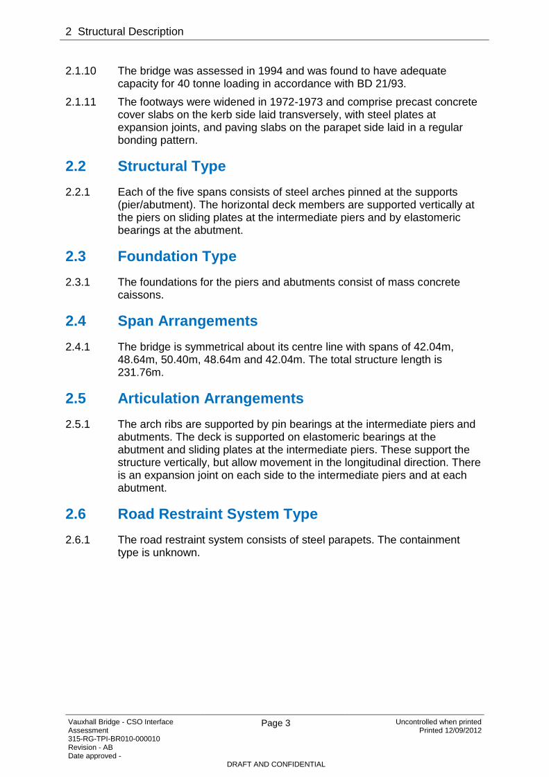
2.1.10 The bridge was assessed in 1994 and was found to have adequate capacity for 40 tonne loading in accordance with BD 21/93.
2.1.11 The footways were widened in 1972-1973 and comprise precast concrete cover slabs on the kerb side laid transversely, with steel plates at expansion joints, and paving slabs on the parapet side laid in a regular bonding pattern.
2.2 Structural Type
2.2.1 Each of the five spans consists of steel arches pinned at the supports (pier/abutment). The horizontal deck members are supported vertically at the piers on sliding plates at the intermediate piers and by elastomeric bearings at the abutment.
2.3 Foundation Type
2.3.1 The foundations for the piers and abutments consist of mass concrete caissons.
2.4 Span Arrangements
2.4.1 The bridge is symmetrical about its centre line with spans of 42.04m, 48.64m, 50.40m, 48.64m and 42.04m. The total structure length is 231.76m.
2.5 Articulation Arrangements
2.5.1 The arch ribs are supported by pin bearings at the intermediate piers and abutments. The deck is supported on elastomeric bearings at the abutment and sliding plates at the intermediate piers. These support the structure vertically, but allow movement in the longitudinal direction. There is an expansion joint on each side to the intermediate piers and at each abutment.
2.6 Road Restraint System Type
2.6.1 The road restraint system consists of steel parapets. The containment type is unknown.

3 Description of CSO Works
Vauxhall Bridge - CSO Interface Assessment 315-RG-TPI-BR010-000010 Revision - AB Date approved -
Page 4 Uncontrolled when printed Printed 12/09/2012
DRAFT AND CONFIDENTIAL
3 Description of CSO Works
3.1 Existing CSO Interface
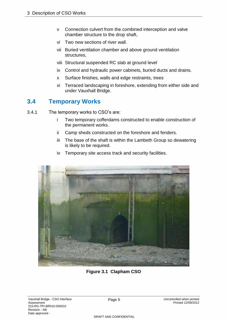
3.1.1 The existing CSO’s discharge either side of the south abutment, with the Clapham CSO to the West and Brixton CSO to the East. Wooden fenders are present where the outflow channel extends into the river bed. River bed materials in the vicinity of the CSO, beyond the outfall, predominantly comprise small stone, gravel, sand and mud.
3.1.2 The existing CSO’s are shown in Figure 3.1 and Figure 3.2.
3.2 Proposed CSO Works
3.2.1 Proposed CSO works at this location include construction of a combined interception and valve chamber structure serving both the existing Clapham and Brixton CSO’s at the current outlet locations. See Figure A.1 for plan of existing site features and Figure A.6 for planned Interception Chamber. This chamber will redirect outflow in to a culvert to be constructed below existing ground level. This culvert will carry outflow perpendicular to the bridge structure, parallel with the river wall.
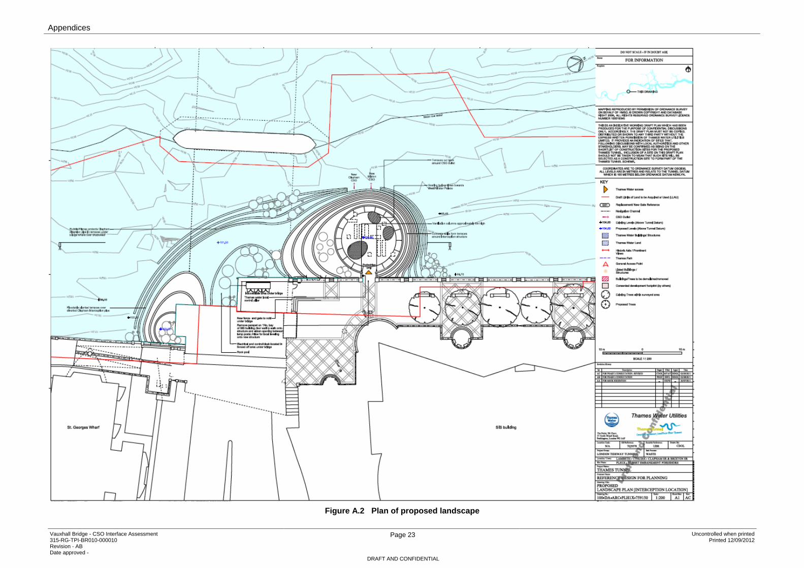
3.2.2 An area of foreshore, located to the East of Vauxhall Bridge, will be developed to accommodate an interception chamber and drop shaft, together with accompanying apparatus. This will form a permanent amendment to the river wall. See Figure A.2 for plan of the proposed landscape.
3.2.3 The redirected CSO’s will extend in to the connection culvert and drop shaft within the foreshore extension. See Figure A.7 and A.8 for shaft and connecting culvert. From there the outflow will discharge in to the Thames Tunnel via a sprayed concrete lined connection tunnel.
3.2.4 The proposed CSO works, including foreshore extension are located within the London Borough of Lambeth
3.2.5 All plans of the proposed CSO works are included within Appendix A.
3.2.6 The existing foreshore at the Vauxhall Bridge is shown in Figure 3.4.
3.3 Permanent works
3.3.1 The CSO permanent works includes:
i An Offline CSO drop shaft,
ii A combined interception and valve chamber structure serving both the existing Clapham and Brixton CSO’s Interception chamber,
iii A connection tunnel from the drop shaft to the main tunnel,
iv Connection culverts from each of the two existing CSO outlets to the respective interception chambers,
3 Description of CSO Works
Vauxhall Bridge - CSO Interface Assessment 315-RG-TPI-BR010-000010 Revision - AB Date approved -
Page 5 Uncontrolled when printed Printed 12/09/2012
DRAFT AND CONFIDENTIAL
v Connection culvert from the combined interception and valve chamber structure to the drop shaft,
vi Two new sections of river wall.
vii Buried ventilation chamber and above ground ventilation structures,
viii Structural suspended RC slab at ground level
ix Control and hydraulic power cabinets, buried ducts and drains.
x Surface finishes, walls and edge restraints, trees
xi Terraced landscaping in foreshore, extending from either side and under Vauxhall Bridge.
3.4 Temporary Works
3.4.1 The temporary works to CSO’s are:
i Two temporary cofferdams constructed to enable construction of the permanent works.
ii Camp sheds constructed on the foreshore and fenders.
iii The base of the shaft is within the Lambeth Group so dewatering is likely to be required.
iv Temporary site access track and security facilities.
Figure 3.1 Clapham CSO

3 Description of CSO Works
Vauxhall Bridge - CSO Interface Assessment 315-RG-TPI-BR010-000010 Revision - AB Date approved -
Page 6 Uncontrolled when printed Printed 12/09/2012
DRAFT AND CONFIDENTIAL
Figure 3.2 Brixton CSO
Figure 3.3 Vauxhall Bridge Abutment and River wall
Figure 3.4 Foreshore Area

4 Detailed Description
Vauxhall Bridge - CSO Interface Assessment 315-RG-TPI-BR010-000010 Revision - AB Date approved -
Page 7 Uncontrolled when printed Printed 12/09/2012
DRAFT AND CONFIDENTIAL
4 Detailed Description of Thames Tunnel CSO Works
A review of demolition, construction and permanent phases of the CSO works has been undertaken. The following works have been identified within these phases.
4.1 Site Establishment
4.1.1 The access to the main Eastern part of the site will be from Albert Embankment down a single lane width access track to be built alongside the existing access track to lack’s Dock.
4.1.2 The Western part of the site (Vauxhall Bridge) will be accessed by personnel by foot along the foot path in front of the SIS building and by low ground bearing machines along the foreshore during low tide. A new ramp will be constructed with granular fill material for plant and materials deliveries accessing the top of the cofferdam
4.1.3 Prior to any works commencing the site boundary will be established and secured. The boundary will consist of 2.4m high close boarded hoarding panels, attached to timber posts concreted in the ground unless there are any site specific security requirements.
4.1.4 Access gates will provide access/egress off of the eastbound Albert Embankment carriageway. The gates will be manned by a security contractor. Additional security measures will be required due to close proximity of the SIS building.
4.1.5 On completion of the river works, as detailed in Section 4.2, the cofferdam will be backfilled with granular material loaded from a barge. The opportunity to use excavated material from another site will be investigated. A tracked excavator and twin drum vibratory roller will be used to spread and compact the fill material.
4.1.6 The site will be set up to provide office and welfare facilities. Typically these consist of units delivered to site on a flatbed lorry. Simple concrete foundation pads will be cast to provide a stable base. The units will be off loaded and positioned either using a HIAB mounted on the lorry or a small mobile crane (25 to 50 tonnes depending on required radius).
4.1.7 Water (100mm) and power (1.1MVA) will be mains connected if available. If not available power will be supplied by a generator. Water will be stored in a tank and pumped on demand and re-supplied as required.
4.1.8 Plant and material storage areas for shaft and tunnel connection works, waste skips, muck bin and delivery vehicle turning area will be set up on site. Major plant required for the diaphragm wall works include cranes, clamshell grab, Hydromill/Hydrofraise diaphragm wall rig, 40t bentonite silo’s, water tanks, 20m³ mixing pan, 150cfm compressor, air receiver, excavator and dumper for excavated material movement.

4 Detailed Description
Vauxhall Bridge - CSO Interface Assessment 315-RG-TPI-BR010-000010 Revision - AB Date approved -
Page 8 Uncontrolled when printed Printed 12/09/2012
DRAFT AND CONFIDENTIAL
4.1.9 The connection tunnel will be constructed using SCL techniques. A telehandler or small crane will be in constant use on site to manage materials and deliveries.
4.2 Construction
River Works
4.2.1 Prior to commencement of river works, a Navigational Risk Assessment should be agreed with the Port of London Authority (PLA) and a notice to mariners posted. All relevant licenses for the occupation of the requisite site area within the river and the associated River Works License will need to be in place.
4.2.2 River navigational supports such as lights, signage, dolphins and buoys will be installed to exclude any river traffic (other than required for construction). The authorised channel will not be impinged or used for access to and from the site.
4.2.3 Temporary sheet piled walls are to be installed to form a watertight cofferdam. The piling required for the permanent realigned river wall and slipway will be installed concurrently with the temporary cofferdam piling.
4.2.4 A jack up barge (Hydraulically operated self elevating platform) will be mobilised to access and service the site.
4.2.5 A campshed is intended to be constructed on the foreshore adjacent to the temporary piled wall to facilitate barge deliveries to site.
4.2.6 Once the cofferdam walls have been completed, additional investigations will be undertaken at the location of the interception chamber and shaft to ensure all obstructions are removed prior to filling the cofferdam.
Interception and CSO Works
4.2.7 The Flow from the two existing outfalls (Clapham CSO and Brixton CSO) will be channeled to the interception chamber constructed in front of SIS building. The new outfall structures and culvert connections will be constructed of cast in-situ reinforced concrete.
4.2.8 The interception chamber will be constructed within the cofferdam in front of the SIS building by installing a secant or secant piled box with internal structures formed with in-situ concrete.
4.2.9 The connection from the existing outfalls to this chamber will be formed by precast pipes installed using trenching techniques within the cofferdam. In-situ concrete end connections will be required.
4.2.10 The interception chamber will be internally sub-divided to separately deal with the respective flows from each of the two existing CSO outlets. Each flow stream will drop below riverbed level and pass through a set of valves before dropping again to the deeper level of the connection culvert. At the deeper level both flow streams combine and pass along the connection culvert to the drop shaft. Each flow stream will have a separate high level overflow with tidal flap valves that discharge to a new CSO outlet to the river

4 Detailed Description
Vauxhall Bridge - CSO Interface Assessment 315-RG-TPI-BR010-000010 Revision - AB Date approved -
Page 9 Uncontrolled when printed Printed 12/09/2012
DRAFT AND CONFIDENTIAL
4.2.11 The interception chamber will be connected to the main shaft by a connection culvert constructed by SCL techniques.
4.2.12 The interception chamber will be constructed inside an excavation within the cofferdam. Submersible pumps will discharge to the river after being treated through a “Siltbuster’ type settlement system.
4.2.13 Steel bar reinforcement will be built for the base of the interception chamber. The base sides and wall kicker shutters will be installed and the base concreted.
4.2.14 After striking the base shuttering, internal wall formwork will be assembled on the base and lifted by telehandler, located on the surface, into position at the wall kicker and secured with push pull props. When the internal panels are complete and fully braced the external wall panels will be positioned and secured to the internal panels with through ties. A portal will be incorporated within the wall pour to receive the connection tunnel.
4.2.15 The process will be repeated for the second and third lifts. Scaffold staging will be assembled for access to install reinforcement, formwork, place and compact concrete.
4.2.16 A falsework support system will be assembled within the chamber and a formwork deck installed. Soffit steel bar reinforcement will be built and side panel formwork installed. The soffit concrete will be pump placed.
4.2.17 All sheet piling installed for the Clapham and Brixton outfall connections will be extracted by piling rig with any remaining fill removed by barge.
CSO Drop Shaft Execution
4.2.18 The CSO drop shaft will be constructed within the area of foreshore extension located to the east of the bridge structure. Consequently the CSO drop shaft construction is anticipated to have a negligible effect of bridge settlements.
4.2.19 The shaft will be constructed by diaphragm wall construction techniques and have a cast in-situ secondary lining.
4.2.20 To facilitate the diaphragm wall construction, inner and outer guide walls are constructed using traditional shuttering techniques. Fill material will be excavated for the extent of the guide walls. The sides of the excavation will be battered to maintain ground stability. Concrete blinding will be placed at formation level directly from the concrete mixer truck.
4.2.21 Steel bar reinforcement cage will be built on the blinding.
4.2.22 Panel formwork will be assembled and positioned on the blinding. The formwork will be secured and the guide walls concreted. Concrete will be delivered to site in ready mix concrete mixer trucks and discharged into a truck mounted boom pump, and pumped into the formwork. The formwork will be struck when the guide walls have cured.
4.2.23 A working platform for the crane will be concreted within the inner guide walls, poured via a truck mounted boom pump.
4.2.24 Diaphragm wall construction plant will be set up on site. This is primarily 40t bentonite silos, water tanks, bentonite mixing pan, bentonite storage

4 Detailed Description
Vauxhall Bridge - CSO Interface Assessment 315-RG-TPI-BR010-000010 Revision - AB Date approved -
Page 10 Uncontrolled when printed Printed 12/09/2012
DRAFT AND CONFIDENTIAL
tanks, crawler cranes, a hydro mill / hydro fraise diaphragm walling rig and slurry separation plant. At this stage for the diaphragm wall construction a hydro mill method is assumed rather than a clamshell grab due to the depth and requirement to excavation through the Harwich formation
4.2.25 The crane will be delivered by low loader and jib sections by flatbed lorry. A concrete slab will have been prepared adjacent to the shaft as a working platform for the crane to service the shaft. The crane will track off of the low loader and set up on the working platform. A small mobile crane will be in attendance to assemble the jib sections of the crawler crane. The crane assembly and certification will be checked prior to the crane commencing work.
4.2.26 The hydro fraise attachment is suspended from the rig, lowered into the guide wall and excavates material. The frame has two cutter drums equipped with tungsten carbide-tipped cutters which rotate in opposite directions in order to break up the soils. Bentonite slurry is used to temporarily replace the excavated soil. A pump placed immediately above the drums evacuates the loosened soil which is carried to the surface by the drilling mud. The mud is continuously filtered to remove the suspended cuttings and then poured back into the trench. Excavation continues until the wall is at full depth. Steel bar reinforcement cages are assembled and lowered into the bentonite filled void. Each cage is lowered and held at the top of the excavation while the next cage in spliced. When the reinforcement cages are installed, concrete is then pumped into the base of the wall. As concrete is placed the bentonite is pumped out of the wall void and stored for reuse in the silos and tanks. The steel reinforcement within the wall panels may be replaced with glass fiber reinforcing to facility the breaking walls at the location of the main tunnel eyes.
4.2.27 The size of the diaphragm walls panels may require an extended working day to enable the pour to be completed. This will be agreed with the Local Authority in advance.
4.2.28 An attendant excavator loads the spoil from the hydro fraise separation plant into a dumper which deposits spoil into the muck bin. A long reach excavator will load a barge moored alongside the temporary cofferdam wall with the excavated spoil or into rigid tipper lorries
4.2.29 Concrete will be supplied by ready mix concrete mixer trucks batched off site. Alternatively, a contractor may propose to erect a batching plant on site to service these operations.
4.2.30 The process then repeated until a full circle of diaphragm wall panels is constructed.
4.2.31 A 25t excavator will be transported to site on a low loader.
4.2.32 The working platform within the guide walls will be broken out, and the shaft excavated exposing the diaphragm walls. The 25t excavator will load 12m³ shaft skips and skips hoisted by crawler crane, depositing spoil within the muck bin, which will be subsequently loaded by long reach excavator to a barge or rigid tipper Lorries for disposal or reuse elsewhere on the project.

4 Detailed Description
Vauxhall Bridge - CSO Interface Assessment 315-RG-TPI-BR010-000010 Revision - AB Date approved -
Page 11 Uncontrolled when printed Printed 12/09/2012
DRAFT AND CONFIDENTIAL
4.2.33 A steel reinforced concrete base plug will be formed at the base of the shaft. The reinforcement will be lowered to the shaft base by crane and assembled into the required rebar cage. Concrete will be delivered to site in ready mix concrete and discharge into a truck mounted concrete pump and pumped to the base plug.
4.2.34 The size of the base slab construction may require an extended working day to enable the pours to be completed in a single operation. This will be agreed with the Local Authority in advance.
4.2.35 Approximately six dewatering wells will be drilled outside the shaft and into the formation beneath the base of the shaft in order to relieve potential heave pressure and seepage. Pumps with a capacity of around 10l/second will be placed in the drill casings and ground water extracted. Approval will be sought from the EA so that extracted ground water can be discharged directly into the River Thames. Extracted water will be sampled on a regular basis to check water quality.
4.2.36 The CSO drop shaft cover slab will be constructed with the required openings for permanent access. This may be an in-situ concrete slab or composite beam and slab formed using precast units with an in-situ reinforced concrete topping.
Tunnelling
4.2.37 To connect to the main Thames tunnel, a 3.2 m internal diameter connection tunnel; approximately 71m long will be constructed using Spraying Concrete Lining (SCL) techniques.
4.2.38 The shaft lining will be broken out within the previously constructed portal using an excavator with hydraulic breaker attachment
4.2.39 After each excavation advance, plant will be withdrawn from the tunnel and hoisted out of the shaft.
4.2.40 The tunnel advances in intervals of 1m until the main tunnel is encountered. The segments of the Thames tunnel will be broken out from within the main tunnel and the connection completed with the SCL connection tunnel.
4.2.41 In addition to any ground treatment, dewatering in the form of an array of horizontal depressurisation/vacuum dewatering wells around the tunnel profile may be required from the main tunnel. The in situ concrete junction will then be constructed.
Secondary Lining
4.2.42 The tunnel connecting the shaft to the main Thames Tunnel will have a 250mm thick secondary cast in-situ reinforced concrete lining. The lining will be constructed in 9m long bays. The reinforcement cage will be installed then a collapsible re-usable steel shutter will be secured in position. A static concrete pump will be positioned at the base of the shaft and pump line connected to the shutter. Concrete will be lowered to the pump by crane and skip and discharged into the pump, the concrete then pumped into the shutter.

4 Detailed Description
Vauxhall Bridge - CSO Interface Assessment 315-RG-TPI-BR010-000010 Revision - AB Date approved -
Page 12 Uncontrolled when printed Printed 12/09/2012
DRAFT AND CONFIDENTIAL
4.2.43 The shaft secondary lining will be formed with a continuous slip form formwork system or fixed shutters. The shutter in assembled at the bottom of the shaft, slowly and continuously winched up the shaft whilst setting steel reinforcement from a working platform and continuously pumping concrete.
4.2.44 When the secondary lining is complete the internal structures including the vortex and drop pipe are shuttered and concreted.
River Wall Construction – Foreshore Extension
4.2.45 On completion of the shaft and connection chambers the permanent river walls will be constructed. The area between the temporary cofferdam and permanent cofferdam will be excavated. The temporary riverside sheet pile cofferdam will be tied and supported off the permanent sheet wall as required.
4.2.46 Concrete blinding will be installed and then the permanent river wall constructed. The design at this location is anticipated to be precast concrete panels and an in-situ concrete structural fill between the panels and the steel sheet piles.
4.2.47 Shear connectors are attached to the sheet piles. Wall reinforcement is fixed to the front of the sheet pile. The precast panels are installed in vertical and horizontal stages. At each stage the gap between panel and pile is concreted. The temporary support to the riverside cofferdam is adjusted as the stages are constructed.
4.2.48 The temporary coffer dam on the river side is removed after the permanent river wall is in place so that flood protection to working area is maintained.

4 Detailed Description
Vauxhall Bridge - CSO Interface Assessment 315-RG-TPI-BR010-000010 Revision - AB Date approved -
Page 13 Uncontrolled when printed Printed 12/09/2012
DRAFT AND CONFIDENTIAL
4.3 Permanent Phase
Mechanical and electrical fit out
4.3.1 A mobile crane will be used to install the penstocks within the valve chamber prior to the vale chamber soffit being constructed. When the valve chamber is constructed access ladders and manhole covers will be installed. Actuators, ventilation stacks/column and control systems for the penstocks will be installed and tested.
4.3.2 The permanent power supply and fiber optic cable connections will be constructed. The fire fighting hydrant will be completed with suitable housing and marking.
Architecture and Landscaping
4.3.3 On completion of the civil works the permanent works area will be graded and a high grade capping concrete constructed on the surface and slipway where required. Terracing around the bridge abutment and interception chamber will be constructed.
4.3.4 Any remaining fill material between the permanent river wall and temporary cofferdam wall be excavated and loaded onto a barge and transported off site for re-use. The temporary cofferdam piled wall will then be dismantled by jack up barge.
4.3.5 A temporary open mesh type security fence will be erected around the site perimeter hoarding and the hoarding removed and the post holes reinstated.
4.3.6 When the works are complete and inspected the temporary fencing will be removed, as well as any remaining cabins or plant.
4.3.7 All traffic management will be removed and the original routes reinstated

5 Impacts of the CSO Works
Vauxhall Bridge - CSO Interface Assessment 315-RG-TPI-BR010-000010 Revision - AB Date approved -
Page 14 Uncontrolled when printed Printed 12/09/2012
DRAFT AND CONFIDENTIAL
5 Impacts of the CSO Works on the Structure
5.1 Impact due to Demolition
5.1.1 Demolition plant operating close to Vauxhall Bridge pose a risk of a bridge strike. It is recommended protection to the structure and height restrictions are put in place prior to works commencing.
5.1.2 The disposal sites for the demolished and excavated material have to be identified. It is recommended material is removed by river barge or road transport during the demolition phase.
5.2 Impact due to construction
River works Including Temporary Cofferdam Erection
5.2.1 Installation of sheet piles to form the temporary cofferdam introduces the following interface issues:
i Limited headroom is available below span 1 of Vauxhall Bridge. At this location it will not be possible to install full height sheet piles. To overcome this it is proposed reduced lengths of sheet piles are progressively installed and welded on site. This process must be carefully controlled during installation and removal operations to ensure the bridge structure is not damaged.
ii It is recommended protection to the bridge soffit and elevations is installed prior to installation of sheet piles to avoid damage to the structure.
iii Sheet piles are to be embedded in to the London Clay to a minimum of 2.0m depth. The depth of material above the London Clay must be recorded and reviewed to confirm whether the proposed embedment is adequate and whether any excavation works will result in instability of the sheet piles. An assessment should be undertaken to assess the effect of the settlements/rotations due to the construction of the temporary works. Monitoring should be installed to confirm settlements are within the assessment limits.
iv Vibration generated as a result of sheet piling on Vauxhall Bridge must be minimised to prevent damage to the structures facade occurring. To mitigate this, together with associated noise implications, lower-impact equipment such as silent piling or vibration isolators are proposed.
v Temporary cofferdam construction poses a risk to river users. To mitigate the risk to river users, and associated increased river of a bridge strike, navigational aids are to be installed including lights, signage, dolphins, buoys etc. The southern span of Vauxhall Bridge must be closed to traffic (excluding construction traffic).

5 Impacts of the CSO Works
Vauxhall Bridge - CSO Interface Assessment 315-RG-TPI-BR010-000010 Revision - AB Date approved -
Page 15 Uncontrolled when printed Printed 12/09/2012
DRAFT AND CONFIDENTIAL
vi Installation of sheet piles will modify the river flow, with an increased risk of scour occurring to the bridge piers. The implications on river flow of the temporary works and permanent works has been reviewed and have been included within Appendix D.
Construction of CSO Interceptor and Culvert
5.2.2 The existing CSO’s are either side of the south bridge abutment. The outflows are above existing ground level. The proposed CSO works include construction of connection culverts redirecting the outflow in to the interceptor chamber. The interceptor chamber will be constructed to the north east of the bridge abutment. This arrangement gives rise to the following interface issues:
i Construction of the interceptor chamber requires a deep excavation, which requires adequate ground support. A secant or secant piled box is proposed for supporting the excavation and provide ground support. An assessment should be undertaken to assess the effect of the settlements/rotations due to the construction of the temporary works. Monitoring should be installed to confirm settlements are within the assessment limits.
ii Excavation for the CSO connection culverts has the potential to generate structural instability. To mitigate this risk the level of the excavation must not extend below the level of the existing abutment foundation.
iii The culvert units may be subject to upward, buoyancy forces during periods of low flow. Methods for resisting this upward force must be utilised such as extended foundation bases or piles. The effects of these measures must be considered in additional to the currently defined works in relation to settlement of the bridge structure.
iv The existing CSO’s will remain in use during the works. Relief sewers will be extended to discharge through the temporary piled cofferdam wall, maintaining flows during the works. However it will be necessary to remove these temporary works during construction of the interceptor chamber soffit.
v Constructions of the connecting culverts are anticipated to require craning in to position prefabricated concrete units. This operation incorporates the risk of striking the structure and consideration could be given to cast in-situ construction close/ below the bridge structure to mitigate this risk.
vi Dredging and excavation in front of the bridge abutment must be closely controlled to avoid removal of excess material. This will affect the movement experienced at the bridge foundations. An assessment should be undertaken to assess the effect of the settlements/rotations due to the construction of the temporary works. Monitoring should be installed to confirm settlements are within the assessment limits.
5 Impacts of the CSO Works
Vauxhall Bridge - CSO Interface Assessment 315-RG-TPI-BR010-000010 Revision - AB Date approved -
Page 16 Uncontrolled when printed Printed 12/09/2012
DRAFT AND CONFIDENTIAL
Foreshore Extension Construction
5.2.3 Construction of the CSO shaft and connection to the main tunnel requires sprayed concrete works. This method of construction incorporates risk of contamination of the excavated material by rebound fibre reinforced concrete.
5.2.4 Foreshore extension construction works will require traffic management and pedestrian restrictions, including temporary diversion of the Thames path.
5.2.5 Excavation and backfilling operations are required during construction of the foreshore extension. An assessment should be undertaken to assess the effect of the settlements/rotations due to the construction of the temporary works. Monitoring should be installed to confirm settlements are within the assessment limits. It is recommended material is delivered and removed from the site by barge to minimise contact with the public.
5.2.6 The Environmental and construction mitigation will be developed throughout by Environmental Impact Assessment (EIA) process and by using Code of Construction Practice (CoCP).
5.2.7 Installation of temporary cofferdams will modify the fluvial flow at the structure increasing the risk of scour occurring. A review of the effects of scour during the temporary and permanent phases has been undertaken and is reported in Appendix D.
5.3 Impact Due to Permanent Phase
5.3.1 An assessment should be undertaken to assess the effect of the settlements/rotations due to the permanent works. Monitoring should be installed to confirm settlements are within the assessment limits.
5.3.2 A lowering of the river profile cross-section is predicted to occur owing to the contraction of the extended river wall and terraced section adjacent to the works. This lowering would occur in addition to any local scour at the proposed and existing structures. This may manifest itself in a lateral shift of the channel section.
5.3.3 Scour protection may be necessary to mitigate increased risk of scour at Vauxhall Bridge. A detailed review of scour modeling has been undertaken and is reported in Appendix D.
5.3.4 The Electrical Control Kiosk located on the existing river wall is not anticipated to affect future maintenance and inspection accessibility.

6 Conclusions and Recommendations
Vauxhall Bridge - CSO Interface Assessment 315-RG-TPI-BR010-000010 Revision - AB Date approved -
Page 17 Uncontrolled when printed Printed 12/09/2012
DRAFT AND CONFIDENTIAL
6 Conclusions and Recommendations
6.1.1 The interface between the proposed CSO works and Vauxhall Bridge has the potential to generate a significant number of issues. A review of issues anticipated has been undertaken and is given in the preceding Section.
6.1.2 An assessment of the structure using the methodology presented within Appendix C is being undertaken to assess the effect of the settlements/rotations due to the construction of both the temporary and permanent works. These have been calculated in the Geotechnical Movement Assessment included within Appendix B.
6.1.3 Please see 315-RG-TPI-BR010-000001, Vauxhall Bridge – Assessment Report for details of the assessment findings.
6.1.4 It will be necessary to monitor the bridge abutment and piers during the CSO works to confirm the settlements experienced are in accordance with the assessment criteria.
6.1.5 The effect on anticipated bridge settlements must be reviewed following any revisions to the proposed construction methodology. This may include revised foundation arrangements to counteract buoyancy forces within the CSO connection culverts.
6.1.6 It is recommended the southern span of Vauxhall Bridge is protected from impact during the works, especially during installation and removal of sheet piles adjacent/below the structure and installation of the connecting culvert adjacent to the south abutment. This process must be carefully controlled during installation and removal operations to ensure the bridge structure is not damaged and may include soffit protection or similar measures to be agreed with the Asset Owner before commencement of the works.
6.1.7 It may be necessary to install scour protection to mitigate the increased scour risk proposed to the bridge structure during the construction and permanent phases of the CSO works. Increased scour risk will occur due to modification of fluvial flow during these phases.
6.1.8 A detailed review of scour modelling has been undertaken and is reported in Appendix D.
Bibliography
Vauxhall Bridge - CSO Interface Assessment 315-RG-TPI-BR010-000010 Revision - AB Date approved -
Page 18 Uncontrolled when printed Printed 12/09/2012
DRAFT AND CONFIDENTIAL
Bibliography
Atkins H&T. (2012). Historical drawings of Vauxhall Bridge received from Atkins Highways & Transportation. Thames Tunnel Information.
Davis, P. a. (1974). Elastic Solutions for Soil and Rock Mechanics. Wiley and Sons Inc. (p16);.
Oasys. (2007). Vdisp Manual – Version 18.2. Newcastle Upon Tyne: Oasys Ltd.
Oasys. (2011). Xdisp Manual - Version 19.2. Newcastle Upon Tyne: Oasys Ltd.
Thames Tunnel. (2011). Construction Phases - Phase 1. 100-DA-CNS-PLH1X-259105_AH . London: Thames Tunnel.
Thames Tunnel. (2011). Construction Phases - Phase 2. 100-DA-CNS-PLH1X-259106_AH . London: Thames Tunnel.
Thames Tunnel. (2011). Construction Phases - Phase 3. 100-DA-CNS-PLH1X-259107_AH . London: Thames Tunnel.
Thames Tunnel. (2011). Construction report - Albert Embankment Foreshore. 100-RG-CNL-PLH1X-000010_AC . London: Thames Tunnel.
Thames Tunnel. (2011). Existing site plan - Sheet 1 of 2. 100-DA-CVL-PLH1X-359005_AA . London: Thames Tunnel.
Thames Tunnel. (2011). Proposed landscape plan [interception location]. 100-DA-ARC-PLH1X-759150_AC . London: Thames Tunnel.
Thames Tunnel. (2011). Vauxhall Bridge/CSO Works: interface Assessment - Scope Document. London: 100-RU-TPI-BR010-000001_AA

Glossary
Vauxhall Bridge - CSO Interface Assessment 315-RG-TPI-BR010-000010 Revision - AB Date approved -
Page 19 Uncontrolled when printed Printed 12/09/2012
DRAFT AND CONFIDENTIAL
Glossary
Term Description
CSO Combined Sewer Overflow
TA Technical Approval
RFI Request for Information
EPP Preliminary Emergency Preparedness Plan

Appendices
Vauxhall Bridge - CSO Interface Assessment 315-RG-TPI-BR010-000010 Revision - AB Date approved -
Page 20 Uncontrolled when printed Printed 12/09/2012
DRAFT AND CONFIDENTIAL
Appendices
List of figures
Page number
Figure A.1 Plan of existing site features ................................................................... 22
Plan of proposed landscape .................................................................................... 23
Plan of Construction phase-I ................................................................................... 24
Plan of construction phase - II ................................................................................. 25
Plan of Construction phase-Temporary spillway ...................................................... 26
Figure A.6 Plan of Interception Chamber ................................................................. 27
Figure A.7 Plan of Shaft at Ground Level ................................................................. 28
Sections of Shaft and Connecting Culvert ............................................................... 29
Figure A.8 ................................................................................................................. 29
List of tables
Page number
None

Appendices
Vauxhall Bridge - CSO Interface Assessment 315-RG-TPI-BR010-000010 Revision - AB Date approved -
Page 21 Uncontrolled when printed Printed 12/09/2012
DRAFT AND CONFIDENTIAL
Appendix A – TT CSO Drawings

Appendices
Vauxhall Bridge - CSO Interface Assessment 315-RG-TPI-BR010-000010 Revision - AB Date approved -
Page 22 Uncontrolled when printed Printed 12/09/2012
DRAFT AND CONFIDENTIAL
Figure A.1 Plan of existing site features
Appendices
Vauxhall Bridge - CSO Interface Assessment 315-RG-TPI-BR010-000010 Revision - AB Date approved -
Page 23 Uncontrolled when printed Printed 12/09/2012
DRAFT AND CONFIDENTIAL
Figure A.2 Plan of proposed landscape

Appendices
Vauxhall Bridge - CSO Interface Assessment 315-RG-TPI-BR010-000010 Revision - AB Date approved -
Page 24 Uncontrolled when printed Printed 12/09/2012
DRAFT AND CONFIDENTIAL
Figure A.3 Plan of Construction phase-I
Appendices
Vauxhall Bridge - CSO Interface Assessment 315-RG-TPI-BR010-000010 Revision - AB Date approved -
Page 25 Uncontrolled when printed Printed 12/09/2012
DRAFT AND CONFIDENTIAL
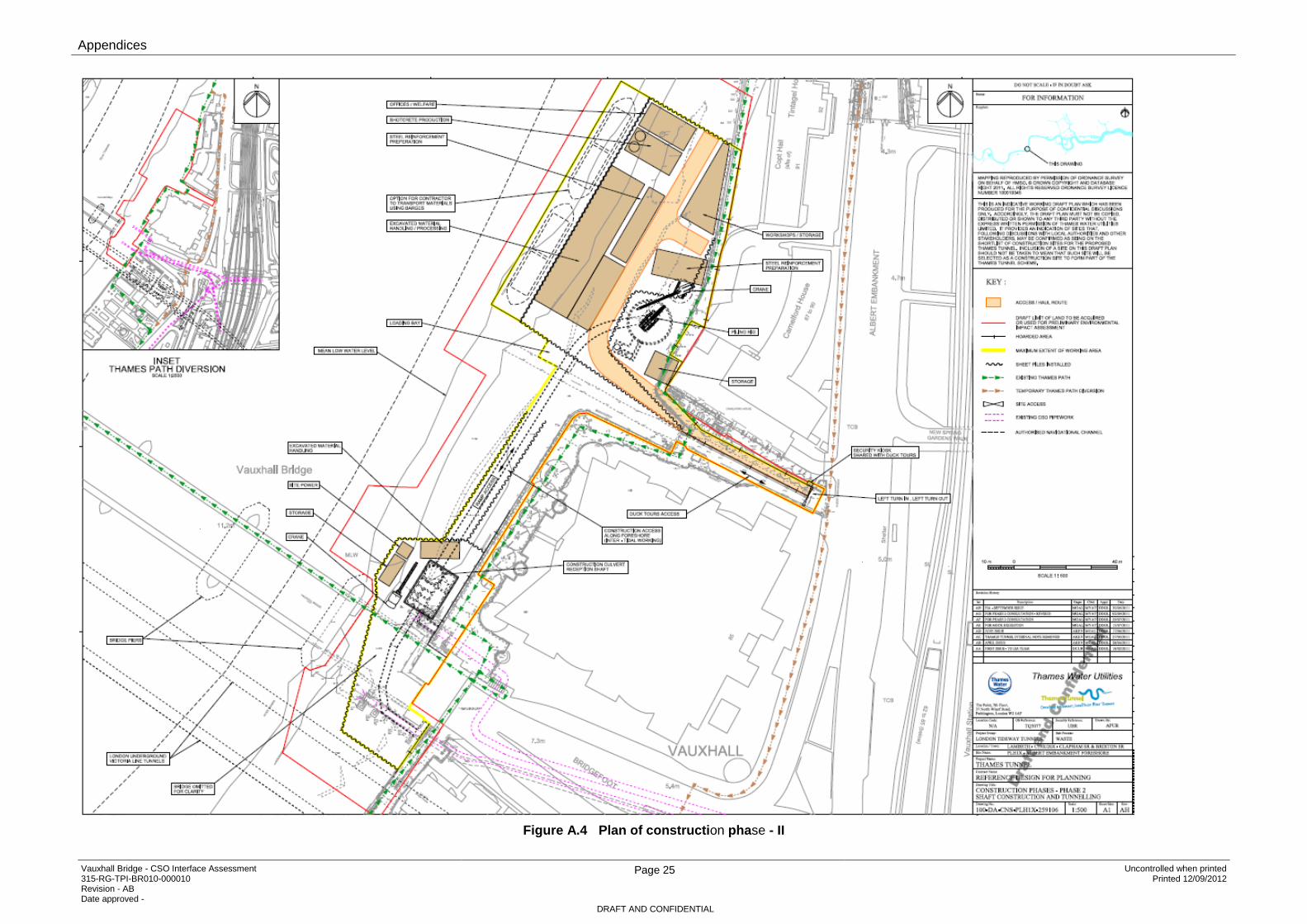
Figure A.4 Plan of construction phase - II

Appendices
Vauxhall Bridge - CSO Interface Assessment 315-RG-TPI-BR010-000010 Revision - AB Date approved -
Page 26 Uncontrolled when printed Printed 12/09/2012
DRAFT AND CONFIDENTIAL
Figure A.5 Plan of Construction phase-Temporary spillway

Appendices
Vauxhall Bridge - CSO Interface Assessment 315-RG-TPI-BR010-000010 Revision - AB Date approved -
Page 27 Uncontrolled when printed Printed 12/09/2012
DRAFT AND CONFIDENTIAL
Figure A.6 Plan of Interception Chamber

Appendices
Vauxhall Bridge - CSO Interface Assessment 315-RG-TPI-BR010-000010 Revision - AB Date approved -
Page 28 Uncontrolled when printed Printed 12/09/2012
DRAFT AND CONFIDENTIAL
Figure A.7 Plan of Shaft at Ground Level

Appendices
Vauxhall Bridge - CSO Interface Assessment 315-RG-TPI-BR010-000010 Revision - AB Date approved -
Page 29 Uncontrolled when printed Printed 12/09/2012
DRAFT AND CONFIDENTIAL
Figure A.8 Sections of Shaft and Connecting Culvert

Appendices
Vauxhall Bridge - CSO Interface Assessment 315-RG-TPI-BR010-000010 Revision - AB Date approved -
Page 30 Uncontrolled when printed Printed 12/09/2012
DRAFT AND CONFIDENTIAL
Appendix B – Geotechnical Assessment Report

CSO_Works_Vauxhall_Bridge_Report.docx
1. Introduction
Atkins Tunnelling and Substructures have been asked by Atkins Highways and Transportation to assess the impact of the Thames Tunnel CSO Works and associated structures on the Albert Embankment foreshore at Vauxhall Bridge. The bridge pier and abutment are assessed for any effects arising during the demolition, construction and permanent phases. The ground movements generated during each phase are assessed in this report.
The “Combined Sewer Overflow” works and associated structures on the Albert Embankment foreshore at Vauxhall Bridge include the installation and removal of temporary sheet piling below, upstream and downstream of the first span of the bridge, the construction of a Connection Culvert and Culvert Reception Shaft with storm overflow, and embankment reconstruction with terracing.
The Bridge sits on four piers and two river wall abutments. The CSO works will affect mainly the Pier and river wall Abutment at the south river bank at Vauxhall Bridge. Therefore, the ground movements generated at the foundation footings of just these two parts of the bridge are assessed in this report.
Figure 1: CSO Works on the Albert Embankment foreshore at Vauxhall Bridge.

CSO_Works_Vauxhall_Bridge_Report.docx
2. Reference Information
The reference information used in the assessment is provided by Thames Tunnel and normal assumptions have been made to cover any further data, necessary to carry out a complete analysis. The parameters used in the assessment are presented in the table below:
Parameters Values
Culvert Reception Shaft dimensions 13.0m x 20.0m
Approximate Cofferdam excavation area 2700 m2
Approximate river bed level 99.000mATD
Excavation level - Culvert Reception Shaft (Thames Tunnel, 2011) 15.3
Depth level - Culvert Reception Shaft (Thames Tunnel, 2011) 84.200mATD
Final Construction level (Thames Tunnel, 2011) 104.600mATD
Table 1: CSO Works assessment parameters
Figure 2: Cross section of CSO Works.

CSO_Works_Vauxhall_Bridge_Report.docx
2.1. Calculation Phases
The construction phases considered in the assessment of ground movement are as described by Thames Tunnel, and normal assumptions regarding the calculation phases.
The calculation phases considered are six, and they represent the “CSO” works:
1. Installation of the temporary sheet pile walls under the south span of the bridge and dredging of 1.0m to 1.5m of the river bed inside the cofferdam;
2. Secant pile installation for the Culvert Reception Shaft construction;
3. Movement behind the secant piles due to excavation of the Culvert Reception Shaft;
4. Heave due to the excavation of the Culvert reception Shaft;
5. Short term movements due to Embankment reconstruction;
6. Long term settlements due to the Embankment reconstruction.
These construction phases are considered in the pier and abutment footing assessment of Vauxhall Bridge.

CSO_Works_Vauxhall_Bridge_Report.docx
2.2. Modelling of CSO Works
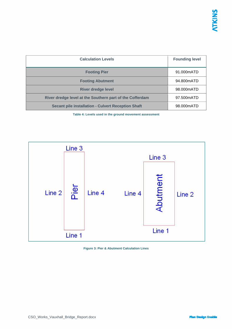
Ground movements that affect the Albert Embankment foreshore at Vauxhall Bridge due to the CSO Works have been estimated along lines defining the perimeter of the pier and abutment foundations. The loading and unloading of the Bridge foundations at each construction phase is modelled by load areas. The Culvert Reception Shaft construction is modelled by an embedded wall excavation, defined by a polygon describing its plan area, top and bottom levels, and its associated vertical and horizontal ground movement curves.
Each line of the pier and abutment foundation has been divided into intervals of around 1.0m length to obtain a better deformation shape of the footing perimeter, although the exact dimensions and subdivision of the foundations is not clear from the historical drawings of Vauxhall Bridge provided by Thames Tunnel.
The ground movements have been assessed at each construction phase of the CSO Works for the perimeter of the pier and abutment foundation level. The settlement analysis is carried out by the input of linear elastic parameters for the soil layers at the proposed CSO works location. The levels of the stratum are provided by Thames Tunnel, and the two soil layers of interest to the analysis are the river terrace deposits and the London clay. The geotechnical parameters used in the calculation are the Poissons ratio and Elastic modulus, which is considered to vary linearly with depth for the London clay. The assessment of the long term effects on the London clay layer are considered by the input of the drained elastic modulus (E’). The other construction phases are analysed by the undrained elastic modulus (Eu). The geotechnical parameters assigned to the analysis are estimates from previous projects in the nearby area. The British Geological Survey borehole record did not generally include in situ testing in the London clay layer to obtain significant parameters, and the few values did not indicate a clear trend for predicting the increase of stiffness with depth in the London clay. The geotechnical parameters used in the analysis model are assigned in the below table.
Layer Description Level at top
[m ATD] Young's modulus [kPa] Poisson's
ratio Top Bottom
1 River Terrace
Deposits 99.00 30000 30000 0.3
2 London Clay 95.00 75000 160000 0.2
Table 2: Short term geotechnical parameters
Layer Description Level at top
[m ATD] Young's modulus [kPa] Poisson's
ratio Top Bottom
1 River Terrace
Deposits 99.00 30000 30000 0.3
2 London Clay 95.00 60000 128000 0.2
Table 3: Long term geotechnical parameters
CSO_Works_Vauxhall_Bridge_Report.docx
Calculation Levels Founding level
Footing Pier 91.000mATD
Footing Abutment 94.800mATD
River dredge level 98.000mATD
River dredge level at the Southern part of the Cofferdam 97.500mATD
Secant pile installation - Culvert Reception Shaft 98.000mATD
Table 4: Levels used in the ground movement assessment
Figure 3: Pier & Abutment Calculation Lines
CSO_Works_Vauxhall_Bridge_Report.docx
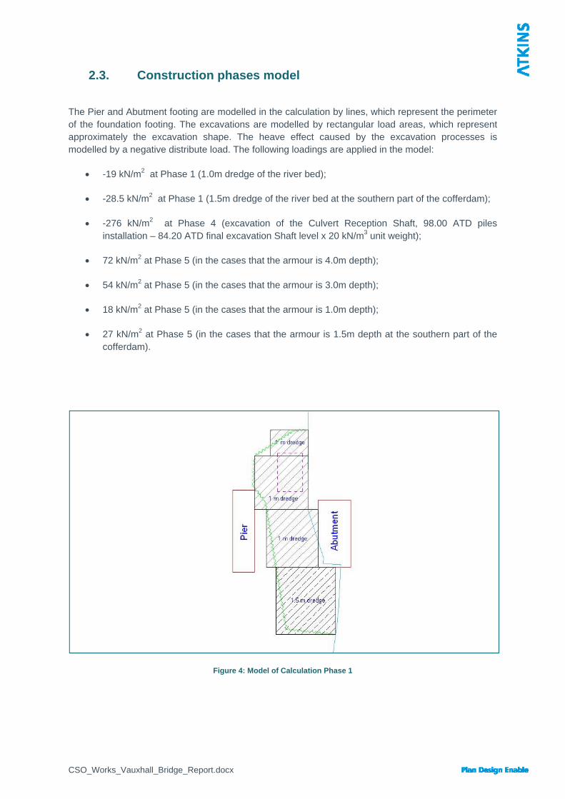
2.3. Construction phases model
The Pier and Abutment footing are modelled in the calculation by lines, which represent the perimeter of the foundation footing. The excavations are modelled by rectangular load areas, which represent approximately the excavation shape. The heave effect caused by the excavation processes is modelled by a negative distribute load. The following loadings are applied in the model:
-19 kN/m2 at Phase 1 (1.0m dredge of the river bed);
-28.5 kN/m2 at Phase 1 (1.5m dredge of the river bed at the southern part of the cofferdam);
-276 kN/m2 at Phase 4 (excavation of the Culvert Reception Shaft, 98.00 ATD piles installation – 84.20 ATD final excavation Shaft level x 20 kN/m3 unit weight);
72 kN/m2 at Phase 5 (in the cases that the armour is 4.0m depth);
54 kN/m2 at Phase 5 (in the cases that the armour is 3.0m depth);
18 kN/m2 at Phase 5 (in the cases that the armour is 1.0m depth);
27 kN/m2 at Phase 5 (in the cases that the armour is 1.5m depth at the southern part of the cofferdam).
Figure 4: Model of Calculation Phase 1

CSO_Works_Vauxhall_Bridge_Report.docx
Figure 5: Model of Calculation Phase 2, 3, & 4
Figure 6: Model of Calculation Phase 5 & 6.

CSO_Works_Vauxhall_Bridge_Report.docx
3. Methodology The effects of the CSO works on the pier and abutment foundation on the Albert Foreshore Embankment at Vauxhall Bridge are estimated by two different software programmes. Construction phase 1, 4, 5 and 6 are analysed by the software “Vdisp” of Oasys, which calculates the settlements within a linear or non linear soil mass. Vdisp uses the Boussinesq (1985) analysis method for the displacements estimation. Phase 2 and 3 are analysed by the software “Xdisp” of Oasys, which calculates the ground movements induced by an embedded wall excavation. The method used by Xdisp to estimate the ground movements beside an embedded retaining wall is the proposed method in the CIRIA Report C580. It calculates movements due to the installation of an embedded wall and due to excavation in front of the embedded wall.
3.1. Assumptions
i. The geotechnical data used in the analysis is considered from previous projects in the nearby area;
ii. The general layout of the project and the calculation levels are provided by Thames Tunnel drawings and reports;
iii. It is assumed in the calculations that in Phase 1 after the installation of the temporary sheet pile wall there would be a 1.0m to 1.5m dredge of the river bed;
iv. The Embankment construction at Phase 5 will use crushed stone of 18 kN/m3 unit weight to form protective terraces;
v. The Culvert Reception Shaft construction in Phase 2 is assumed to be done by the Installation of secant bored pile wall in stiff clay (CIRIA 580 Fig. 2.8(a));
vi. The Culvert Reception Shaft excavation in Phase 3 is modelled as excavation in front of a high stiffness wall in stiff clay (CIRIA 580 Fig. 2.11(a));
vii. The vertical ground movements (settlements) generated by each calculation phase are analysed, plus the horizontal movements in Phase 2 and 3;
viii. The Thames River tidal level is considered in the calculations not to affect the cofferdams, and the excavated clay is assumed to have a bulk unit weight;
ix. The tidal cycle effect in the cofferdam area will not generate any overpore pressure in the London Clay;
x. The Short term settlement profile at Phase 5 is obtained by adding to Phase 5 the contribution of the previous calculations;
xi. The Long term settlement profile at Phase 6 is obtained by adding to Phase 6 the contribution of the previous calculations, except Phase 5;
xii. It is assumed in V-disp analysis a rigid boundary at 0.00 m ATD.

CSO_Works_Vauxhall_Bridge_Report.docx
3.2. Analysis and Results
Each calculation has been divided into intervals of around 1.0m length; this will give the ground movements for the Pier and the Abutment.
In the analysis vertical ground movements are shown as positive if they are settlements (S), while heave effects are shown as negative.
The ground movements for each line have been calculated for each progressive calculation phase. The displacements of the calculation lines change for each of the 6 phases of the CSO Works construction.
The horizontal movements are considered just for phase 2 & 3 of the calculations. The horizontal displacements direction is shown in Figure 7.
Figure 7: Direction of horizontal movements.

CSO_Works_Vauxhall_Bridge_Report.docx
3.2.1. Pier
3.2.1.1. Settlement Graphs (S)
Figure 8: Settlement of Line 1
Figure 9: Settlement of Line 2
Note: Phase 1, 2, 3, and 4 are individual calculations; Phase 5 & 6 are the short term and long term profiles (see paragraph 3.1).

CSO_Works_Vauxhall_Bridge_Report.docx
Figure 10: Settlement of Line 3
Figure 11: Settlement of Line 4
Note: Phase 1, 2, 3, and 4 are individual calculations; Phase 5 & 6 are the short term and long term profiles (see paragraph 3.1).

CSO_Works_Vauxhall_Bridge_Report.docx
3.2.1.2. Horizontal Movement (X)
Figure 12: Horizontal Movements (X) of Line 2.
Figure 13: Horizontal Movements (X) of Line 3.

CSO_Works_Vauxhall_Bridge_Report.docx
Figure 14: Horizontal Movements (X) of Line 4.
3.2.1.3. Horizontal Movement (Y)
Figure 15: Horizontal Movements (Y) of Line 2.

CSO_Works_Vauxhall_Bridge_Report.docx
Figure 16: Horizontal Movements (Y) of Line 4.

CSO_Works_Vauxhall_Bridge_Report.docx
3.2.2. Abutment
3.2.2.1. Settlement Graphs (S)
Figure 17: Settlement of Line 1
Figure 18: Settlement of Line 2
Note: Phase 1, 2, 3, and 4 are individual calculations; Phase 5 & 6 are the short term and long term profiles (see paragraph 3.1).

CSO_Works_Vauxhall_Bridge_Report.docx
Figure 19: Settlement of Line 3
Figure 20: Settlement of Line 4
Note: Phase 1, 2, 3, and 4 are individual calculations; Phase 5 & 6 are the short term and long term profiles (see paragraph 3.1).

CSO_Works_Vauxhall_Bridge_Report.docx
3.2.2.2. Horizontal Movement (X)
Figure 21: Horizontal Movements (X) of Line 1.
Figure 22: Horizontal Movements (X) of Line 2.
CSO_Works_Vauxhall_Bridge_Report.docx
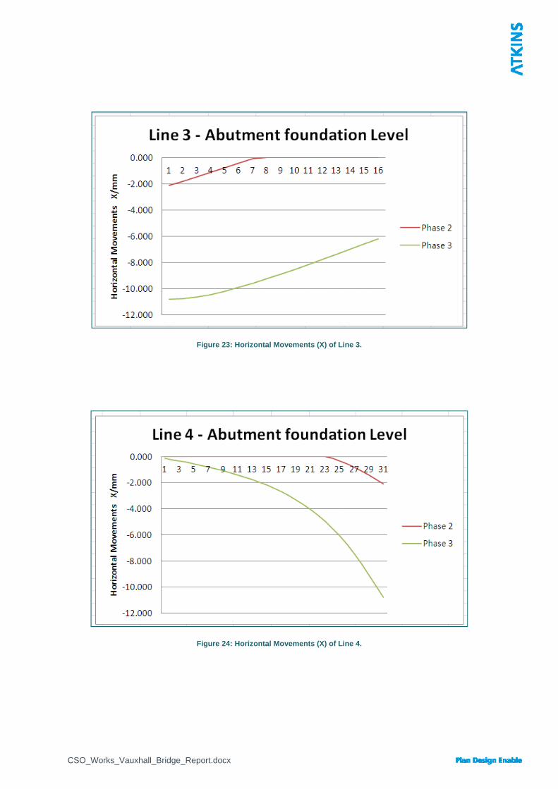
Figure 23: Horizontal Movements (X) of Line 3.
Figure 24: Horizontal Movements (X) of Line 4.

CSO_Works_Vauxhall_Bridge_Report.docx
3.2.2.3. Horizontal Movement (Y)
Figure 25: Horizontal Movements (Y) of Line 1.
Figure 26: Horizontal Movements (Y) of Line 2.

CSO_Works_Vauxhall_Bridge_Report.docx
Figure 27: Horizontal Movements (Y) of Line 3.
Figure 28: Horizontal Movements (Y) of Line 4.

CSO_Works_Vauxhall_Bridge_Report.docx
4. Results Tables
Line 1 - Pier Line 3 - Pier S/mm Phase 1 Phase 2 Phase 3 Phase 4 Phase 5 Phase 6 S/mm Phase 1 Phase 2 Phase 3 Phase 4 Phase 5 Phase 6
0.00 -1.275 0.000 0.000 -0.429 0.072 0.536 0.00 -1.364 0.000 0.229 -2.121 -1.109 -0.549 1.13 -1.343 0.000 0.000 -0.442 0.083 0.570 1.13 -1.450 0.000 0.320 -2.269 -1.119 -0.524 2.26 -1.415 0.000 0.000 -0.454 0.097 0.609 2.26 -1.544 0.000 0.453 -2.430 -1.095 -0.464 3.38 -1.492 0.000 0.000 -0.467 0.111 0.650 3.38 -1.647 0.000 0.634 -2.603 -1.032 -0.361 4.51 -1.575 0.000 0.000 -0.479 0.127 0.694 4.51 -1.761 0.000 0.869 -2.793 -0.927 -0.214 5.64 -1.663 0.000 0.000 -0.492 0.144 0.741 5.64 -1.886 0.000 1.158 -3.001 -0.780 -0.021 6.77 -1.758 0.000 0.000 -0.504 0.163 0.792 6.77 -2.024 0.000 1.499 -3.227 -0.594 0.216 7.90 -1.860 0.000 0.000 -0.516 0.185 0.848 7.90 -2.175 0.000 1.887 -3.476 -0.375 0.488 9.02 -1.970 0.000 0.000 -0.527 0.209 0.910 9.02 -2.337 0.000 2.312 -3.746 -0.130 0.790
10.15 -2.089 0.000 0.000 -0.539 0.235 0.975 10.15 -2.509 0.283 2.763 -4.047 0.404 1.384 11.28 -2.218 0.000 0.000 -0.550 0.265 1.047 11.28 -2.686 0.565 3.225 -4.380 0.931 1.970
Line 2 - Pier Line 4 - Pier S/mm Phase 1 Phase 2 Phase 3 Phase 4 Phase 5 Phase 6 S/mm Phase 1 Phase 2 Phase 3 Phase 4 Phase 5 Phase 6
0.00 -1.275 0.000 0.000 -0.429 0.072 0.536 0.00 -2.218 0.000 0.000 -0.550 0.265 1.047 1.43 -1.285 0.000 0.000 -0.458 0.061 0.532 1.43 -2.239 0.000 0.000 -0.591 0.254 1.050 2.86 -1.295 0.000 0.000 -0.489 0.048 0.526 2.86 -2.259 0.000 0.000 -0.635 0.239 1.048 4.29 -1.304 0.000 0.000 -0.521 0.032 0.517 4.29 -2.279 0.000 0.000 -0.682 0.219 1.039 5.72 -1.312 0.000 0.000 -0.555 0.015 0.507 5.72 -2.296 0.000 0.000 -0.733 0.195 1.027 7.15 -1.319 0.000 0.000 -0.592 -0.005 0.493 7.15 -2.310 0.000 0.000 -0.788 0.168 1.011 8.58 -1.326 0.000 0.000 -0.631 -0.029 0.475 8.58 -2.323 0.000 0.000 -0.847 0.136 0.990
10.01 -1.332 0.000 0.000 -0.672 -0.054 0.456 10.01 -2.332 0.000 0.000 -0.911 0.102 0.965 11.44 -1.338 0.000 0.000 -0.715 -0.082 0.433 11.44 -2.340 0.000 0.000 -0.980 0.062 0.936 12.87 -1.343 0.000 0.000 -0.761 -0.114 0.406 12.87 -2.347 0.000 0.000 -1.053 0.019 0.902 14.30 -1.347 0.000 0.000 -0.809 -0.147 0.378 14.30 -2.352 0.000 0.000 -1.133 -0.029 0.863 15.73 -1.352 0.000 0.000 -0.860 -0.185 0.344 15.73 -2.356 0.000 0.000 -1.219 -0.083 0.819 17.16 -1.356 0.000 0.000 -0.913 -0.226 0.309 17.16 -2.360 0.000 0.000 -1.311 -0.142 0.769 18.59 -1.359 0.000 0.000 -0.969 -0.269 0.270 18.59 -2.365 0.000 0.064 -1.411 -0.146 0.774 20.02 -1.363 0.000 0.000 -1.028 -0.317 0.225 20.02 -2.370 0.000 0.119 -1.518 -0.166 0.764 21.45 -1.367 0.000 0.000 -1.089 -0.368 0.178 21.45 -2.377 0.000 0.168 -1.633 -0.203 0.736 22.88 -1.370 0.000 0.000 -1.152 -0.421 0.128 22.88 -2.385 0.000 0.235 -1.757 -0.232 0.716 24.31 -1.374 0.000 0.000 -1.218 -0.479 0.073 24.31 -2.397 0.000 0.338 -1.890 -0.239 0.718 25.74 -1.377 0.000 0.000 -1.286 -0.539 0.016 25.74 -2.412 0.000 0.487 -2.033 -0.213 0.752 27.17 -1.381 0.000 0.000 -1.357 -0.604 -0.046 27.17 -2.433 0.000 0.684 -2.186 -0.156 0.817 28.60 -1.384 0.000 0.053 -1.428 -0.616 -0.056 28.60 -2.459 0.000 0.928 -2.349 -0.066 0.915 30.03 -1.387 0.000 0.088 -1.502 -0.651 -0.089 30.03 -2.493 0.000 1.213 -2.523 0.046 1.036 31.46 -1.390 0.000 0.114 -1.576 -0.695 -0.131 31.46 -2.532 0.000 1.525 -2.708 0.171 1.168 32.89 -1.392 0.000 0.136 -1.650 -0.744 -0.179 32.89 -2.574 0.000 1.851 -2.902 0.298 1.303 34.32 -1.393 0.000 0.156 -1.724 -0.795 -0.229 34.32 -2.614 0.000 2.174 -3.106 0.415 1.427 35.75 -1.392 0.000 0.175 -1.797 -0.846 -0.280 35.75 -2.648 0.105 2.477 -3.317 0.617 1.636 37.18 -1.390 0.000 0.193 -1.869 -0.898 -0.331 37.18 -2.674 0.271 2.744 -3.534 0.846 1.872 38.61 -1.387 0.000 0.209 -1.938 -0.949 -0.383 38.61 -2.689 0.404 2.961 -3.754 1.003 2.033 40.04 -1.381 0.000 0.220 -2.004 -1.002 -0.437 40.04 -2.696 0.499 3.117 -3.972 1.074 2.109 41.47 -1.374 0.000 0.227 -2.065 -1.056 -0.492 41.47 -2.696 0.553 3.205 -4.183 1.050 2.088 42.90 -1.364 0.000 0.229 -2.121 -1.109 -0.549 42.90 -2.688 0.565 3.225 -4.384 0.928 1.968
Table 5: Results Pier foundation level - Settlements Note: positive values for “S” are settlements.

CSO_Works_Vauxhall_Bridge_Report.docx
Line 1 - Abutment Line 3 - Abutment S/mm Phase 1 Phase 2 Phase 3 Phase 4 Phase 5 Phase 6 S/mm Phase 1 Phase 2 Phase 3 Phase 4 Phase 5 Phase 6
0.00 -5.079 0.000 0.125 -0.658 4.738 7.328 0.00 -2.500 2.955 7.625 -4.329 8.698 9.935 1.14 -4.870 0.000 0.114 -0.646 4.578 7.068 1.14 -2.343 2.703 7.465 -4.043 8.384 9.535 2.28 -4.662 0.000 0.100 -0.634 4.404 6.804 2.28 -2.202 2.446 7.237 -3.778 8.000 9.075 3.41 -4.458 0.000 0.083 -0.621 4.231 6.535 3.41 -2.074 2.183 6.950 -3.534 7.551 8.558 4.55 -4.253 0.000 0.064 -0.607 4.061 6.273 4.55 -1.958 1.917 6.612 -3.305 7.049 7.994 5.69 -4.037 0.000 0.040 -0.593 3.894 6.019 5.69 -1.851 1.648 6.234 -3.093 6.501 7.392 6.83 -3.803 0.000 0.011 -0.579 3.724 5.749 6.83 -1.753 1.377 5.824 -2.895 5.916 6.757 7.97 -3.544 0.000 0.000 -0.565 3.566 5.485 7.97 -1.662 1.105 5.391 -2.712 5.303 6.098 9.10 -3.265 0.000 0.000 -0.550 3.398 5.202 9.10 -1.578 0.830 4.945 -2.543 4.667 5.420
10.24 -2.987 0.000 0.000 -0.536 3.181 4.857 10.24 -1.500 0.555 4.494 -2.384 4.022 4.736 11.38 -2.736 0.000 0.000 -0.521 2.901 4.440 11.38 -1.427 0.278 4.044 -2.236 3.373 4.052 12.52 -2.519 0.000 0.000 -0.506 2.580 3.981 12.52 -1.359 0.001 3.604 -2.098 2.727 3.372 13.66 -2.332 0.000 0.000 -0.491 2.262 3.533 13.66 -1.295 0.000 3.178 -1.970 2.366 2.980 14.79 -2.169 0.000 0.000 -0.476 1.977 3.132 14.79 -1.234 0.000 2.773 -1.851 2.024 2.608 15.93 -2.026 0.000 0.000 -0.461 1.733 2.788 15.93 -1.177 0.000 2.393 -1.739 1.702 2.258 17.07 -1.897 0.000 0.000 -0.447 1.530 2.498 17.07 -1.123 0.000 2.041 -1.634 1.404 1.934
Line 2 - Abutment Line 4 - Abutment S/mm Phase 1 Phase 2 Phase 3 Phase 4 Phase 5 Phase 6 S/mm Phase 1 Phase 2 Phase 3 Phase 4 Phase 5 Phase 6
0.00 -1.897 0.000 0.000 -0.447 1.530 2.498 0.00 -5.079 0.000 0.125 -0.658 4.738 7.328 1.17 -1.860 0.000 0.000 -0.470 1.450 2.395 1.17 -4.827 0.000 0.173 -0.699 4.583 7.066 2.33 -1.823 0.000 0.000 -0.495 1.366 2.287 2.33 -4.607 0.000 0.215 -0.742 4.419 6.806 3.50 -1.786 0.000 0.000 -0.520 1.282 2.178 3.50 -4.428 0.000 0.261 -0.789 4.271 6.574 4.67 -1.750 0.000 0.000 -0.547 1.199 2.073 4.67 -4.285 0.000 0.318 -0.838 4.156 6.395 5.84 -1.714 0.000 0.026 -0.575 1.146 1.998 5.84 -4.168 0.000 0.391 -0.891 4.075 6.262 7.00 -1.680 0.000 0.086 -0.605 1.129 1.961 7.00 -4.072 0.000 0.487 -0.947 4.032 6.168 8.17 -1.648 0.000 0.131 -0.635 1.101 1.914 8.17 -3.990 0.000 0.608 -1.007 4.024 6.131 9.34 -1.617 0.000 0.168 -0.667 1.067 1.863 9.34 -3.919 0.000 0.759 -1.071 4.051 6.119
10.51 -1.587 0.000 0.202 -0.700 1.032 1.811 10.51 -3.857 0.000 0.942 -1.139 4.110 6.156 11.67 -1.559 0.000 0.235 -0.735 0.998 1.762 11.67 -3.801 0.000 1.157 -1.211 4.200 6.215 12.84 -1.532 0.000 0.272 -0.771 0.967 1.717 12.84 -3.751 0.000 1.407 -1.289 4.315 6.302 14.01 -1.505 0.000 0.314 -0.808 0.945 1.681 14.01 -3.704 0.000 1.689 -1.372 4.452 6.412 15.18 -1.480 0.000 0.365 -0.847 0.928 1.651 15.18 -3.661 0.000 2.003 -1.461 4.602 6.533 16.34 -1.456 0.000 0.424 -0.886 0.921 1.631 16.34 -3.619 0.000 2.347 -1.555 4.765 6.663 17.51 -1.432 0.000 0.494 -0.927 0.924 1.621 17.51 -3.579 0.000 2.718 -1.657 4.935 6.799 18.68 -1.409 0.000 0.573 -0.970 0.936 1.621 18.68 -3.539 0.000 3.111 -1.766 5.119 6.947 19.85 -1.387 0.000 0.662 -1.013 0.957 1.630 19.85 -3.499 0.000 3.522 -1.881 5.322 7.117 21.01 -1.365 0.000 0.760 -1.058 0.985 1.647 21.01 -3.458 0.217 3.946 -2.005 5.755 7.519 22.18 -1.343 0.000 0.867 -1.104 1.023 1.673 22.18 -3.415 0.483 4.376 -2.139 6.240 7.974 23.35 -1.322 0.000 0.980 -1.151 1.065 1.704 23.35 -3.368 0.746 4.806 -2.282 6.715 8.418 24.51 -1.301 0.000 1.097 -1.198 1.111 1.739 24.51 -3.316 1.004 5.229 -2.433 7.168 8.839 25.68 -1.280 0.000 1.218 -1.247 1.159 1.776 25.68 -3.256 1.259 5.637 -2.596 7.585 9.220 26.85 -1.260 0.000 1.340 -1.296 1.208 1.814 26.85 -3.185 1.508 6.024 -2.771 7.952 9.546 28.02 -1.240 0.000 1.461 -1.345 1.256 1.851 28.02 -3.097 1.750 6.381 -2.957 8.265 9.812 29.18 -1.220 0.000 1.578 -1.394 1.300 1.884 29.18 -2.990 1.985 6.702 -3.154 8.516 10.010 30.35 -1.200 0.000 1.689 -1.443 1.338 1.911 30.35 -2.869 2.209 6.981 -3.365 8.701 10.137 31.52 -1.180 0.000 1.793 -1.492 1.370 1.932 31.52 -2.750 2.422 7.213 -3.589 8.814 10.193 32.69 -1.161 0.000 1.888 -1.540 1.392 1.944 32.69 -2.648 2.619 7.397 -3.824 8.851 10.177 33.85 -1.142 0.000 1.971 -1.587 1.404 1.945 33.85 -2.566 2.798 7.533 -4.069 8.812 10.091 35.02 -1.123 0.000 2.041 -1.633 1.405 1.934 35.02 -2.499 2.955 7.625 -4.326 8.699 9.934
Table 6: Results Abutment foundation level - Settlements Note: positive values for “S” are settlements.

CSO_Works_Vauxhall_Bridge_Report.docx
Line 1 - Pier Line 3 - Pier Line 1 - Pier Line 3 - Pier X/mm Phase 2 Phase 3 X/mm Phase 2 Phase 3 Y/mm Phase 2 Phase 3 Y/mm Phase 2 Phase 3
0.00 0.000 0.000 0.00 0.000 1.718 0.00 0.000 0.000 0.00 0.000 0.000 1.13 0.000 0.000 1.13 0.000 2.141 1.13 0.000 0.000 1.13 0.000 0.000 2.26 0.000 0.000 2.26 0.000 2.564 2.26 0.000 0.000 2.26 0.000 0.000 3.38 0.000 0.000 3.38 0.000 2.987 3.38 0.000 0.000 3.38 0.000 0.000 4.51 0.000 0.000 4.51 0.000 3.410 4.51 0.000 0.000 4.51 0.000 0.000 5.64 0.000 0.000 5.64 0.000 3.833 5.64 0.000 0.000 5.64 0.000 0.000 6.77 0.000 0.000 6.77 0.000 4.256 6.77 0.000 0.000 6.77 0.000 0.000 7.90 0.000 0.000 7.90 0.000 4.679 7.90 0.000 0.000 7.90 0.000 0.000 9.02 0.000 0.000 9.02 0.000 5.102 9.02 0.000 0.000 9.02 0.000 0.000
10.15 0.000 0.000 10.15 0.000 5.525 10.15 0.000 0.000 10.15 0.000 0.000 11.28 0.000 0.000 11.28 0.000 5.948 11.28 0.000 0.000 11.28 0.000 0.000 Line 2 - Pier Line 4 - Pier Line 2 - Pier Line 4 - Pier X/mm Phase 2 Phase 3 X/mm Phase 2 Phase 3 Y/mm Phase 2 Phase 3 Y/mm Phase 2 Phase 3
0.00 0.000 0.000 0.00 0.000 0.000 0.00 0.000 0.000 0.00 0.000 0.000 1.43 0.000 0.000 1.43 0.000 0.000 1.43 0.000 0.000 1.43 0.000 0.000 2.86 0.000 0.000 2.86 0.000 0.000 2.86 0.000 0.000 2.86 0.000 0.000 4.29 0.000 0.000 4.29 0.000 0.000 4.29 0.000 0.000 4.29 0.000 0.000 5.72 0.000 0.000 5.72 0.000 0.000 5.72 0.000 0.000 5.72 0.000 0.000 7.15 0.000 0.000 7.15 0.000 0.000 7.15 0.000 0.000 7.15 0.000 0.000 8.58 0.000 0.000 8.58 0.000 0.000 8.58 0.000 0.000 8.58 0.000 0.000
10.01 0.000 0.000 10.01 0.000 0.000 10.01 0.000 0.000 10.01 0.000 0.000 11.44 0.000 0.000 11.44 0.000 0.000 11.44 0.000 0.000 11.44 0.000 0.000 12.87 0.000 0.000 12.87 0.000 0.000 12.87 0.000 0.000 12.87 0.000 0.000 14.30 0.000 0.000 14.30 0.000 0.000 14.30 0.000 0.000 14.30 0.000 0.000 15.73 0.000 0.000 15.73 0.000 0.000 15.73 0.000 0.000 15.73 0.000 0.000 17.16 0.000 0.000 17.16 0.000 0.000 17.16 0.000 0.000 17.16 0.000 0.000 18.59 0.000 0.000 18.59 0.000 0.148 18.59 0.000 0.000 18.59 0.000 0.309 20.02 0.000 0.000 20.02 0.000 0.371 20.02 0.000 0.000 20.02 0.000 0.730 21.45 0.000 0.000 21.45 0.000 0.616 21.45 0.000 0.000 21.45 0.000 1.133 22.88 0.000 0.000 22.88 0.000 0.882 22.88 0.000 0.000 22.88 0.000 1.515 24.31 0.000 0.000 24.31 0.000 1.174 24.31 0.000 0.000 24.31 0.000 1.869 25.74 0.000 0.000 25.74 0.000 1.494 25.74 0.000 0.000 25.74 0.000 2.191 27.17 0.000 0.000 27.17 0.000 1.843 27.17 0.000 0.000 27.17 0.000 2.473 28.60 0.000 0.226 28.60 0.000 2.224 28.60 0.000 0.138 28.60 0.000 2.706 30.03 0.000 0.465 30.03 0.000 2.637 30.03 0.000 0.255 30.03 0.000 2.879 31.46 0.000 0.696 31.46 0.000 3.081 31.46 0.000 0.337 31.46 0.000 2.978 32.89 0.000 0.915 32.89 0.000 3.551 32.89 0.000 0.386 32.89 0.000 2.989 34.32 0.000 1.116 34.32 0.000 4.037 34.32 0.000 0.401 34.32 0.000 2.894 35.75 0.000 1.296 35.75 0.000 4.525 35.75 0.000 0.385 35.75 0.000 2.679 37.18 0.000 1.449 37.18 0.000 4.989 37.18 0.000 0.339 37.18 0.000 2.330 38.61 0.000 1.571 38.61 0.000 5.398 38.61 0.000 0.269 38.61 0.000 1.847 40.04 0.000 1.658 40.04 0.000 5.715 40.04 0.000 0.181 40.04 0.000 1.242 41.47 0.000 1.707 41.47 0.000 5.904 41.47 0.000 0.079 41.47 0.000 0.545 42.90 0.000 1.718 42.90 0.000 5.948 42.90 0.000 0.000 42.90 0.000 0.000
Table 7: Results Pier foundation level – Horizontal Movements

CSO_Works_Vauxhall_Bridge_Report.docx
Line 1 - Abutment Line 3 - Abutment Line 1 - Abutment Line 3 - Abutment X/mm Phase 2 Phase 3 X/mm Phase 2 Phase 3 Y/mm Phase 2 Phase 3 Y/mm Phase 2 Phase 3
0.00 0.000 -0.147 0.00 -2.113 -10.784 0.00 0.000 0.711 0.00 1.192 6.085 1.14 0.000 -0.145 1.14 -1.799 -10.758 1.14 0.000 0.618 1.14 0.891 5.328 2.28 0.000 -0.135 2.28 -1.468 -10.629 2.28 0.000 0.514 2.28 0.648 4.691 3.41 0.000 -0.117 3.41 -1.128 -10.429 3.41 0.000 0.400 3.41 0.449 4.150 4.55 0.000 -0.089 4.55 -0.783 -10.178 4.55 0.000 0.278 4.55 0.284 3.688 5.69 0.000 -0.052 5.69 -0.432 -9.890 5.69 0.000 0.147 5.69 0.144 3.290 6.83 0.000 -0.004 6.83 -0.072 -9.574 6.83 0.000 0.009 6.83 0.022 2.943 7.97 0.000 0.000 7.97 0.000 -9.237 7.97 0.000 0.000 7.97 0.000 2.639 9.10 0.000 0.000 9.10 0.000 -8.885 9.10 0.000 0.000 9.10 0.000 2.371
10.24 0.000 0.000 10.24 0.000 -8.519 10.24 0.000 0.000 10.24 0.000 2.133 11.38 0.000 0.000 11.38 0.000 -8.144 11.38 0.000 0.000 11.38 0.000 1.921 12.52 0.000 0.000 12.52 0.000 -7.761 12.52 0.000 0.000 12.52 0.000 1.730 13.66 0.000 0.000 13.66 0.000 -7.372 13.66 0.000 0.000 13.66 0.000 1.557 14.79 0.000 0.000 14.79 0.000 -6.978 14.79 0.000 0.000 14.79 0.000 1.401 15.93 0.000 0.000 15.93 0.000 -6.579 15.93 0.000 0.000 15.93 0.000 1.258 17.07 0.000 0.000 17.07 0.000 -6.176 17.07 0.000 0.000 17.07 0.000 1.128
Line 2 - Abutment Line 4 - Abutment Line 2 - Abutment Line 4 - Abutment X/mm Phase 2 Phase 3 X/mm Phase 2 Phase 3 Y/mm Phase 2 Phase 3 Y/mm Phase 2 Phase 3
0.00 0.000 0.000 0.00 0.000 -0.147 0.00 0.000 0.000 0.00 0.000 0.711 1.17 0.000 0.000 1.17 0.000 -0.240 1.17 0.000 0.000 1.17 0.000 1.130 2.33 0.000 0.000 2.33 0.000 -0.339 2.33 0.000 0.000 2.33 0.000 1.546 3.50 0.000 0.000 3.50 0.000 -0.443 3.50 0.000 0.000 3.50 0.000 1.960 4.67 0.000 0.000 4.67 0.000 -0.554 4.67 0.000 0.000 4.67 0.000 2.373 5.84 0.000 -0.050 5.84 0.000 -0.673 5.84 0.000 0.066 5.84 0.000 2.782 7.00 0.000 -0.264 7.00 0.000 -0.799 7.00 0.000 0.341 7.00 0.000 3.189 8.17 0.000 -0.485 8.17 0.000 -0.933 8.17 0.000 0.605 8.17 0.000 3.593 9.34 0.000 -0.713 9.34 0.000 -1.077 9.34 0.000 0.856 9.34 0.000 3.992
10.51 0.000 -0.948 10.51 0.000 -1.231 10.51 0.000 1.094 10.51 0.000 4.388 11.67 0.000 -1.190 11.67 0.000 -1.396 11.67 0.000 1.318 11.67 0.000 4.778 12.84 0.000 -1.438 12.84 0.000 -1.574 12.84 0.000 1.527 12.84 0.000 5.163 14.01 0.000 -1.693 14.01 0.000 -1.767 14.01 0.000 1.719 14.01 0.000 5.540 15.18 0.000 -1.954 15.18 0.000 -1.975 15.18 0.000 1.893 15.18 0.000 5.910 16.34 0.000 -2.221 16.34 0.000 -2.200 16.34 0.000 2.049 16.34 0.000 6.271 17.51 0.000 -2.493 17.51 0.000 -2.445 17.51 0.000 2.185 17.51 0.000 6.620 18.68 0.000 -2.769 18.68 0.000 -2.713 18.68 0.000 2.299 18.68 0.000 6.956 19.85 0.000 -3.049 19.85 0.000 -3.005 19.85 0.000 2.390 19.85 0.000 7.277 21.01 0.000 -3.331 21.01 0.000 -3.325 21.01 0.000 2.457 21.01 0.000 7.578 22.18 0.000 -3.614 22.18 0.000 -3.678 22.18 0.000 2.498 22.18 0.000 7.856 23.35 0.000 -3.896 23.35 0.000 -4.067 23.35 0.000 2.513 23.35 0.000 8.105 24.51 0.000 -4.176 24.51 0.000 -4.496 24.51 0.000 2.501 24.51 0.000 8.319 25.68 0.000 -4.451 25.68 0.000 -4.972 25.68 0.000 2.460 25.68 0.000 8.489 26.85 0.000 -4.720 26.85 -0.139 -5.500 26.85 0.000 2.390 26.85 0.218 8.604 28.02 0.000 -4.979 28.02 -0.344 -6.085 28.02 0.000 2.291 28.02 0.489 8.649 29.18 0.000 -5.226 29.18 -0.572 -6.731 29.18 0.000 2.163 29.18 0.731 8.607 30.35 0.000 -5.458 30.35 -0.827 -7.443 30.35 0.000 2.007 30.35 0.940 8.454 31.52 0.000 -5.672 31.52 -1.113 -8.219 31.52 0.000 1.823 31.52 1.105 8.161 32.69 0.000 -5.865 32.69 -1.428 -9.051 32.69 0.000 1.614 32.69 1.214 7.694 33.85 0.000 -6.034 33.85 -1.766 -9.918 33.85 0.000 1.381 33.85 1.249 7.014 35.02 0.000 -6.176 35.02 -2.113 -10.784 35.02 0.000 1.128 35.02 1.192 6.085
Table 8: Results Abutment foundation level – Horizontal Movements

CSO_Works_Vauxhall_Bridge_Report.docx
5. Bibliography
Atkins H&T. (2012). Historical drawings of Vauxhall Bridge received from Atkins Highways & Transportation. Thames Tunnel Information. Davis, P. a. (1974). Elastic Solutions for Soil and Rock Mechanics. Wiley and Sons Inc. (p16);. Oasys. (2007). Vdisp Manual – Version 18.2. Newcastle Upon Tyne: Oasys Ltd. Oasys. (2011). Xdisp Manual - Version 19.2. Newcastle Upon Tyne: Oasys Ltd. Thames Tunnel. (2011). Construction Phases - Phase 1. 100-DA-CNS-PLH1X-259105_AH . London: Thames Tunnel. Thames Tunnel. (2011). Construction Phases - Phase 2. 100-DA-CNS-PLH1X-259106_AH . London: Thames Tunnel. Thames Tunnel. (2011). Construction Phases - Phase 3. 100-DA-CNS-PLH1X-259107_AH . London: Thames Tunnel. Thames Tunnel. (2011). Construction report - Albert Embankment Foreshore. 100-RG-CNL-PLH1X-000010_AC . London: Thames Tunnel. Thames Tunnel. (2011). Existing site plan - Sheet 1 of 2. 100-DA-CVL-PLH1X-359005_AA . London: Thames Tunnel. Thames Tunnel. (2011). Proposed landscape plan [interception location]. 100-DA-ARC-PLH1X-759150_AC . London: Thames Tunnel. Thames Tunnel. (2011). Vauxhall Bridge/CSO Works: interface Assessment - Scope Document. London: 100-RU-TPI-BR010-000001_AA.

Appendices
Vauxhall Bridge - CSO Interface Assessment 315-RG-TPI-BR010-000010 Revision - AB Date approved -
Page 31 Uncontrolled when printed Printed 12/09/2012
DRAFT AND CONFIDENTIAL
Appendix C – CSO Assessment Methodology
C.1 Summary
C.1.1 This Section outlines the methodology to be used in carrying out detailed bridge assessments of bridge structures deemed to be adversely affected by the construction of combined sewer outflows (CSO’s) as part of the Thames Tunnel project. The outlined methodology addresses all envisaged stages of the detailed assessment process for the CSO elements.
C.1.2 This section outlines approach to the various stages in the process including i) Data gathering, ii) Meetings with asset owner, iii) Focussed inspection for assessment and focussed assessment, iv) Outline mitigation measures (if appropriate) and v) Technical approvals
C.2 Procedure for gathering Information
Review of asset information available
C.2.1 Information on the various bridge structures already available to the project will be reviewed. All information for each structure will be recorded in a document control register, which will be made available to all members of the assessment team.
C.2.2 Where further information is required, an information search will be conducted through the use of Requests for Information (RFIs), communications and meetings with the asset owner and also, where appropriate, other private and public sources. Any Information deemed relevant to the assessment work will be stored in a database and recorded in the bridge specific register for easy reference.
C.2.3 Typical information required for the bridge structures (in accordance with BD21/01) will include:
Historical maps and photos
‘As-built’ information
Structural survey reports
Past inspection & assessment reports (with associated calculations)
Information on previous repair/ strengthening/ modification works
Bridge maintenance manual and/or H&S files
Existing proposals for major modification(s)
Utilities information.
Information from the TT project team concerning:
Topographic survey drawings for each bridge (Note: If this information is not available, it is considered acceptable to mark OS map tiles to

Appendices
Vauxhall Bridge - CSO Interface Assessment 315-RG-TPI-BR010-000010 Revision - AB Date approved -
Page 32 Uncontrolled when printed Printed 12/09/2012
DRAFT AND CONFIDENTIAL
show the bridge location for the purpose of identifying the effects of induced ground movements on the bridge structure)
Plan & profile drawings for CSO designs (relevant sections)
General tunnel drawings including CSO connections
General I&M drawings
Construction Shaft drawings (where these are within 100m of the listed bridges)
Construction programme and methodologies.
C.2.4 RFIs will be submitted using the standard Thames Tunnel form. The following information is to be included in the RFI:
The structure name (and location if required)
The reason for the request
The name of the requester
The LTTDT document reference (to be obtained from Thames Tunnel before the RFI is submitted)
The details of information required (e.g. drawings, survey data, inspection reports, assessment reports etc.)
The urgency of the request by giving the latest response date to adhere to the assessment programme, bearing in mind the time it takes to process RFIs.
The contact details of the requester.
Meetings with asset owner
C.2.5 Meetings with the asset owners have been undertaken for the detailed bridge assessments for the Thames Tunnel construction. The management of the interface with the asset owner is seen as critical to the successful outcome of the detailed assessment process. As such further meetings with asset owners will be held at the earliest opportunity in the event additional information directly relating to the CSO works interface is required. Previous meeting have been used to directly request further bridge information and the asset owner’s specific requirements/procedures, so that these can be taken into account during the detailed assessments process. This process will be repeated where further, structure specific, information is required relating to analysis of the CSO works of the structures.
C.2.6 Further meetings and risk workshops will be undertaken, to update the asset owners with the assessment results and to discuss likely risks and possible mitigation measures and reach agreement on engineering issues, leading to sign-off of the Technical Approvals documentation.
Technical Approval (TA)
C.2.7 Acceptance of i) the assessment of the structures and ii) any mitigation measures proposed, will need to be gained from the technical approval
Appendices
Vauxhall Bridge - CSO Interface Assessment 315-RG-TPI-BR010-000010 Revision - AB Date approved -
Page 33 Uncontrolled when printed Printed 12/09/2012
DRAFT AND CONFIDENTIAL
authority. To ensure that this is achieved, the Technical Approval requirements will be agreed with the relevant authority upon completion of the assessment and once the mitigation measures have been developed.
C.2.8 Site Interface Assessment Reports will be prepared and submitted to the technical approvals authority for review.
C.2.9 All stages set out within this document will be discussed with the relevant TAA, and the appropriate approvals sought at agreed intervals.
C.3 Geotechnical Assessment of Settlements
Structure-specific Ground Movement Analysis
C.3.1 Before commencing any geotechnical assessment work, a review of the relevant structure foundation information will be completed in order to establish the types of foundations and the levels of the foundations. This information will then be used in assessing the effects of the predicted settlements on the foundations.
C.3.2 All information available on the proposed Thames Tunnel structures and the local geology for the bridge location will be reviewed and ‘conservative’ values for linear elastic soil parameters at the proposed CSO works locations adopted. The levels of the strata have been provided by Thames Tunnel and the main layer of interest in the analysis is the London Clay. The geotechnical parameters used in the calculation are the Poisson’s ratio and Elastic modulus, which is considered to vary linearly with depth of London clay. The assessment of long term effects on the London clay layer is considered by the input of the drained elastic modulus (E’). Short term construction phases are analysed considering the undrained elastic modulus (Eu).
C.3.3 The geotechnical parameters assigned to the analysis are in accordance with accepted values that have been previously utilised in other analyses by the geotechnical assessment team. These values are considered moderately conservative and appropriate for the assessment stages considered.
C.3.4 At each bridge, site/structure specific modelling of ground settlement will be undertaken using discussed and agreed parameters for ground strata and construction techniques.
C.3.5 The ‘Oasys (2007) Vdisp Manual – Version 18.2 and Oasys (2011) Xdisp Manual - Version 19.2. (Newcastle Upon Tyne: Oasys Ltd)’ modelling software tool will be used to estimate settlements at key phases in the CSO construction process. Ground movements will be analysed along lines defining the abutment and pier foundations. The loading and unloading of the bridge foundations at each construction phase will be modelled using load areas.
C.3.6 The modelling process will be undertaken in close liaison with the bridge engineers to enable understanding of any soil/structure interaction effects. This will give confidence that the bridge structure forms, and likely critical behaviour modes, are sufficiently understood to be captured and enveloped by the ground settlement modelling and analysis process.
Appendices
Vauxhall Bridge - CSO Interface Assessment 315-RG-TPI-BR010-000010 Revision - AB Date approved -
Page 34 Uncontrolled when printed Printed 12/09/2012
DRAFT AND CONFIDENTIAL
C.3.7 The calculated ground movements will be presented as settlement curves. Full results of the geotechnical movement analysis will be included within the site interface assessment reports.
C.4 Structural Assessment
C.4.1 Inspection for Assessment
C.4.2 The detailed assessment of each bridge will include a site inspection of each structure. As part of this work a schedule of inspection will be prepared. The inspection for assessment will take the form of a site walk-over, by an experienced assessment engineer. This walkover is proposed in order to confirm the bridge arrangement and overall condition of the structure, together with the general infrastructure environment. Any specific procedure or safety requirements for Third Party assets will be considered in the planning. High resolution photos will be taken. These will be catalogued and stored to reflect current condition information. Following this initial walkover and review of archive information the scope of follow-on work will be determined. These inspections will be in addition to the inspections undertaken prior to structural inspections for the Thames Tunnel construction.
C.4.3 Bridge defects stated in previous inspection reports, as well as any new defects, will be recorded in a concise inspection report and used in the assessment process. The format of reporting will be similar to that used for inspection agreed with Thames Tunnel in advance and can also be adjusted to suit the asset owner’s preference.
C.4.4 All site inspection work will be subject to Method Statement procedures, checked and signed off by appropriate QSE personnel, including Thames Tunnel’s internal procedures.
C.4.5 Assessment Calculations
C.4.6 The assessment engineer will undertake a study of bridge information and settlement data. Before carrying out further detailed assessment, an appraisal of the movement effects on the bridge will be completed in order to predict the likely impact of ground movements on the structure and help identify the sensitivity of the structure to the settlement. As part of this appraisal, the assessor will consider the following:
Date of construction
Structural form including the articulation arrangement
Type of foundation
Heritage status
Current condition
C.4.7 The scope of each assessment will be tailored to suit individual structures, specifically based on the earlier study and initial appraisal work. A flowchart outlining the assessment procedure is included in Appendix A.
C.4.8 The inspection reports and site interface assessment reports will be tailored to meet specific requirements of asset owners.

Appendices
Vauxhall Bridge - CSO Interface Assessment 315-RG-TPI-BR010-000010 Revision - AB Date approved -
Page 35 Uncontrolled when printed Printed 12/09/2012
DRAFT AND CONFIDENTIAL
C.4.9 The aim of the assessments is to ensure that the effects of the combined sewer outflow works are well understood and that risks arising from these effects are as low as reasonably practicable. The assessment results will be used to satisfy the Technical Approval Authority (TAA) and to gain their approval for the CSO construction adjacent to the structure. The proposed approach is tiered in nature, whereby the level of complexity of the assessment is increased depending on the outcomes of the previous approaches. The overall aim is to demonstrate by calculation that the structure remains satisfactory.
C.4.10 Tier 1 structures - Using ground movement results predicted by
empirical methods with conservative design parameters, predicted ground movements will be overlaid on the plan footprint of the bridges. The effects of these movements will then be analysed using first principle methods to examine if the imposed movements are within acceptable levels of movement for the structures. The acceptable levels of movement will be calculated for each structure and will be based on the articulation on the structure and the effects of movement of the structure. The acceptance limits will then be derived through assessment of the structure and agreed with the asset owners upon completion of the structural assessment.
C.4.11 Tier 2 structures - If the movement effects predicted by the first principle
methods cannot be considered as having negligible or acceptable effects on the structure, or if the bridge has special significance then a more refined structural analysis, such as a grillage model, will be developed. In addition to this, the design parameters inputs in this model will be assumed to be close to that generated by the actual CSO construction. Under these circumstances we would consider justifying moving from moderately conservative values to best estimate values. In the event of more complex analytical methods being required in order to achieve an acceptable solution, these methods will be discussed with the Technical Approver to ensure their acceptability.
C.4.12 Findings from the assessments will be submitted in a report for acceptance by the Thames Tunnel project team and the Third Party asset owners.
C.5 Independent review and Certification
C.5.1 Appropriate independent certification depending on the complexity of the works will be arranged for each structure. The category of independent check will be agreed with the asset owner as part of the detailed assessment process.
C.5.2 Where necessary an independent Category 3 check will be undertaken by another consultant to confirm the assessment findings and conclusions.
C.5.3 Should the asset owner or their technical advisors comment on the assessment works, we will respond to their engineer’s comments and seek agreement with them promptly.

Appendices
Vauxhall Bridge - CSO Interface Assessment 315-RG-TPI-BR010-000010 Revision - AB Date approved -
Page 36 Uncontrolled when printed Printed 12/09/2012
DRAFT AND CONFIDENTIAL
C.6 Preliminary mitigation design
C.6.1 If the assessment results not satisfy the acceptance criteria, preliminary mitigation design will be undertaken. An initial design option summary report will be developed for the consideration of the Thames Tunnel project team and the Third Party asset owner.
C.6.2 Potential serviceability issues for utilities and traffic (road and rail) arising from bridge structure settlement due to the CSO works will be identified, but the evaluation of the impacts of such bridge movement on them will be excluded. Proposals for relieving measures will be limited to the structural aspects of the bridge.
C.7 Asset Control Limits
C.7.1 Appropriate measures to monitor structure settlement behaviour up to (but not beyond) the limits considered in the assessment work will be proposed.
C.8 Construction Control Limits
C.8.1 Based on the assessment results, control measures concerning construction will be proposed.
C.9 Preliminary mitigation design
C.9.1 Any instrumentation and monitoring requirements will be set out in the assessment report, and, if necessary, a plan showing the requirements for each bridge will be prepared. The instrumentation and monitoring plan will provide information for triggering the operational and constructional responses defined within the Emergency Preparedness Plan.
C.9.2 Acceptance from the asset owner of the final proposal will be sought, including the final instrumentation and monitoring plan. This will be collated as a Final Compliance Statement. This would contain references to meetings, inspection reports, assessment reports, certificates, AIP documents for mitigation measures and other relevant documentation.
C.10 Preliminary Emergency Preparedness Plan (EPP)
C.10.1 A document will be compiled identifying the procedures and protocols to be followed in the event of emerging or immediate emergency condition. All relevant parties will also be identified as part of this document. This document will be applied where either ground settlement effects are trending to a position of exceeding predicted values, or the structure monitoring is indicating trends towards exceeding prescribed acceptable behaviour.
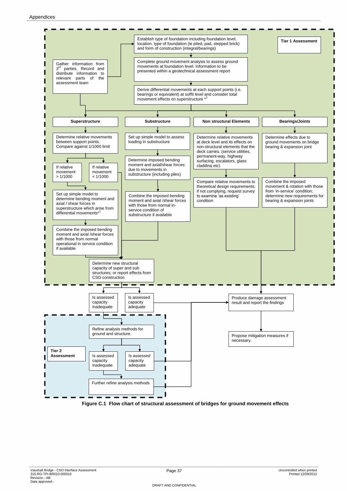
Appendices
Vauxhall Bridge - CSO Interface Assessment 315-RG-TPI-BR010-000010 Revision - AB Date approved -
Page 37 Uncontrolled when printed Printed 12/09/2012
DRAFT AND CONFIDENTIAL
Figure C.1 Flow chart of structural assessment of bridges for ground movement effects
Establish type of foundation including foundation level, location, type of foundation (ie piled, pad, stepped brick) and form of construction (integral/bearings)
Derive differential movements at each support points (i.e. bearings or equivalent) at soffit level and consider total movement effects on superstructure *
2
Determine relative movements between support points. Compare against 1/1000 limit
Determine imposed bending moment and axial/shear forces due to movements in substructure (including piles)
Combine the imposed bending moment and axial /shear forces with those from normal operational in service condition if available
Combine the imposed bending moment and axial /shear forces with those from normal in-service condition of substructure if available
Determine relative movements at deck level and its effects on non-structural elements that the deck carries. (service utilities, permanent-way, highway surfacing, escalators, glass cladding etc)
Compare relative movements to theoretical design requirements; if not complying, request survey to examine ‘as existing’ condition
Determine new structural capacity of super and sub structures; or report effects from CSO construction
Complete ground movement analysis to assess ground movements at foundation level. Information to be presented within a geotechnical assessment report
Determine effects due to ground movements on bridge bearing & expansion joint
Superstructure Bearings/Joints Substructure Non structural Elements
Set up simple model to determine bending moment and axial / shear forces in superstructure which arise from differential movements*
1
If relative movement < 1/1000
If relative movement > 1/1000
Combine the imposed movement & rotation with those from ‘in-service’ condition; determine new requirements for bearing & expansion joints
Set up simple model to assess loading in substructure
Is assessed capacity inadequate
Is assessed capacity adequate
Refine analysis methods for ground and structure.
Is assessed capacity adequate
Is assessed capacity inadequate
Further refine analysis methods
Produce damage assessment result and report the findings
Propose mitigation measures if necessary.
Tier 2
Assessment
Tier 1 Assessment
Gather information from 3
rd parties. Record and
distribute information to relevant parts of the assessment team
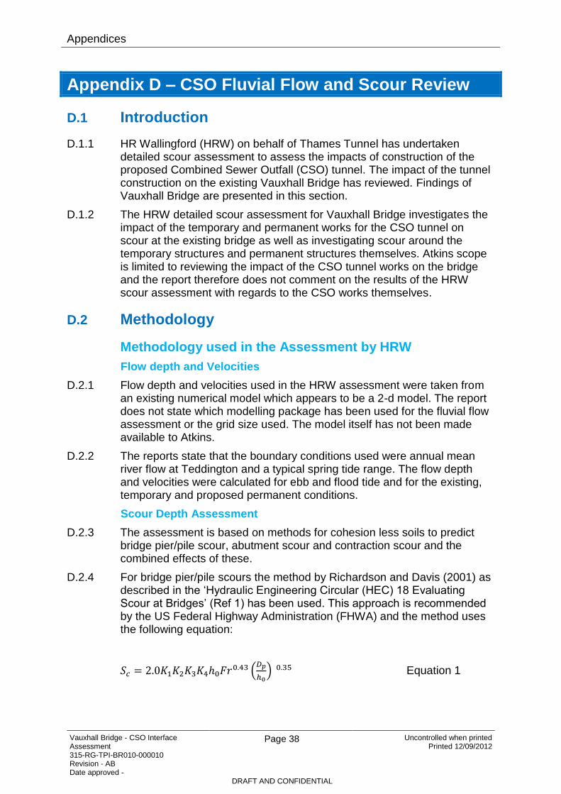
Appendices
Vauxhall Bridge - CSO Interface Assessment 315-RG-TPI-BR010-000010 Revision - AB Date approved -
Page 38 Uncontrolled when printed Printed 12/09/2012
DRAFT AND CONFIDENTIAL
Appendix D – CSO Fluvial Flow and Scour Review
D.1 Introduction
D.1.1 HR Wallingford (HRW) on behalf of Thames Tunnel has undertaken detailed scour assessment to assess the impacts of construction of the proposed Combined Sewer Outfall (CSO) tunnel. The impact of the tunnel construction on the existing Vauxhall Bridge has reviewed. Findings of Vauxhall Bridge are presented in this section.
D.1.2 The HRW detailed scour assessment for Vauxhall Bridge investigates the impact of the temporary and permanent works for the CSO tunnel on scour at the existing bridge as well as investigating scour around the temporary structures and permanent structures themselves. Atkins scope is limited to reviewing the impact of the CSO tunnel works on the bridge and the report therefore does not comment on the results of the HRW scour assessment with regards to the CSO works themselves.
D.2 Methodology
Methodology used in the Assessment by HRW
Flow depth and Velocities
D.2.1 Flow depth and velocities used in the HRW assessment were taken from an existing numerical model which appears to be a 2-d model. The report does not state which modelling package has been used for the fluvial flow assessment or the grid size used. The model itself has not been made available to Atkins.
D.2.2 The reports state that the boundary conditions used were annual mean river flow at Teddington and a typical spring tide range. The flow depth and velocities were calculated for ebb and flood tide and for the existing, temporary and proposed permanent conditions.
Scour Depth Assessment
D.2.3 The assessment is based on methods for cohesion less soils to predict bridge pier/pile scour, abutment scour and contraction scour and the combined effects of these.
D.2.4 For bridge pier/pile scours the method by Richardson and Davis (2001) as described in the ‘Hydraulic Engineering Circular (HEC) 18 Evaluating Scour at Bridges’ (Ref 1) has been used. This approach is recommended by the US Federal Highway Administration (FHWA) and the method uses the following equation:
Equation 1

Appendices
Vauxhall Bridge - CSO Interface Assessment 315-RG-TPI-BR010-000010 Revision - AB Date approved -
Page 39 Uncontrolled when printed Printed 12/09/2012
DRAFT AND CONFIDENTIAL
Where:
Dp – pile diameter (m)
h0 – flow depth (m)
K1 – correction factor for pile nose shape
K2 – correction factor for angle of attack of flow
K3 – correction factor for bed condition
K4 – correction factor for size of bed material
Fr – Froude number
Sc – equilibrium scour depth (m)
D.2.5 Abutment scour is calculated using a method developed by Hoffmans and Verheij (1997). This method is recommended by the CIRIA guide C551 – Manual on Scour at Bridges and Hydraulic Structures (Ref 2). The following equation is used:
Equation 2
Where:
Ha – horizontal width of abutment projecting into the flow (m)
Sf – safety factor
Fabut – abutment shape factor
Fv – velocity factor
Wd – depth factor
Sc – equilibrium scour depth (m)
D.2.6 Contraction scour for live-bed contraction scour is estimated using Laursen’s equation (1960) (Ref 1)
Equation 3
D.2.7 The average contraction scour depth Sc is then:
Equation 4
Where:
Q2 – flow discharge in the contracted section (m3/s)

Appendices
Vauxhall Bridge - CSO Interface Assessment 315-RG-TPI-BR010-000010 Revision - AB Date approved -
Page 40 Uncontrolled when printed Printed 12/09/2012
DRAFT AND CONFIDENTIAL
Q1 – flow discharge in the upstream channel (m3/s)
W2 – bottom width of the main channel in the contracted section (m)
W1 – bottom width of the upstream main channel
h2 – average flow depth in contracted section (m)
h1 – average flow depth in upstream main channel (m)
h0 – existing flow depth in contracted section before scour (m)
n1 – Manning’s n for the upstream channel
n2 – Manning’s n for the contracted section
k1 – exponent depending on mode of sediment transport
k2 – exponent depending on mode of sediment transport
Sc – equilibrium average scour depth (m)
D.3 Atkins Comments on Methodology
Flow Velocities and Depth
D.3.1 It is not possible to verify the model itself and whether it calculates the afflux through the bridge appropriately as the model has not been made available to Atkins and the modelling software used is unknown.
Scour Depth Assessment
D.3.2 The methodology used by HRW for the assessment of scour depths at abutment, piers and for contraction scour generally appears appropriate.
D.3.3 The equation used for the calculation of bridge pier scour is recommended by American guidance (Ref 1). The equation takes account of flow depth, Froude number of the flow and pier width as well as correction factors for pier shape, angle of the approach flow, bed condition and bed material. An additional correction factor can be applied where the pier width is large in comparison to the flow depth. The UK Design Manual for Roads and Bridges (DMRB) Volume 3, Section 4 (Ref 5) recommends an equation developed by Melville and Sutherland which takes account of pier width only with correction factors for pier shape, angle of approach flow and relative flow depth to flow width. Studies comparing different pier scour equations have shown that both methods are conservative and rarely under-predict the scour depth at the pier (Ref 1 & 3). The Melville and Sutherland equation may be slightly more conservative in some cases compared to the Richardson and Davis equation used in the assessment. Since the equation recommended in the DMRB manual does not take account of the velocity or, explicitly, of flow depth it would not appropriately predict the changes in scour depth caused by the changed flow conditions in the river channel. CIRIA C551 recommends an equation which factors the scour based on pier shape, angle of approach, velocity and relative flow depth. The equation may give some indication of the change in scour depth due to the changed conditions but since the changes are expected to be limited the equation may be less suitable for this assessment.

Appendices
Vauxhall Bridge - CSO Interface Assessment 315-RG-TPI-BR010-000010 Revision - AB Date approved -
Page 41 Uncontrolled when printed Printed 12/09/2012
DRAFT AND CONFIDENTIAL
D.3.4 None of the methodology applies specifically to tidal conditions and studies for pier scour in tidal locations are limited. It can be assumed that under tidal conditions the overall scour depth at the pier is likely to be less than predicted.
D.3.5 The methodology used for the calculation of the pier scour is considered appropriate. However, it is recommended that flood flow depth and velocities are used to compare the current results to more severe conditions during flood flows in particular for the proposed permanent works.
D.3.6 The abutment scour method used is based on the CIRIA C551 guidance which is commonly used in the UK and is considered appropriate for this assessment. As above, it is recommended that the scour depth should be reviewed based on the results of the flood flow assessment.
D.3.7 The contraction scour for the live bed conditions is based on Laursen’s equation as recommended by HEC 18. Hamil (Ref 4) observes that this equation is likely to overestimate the scour if the contraction is the result of bridge abutments and piers. Since an overestimation would give a more conservative assessment of the impacts we consider this equation to be appropriate.
D.4 Vauxhall Bridge
Brief description of the site
D.4.1 Vauxhall Bridge forms part of the A202 linking Vauxhall with Pimlico. The bridge is a 5 span steel arch bridge and was completed in 1906.
Brief description of Temporary and Permanent Works
D.4.2 The detailed scour assessment for Vauxhall Bridge is based on the temporary works design dated July 2011. However, revised drawings were provided in November 2011 and the assessment comments only qualitatively on the impact of the changes made. The temporary and permanent works extend into the river channel in two locations just upstream and downstream of Lack’s Dock. The proposed temporary works are formed by a steel sheet pile cofferdam. The upstream temporary works will block most of the southern span of the bridge. The permanent works comprise two new combined sewer outfalls and a sloping terraced area leading up to a platform at flood defence level. The Clapham CSO is located upstream of the bridge and the Brixton CSO downstream of the bridge. The sloping terrace area extends into the river channel under the bridge arch. The terraces will be planted and will be submerged during flood events. The main platform at flood defence level is located just downstream of the bridge.
D.4.3 The temporary and permanent works restrict the available flow cross section in the bridge cross section itself. This will lead to higher flow velocities in comparison to the existing conditions for the duration the temporary works are in place. The proposed permanent works permanently restrict the available flow cross section in particular during flood events although to a lesser extent than the temporary works.

Appendices
Vauxhall Bridge - CSO Interface Assessment 315-RG-TPI-BR010-000010 Revision - AB Date approved -
Page 42 Uncontrolled when printed Printed 12/09/2012
DRAFT AND CONFIDENTIAL
D.5 Data Available for the Assessment
D.5.1 The following data was available to HR Wallingford for the scour assessment at Vauxhall Bridge:
a. Scour Screening Study, HR Wallingford, Ref EX 6468, 100-RG-MDL-WALLI-0016-AD.
b. OS maps of the river reach.
c. Drawings:
i Foreshore worksite layout (Ref: 100-DA-CNS-PLH1X-259010, Rev AB and Rev AC).
d. Thames Tunnel Overwater Grab Sampling, particle size distribution for holes VB01-17.
e. Bathymetric survey, Mar 2009.
f. Detailed fluvial modelling, HR Wallingford report EX6171 Albert Embankment Fluvial Modelling.
g. Borehole in river channel, BH SR2059, Fugro, April 2010.and BH SR5004-5007b, Soil Engineering, April/May 2011.
D.6 Existing Scour Depth around Bridge Piers and Abutments
D.6.1 The assessment undertaken by HR Wallingford includes bathymetric data surveyed in March 2009. The data itself has not been made available to Atkins but information provided in the assessment indicates that the bed levels on the downstream side of the bridge are lower than upstream and in the bridge cross section itself. The deepest bed levels occur downstream of piers 2, 3 and 4 (numbered 1 to 4 from South to North). The proposed temporary and permanent works are located in an area with shallow bed levels which will be exposed at low water levels. The minimum bed level observed on the upstream side of the bridge piers 2 and 3 (mid channel piers) is -6mAOD with a similar bed level also found midway between the two piers. The maximum scour depth in relation to the average bed level was determined by HRW as 2m. Scour depth both on the upstream and downstream side of piers 2 and 3 are up to 2m below the existing average bed level.
D.7 Predicted Scour Depths
D.7.1 The predicted scour depth for the existing condition at the bridge piers based on Equation 1 above was calculated as 2.2m for the ebb tide maximum velocity and flow depth at piers 2 and 3 and 2.34m on the flood tide maximum velocities. These values correspond well with observed maximum scour values at the site. The scour depth assumes granular materials as observed in the grab samples as the bed material. As the scour progresses this material may be removed and underlying material may be exposed. The borehole shows the underlying material to be clay.
Appendices
Vauxhall Bridge - CSO Interface Assessment 315-RG-TPI-BR010-000010 Revision - AB Date approved -
Page 43 Uncontrolled when printed Printed 12/09/2012
DRAFT AND CONFIDENTIAL
Cohesive materials are likely to limit scour development and the assessment therefore represents a conservative estimate.
D.7.2 The predicted scour depth for the temporary works was based on outputs of flow modelling which cannot be verified as the model itself has not been provided to Atkins. The assessment states that the depth averaged flow velocity at piers 2 and 3 is increased 0.11 m/s during the flood tide and 0.07 m/s for the ebb tide as a result of the temporary works. The flow depth during flood and ebb tide is decreased by 0.01m. The changes in the flow conditions are limited and occur only during the construction period. As previously stated, the limited impact may be expected due to the use of the mean annual flow and it may be expected that the impact of the works would be higher for flood flows. The total impact on the predicted scour depth, if the temporary conditions would prevail for a sufficiently long period of time, is an increase in scour depth by 0.09m. The maximum predicted pier scour depth is 2.43m.
D.7.3 For the permanent case the impact of the works on the flow velocity at the piers is an increase of up to 0.03 m/s during flood tide and ebb tide. A decrease in water levels of up to 0.01m is predicted. The impact of the permanent works on the total maximum scour depth is 0. The maximum pier scour depth predicted is 2.36m representing an increase in scour depth of 0.02m.
D.7.4 The above scour depths apply to the conditions prevailing at piers 2 and 3. The impact on pier 1 can be expected to be more significant due to the proximity of the pier to the works and the more complex flow patterns which can be expected at this pier. The assessment recommends monitoring of the scour at pier 1 both during and after completion of the works.
D.7.5 With regards to the changes made to the proposals since July 2011 the assessment concludes that the impact of the changes will be limited and the scour predicted within the cross section at Vauxhall Bridge will not be significantly different to that which had been modelled. It appears from the drawings provided as part of the report that the extent of the temporary and permanent works into the river channel has not significantly changed. The changes do not appear likely to cause a significant change in flow patterns and Atkins’ therefore agrees with HRW’s assessment of this issue.
D.7.6 The predicted additional scour depth due to contraction scour as a result of the temporary works is reported to be a maximum of 0.8m. For the proposed permanent works the predicted increase in scour depth is 0.4m. Given the frequency at which the mean annual discharge can be expected to occur it is likely that significant overall erosion of the channel may occur in the temporary case. The total combined increase in scour adjacent to the piers 2 to 4 is predicted to be up to 0.89m and the predicted maximum combined scour increase for the permanent case is 0.42m. However, due to the overall depth of the structure foundation this is unlikely to threaten the integrity of the bridge structure

Appendices
Vauxhall Bridge - CSO Interface Assessment 315-RG-TPI-BR010-000010 Revision - AB Date approved -
Page 44 Uncontrolled when printed Printed 12/09/2012
DRAFT AND CONFIDENTIAL
D.8 Conclusion and Recommendations
Conclusions
D.8.1 Based on the assessment undertaken by HR Wallingford we draw the following conclusions:
D.8.2 Basis of Assessment
D.8.3 The assessment is based on a relatively low flow (mean annual flow) in the Thames. The impact of flood flows on flow velocities and scour depths have not been considered. Scour depths during periods of high flow may therefore be greater than those predicted.
D.8.4 The effect of the temporary and permanent works on the pier scour at Vauxhall Bridge piers 2 to 4 is predicted by HRW to be negligible.
D.8.5 The effect of the temporary works on the contraction scour at Vauxhall Bridge is predicted by HRW to be limited as the maximum scour depth would only develop over a significant period of time.
D.8.6 The effect of the permanent works on the contraction scour at Vauxhall Bridge is predicted by HRW is estimated as up to 0.8m. Given the frequency at which flows higher than the mean annual flow occurs during the temporary works contraction scour up to this value may occur. The reduction in bed level is unlikely to affect the stability of the bridge. The contraction scour for the permanent works is predicted to be up to 0.4m.
D.8.7 The maximum cumulative increase in scour depth at the pier is predicted by HRW to be up to 0.89m due to the impact of the temporary works and up to 0.42m for the permanent works impact. This reduction in the bed levels is unlikely to affect the stability of the bridge given the overall depth of the foundations.
D.8.8 The impact of the proposed works on pier 1 at Vauxhall Bridge is difficult to predict without undertaking more detailed modelling. The HR Wallingford assessment recommends regular monitoring during and following completion of the works. Within the limitations of the river flows considered, we concur with this recommendation, with the addition that the level of scour should also be checked any period of increased river flow. If significant scour is observed additional protection to prevent extensive scour may be required.
D.9 Recommendations
D.9.1 Based on the available reports prepared by HR Wallingford we recommend the following:
D.9.2 Clarification should be requested on the reason for using annual mean river flows for the assessment of permanent works rather than a 1 in 100 year flood event or higher in accordance with UK and US guidance.
D.9.3 If suitable justification cannot be provided, the effects of a significant flood event on scour for the temporary and permanent case should be considered. If Atkins were to undertake this assessment we would require

Appendices
Vauxhall Bridge - CSO Interface Assessment 315-RG-TPI-BR010-000010 Revision - AB Date approved -
Page 45 Uncontrolled when printed Printed 12/09/2012
DRAFT AND CONFIDENTIAL
the flood modelling undertaken on behalf of the Environment Agency for this reach of the River Thames. We would suggest that a 1 in 10 year event may be considered suitable for the temporary works and the 1 in 200 year event is used for the permanent works.
D.9.4 Scour should be monitored and it is recommended that an inspection in accordance with the recommendations of DMRB Vol 3, Section 4 is undertaken following significant flood events equivalent to a 1 in 100 year return period following completion of construction.
D.9.5 During construction inspections of pier scour should be undertaken if a significant flood event greater than a 1 in 10 year return period occurs during the construction period.
D.9.6 Scour at pier 1 of Vauxhall Bridge should be monitored annually during construction and for a period of 5 years after completion of construction.
D.10 References
Hydraulic Engineering Circular (HEC) 18 Evaluating Scour at Bridges, 4th Edition, May 2001, US Department of Transport, Federal Highways Administration.
CIRIA 551 - Manual on Scour at Bridges and Hydraulic Structures, May, Ackers, Kirby, 2002.
Validation of some bridge pier scour formulae using field and laboratory data, Mohamed, Thamer Ahmed; Noor, Megat Johari M.M.; Ghazali, Abdul Halim; Huat, Bujang B.K, American Journal of Environmental Sciences, April 2005.
Bridge Hydraulics, Les Hamil, 1999.
Design Manual for Roads and Bridges, Volume 3, Section 4.

Copyright notice Copyright © Thames Water Utilities Limited September 2013. All rights reserved. Any plans, drawings, designs and materials (materials) submitted by Thames Water Utilities Limited (Thames Water) as part of this application for Development Consent to the Planning Inspectorate are protected by copyright. You may only use this material (including making copies of it) in order to (a) inspect those plans, drawings, designs and materials at a more convenient time or place; or (b) to facilitate the exercise of a right to participate in the pre-examination or examination stages of the application which is available under the Planning Act 2008 and related regulations. Use for any other purpose is prohibited and further copies must not be made without the prior written consent of Thames Water. Thames Water Utilities LimitedClearwater Court, Vastern Road, Reading RG1 8DB The Thames Water logo and Thames Tideway Tunnel logo are © Thames Water Utilities Limited. All rights reserved.
Copyright notice Copyright © Thames Water Utilities Limited September 2013. All rights reserved. Any plans, drawings, designs and materials (materials) submitted by Thames Water Utilities Limited (Thames Water) as part of this application for Development Consent to the Planning Inspectorate are protected by copyright. You may only use this material (including making copies of it) in order to (a) inspect those plans, drawings, designs and materials at a more convenient time or place; or (b) to facilitate the exercise of a right to participate in the pre-examination or examination stages of the application which is available under the Planning Act 2008 and related regulations. Use for any other purpose is prohibited and further copies must not be made without the prior written consent of Thames Water. Thames Water Utilities LimitedClearwater Court, Vastern Road, Reading RG1 8DB The Thames Water logo and Thames Tideway Tunnel logo are © Thames Water Utilities Limited. All rights reserved.
10243-A4P-Copyright-imp-V01.pdf p1 12:03:39 September 21, 2013