application-specific integrated lenses for displays · 45.1 / m. popovich 1060 • sid 00 digest...
TRANSCRIPT

45.1 / M. Popovich
• SID 00 DIGEST 1060
45.1: Application Specific Integrated Lenses for Displays Milan Popovich
DigiLens, Ltd., 39 Broad Street, Syston, Leicester, LE71GH, United Kingdom
Stephen Sagan DigiLens, Inc. 306 Potrero Ave. Sunnyvale, CA 94086-4113
Abstract Application Specific Integrated Lenses (ASILs), based on a unique holographic polymer dispersed liquid crystal (H-PDLC) material system offering high efficiency, fast switching and low switching voltage are being developed for display and telecommunication applications. The basic properties and key benefits of ASILs in displays are reviewed.
1. Introduction Optical switching has a key role in the emerging technologies of microdisplays and optical networks for telecommunications. Typical applications range from colour sequential filtering of a white light source to deflecting a beam into one or more different directions. Traditionally, optical switching has involved electro -mechanical techniques. Solid state solutions based on liquid crystal and electro-optical devices have failed to deliver optical efficiency, switching speed and low power consumption in a single device. Now, a new photonic technology based on holographic polymer dispersed liquid crystal H-PDLC materials [1] offers a new approach based on Electrically Switchable Holographic Optical Elements (ESHOEs). DigiLens is the name shared by this new technology and the Silicon Valley start-up company set up to exploit it. Using ESHOEs as a fundamental building block, DigiLens is developing a new solid state optical device technology, the Application Specific Integration Lens (ASIL) for displays and telecommunications. ASILs provide the display designer with a switching technology and additional benefits stemming from the unique ability of holographic optical elements to compress conventional optical systems into compact and lightweight form factors [2]. ASILs are expected to have a major impact on the complexity and cost of a broad gamut of microdisplay applications, including projection and near-eye.
2. Material System and Basic Physics ESHOEs differ from conventional HOEs in one key respect, their
refractive index modulation can be varied. In ESHOEs the Bragg surfaces are densely populated by microdroplets of liquid crystal, interspersed with regions of relatively pure photopolymer. The process of recording a ESHOE begins with a homogeneous mix of monomer, photo-active initiators and liquid crystal sandwiched between two transparent ITO coated substrates which is exposed to intersecting laser beams giving rise to an interference pattern. Photo-polymerization is initiated in the high light intensity areas and monomers begin linking with one another to form polymer chains. Monomers diffuse into these bright regions to link up with the rapidly forming polymer chains. Simultaneously, the LC, which will only mix with monomer, diffuses to the lower intensity areas, which saturate, precipitating droplets that grow in size as the diffusion process continues. When the diffusion process has reached an appropriate stage, the PDLC is then flooded with uniform laser light to completely surround the LC droplets with polymer, resulting in a solid hologram layer. No further post processing is required. Since the diameters of the LC droplets are considerably less than the wavelength of light, the clouds of droplets are ‘seen’ as a homogenous region with an average index, slightly lower than the interspersed polymer regions. This gives rise to a modulation of the refractive index, which is a very critical driver of the hologram performance. The control of the dynamic balance of the rates of diffusion and the rates of polymerization is the key to higher modulations, and hence high quality holograms. The resulting ESHOE exhibits very high diffraction efficiencies. Referring to the transmission ASIL shown in Figure 1, when an electric field is applied via the ITO electrodes, the natural orientation of the LC molecules is changed causing the refractive index modulation of the fringes and hence the diffraction efficiency to reduce with increasing voltage - effectively erasing the hologram. In transmission ASILs the LC droplets tend to be elongated with their major axes aligned normal to the Bragg surfaces. The operation of reflection ASILs, where the Bragg surfaces tend to be almost parallel to the substrate, is similar in concept except that the droplets tend to have a much lower anisotropy, requiring higher switching voltages
Figure 1. Basic Physics of ASILs
ISSN0000-0966X/00/3101-1060-$1.00+.00 © 2000 SID
45.1 / M. Popovich
SID 00 DIGEST • 1061
3. Implementing ASIL Technology An ASIL is essentially a stack of ESHOEs. Each ESHOE is sandwiched between flat optical glass or plastic substrates with ITO electrode coatings applied to the inside surfaces of each plate. The thickness of the ESHOE layer is a design parameter and will typically range from around 5 to 30 microns depending on the type of ASIL - reflective or transmissive - and the spectral and angular bandwidths that are required for a particular application. It is desirable that the ESHOE is as thin as possible to minimize switching voltages. The extent to which thickness can be reduced is determined by efficiency requirements and fundamental holographic optical limits, which dictate that below around 5 microns an ESHOE will no longer behave as a Bragg hologram. Substrates are the most important factor influencing the thickness of an ASIL. Glass substrates typically range from 0.4-1.0 mm; plastic substrates can be up to five times thinner. A three color ASIL formed with glass of thickness 0.4 mm will have an overall thickness of 2.4 mm. The effective apertures of ASILs can range from as small as 5 mm diagonal to aperture sizes used in most practical optical systems. Although the planar laminar architectures used in ASILs considerably ease the problems of manufacture and alignment, the basic technology will in future be extended to curved geometries which will offer further benefits in terms of optical performance and overall form factor improvement.
DigiLens provides a complete ASIL authoring service. Typically, this starts with a system design leading to an optical prescription computed using standard optical design software (e.g. Code V). ASILs designed for imaging will require phase profile/distortion compensation and, in general, different prescriptions for each ASIL layer. A related task is the design of construction optics, where for more complex parts it will be necessary to specify Computer Generated Holograms (CGHs). Fabrication of ASILs calls for state of the art laser exposure and optical alignment procedures and generally requires careful control of recording conditions including laser power, stray reflections, exposure time, ambient air quality, temperature and other parameters. DigiLens’s fabrication plant at Sunnyvale CA is currently equipped with three separate recording tables (for red green and blue ASILs) together with Class 100 clean room facilities for material processing. DigiLens is developing proprietary techniques for creating masters, replication and assembly of ASILs with the ultimate goal of setting up a replication plant capable of 10,000 devices per month.
4. Electro Optical Characteristics of ASILs The holographic polymer-dispersed liquid crystal material system used in ASILs is unique in offering potential for high efficiency, fast switching and low switching voltage. The material can be optimized to operate from the near ultraviolet, at around 400 nm, out to the near infrared, at around 1600 nm. The key parameter is the refractive index modulation, which for display applications typically ranges from 0.03 to 0.05.
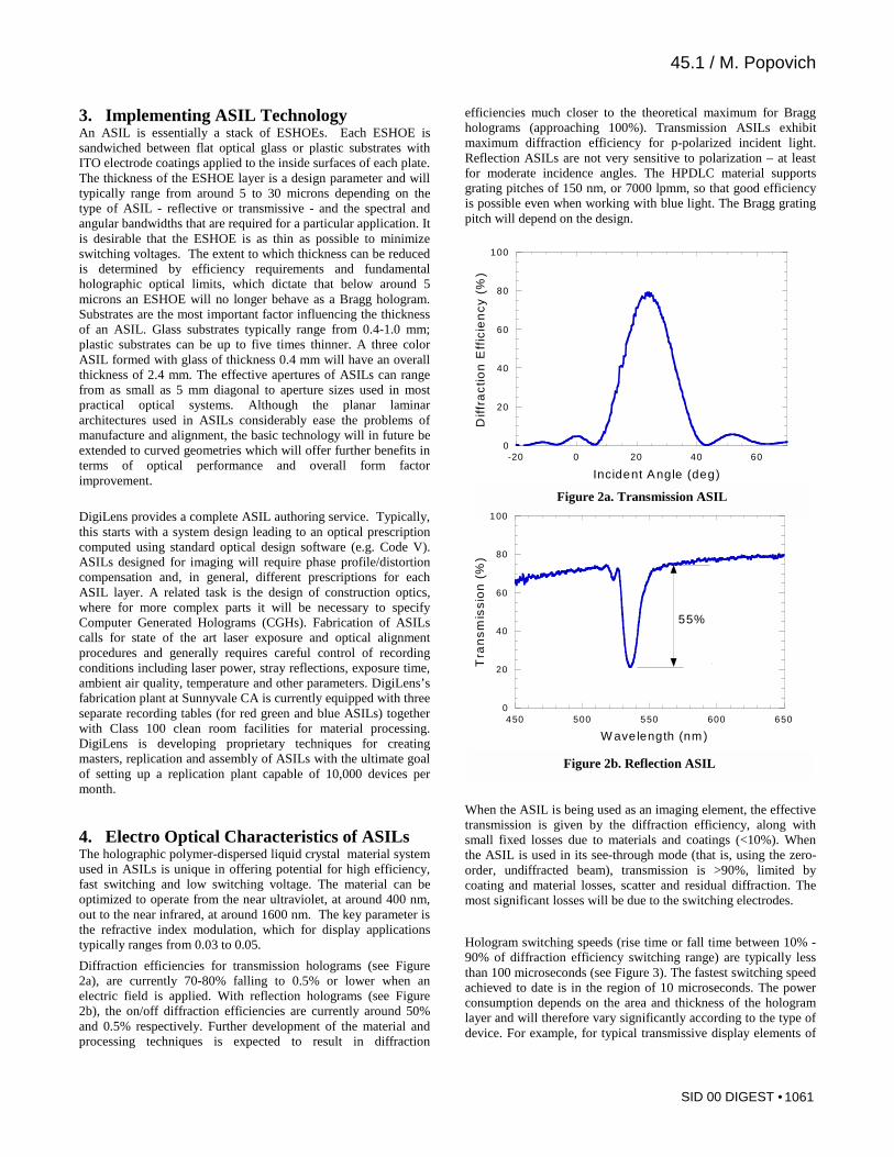
Diffraction efficiencies for transmission holograms (see Figure 2a), are currently 70-80% falling to 0.5% or lower when an electric field is applied. With reflection holograms (see Figure 2b), the on/off diffraction efficiencies are currently around 50% and 0.5% respectively. Further development of the material and processing techniques is expected to result in diffraction
efficiencies much closer to the theoretical maximum for Bragg holograms (approaching 100%). Transmission ASILs exhibit maximum diffraction efficiency for p-polarized incident light. Reflection ASILs are not very sensitive to polarization – at least for moderate incidence angles. The HPDLC material supports grating pitches of 150 nm, or 7000 lpmm, so that good efficiency is possible even when working with blue light. The Bragg grating pitch will depend on the design.
When the ASIL is being used as an imaging element, the effective transmission is given by the diffraction efficiency, along with small fixed losses due to materials and coatings (<10%). When the ASIL is used in its see-through mode (that is, using the zero-order, undiffracted beam), transmission is >90%, limited by coating and material losses, scatter and residual diffraction. The most significant losses will be due to the switching electrodes.
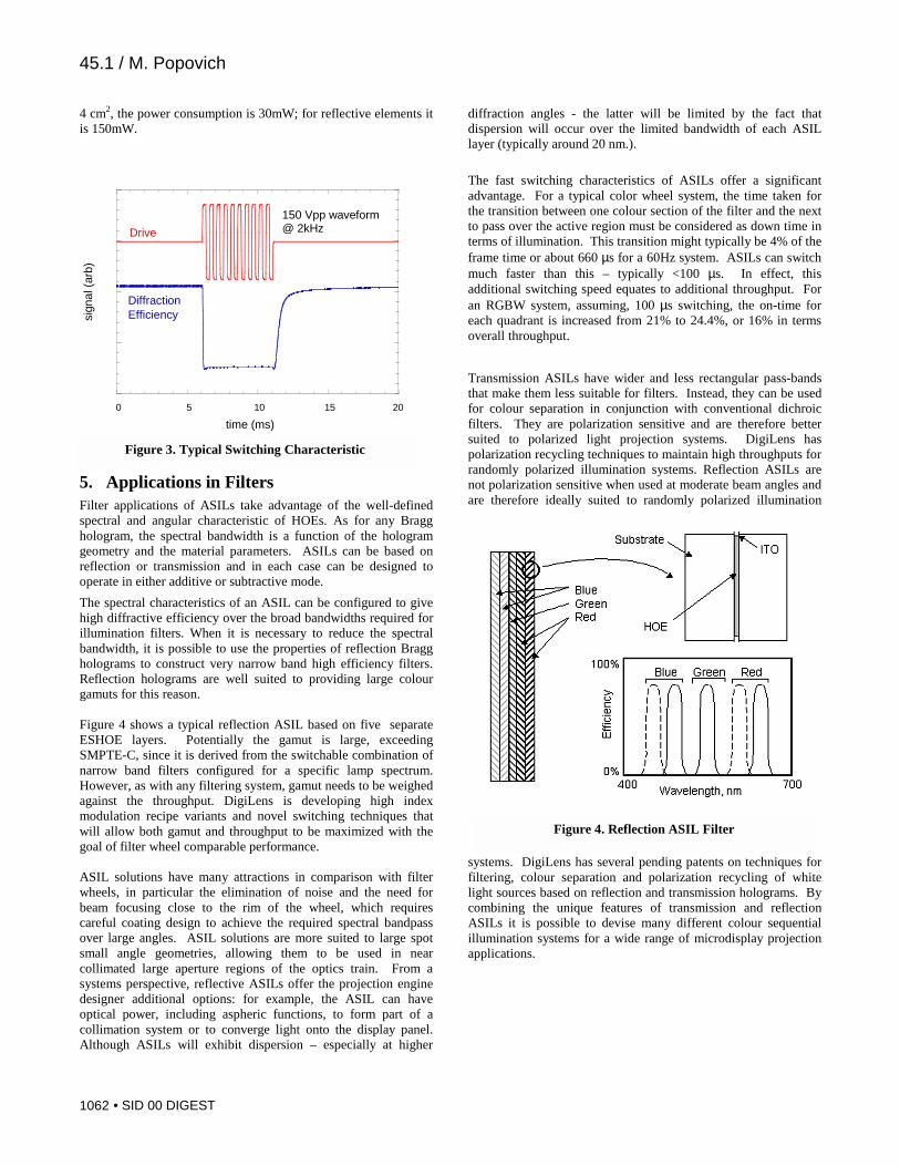
Hologram switching speeds (rise time or fall time between 10% - 90% of diffraction efficiency switching range) are typically less than 100 microseconds (see Figure 3). The fastest switching speed achieved to date is in the region of 10 microseconds. The power consumption depends on the area and thickness of the hologram layer and will therefore vary significantly according to the type of device. For example, for typical transmissive display elements of
0
20
40
60
80
100
-20 0 20 40 60
Dif
fra
cti
on
Eff
icie
nc
y (%
)Incident Angle (deg)
Figure 2a. Transmission ASIL
0
20
40
60
80
100
450 500 550 600 650
Tra
ns
mis
sio
n (
%)
W avelength (nm)
55%
Figure 2b. Reflection ASIL
45.1 / M. Popovich
• SID 00 DIGEST 1062
4 cm2, the power consumption is 30mW; for reflective elements it is 150mW.
5. Applications in Filters Filter applications of ASILs take advantage of the well-defined spectral and angular characteristic of HOEs. As for any Bragg hologram, the spectral bandwidth is a function of the hologram geometry and the material parameters. ASILs can be based on reflection or transmission and in each case can be designed to operate in either additive or subtractive mode.
The spectral characteristics of an ASIL can be configured to give high diffractive efficiency over the broad bandwidths required for illumination filters. When it is necessary to reduce the spectral bandwidth, it is possible to use the properties of reflection Bragg holograms to construct very narrow band high efficiency filters. Reflection holograms are well suited to providing large colour gamuts for this reason. Figure 4 shows a typical reflection ASIL based on five separate ESHOE layers. Potentially the gamut is large, exceeding SMPTE-C, since it is derived from the switchable combination of narrow band filters configured for a specific lamp spectrum. However, as with any filtering system, gamut needs to be weighed against the throughput. DigiLens is developing high index modulation recipe variants and novel switching techniques that will allow both gamut and throughput to be maximized with the goal of filter wheel comparable performance. ASIL solutions have many attractions in comparison with filter wheels, in particular the elimination of noise and the need for beam focusing close to the rim of the wheel, which requires careful coating design to achieve the required spectral bandpass over large angles. ASIL solutions are more suited to large spot small angle geometries, allowing them to be used in near collimated large aperture regions of the optics train. From a systems perspective, reflective ASILs offer the projection engine designer additional options: for example, the ASIL can have optical power, including aspheric functions, to form part of a collimation system or to converge light onto the display panel. Although ASILs will exhibit dispersion – especially at higher
diffraction angles - the latter will be limited by the fact that dispersion will occur over the limited bandwidth of each ASIL layer (typically around 20 nm.).
The fast switching characteristics of ASILs offer a significant advantage. For a typical color wheel system, the time taken for the transition between one colour section of the filter and the next to pass over the active region must be considered as down time in terms of illumination. This transition might typically be 4% of the frame time or about 660 µs for a 60Hz system. ASILs can switch much faster than this – typically <100 µs. In effect, this additional switching speed equates to additional throughput. For an RGBW system, assuming, 100 µs switching, the on-time for each quadrant is increased from 21% to 24.4%, or 16% in terms overall throughput.
Transmission ASILs have wider and less rectangular pass-bands that make them less suitable for filters. Instead, they can be used for colour separation in conjunction with conventional dichroic filters. They are polarization sensitive and are therefore better suited to polarized light projection systems. DigiLens has polarization recycling techniques to maintain high throughputs for randomly polarized illumination systems. Reflection ASILs are not polarization sensitive when used at moderate beam angles and are therefore ideally suited to randomly polarized illumination
systems. DigiLens has several pending patents on techniques for filtering, colour separation and polarization recycling of white light sources based on reflection and transmission holograms. By combining the unique features of transmission and reflection ASILs it is possible to devise many different colour sequential illumination systems for a wide range of microdisplay projection applications.
-100
-50
0
50
100
0 5 10 15 20
sign
al (
arb)
time (ms)
150 Vpp waveform @ 2kHz Drive
Diffraction Efficiency
Figure 3. Typical Switching Characteristic
Figure 4. Reflection ASIL Filter

45.1 / M. Popovich
SID 00 DIGEST • 1063
6. Applications in Imaging DigiLens is currently developing ASILs for a range of microdisplay applications, including projectors, wearable displays, compact displays for telephones and others. The requirement for unique and demanding form factors is particularly acute in the case of near-eye displays which, by definition, need to be compact and lightweight and should ideally allow a high degree of see-through. The extreme miniaturization of microdisplays, although providing a route to low cost components, poses the fundamental problem of magnifying a tiny input image to provide a viewable image over a wide field of view. Small input images do not easily equate to user needs for large fields of view and exit pupils and compact form factors. This presents a major challenge for conventional optics where the demanding requirements of large exit pupil, wide field of view, extreme off axis imaging, see-through and high brightness tend to push optical designs towards more cumbersome configurations.
The ability of Holographic Optical Elements (HOEs) to compress complex optical systems into more compact functional elements is well known. However, all HOEs have one major problem that has tended to limit their application in practical imaging systems: they are inherently narrow band devices. ASILs eliminate the colour crosstalk problem by using separate red, green and blue ESHOEs stacked together to form a single element. The holographic bandwidths can be exactly matched to those of the primary colors needed to sequentially illuminate the microdisplay. Since ASILs essentially create separate red, green and blue channels, individual ESHOEs only need to be corrected over a relatively narrow bandwidth. With the colour correction problem eased, the optical designer is free to attempt more extreme optical form factors.
DigiLens’s DL40 wearable display – the world’s first compact colour holographic display (see Figures 5), with a field of view of 30 degrees x 40 degrees - uses a transmission ASIL, a passive reflection HOE recorded in a DuPont material and a system of
refractive cylinder/aspheric elements. The design goal was to achieve a compact form-factor with minimal weight and obstruction in front of the eyes and with the weight distributed
towards the side of the head. Since a highly off-axis design was required to achieve the form factor, a major optical design challenge was to minimise the dispersion and chromatic aberrations contributed by the holograms. A design which employs a curved eyepiece is shown in Figure 6. In future variants of the design, the combination of lasers with ASILs is expected to minimise the problem of color correction.
7. Summary ASILs are likely to have a major impact on the cost and form factor of near eye and projection display systems. As a fundamental switching technology ASILs benefit from having no moving parts; they are completely solid state and silent in operation. ASILs enable full colour applications of Bragg HOEs and are complementary to color sequentially illuminated microdisplay technology. ASILs have all of the functionality of conventional HOEs, ie allowing extreme deflections of light paths and offering compact or ergonomic form factors unachievable using conventional optics.
8. Acknowledgments Our thanks to our colleagues John Storey and David Jones for their contributions in the development of the technical information.
9. References [1] RL Sutherland, Natarajan, LV and Tondiglia, VP, Bragg
gratings in an acrylate polymer consisting of periodic polymer-dispersed liquid crystals, SPIE 1080, 83 (1993)
[2] MM Popovich, Small Displays Loom Large, Photonics Spectra, March, 159 (2000)
Figure 6. Wearable Display Optical Design
Figure 5. Wearable Display Design