applications of a non-interferometric x-ray phase - iopscience
TRANSCRIPT

Journal of Instrumentation
Applications of a non-interferometric x-ray phasecontrast imaging method with both synchrotronand conventional sourcesTo cite this article M Endrizzi et al 2013 JINST 8 C05008
View the article online for updates and enhancements
You may also likeVisualization of small lesions in ratcartilage by means of laboratory-based x-ray phase contrast imagingMassimo Marenzana Charlotte K HagenPatricia Das Neves Borges et al
-
Technical note development andvalidation of a Monte Carlo tool foranalysis of patient-generated photonscatterKaiming Guo Harry Ingleby Idris Elbakriet al
-
High resolution divergent-beam X-raytopographyB K Tanner and C J Humphreys
-
Recent citationsImproved iterative tomographicreconstruction for x-ray imaging with edge-illuminationPeter Modregger et al
-
Large-area full field x-ray differentialphase-contrast imaging using 2D tiledgratingsTobias J Schroumlter et al
-
Increasing the field of view in gratingbased X-ray phase contrast imaging usingstitched gratingsJ Meiser et al
-
This content was downloaded from IP address 1772151102 on 13122021 at 0632
2013 JINST 8 C05008
PUBLISHED BY IOP PUBLISHING FOR SISSA MEDIALAB
RECEIVED December 23 2012ACCEPTED May 7 2013
PUBLISHED May 30 2013
7th MEDICAL APPLICATIONS OF SYNCHROTRON RADIATION WORKSHOP (MASR 2012)SHANGHAI SYNCHROTRON RADIATION FACILITY (SSRF)17ndash20 OCTOBER 2012
Applications of a non-interferometric x-ray phasecontrast imaging method with both synchrotron andconventional sources
M Endrizzi PC Diemoz PRT Munro CK Hagen MB Szafraniec TP MillardCE Zapata RD Speller and A Olivo1
Department of Medical Physics and Bioengineering University College LondonMalet Place Gower Street London WC1E 6BT UK
E-mail aolivouclacuk
ABSTRACT We have developed a totally incoherent non-interferometric x-ray phase contrastimaging (XPCI) method This is based on the edge illumination (EI) concept developed at theELETTRA synchrotron in Italy in the late lsquo90s The method was subsequently adapted to the di-vergent beam generated by a conventional source by replicating it for every detector line throughsuitable masks The method was modelled both with the simplified ray-tracing and with the morerigorous wave-optics approach and in both cases excellent agreement with the experimental re-sults was found The wave-optics model enabled assessing the methodsrsquo coherence requirementsshowing that they are at least an order of magnitude more relaxed than in other methods with-out this having negative consequences on the phase sensitivity Our masks have large pitches (upto 50 times larger than in grating interferometry for example) which allows for manufacturingthrough standard lithography scalability cost-effectiveness and easiness to align When applied toa polychromatic and divergent beam generated by a conventional source the method enables thedetection of strong phase effects also with uncollimated unapertured sources with focal spots of upto 100 microm compatible with the state-of-the-art in mammography When used at synchrotrons itenables a contrast increase of orders of magnitude over other methods Robust phase retrieval wasproven for both coherent and incoherent sources and additional advantages are compatibility withhigh x-ray energies and easy implementation of phase sensitivity in two directions simultaneouslyThis paper briefly summarizes these achievements and reviews some of the key results
KEYWORDS Inspection with x-rays Detection of defects X-ray radiography and digital radiog-raphy (DR) X-ray mammography and scinto- and MRI-mammography
1Corresponding author
ccopy 2013 IOP Publishing Ltd and Sissa Medialab srl doi1010881748-0221805C05008
2013 JINST 8 C05008
Contents
1 Introduction 1
2 Materials and methods 2
3 Results 4
4 Conclusions 6
1 Introduction
X-ray phase contrast imaging (XPCI) exploits interference and refraction effects (ldquophaserdquo effectshence the name) instead of attenuation to generate image contrast By doing this it both enhancesthe visibility of all detail in an x-ray image and it enables the visualization of features classicallyconsidered x-ray invisible due to lack of attenuation contrast The rationale behind this is thatconsidering the real and imaginary parts of the refractive index n [1]
n = 1minusδ + iβ (11)
it can be noted that the unit decrement of the real part δ (responsible for phase effects) is muchlarger than the imaginary part β (responsible for attenuation) typically up to 1000 times larger formost materials and over a wide range of x-ray energies
Initially this was exploited either through free space propagation [2 3] or perfect crystals(ldquoanalyser basedrdquo imaging [4ndash6]) This works very well with synchrotron x-ray beams whichtypically possess both spatial and temporal coherence Outside synchrotrons effective implemen-tations of XPCI become more difficult Free-space propagation methods tolerate relaxed temporalcoherence conditions [3] but suffer strongly from reductions in spatial coherence as the source di-mensions are made larger phase effects rapidly vanish [7ndash11] This means that microfocal sourcescan be used as an alternative to synchrotrons but at the price of long exposure times (hours [3])due to their low emitted flux Crystal methods on the other hand can tolerate a relaxed degree ofspatial coherence [12] but intrinsically impose high temporal coherence as the crystal automati-cally selects a narrow bandwidth out of the spectrum emitted by the source
In the late nineties we were trying to solve this conundrum at the SYRMEP (SynchrotronRadiation for MEdical Physics) beamline of the ELETTRA synchrotron in Trieste Italy by com-bining the aspects of free-space propagation that make it resilient to reduced temporal coherencewith those that enable crystal methods to tolerate somewhat relaxed spatial coherence The latteraspect is due to the fact that crystals can be seen as very effective angular filters and can thus beused to exploit refraction effects with high accuracy However having to employ a crystal practi-cally forces the use of monochromatic radiation The goal was therefore to develop an approachthat could perform a fine angular selection on refracted x-rays without employing a crystal This
ndash 1 ndash
2013 JINST 8 C05008
Figure 1 The basic implementation of the edge illumination method with synchrotron radiation
was achieved by means of the edge illumination (EI) method which consists in illuminating onlythe edges of the detector pixels [13] In this way small deviations in the x-ray direction are suffi-cient to deflect x-rays out of the detector active surface causing dark fringes and vice-versa (seefigure 1) Images with a strong similarity to those provided by analyser based imaging are obtainedin this way [13] but the absence of the crystal makes the method amenable to divergent and poly-chromatic beams This is achieved by means of two aperture masks [14 15] placed one beforeand one after the imaged sample (sometimes referred to as ldquocoded aperturesrdquo although they differsignificantly from those used in nuclear medicine or astronomy) which enable repeating the EIconfiguration for every row (or column) of pixel in an area detector (see figure 2 below)
It should be noted that despite some superficial similarity in the setup with grating (or ldquoshear-ingrdquo or ldquoTalbotrdquo) interferometry [16ndash18] the method is based on a different physical principle (EIinstead of Talbot self-imaging) and is in fact a totally incoherent method while grating interfer-ometry still requires at least spatial coherence which (in the TalbotLau configuration [19]) canalso be achieved through the introduction of the ldquosourcerdquo grating [20]
While in grating interferometry the gratings have pitches of the order of a few micron thusrequiring highly specialized fabrication facilities and very fine alignments (of down to a few tensof nm [21]) our masks have pitches up to 50 times larger which allows for manufacturing throughstandard lithography scalability cost-effectiveness and easiness to align The larger pitch togetherwith the fact that stepping one mask with respect to the other is not required relaxes the alignmentrequirements to a couple of microm [22] Moreover the pre-sample mask (see figure 2) protects thesample from unwanted radiation enabling the achievement of clinically acceptable doses [23]
Most importantly this set-up provides strong phase contrast signals with focal spots of up to100 microm [15] compatible with current state-of-the-art mammography sources without requiringexcessive source-to-sample distances Together with the fact that the full unfiltered polychromaticbeam produced by a Mo [14 15 23] or a W [22 24] source can be used this means that oursis the first XPCI method working with sources that are simultaneously incoherent both spatiallyand temporally Despite this phase sensitivity at least equivalent to that of grating interferometersoperated on the 3rd Talbot order was recently demonstrated [23]
2 Materials and methods
In its basic synchrotron implementation the EI method is extremely simple (see figure 1)All it requires is beam pre-shaping through a slit (the vertical aperture of which determines the
phase sensitivity together with the sample to detector distance [13 15]) and a ldquosensitivity edgerdquoon the detector surface If a ldquolinearrdquo detector consisting of a single row of pixels is availablethe edge of the pixel row itself can be used (like in figure 1) With a more conventional detector a
ndash 2 ndash
2013 JINST 8 C05008
Figure 2 Extension of the edge illumination method to larger beam cross-sections (a) and (b) show the par-allel (typically synchrotron) and divergent (typically conventional source) beam configurations respectively
polished absorbing edge (eg made of tungsten carbide) can be mounted in front of the detector andaligned with a row of pixels to create a sharp transition between sensitive and insensitive detectorareas [25] The beam collimated by the ldquoshapingrdquo slit is then positioned such that it straddles theedge between sensitive and insensitive regions on the detector In this synchrotron setup where thebeam is often very thin in the vertical direction samples are typically scanned through the beam toobtain the two-dimensional images In our case the sample is scanned immediately downstreamof the ldquoshapingrdquo slit During this scan when one of the details in the sample touches the upperpart of the beam it can refract x-rays downwards (with respect to figure 1) These x-rays whichwould normally miss the pixel are thus counted The number of counts corresponding to thatsample position would therefore be increased creating a bright fringe along that side of the detailLikewise when the detail grazes the bottom part of the beam x-rays that are normally counted canbe deviated upwards and thus possibly miss the detector creating a negative fringe ldquoDifferentialrdquo(ie proportional to the first derivative of the phase shift) XPCI images are obtained in this way justlike the ones obtained on one side of the reflectivity curve of an analyser crystal [26] Although inour case the differential nature is due to the convolution of ldquohalfrdquo a free-space propagation profilewith the pixel response function [27 28] it can be shown that by optimizing beam thickness andsample-to-detector distance so that comparable phase sensitivity is achieved results effectivelyequivalent to analyser based imaging are obtained [13]
The edge illumination concept is easily extended to larger beam cross-sections by means ofmasks Figure 2 shows possible embodiments for a parallel beam (figure 2a) eg a vertically largersynchrotron beam and for a divergent beam originated from a conventional source (figure 2b) Thelatter simply requires rescaling the pre-sample mask to account for the beam divergence In bothcases the sample is placed immediately downstream of the pre-sample mask An additional mask(or series of beam-stops) is placed in contact with the detector to create insensitive regions be-tween adjacent pixels which allow realizing the EI condition The availability of a plurality ofbeams allows avoiding sample scanning however ldquoditheringrdquo (ie interweaving more images ac-quired while displacing the sample by sub-pixel quantities) enables overcoming the resolution limitimposed by the pixel size [15 22] The fact that the detector mask redefines the response function
ndash 3 ndash
2013 JINST 8 C05008
of the detector pixel (effectively shrinking its point spread function) means that the application ofdeconvolution methods is not required provided the dithering step is larger than or equal to theapertures in the detector mask
While the system represented in figure 1 is used at various synchrotrons including ELET-TRA [29] the ESRF [25] and Diamond (see Diemoz et al paper in this volume) using either setsof Huber slits or the beamline air slits as pre-sample beam shapers and polished tungsten edges asbeam stops two systems based on conventional sources (figure 2b) are currently in operation inour labs at UCL One is based on a Rigaku M007 Mo source with a focal spot of approximately 70microm typically operated at 25 mA and 35 or 40 kVp This is used primarily for medical and biolog-ical applications and it uses the ANRAD ldquoSMAMrdquo a-Se flat panel detector which has a pixel sizeof 85 microm The other system is based on an X-Tek W source with a focal spot of 50 microm operatedbetween 40 and 100 keV and at 1 mA and it features the Hamamatsu C9732DK CMOS-based flatpanel detector with a 50 microm pixel This is typically used for industrial and material science appli-cations Different sets of masks are available for both systems with apertures shaped like long slitsmatching detector columns (or rows) or like ldquoLrsquosrdquo matching each detector pixel for simultaneoustwo-directional phase sensitivity [30] In all cases gold layers between 30 and 200 microm in thicknessare electroplated on thin low absorbing graphite substrates All masks were manufactured to theauthorsrsquo design by Creatv Microtech (Potomac MD) While all detector masks for the Mo systemhave a pitch matching the ANRAD pixel size (85 microm) masks with pitches of both 50 microm (ldquonon-skippingrdquo masks) and 100 microm (ldquoskippingrdquo masks) are available for the W system corresponding toonce and twice the pixel pitch of the Hamamatsu detector respectively Being an indirect detectionsystem the Hamamatsu detector features significant signal spillover between adjacent pixels Withour method this results in a contrast reduction for non-dithered images and can result in artefactsfor dithered images [31] The problem is solved by using a detector mask with twice the pixelpitch as the spillover into the second neighbour is negligible This has a price to pay in terms ofresolution which can be overcome by dithering however the acquisition time increases with thedithering steps Hence non-skipping masks are used when resolution and shorter acquisition timesare more important than contrast maximization This problem does not apply to the Mo systemas the signal spillover is almost negligible for the ANRAD which is a direct conversion detectorhence only non-skipping masks are used All masks are mounted on stacks of Newport translatorsand Kohzu cradles for alignment Samples are mounted on an additional translation stage whichis used either to perform sample ldquoditheringrdquo or to move the sample out of the field of view whenflat field images are acquired The sample stage on the Mo system also features a rotary stage toperform CT acquisitions this is mounted on two cradles that are used to align the axis of rotationwith the detector columns An upgrade is currently underway to have the same feature availablealso in the W system
3 Results
The method was modelled both with the simplified ray-tracing [13 15] and with the more rigorouswave-optics approach [32] and in both cases excellent agreement with the experimental results wasfound The wave-optics model enabled assessing the methodrsquos coherence requirements showingthat they are at least one order of magnitude more relaxed than in other approaches [33] without this
ndash 4 ndash
2013 JINST 8 C05008
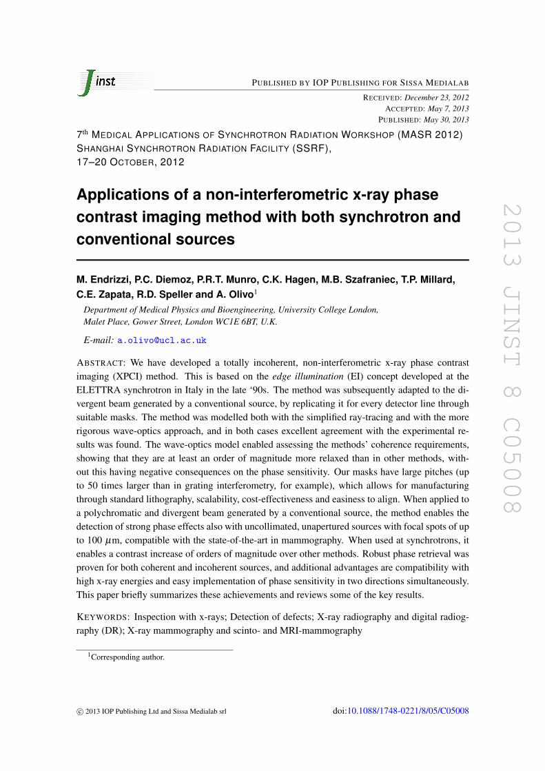
Figure 3 Phase retrieval in edge illumination x-ray phase contrast imaging (a) and (b) show the two maskconfigurations required to acquire two images that can be processed to extract phase and absorption (c)shows profiles extracted from the images of three thin wires (from left to right 100 microm Al 200 microm PEEKand 100 microm PEEK) imaged in the two configurations Relative intensity is plotted as a function of spatialdisplacement in mm
Figure 4 Retrieved absorption (a) and differential phase (b) images of a small onion (sim2 cm) obtained witha temporally and spatially incoherent source operated at 35 kVp and 25 mA
having negative consequences on the phase sensitivity [23 34] A robust phase-retrieval methodwas developed based on the processing of two images acquired while illuminating opposite sidesof the apertures on the detector mask (see figure 3)
The two symmetric mask configurations result in inverting the differential phase signal whileleaving absorption unchanged again in perfect analogy with analyser based imaging by looking atthe profiles in figure 3c one can immediately spot the similarity with images of the same samplesacquired on the two sides of the crystal reflectivity curve in analyser based imaging [26] Howeverby applying appropriate corrections for the extended source size in our case the method was shownto provide reliable quantitative results also with spatially and temporally incoherent sources [34]Figure 4 shows an example of ldquoincoherentrdquo phase and absorption separation obtained with the UCLMo-based system
This retrieval method was extended to include a correction for the gradient of absorptionwhich enables precise phase retrieval also for strongly absorbing objects This algorithm refinement
ndash 5 ndash
2013 JINST 8 C05008
Figure 5 CT implementation of the edge-illumination method (a) photograph of the used wire sample (b)reconstruction of the absorption signal (c) reconstruction of the phase gradient signal (d) reconstruction ofthe ldquomixedrdquo signal (see text)
also enables reliable phase retrieval along the edges of details where the very high gradients in theδ values cause other retrieval algorithms to break down [29 34] Effectively in reference [34] wecarry out a direct comparison between phase profiles of the same samples retrieved at synchrotronsand with conventional sources showing that at least for the simple objects examined in that casecomparable results are obtained
The method was used to image a variety of samples including breast tissue murine cartilageexplosives fossils small animals defects and blemishes in composite materials mdash demonstratingin all cases high contrast increases over conventional x-ray methods Following the developmentof the phase retrieval algorithm which gives access to quantitative information the method wasextended to CT one example is shown in figure 5
Alongside the reconstruction of phase and absorption signals figure 5 also shows the optionto reconstruct a ldquomixedrdquo CT volume (figure 5d) where every voxel contains a weighted average ofphase and absorption as recently demonstrated by Diemoz et al [35] This enables reconstructinga reliable 3D volume with enhanced detail visibility with a single CT acquisition over 180o Asrecently discussed by Zhu et al [36] rotation over 360o would again enable separating phase andabsorption as the two ldquosymmetricrdquo 180o series of projections effectively correspond to two separate180o acquisitions with the pre-sample mask in the two positions shown in figures 3a and 3b
Finally when used with coherent sources (eg synchrotrons) the methodrsquos flexibility and ca-pacity to ldquoamplifyrdquo the phase contrast by reducing the illuminated fraction of the pixels allowssignificant contrast increases over other XPCI methods This was recently demonstrated at theESRF where we obtained contrast values between 20 and 30 times higher than free-space propa-gation XPCI at very high x-ray energy (85 keV [25]) This concept was then translated to othersynchrotrons setups and different energy ranges constantly demonstrating substantially increasedsensitivity this topic is discussed in detail in the contribution by Diemoz et al in this same volume
4 Conclusions
This paper briefly reviews some of our recent achievements with the edge illumination XPCImethod When implemented with conventional x-ray sources the method provides intense phasecontrast signal and quantitative phase retrieval with focal spots of up to at least 100 microm (with-out this imposing large source-to-sample distances) With coherent sources (eg synchrotrons) itenables contrast (and thus sensitivity) amplification over other XPCI approaches The method is
ndash 6 ndash
2013 JINST 8 C05008
simple robust effective at very high x-ray energies [24 25] and resilient to environmental vibra-tions The implementation with conventional sources is based on the realization of x-ray maskswhich are cheap easy to fabricate and scalable to large sizes Their graphite substrates are prac-tically x-ray transparent and only one such substrate is placed downstream of the sample Thepre-sample mask can be used to prevent to a good extent the delivery of unwanted dose (for ex-ample by using small lateral displacements between pre-sample and detector mask) and the useof relatively large apertures in thin gold layers means that almost no angular filtration is applied tothe divergent beam (eg in our case the beam intensity does not ldquodroprdquo at the sides of the field ofview because of higher mask absorption for photons emitted at increasing angles with respect to theoptical axis) This results in a highly efficient use of the flux generated by the source potentiallymaking this the technology of choice for clinicalindustrial translations of XPCI While so far wehave been focusing mostly on the technical development of the method with only limited biomed-ical applications demonstrated so far [23] the next stages of our research will be dedicated directlyto the validation of the method on a range of significant applications in medicine and biology Onthe other hand we will also be further developing synchrotron implementations as the increasedsensitivity could be used to explore new scientific applications that are currently inaccessible
Acknowledgments
This work is funded by the UK Engineering and Physical Sciences Research Council (GrantsEPG0042501 and EPI0218841)
References
[1] M Born and E Wolf Principles of optics 6th edition Pergamon Press Oxford UK (1980)
[2] A Snigirev et al On the possibilities of x-ray phase contrast microimaging by coherent high-energysynchrotron radiation Rev Sci Instrum 66 (1995) 5486
[3] SW Wilkins et al Phase-contrast imaging using polychromatic hard x-rays Nature 384 (1996) 335
[4] E Forster K Goetz and P Zamumseil Double crystal diffractometry for the characterization oftargets for laser fusion experiments Krist Tech 15 (1980) 937
[5] T J Davis et al Phase-contrast imaging of weakly absorbing materials using hard x-rays Nature373 (1995) 595
[6] VN Ingal and EA Beliaevskaya X-ray plane-wave topography observation of the phase contrastfrom a non-crystalline object J Phys D 28 (1995) 2314
[7] F Arfelli et al Low-dose phase-contrast x-ray medical imaging Phys Med Biol 43 (1998) 2845
[8] A Olivo Towards the exploitation of phase effects in clinical synchrotron radiation radiology NuclInstrum Meth A 548 (2005) 194
[9] A Olivo and R Speller Experimental validation of a simple model capable of predicting the phasecontrast imaging capabilities of an x-ray imaging system Phys Med Biol 51 (2006) 3015
[10] T Gureyev et al Some simple rules for contrast signal-to-noise and resolution in in-line x-ray phasecontrast imaging Opt Express 16 (2008) 3223
[11] T Gureyev et al Refracting Rontgenrsquos rays propagation-based x-ray phase contrast for biomedicalimaging J Appl Phys 105 (2009) 102005
ndash 7 ndash
2013 JINST 8 C05008
[12] D Vine et al Analyzer-based phase contrast imaging and phase retrieval using a rotating anodex-ray source Appl Phys Lett 91 (2007) 254110
[13] A Olivo et al An innovative digital imaging set-up allowing a low-dose approach to phase contrastapplications in the medical field Med Phys 28 (2001) 1610
[14] A Olivo and R Speller A coded-aperture approach allowing x-ray phase contrast imaging withconventional sources Appl Phys Lett 91 (2007) 074106
[15] A Olivo and R Speller Modelling of a novel x-ray phase contrast imaging technique based on codedapertures Phys Med Biol 52 (2007) 6555
[16] C David B Nohammer HH Solak and E Ziegler Differential x-ray phase contrast imaging usinga shearing interferometer Appl Phys Lett 81 (2002) 3287
[17] A Momose et al Demonstration of x-ray Talbot interferometry Jpn J Appl Phys 42 (2003) L866
[18] T Weitkamp et al X-ray phase imaging with a grating interferometer Opt Express 13 (2005) 6296
[19] W B Case M Tomandl S Dechapunya and M Arndt Realization of optical carpets in the Talbotand Talbot-Lau configurations Opt Express 17 (2009) 20966
[20] F Pfeiffer T Weitkamp O Bunk and C David Phase retrieval and differential phase-contrastimaging with low-brilliance x-ray sources Nat Phys 2 (2006) 258
[21] J Zambelli N Bevins Z Qi and GH Chen Radiation dose efficiency comparison betweendifferential phase contrast CT and conventional absorption CT Med Phys 37 (2010) 2473
[22] A Olivo K Ignatyev PRT Munro and R Speller Noninterferometric phase-contrast imagesobtained with incoherent x-ray sources Appl Opt 50 (2011) 1765
[23] M Marenzana et al Visualization of small lesions in rat cartilage by means of laboratory-basedx-ray phase contrast imaging Phys Med Biol 57 (2012) 8173
[24] K Ignatyev et al Coded apertures allow high-energy x-ray phase contrast imaging with laboratorysources J Appl Phys 110 (2011) 014906
[25] A Olivo P C Diemoz and A Bravin Amplification of the phase contrast signal at very high x-rayenergies Opt Lett 37 (2012) 915
[26] D Chapman et al Diffraction enhanced x-ray imaging Phys Med Biol 42 (1997) 2015
[27] A Olivo and R Speller Image formation principles in coded-aperture based x-ray phase contrastimaging Phys Med Biol 53 (2008) 6461
[28] P R T Munro et al ldquoEdge illuminationrdquo in x-ray phase contrast imaging AIP Conf Proc 1446(2012) 118
[29] PRT Munro et al A quantitative non-interferometric x-ray phase contrast imaging technique OptExpress 21 (2013) 647
[30] A Olivo et al A non-free-space propagation x-ray phase contrast imaging method sensitive to phaseeffects in two directions simultaneously Appl Phys Lett 94 (2009) 044108
[31] K Ignatyev PRT Munro RD Speller and A Olivo Effects of signal diffusion on x-ray phasecontrast images Rev Sci Instrum 82 (2011) 073702
[32] P R T Munro K Ignatyev R D Speller and A Olivo The relationship between wave andgeometrical optics models of code aperture type x-ray phase contrast imaging systems Opt Express18 (2010) 4103
[33] PRT Munro K Ignatyev RD Speller and A Olivo Source size and temporal coherencerequirements of coded aperture type x-ray phase contrast imaging systems Opt Express 18 (2010)19681
ndash 8 ndash
2013 JINST 8 C05008
[34] PRT Munro K Ignatyev RD Speller and A Olivo Phase and absorption retrieval usingincoherent x-ray sources Proc Natl Acad Sci USA 109 (2012) 13922
[35] PC Diemoz et al A simplified approach for computed tomography with an x-ray gratinginterferometer Opt Express 19 (2011) 1691
[36] P Zhu et al Low-dose simple and fast grating-based x-ray phase-contrast imaging Proc NatlAcad Sci USA 107 (2010) 13576
ndash 9 ndash
- Introduction
- Materials and methods
- Results
- Conclusions
-
2013 JINST 8 C05008
PUBLISHED BY IOP PUBLISHING FOR SISSA MEDIALAB
RECEIVED December 23 2012ACCEPTED May 7 2013
PUBLISHED May 30 2013
7th MEDICAL APPLICATIONS OF SYNCHROTRON RADIATION WORKSHOP (MASR 2012)SHANGHAI SYNCHROTRON RADIATION FACILITY (SSRF)17ndash20 OCTOBER 2012
Applications of a non-interferometric x-ray phasecontrast imaging method with both synchrotron andconventional sources
M Endrizzi PC Diemoz PRT Munro CK Hagen MB Szafraniec TP MillardCE Zapata RD Speller and A Olivo1
Department of Medical Physics and Bioengineering University College LondonMalet Place Gower Street London WC1E 6BT UK
E-mail aolivouclacuk
ABSTRACT We have developed a totally incoherent non-interferometric x-ray phase contrastimaging (XPCI) method This is based on the edge illumination (EI) concept developed at theELETTRA synchrotron in Italy in the late lsquo90s The method was subsequently adapted to the di-vergent beam generated by a conventional source by replicating it for every detector line throughsuitable masks The method was modelled both with the simplified ray-tracing and with the morerigorous wave-optics approach and in both cases excellent agreement with the experimental re-sults was found The wave-optics model enabled assessing the methodsrsquo coherence requirementsshowing that they are at least an order of magnitude more relaxed than in other methods with-out this having negative consequences on the phase sensitivity Our masks have large pitches (upto 50 times larger than in grating interferometry for example) which allows for manufacturingthrough standard lithography scalability cost-effectiveness and easiness to align When applied toa polychromatic and divergent beam generated by a conventional source the method enables thedetection of strong phase effects also with uncollimated unapertured sources with focal spots of upto 100 microm compatible with the state-of-the-art in mammography When used at synchrotrons itenables a contrast increase of orders of magnitude over other methods Robust phase retrieval wasproven for both coherent and incoherent sources and additional advantages are compatibility withhigh x-ray energies and easy implementation of phase sensitivity in two directions simultaneouslyThis paper briefly summarizes these achievements and reviews some of the key results
KEYWORDS Inspection with x-rays Detection of defects X-ray radiography and digital radiog-raphy (DR) X-ray mammography and scinto- and MRI-mammography
1Corresponding author
ccopy 2013 IOP Publishing Ltd and Sissa Medialab srl doi1010881748-0221805C05008
2013 JINST 8 C05008
Contents
1 Introduction 1
2 Materials and methods 2
3 Results 4
4 Conclusions 6
1 Introduction
X-ray phase contrast imaging (XPCI) exploits interference and refraction effects (ldquophaserdquo effectshence the name) instead of attenuation to generate image contrast By doing this it both enhancesthe visibility of all detail in an x-ray image and it enables the visualization of features classicallyconsidered x-ray invisible due to lack of attenuation contrast The rationale behind this is thatconsidering the real and imaginary parts of the refractive index n [1]
n = 1minusδ + iβ (11)
it can be noted that the unit decrement of the real part δ (responsible for phase effects) is muchlarger than the imaginary part β (responsible for attenuation) typically up to 1000 times larger formost materials and over a wide range of x-ray energies
Initially this was exploited either through free space propagation [2 3] or perfect crystals(ldquoanalyser basedrdquo imaging [4ndash6]) This works very well with synchrotron x-ray beams whichtypically possess both spatial and temporal coherence Outside synchrotrons effective implemen-tations of XPCI become more difficult Free-space propagation methods tolerate relaxed temporalcoherence conditions [3] but suffer strongly from reductions in spatial coherence as the source di-mensions are made larger phase effects rapidly vanish [7ndash11] This means that microfocal sourcescan be used as an alternative to synchrotrons but at the price of long exposure times (hours [3])due to their low emitted flux Crystal methods on the other hand can tolerate a relaxed degree ofspatial coherence [12] but intrinsically impose high temporal coherence as the crystal automati-cally selects a narrow bandwidth out of the spectrum emitted by the source
In the late nineties we were trying to solve this conundrum at the SYRMEP (SynchrotronRadiation for MEdical Physics) beamline of the ELETTRA synchrotron in Trieste Italy by com-bining the aspects of free-space propagation that make it resilient to reduced temporal coherencewith those that enable crystal methods to tolerate somewhat relaxed spatial coherence The latteraspect is due to the fact that crystals can be seen as very effective angular filters and can thus beused to exploit refraction effects with high accuracy However having to employ a crystal practi-cally forces the use of monochromatic radiation The goal was therefore to develop an approachthat could perform a fine angular selection on refracted x-rays without employing a crystal This
ndash 1 ndash
2013 JINST 8 C05008
Figure 1 The basic implementation of the edge illumination method with synchrotron radiation
was achieved by means of the edge illumination (EI) method which consists in illuminating onlythe edges of the detector pixels [13] In this way small deviations in the x-ray direction are suffi-cient to deflect x-rays out of the detector active surface causing dark fringes and vice-versa (seefigure 1) Images with a strong similarity to those provided by analyser based imaging are obtainedin this way [13] but the absence of the crystal makes the method amenable to divergent and poly-chromatic beams This is achieved by means of two aperture masks [14 15] placed one beforeand one after the imaged sample (sometimes referred to as ldquocoded aperturesrdquo although they differsignificantly from those used in nuclear medicine or astronomy) which enable repeating the EIconfiguration for every row (or column) of pixel in an area detector (see figure 2 below)
It should be noted that despite some superficial similarity in the setup with grating (or ldquoshear-ingrdquo or ldquoTalbotrdquo) interferometry [16ndash18] the method is based on a different physical principle (EIinstead of Talbot self-imaging) and is in fact a totally incoherent method while grating interfer-ometry still requires at least spatial coherence which (in the TalbotLau configuration [19]) canalso be achieved through the introduction of the ldquosourcerdquo grating [20]
While in grating interferometry the gratings have pitches of the order of a few micron thusrequiring highly specialized fabrication facilities and very fine alignments (of down to a few tensof nm [21]) our masks have pitches up to 50 times larger which allows for manufacturing throughstandard lithography scalability cost-effectiveness and easiness to align The larger pitch togetherwith the fact that stepping one mask with respect to the other is not required relaxes the alignmentrequirements to a couple of microm [22] Moreover the pre-sample mask (see figure 2) protects thesample from unwanted radiation enabling the achievement of clinically acceptable doses [23]
Most importantly this set-up provides strong phase contrast signals with focal spots of up to100 microm [15] compatible with current state-of-the-art mammography sources without requiringexcessive source-to-sample distances Together with the fact that the full unfiltered polychromaticbeam produced by a Mo [14 15 23] or a W [22 24] source can be used this means that oursis the first XPCI method working with sources that are simultaneously incoherent both spatiallyand temporally Despite this phase sensitivity at least equivalent to that of grating interferometersoperated on the 3rd Talbot order was recently demonstrated [23]
2 Materials and methods
In its basic synchrotron implementation the EI method is extremely simple (see figure 1)All it requires is beam pre-shaping through a slit (the vertical aperture of which determines the
phase sensitivity together with the sample to detector distance [13 15]) and a ldquosensitivity edgerdquoon the detector surface If a ldquolinearrdquo detector consisting of a single row of pixels is availablethe edge of the pixel row itself can be used (like in figure 1) With a more conventional detector a
ndash 2 ndash
2013 JINST 8 C05008
Figure 2 Extension of the edge illumination method to larger beam cross-sections (a) and (b) show the par-allel (typically synchrotron) and divergent (typically conventional source) beam configurations respectively
polished absorbing edge (eg made of tungsten carbide) can be mounted in front of the detector andaligned with a row of pixels to create a sharp transition between sensitive and insensitive detectorareas [25] The beam collimated by the ldquoshapingrdquo slit is then positioned such that it straddles theedge between sensitive and insensitive regions on the detector In this synchrotron setup where thebeam is often very thin in the vertical direction samples are typically scanned through the beam toobtain the two-dimensional images In our case the sample is scanned immediately downstreamof the ldquoshapingrdquo slit During this scan when one of the details in the sample touches the upperpart of the beam it can refract x-rays downwards (with respect to figure 1) These x-rays whichwould normally miss the pixel are thus counted The number of counts corresponding to thatsample position would therefore be increased creating a bright fringe along that side of the detailLikewise when the detail grazes the bottom part of the beam x-rays that are normally counted canbe deviated upwards and thus possibly miss the detector creating a negative fringe ldquoDifferentialrdquo(ie proportional to the first derivative of the phase shift) XPCI images are obtained in this way justlike the ones obtained on one side of the reflectivity curve of an analyser crystal [26] Although inour case the differential nature is due to the convolution of ldquohalfrdquo a free-space propagation profilewith the pixel response function [27 28] it can be shown that by optimizing beam thickness andsample-to-detector distance so that comparable phase sensitivity is achieved results effectivelyequivalent to analyser based imaging are obtained [13]
The edge illumination concept is easily extended to larger beam cross-sections by means ofmasks Figure 2 shows possible embodiments for a parallel beam (figure 2a) eg a vertically largersynchrotron beam and for a divergent beam originated from a conventional source (figure 2b) Thelatter simply requires rescaling the pre-sample mask to account for the beam divergence In bothcases the sample is placed immediately downstream of the pre-sample mask An additional mask(or series of beam-stops) is placed in contact with the detector to create insensitive regions be-tween adjacent pixels which allow realizing the EI condition The availability of a plurality ofbeams allows avoiding sample scanning however ldquoditheringrdquo (ie interweaving more images ac-quired while displacing the sample by sub-pixel quantities) enables overcoming the resolution limitimposed by the pixel size [15 22] The fact that the detector mask redefines the response function
ndash 3 ndash
2013 JINST 8 C05008
of the detector pixel (effectively shrinking its point spread function) means that the application ofdeconvolution methods is not required provided the dithering step is larger than or equal to theapertures in the detector mask
While the system represented in figure 1 is used at various synchrotrons including ELET-TRA [29] the ESRF [25] and Diamond (see Diemoz et al paper in this volume) using either setsof Huber slits or the beamline air slits as pre-sample beam shapers and polished tungsten edges asbeam stops two systems based on conventional sources (figure 2b) are currently in operation inour labs at UCL One is based on a Rigaku M007 Mo source with a focal spot of approximately 70microm typically operated at 25 mA and 35 or 40 kVp This is used primarily for medical and biolog-ical applications and it uses the ANRAD ldquoSMAMrdquo a-Se flat panel detector which has a pixel sizeof 85 microm The other system is based on an X-Tek W source with a focal spot of 50 microm operatedbetween 40 and 100 keV and at 1 mA and it features the Hamamatsu C9732DK CMOS-based flatpanel detector with a 50 microm pixel This is typically used for industrial and material science appli-cations Different sets of masks are available for both systems with apertures shaped like long slitsmatching detector columns (or rows) or like ldquoLrsquosrdquo matching each detector pixel for simultaneoustwo-directional phase sensitivity [30] In all cases gold layers between 30 and 200 microm in thicknessare electroplated on thin low absorbing graphite substrates All masks were manufactured to theauthorsrsquo design by Creatv Microtech (Potomac MD) While all detector masks for the Mo systemhave a pitch matching the ANRAD pixel size (85 microm) masks with pitches of both 50 microm (ldquonon-skippingrdquo masks) and 100 microm (ldquoskippingrdquo masks) are available for the W system corresponding toonce and twice the pixel pitch of the Hamamatsu detector respectively Being an indirect detectionsystem the Hamamatsu detector features significant signal spillover between adjacent pixels Withour method this results in a contrast reduction for non-dithered images and can result in artefactsfor dithered images [31] The problem is solved by using a detector mask with twice the pixelpitch as the spillover into the second neighbour is negligible This has a price to pay in terms ofresolution which can be overcome by dithering however the acquisition time increases with thedithering steps Hence non-skipping masks are used when resolution and shorter acquisition timesare more important than contrast maximization This problem does not apply to the Mo systemas the signal spillover is almost negligible for the ANRAD which is a direct conversion detectorhence only non-skipping masks are used All masks are mounted on stacks of Newport translatorsand Kohzu cradles for alignment Samples are mounted on an additional translation stage whichis used either to perform sample ldquoditheringrdquo or to move the sample out of the field of view whenflat field images are acquired The sample stage on the Mo system also features a rotary stage toperform CT acquisitions this is mounted on two cradles that are used to align the axis of rotationwith the detector columns An upgrade is currently underway to have the same feature availablealso in the W system
3 Results
The method was modelled both with the simplified ray-tracing [13 15] and with the more rigorouswave-optics approach [32] and in both cases excellent agreement with the experimental results wasfound The wave-optics model enabled assessing the methodrsquos coherence requirements showingthat they are at least one order of magnitude more relaxed than in other approaches [33] without this
ndash 4 ndash
2013 JINST 8 C05008
Figure 3 Phase retrieval in edge illumination x-ray phase contrast imaging (a) and (b) show the two maskconfigurations required to acquire two images that can be processed to extract phase and absorption (c)shows profiles extracted from the images of three thin wires (from left to right 100 microm Al 200 microm PEEKand 100 microm PEEK) imaged in the two configurations Relative intensity is plotted as a function of spatialdisplacement in mm
Figure 4 Retrieved absorption (a) and differential phase (b) images of a small onion (sim2 cm) obtained witha temporally and spatially incoherent source operated at 35 kVp and 25 mA
having negative consequences on the phase sensitivity [23 34] A robust phase-retrieval methodwas developed based on the processing of two images acquired while illuminating opposite sidesof the apertures on the detector mask (see figure 3)
The two symmetric mask configurations result in inverting the differential phase signal whileleaving absorption unchanged again in perfect analogy with analyser based imaging by looking atthe profiles in figure 3c one can immediately spot the similarity with images of the same samplesacquired on the two sides of the crystal reflectivity curve in analyser based imaging [26] Howeverby applying appropriate corrections for the extended source size in our case the method was shownto provide reliable quantitative results also with spatially and temporally incoherent sources [34]Figure 4 shows an example of ldquoincoherentrdquo phase and absorption separation obtained with the UCLMo-based system
This retrieval method was extended to include a correction for the gradient of absorptionwhich enables precise phase retrieval also for strongly absorbing objects This algorithm refinement
ndash 5 ndash
2013 JINST 8 C05008
Figure 5 CT implementation of the edge-illumination method (a) photograph of the used wire sample (b)reconstruction of the absorption signal (c) reconstruction of the phase gradient signal (d) reconstruction ofthe ldquomixedrdquo signal (see text)
also enables reliable phase retrieval along the edges of details where the very high gradients in theδ values cause other retrieval algorithms to break down [29 34] Effectively in reference [34] wecarry out a direct comparison between phase profiles of the same samples retrieved at synchrotronsand with conventional sources showing that at least for the simple objects examined in that casecomparable results are obtained
The method was used to image a variety of samples including breast tissue murine cartilageexplosives fossils small animals defects and blemishes in composite materials mdash demonstratingin all cases high contrast increases over conventional x-ray methods Following the developmentof the phase retrieval algorithm which gives access to quantitative information the method wasextended to CT one example is shown in figure 5
Alongside the reconstruction of phase and absorption signals figure 5 also shows the optionto reconstruct a ldquomixedrdquo CT volume (figure 5d) where every voxel contains a weighted average ofphase and absorption as recently demonstrated by Diemoz et al [35] This enables reconstructinga reliable 3D volume with enhanced detail visibility with a single CT acquisition over 180o Asrecently discussed by Zhu et al [36] rotation over 360o would again enable separating phase andabsorption as the two ldquosymmetricrdquo 180o series of projections effectively correspond to two separate180o acquisitions with the pre-sample mask in the two positions shown in figures 3a and 3b
Finally when used with coherent sources (eg synchrotrons) the methodrsquos flexibility and ca-pacity to ldquoamplifyrdquo the phase contrast by reducing the illuminated fraction of the pixels allowssignificant contrast increases over other XPCI methods This was recently demonstrated at theESRF where we obtained contrast values between 20 and 30 times higher than free-space propa-gation XPCI at very high x-ray energy (85 keV [25]) This concept was then translated to othersynchrotrons setups and different energy ranges constantly demonstrating substantially increasedsensitivity this topic is discussed in detail in the contribution by Diemoz et al in this same volume
4 Conclusions
This paper briefly reviews some of our recent achievements with the edge illumination XPCImethod When implemented with conventional x-ray sources the method provides intense phasecontrast signal and quantitative phase retrieval with focal spots of up to at least 100 microm (with-out this imposing large source-to-sample distances) With coherent sources (eg synchrotrons) itenables contrast (and thus sensitivity) amplification over other XPCI approaches The method is
ndash 6 ndash
2013 JINST 8 C05008
simple robust effective at very high x-ray energies [24 25] and resilient to environmental vibra-tions The implementation with conventional sources is based on the realization of x-ray maskswhich are cheap easy to fabricate and scalable to large sizes Their graphite substrates are prac-tically x-ray transparent and only one such substrate is placed downstream of the sample Thepre-sample mask can be used to prevent to a good extent the delivery of unwanted dose (for ex-ample by using small lateral displacements between pre-sample and detector mask) and the useof relatively large apertures in thin gold layers means that almost no angular filtration is applied tothe divergent beam (eg in our case the beam intensity does not ldquodroprdquo at the sides of the field ofview because of higher mask absorption for photons emitted at increasing angles with respect to theoptical axis) This results in a highly efficient use of the flux generated by the source potentiallymaking this the technology of choice for clinicalindustrial translations of XPCI While so far wehave been focusing mostly on the technical development of the method with only limited biomed-ical applications demonstrated so far [23] the next stages of our research will be dedicated directlyto the validation of the method on a range of significant applications in medicine and biology Onthe other hand we will also be further developing synchrotron implementations as the increasedsensitivity could be used to explore new scientific applications that are currently inaccessible
Acknowledgments
This work is funded by the UK Engineering and Physical Sciences Research Council (GrantsEPG0042501 and EPI0218841)
References
[1] M Born and E Wolf Principles of optics 6th edition Pergamon Press Oxford UK (1980)
[2] A Snigirev et al On the possibilities of x-ray phase contrast microimaging by coherent high-energysynchrotron radiation Rev Sci Instrum 66 (1995) 5486
[3] SW Wilkins et al Phase-contrast imaging using polychromatic hard x-rays Nature 384 (1996) 335
[4] E Forster K Goetz and P Zamumseil Double crystal diffractometry for the characterization oftargets for laser fusion experiments Krist Tech 15 (1980) 937
[5] T J Davis et al Phase-contrast imaging of weakly absorbing materials using hard x-rays Nature373 (1995) 595
[6] VN Ingal and EA Beliaevskaya X-ray plane-wave topography observation of the phase contrastfrom a non-crystalline object J Phys D 28 (1995) 2314
[7] F Arfelli et al Low-dose phase-contrast x-ray medical imaging Phys Med Biol 43 (1998) 2845
[8] A Olivo Towards the exploitation of phase effects in clinical synchrotron radiation radiology NuclInstrum Meth A 548 (2005) 194
[9] A Olivo and R Speller Experimental validation of a simple model capable of predicting the phasecontrast imaging capabilities of an x-ray imaging system Phys Med Biol 51 (2006) 3015
[10] T Gureyev et al Some simple rules for contrast signal-to-noise and resolution in in-line x-ray phasecontrast imaging Opt Express 16 (2008) 3223
[11] T Gureyev et al Refracting Rontgenrsquos rays propagation-based x-ray phase contrast for biomedicalimaging J Appl Phys 105 (2009) 102005
ndash 7 ndash
2013 JINST 8 C05008
[12] D Vine et al Analyzer-based phase contrast imaging and phase retrieval using a rotating anodex-ray source Appl Phys Lett 91 (2007) 254110
[13] A Olivo et al An innovative digital imaging set-up allowing a low-dose approach to phase contrastapplications in the medical field Med Phys 28 (2001) 1610
[14] A Olivo and R Speller A coded-aperture approach allowing x-ray phase contrast imaging withconventional sources Appl Phys Lett 91 (2007) 074106
[15] A Olivo and R Speller Modelling of a novel x-ray phase contrast imaging technique based on codedapertures Phys Med Biol 52 (2007) 6555
[16] C David B Nohammer HH Solak and E Ziegler Differential x-ray phase contrast imaging usinga shearing interferometer Appl Phys Lett 81 (2002) 3287
[17] A Momose et al Demonstration of x-ray Talbot interferometry Jpn J Appl Phys 42 (2003) L866
[18] T Weitkamp et al X-ray phase imaging with a grating interferometer Opt Express 13 (2005) 6296
[19] W B Case M Tomandl S Dechapunya and M Arndt Realization of optical carpets in the Talbotand Talbot-Lau configurations Opt Express 17 (2009) 20966
[20] F Pfeiffer T Weitkamp O Bunk and C David Phase retrieval and differential phase-contrastimaging with low-brilliance x-ray sources Nat Phys 2 (2006) 258
[21] J Zambelli N Bevins Z Qi and GH Chen Radiation dose efficiency comparison betweendifferential phase contrast CT and conventional absorption CT Med Phys 37 (2010) 2473
[22] A Olivo K Ignatyev PRT Munro and R Speller Noninterferometric phase-contrast imagesobtained with incoherent x-ray sources Appl Opt 50 (2011) 1765
[23] M Marenzana et al Visualization of small lesions in rat cartilage by means of laboratory-basedx-ray phase contrast imaging Phys Med Biol 57 (2012) 8173
[24] K Ignatyev et al Coded apertures allow high-energy x-ray phase contrast imaging with laboratorysources J Appl Phys 110 (2011) 014906
[25] A Olivo P C Diemoz and A Bravin Amplification of the phase contrast signal at very high x-rayenergies Opt Lett 37 (2012) 915
[26] D Chapman et al Diffraction enhanced x-ray imaging Phys Med Biol 42 (1997) 2015
[27] A Olivo and R Speller Image formation principles in coded-aperture based x-ray phase contrastimaging Phys Med Biol 53 (2008) 6461
[28] P R T Munro et al ldquoEdge illuminationrdquo in x-ray phase contrast imaging AIP Conf Proc 1446(2012) 118
[29] PRT Munro et al A quantitative non-interferometric x-ray phase contrast imaging technique OptExpress 21 (2013) 647
[30] A Olivo et al A non-free-space propagation x-ray phase contrast imaging method sensitive to phaseeffects in two directions simultaneously Appl Phys Lett 94 (2009) 044108
[31] K Ignatyev PRT Munro RD Speller and A Olivo Effects of signal diffusion on x-ray phasecontrast images Rev Sci Instrum 82 (2011) 073702
[32] P R T Munro K Ignatyev R D Speller and A Olivo The relationship between wave andgeometrical optics models of code aperture type x-ray phase contrast imaging systems Opt Express18 (2010) 4103
[33] PRT Munro K Ignatyev RD Speller and A Olivo Source size and temporal coherencerequirements of coded aperture type x-ray phase contrast imaging systems Opt Express 18 (2010)19681
ndash 8 ndash
2013 JINST 8 C05008
[34] PRT Munro K Ignatyev RD Speller and A Olivo Phase and absorption retrieval usingincoherent x-ray sources Proc Natl Acad Sci USA 109 (2012) 13922
[35] PC Diemoz et al A simplified approach for computed tomography with an x-ray gratinginterferometer Opt Express 19 (2011) 1691
[36] P Zhu et al Low-dose simple and fast grating-based x-ray phase-contrast imaging Proc NatlAcad Sci USA 107 (2010) 13576
ndash 9 ndash
- Introduction
- Materials and methods
- Results
- Conclusions
-

2013 JINST 8 C05008
Figure 2 Extension of the edge illumination method to larger beam cross-sections (a) and (b) show the par-allel (typically synchrotron) and divergent (typically conventional source) beam configurations respectively
polished absorbing edge (eg made of tungsten carbide) can be mounted in front of the detector andaligned with a row of pixels to create a sharp transition between sensitive and insensitive detectorareas [25] The beam collimated by the ldquoshapingrdquo slit is then positioned such that it straddles theedge between sensitive and insensitive regions on the detector In this synchrotron setup where thebeam is often very thin in the vertical direction samples are typically scanned through the beam toobtain the two-dimensional images In our case the sample is scanned immediately downstreamof the ldquoshapingrdquo slit During this scan when one of the details in the sample touches the upperpart of the beam it can refract x-rays downwards (with respect to figure 1) These x-rays whichwould normally miss the pixel are thus counted The number of counts corresponding to thatsample position would therefore be increased creating a bright fringe along that side of the detailLikewise when the detail grazes the bottom part of the beam x-rays that are normally counted canbe deviated upwards and thus possibly miss the detector creating a negative fringe ldquoDifferentialrdquo(ie proportional to the first derivative of the phase shift) XPCI images are obtained in this way justlike the ones obtained on one side of the reflectivity curve of an analyser crystal [26] Although inour case the differential nature is due to the convolution of ldquohalfrdquo a free-space propagation profilewith the pixel response function [27 28] it can be shown that by optimizing beam thickness andsample-to-detector distance so that comparable phase sensitivity is achieved results effectivelyequivalent to analyser based imaging are obtained [13]
The edge illumination concept is easily extended to larger beam cross-sections by means ofmasks Figure 2 shows possible embodiments for a parallel beam (figure 2a) eg a vertically largersynchrotron beam and for a divergent beam originated from a conventional source (figure 2b) Thelatter simply requires rescaling the pre-sample mask to account for the beam divergence In bothcases the sample is placed immediately downstream of the pre-sample mask An additional mask(or series of beam-stops) is placed in contact with the detector to create insensitive regions be-tween adjacent pixels which allow realizing the EI condition The availability of a plurality ofbeams allows avoiding sample scanning however ldquoditheringrdquo (ie interweaving more images ac-quired while displacing the sample by sub-pixel quantities) enables overcoming the resolution limitimposed by the pixel size [15 22] The fact that the detector mask redefines the response function
ndash 3 ndash
2013 JINST 8 C05008
of the detector pixel (effectively shrinking its point spread function) means that the application ofdeconvolution methods is not required provided the dithering step is larger than or equal to theapertures in the detector mask
While the system represented in figure 1 is used at various synchrotrons including ELET-TRA [29] the ESRF [25] and Diamond (see Diemoz et al paper in this volume) using either setsof Huber slits or the beamline air slits as pre-sample beam shapers and polished tungsten edges asbeam stops two systems based on conventional sources (figure 2b) are currently in operation inour labs at UCL One is based on a Rigaku M007 Mo source with a focal spot of approximately 70microm typically operated at 25 mA and 35 or 40 kVp This is used primarily for medical and biolog-ical applications and it uses the ANRAD ldquoSMAMrdquo a-Se flat panel detector which has a pixel sizeof 85 microm The other system is based on an X-Tek W source with a focal spot of 50 microm operatedbetween 40 and 100 keV and at 1 mA and it features the Hamamatsu C9732DK CMOS-based flatpanel detector with a 50 microm pixel This is typically used for industrial and material science appli-cations Different sets of masks are available for both systems with apertures shaped like long slitsmatching detector columns (or rows) or like ldquoLrsquosrdquo matching each detector pixel for simultaneoustwo-directional phase sensitivity [30] In all cases gold layers between 30 and 200 microm in thicknessare electroplated on thin low absorbing graphite substrates All masks were manufactured to theauthorsrsquo design by Creatv Microtech (Potomac MD) While all detector masks for the Mo systemhave a pitch matching the ANRAD pixel size (85 microm) masks with pitches of both 50 microm (ldquonon-skippingrdquo masks) and 100 microm (ldquoskippingrdquo masks) are available for the W system corresponding toonce and twice the pixel pitch of the Hamamatsu detector respectively Being an indirect detectionsystem the Hamamatsu detector features significant signal spillover between adjacent pixels Withour method this results in a contrast reduction for non-dithered images and can result in artefactsfor dithered images [31] The problem is solved by using a detector mask with twice the pixelpitch as the spillover into the second neighbour is negligible This has a price to pay in terms ofresolution which can be overcome by dithering however the acquisition time increases with thedithering steps Hence non-skipping masks are used when resolution and shorter acquisition timesare more important than contrast maximization This problem does not apply to the Mo systemas the signal spillover is almost negligible for the ANRAD which is a direct conversion detectorhence only non-skipping masks are used All masks are mounted on stacks of Newport translatorsand Kohzu cradles for alignment Samples are mounted on an additional translation stage whichis used either to perform sample ldquoditheringrdquo or to move the sample out of the field of view whenflat field images are acquired The sample stage on the Mo system also features a rotary stage toperform CT acquisitions this is mounted on two cradles that are used to align the axis of rotationwith the detector columns An upgrade is currently underway to have the same feature availablealso in the W system
3 Results
The method was modelled both with the simplified ray-tracing [13 15] and with the more rigorouswave-optics approach [32] and in both cases excellent agreement with the experimental results wasfound The wave-optics model enabled assessing the methodrsquos coherence requirements showingthat they are at least one order of magnitude more relaxed than in other approaches [33] without this
ndash 4 ndash
2013 JINST 8 C05008
Figure 3 Phase retrieval in edge illumination x-ray phase contrast imaging (a) and (b) show the two maskconfigurations required to acquire two images that can be processed to extract phase and absorption (c)shows profiles extracted from the images of three thin wires (from left to right 100 microm Al 200 microm PEEKand 100 microm PEEK) imaged in the two configurations Relative intensity is plotted as a function of spatialdisplacement in mm
Figure 4 Retrieved absorption (a) and differential phase (b) images of a small onion (sim2 cm) obtained witha temporally and spatially incoherent source operated at 35 kVp and 25 mA
having negative consequences on the phase sensitivity [23 34] A robust phase-retrieval methodwas developed based on the processing of two images acquired while illuminating opposite sidesof the apertures on the detector mask (see figure 3)
The two symmetric mask configurations result in inverting the differential phase signal whileleaving absorption unchanged again in perfect analogy with analyser based imaging by looking atthe profiles in figure 3c one can immediately spot the similarity with images of the same samplesacquired on the two sides of the crystal reflectivity curve in analyser based imaging [26] Howeverby applying appropriate corrections for the extended source size in our case the method was shownto provide reliable quantitative results also with spatially and temporally incoherent sources [34]Figure 4 shows an example of ldquoincoherentrdquo phase and absorption separation obtained with the UCLMo-based system
This retrieval method was extended to include a correction for the gradient of absorptionwhich enables precise phase retrieval also for strongly absorbing objects This algorithm refinement
ndash 5 ndash
2013 JINST 8 C05008
Figure 5 CT implementation of the edge-illumination method (a) photograph of the used wire sample (b)reconstruction of the absorption signal (c) reconstruction of the phase gradient signal (d) reconstruction ofthe ldquomixedrdquo signal (see text)
also enables reliable phase retrieval along the edges of details where the very high gradients in theδ values cause other retrieval algorithms to break down [29 34] Effectively in reference [34] wecarry out a direct comparison between phase profiles of the same samples retrieved at synchrotronsand with conventional sources showing that at least for the simple objects examined in that casecomparable results are obtained
The method was used to image a variety of samples including breast tissue murine cartilageexplosives fossils small animals defects and blemishes in composite materials mdash demonstratingin all cases high contrast increases over conventional x-ray methods Following the developmentof the phase retrieval algorithm which gives access to quantitative information the method wasextended to CT one example is shown in figure 5
Alongside the reconstruction of phase and absorption signals figure 5 also shows the optionto reconstruct a ldquomixedrdquo CT volume (figure 5d) where every voxel contains a weighted average ofphase and absorption as recently demonstrated by Diemoz et al [35] This enables reconstructinga reliable 3D volume with enhanced detail visibility with a single CT acquisition over 180o Asrecently discussed by Zhu et al [36] rotation over 360o would again enable separating phase andabsorption as the two ldquosymmetricrdquo 180o series of projections effectively correspond to two separate180o acquisitions with the pre-sample mask in the two positions shown in figures 3a and 3b
Finally when used with coherent sources (eg synchrotrons) the methodrsquos flexibility and ca-pacity to ldquoamplifyrdquo the phase contrast by reducing the illuminated fraction of the pixels allowssignificant contrast increases over other XPCI methods This was recently demonstrated at theESRF where we obtained contrast values between 20 and 30 times higher than free-space propa-gation XPCI at very high x-ray energy (85 keV [25]) This concept was then translated to othersynchrotrons setups and different energy ranges constantly demonstrating substantially increasedsensitivity this topic is discussed in detail in the contribution by Diemoz et al in this same volume
4 Conclusions
This paper briefly reviews some of our recent achievements with the edge illumination XPCImethod When implemented with conventional x-ray sources the method provides intense phasecontrast signal and quantitative phase retrieval with focal spots of up to at least 100 microm (with-out this imposing large source-to-sample distances) With coherent sources (eg synchrotrons) itenables contrast (and thus sensitivity) amplification over other XPCI approaches The method is
ndash 6 ndash
2013 JINST 8 C05008
simple robust effective at very high x-ray energies [24 25] and resilient to environmental vibra-tions The implementation with conventional sources is based on the realization of x-ray maskswhich are cheap easy to fabricate and scalable to large sizes Their graphite substrates are prac-tically x-ray transparent and only one such substrate is placed downstream of the sample Thepre-sample mask can be used to prevent to a good extent the delivery of unwanted dose (for ex-ample by using small lateral displacements between pre-sample and detector mask) and the useof relatively large apertures in thin gold layers means that almost no angular filtration is applied tothe divergent beam (eg in our case the beam intensity does not ldquodroprdquo at the sides of the field ofview because of higher mask absorption for photons emitted at increasing angles with respect to theoptical axis) This results in a highly efficient use of the flux generated by the source potentiallymaking this the technology of choice for clinicalindustrial translations of XPCI While so far wehave been focusing mostly on the technical development of the method with only limited biomed-ical applications demonstrated so far [23] the next stages of our research will be dedicated directlyto the validation of the method on a range of significant applications in medicine and biology Onthe other hand we will also be further developing synchrotron implementations as the increasedsensitivity could be used to explore new scientific applications that are currently inaccessible
Acknowledgments
This work is funded by the UK Engineering and Physical Sciences Research Council (GrantsEPG0042501 and EPI0218841)
References
[1] M Born and E Wolf Principles of optics 6th edition Pergamon Press Oxford UK (1980)
[2] A Snigirev et al On the possibilities of x-ray phase contrast microimaging by coherent high-energysynchrotron radiation Rev Sci Instrum 66 (1995) 5486
[3] SW Wilkins et al Phase-contrast imaging using polychromatic hard x-rays Nature 384 (1996) 335
[4] E Forster K Goetz and P Zamumseil Double crystal diffractometry for the characterization oftargets for laser fusion experiments Krist Tech 15 (1980) 937
[5] T J Davis et al Phase-contrast imaging of weakly absorbing materials using hard x-rays Nature373 (1995) 595
[6] VN Ingal and EA Beliaevskaya X-ray plane-wave topography observation of the phase contrastfrom a non-crystalline object J Phys D 28 (1995) 2314
[7] F Arfelli et al Low-dose phase-contrast x-ray medical imaging Phys Med Biol 43 (1998) 2845
[8] A Olivo Towards the exploitation of phase effects in clinical synchrotron radiation radiology NuclInstrum Meth A 548 (2005) 194
[9] A Olivo and R Speller Experimental validation of a simple model capable of predicting the phasecontrast imaging capabilities of an x-ray imaging system Phys Med Biol 51 (2006) 3015
[10] T Gureyev et al Some simple rules for contrast signal-to-noise and resolution in in-line x-ray phasecontrast imaging Opt Express 16 (2008) 3223
[11] T Gureyev et al Refracting Rontgenrsquos rays propagation-based x-ray phase contrast for biomedicalimaging J Appl Phys 105 (2009) 102005
ndash 7 ndash
2013 JINST 8 C05008
[12] D Vine et al Analyzer-based phase contrast imaging and phase retrieval using a rotating anodex-ray source Appl Phys Lett 91 (2007) 254110
[13] A Olivo et al An innovative digital imaging set-up allowing a low-dose approach to phase contrastapplications in the medical field Med Phys 28 (2001) 1610
[14] A Olivo and R Speller A coded-aperture approach allowing x-ray phase contrast imaging withconventional sources Appl Phys Lett 91 (2007) 074106
[15] A Olivo and R Speller Modelling of a novel x-ray phase contrast imaging technique based on codedapertures Phys Med Biol 52 (2007) 6555
[16] C David B Nohammer HH Solak and E Ziegler Differential x-ray phase contrast imaging usinga shearing interferometer Appl Phys Lett 81 (2002) 3287
[17] A Momose et al Demonstration of x-ray Talbot interferometry Jpn J Appl Phys 42 (2003) L866
[18] T Weitkamp et al X-ray phase imaging with a grating interferometer Opt Express 13 (2005) 6296
[19] W B Case M Tomandl S Dechapunya and M Arndt Realization of optical carpets in the Talbotand Talbot-Lau configurations Opt Express 17 (2009) 20966
[20] F Pfeiffer T Weitkamp O Bunk and C David Phase retrieval and differential phase-contrastimaging with low-brilliance x-ray sources Nat Phys 2 (2006) 258
[21] J Zambelli N Bevins Z Qi and GH Chen Radiation dose efficiency comparison betweendifferential phase contrast CT and conventional absorption CT Med Phys 37 (2010) 2473
[22] A Olivo K Ignatyev PRT Munro and R Speller Noninterferometric phase-contrast imagesobtained with incoherent x-ray sources Appl Opt 50 (2011) 1765
[23] M Marenzana et al Visualization of small lesions in rat cartilage by means of laboratory-basedx-ray phase contrast imaging Phys Med Biol 57 (2012) 8173
[24] K Ignatyev et al Coded apertures allow high-energy x-ray phase contrast imaging with laboratorysources J Appl Phys 110 (2011) 014906
[25] A Olivo P C Diemoz and A Bravin Amplification of the phase contrast signal at very high x-rayenergies Opt Lett 37 (2012) 915
[26] D Chapman et al Diffraction enhanced x-ray imaging Phys Med Biol 42 (1997) 2015
[27] A Olivo and R Speller Image formation principles in coded-aperture based x-ray phase contrastimaging Phys Med Biol 53 (2008) 6461
[28] P R T Munro et al ldquoEdge illuminationrdquo in x-ray phase contrast imaging AIP Conf Proc 1446(2012) 118
[29] PRT Munro et al A quantitative non-interferometric x-ray phase contrast imaging technique OptExpress 21 (2013) 647
[30] A Olivo et al A non-free-space propagation x-ray phase contrast imaging method sensitive to phaseeffects in two directions simultaneously Appl Phys Lett 94 (2009) 044108
[31] K Ignatyev PRT Munro RD Speller and A Olivo Effects of signal diffusion on x-ray phasecontrast images Rev Sci Instrum 82 (2011) 073702
[32] P R T Munro K Ignatyev R D Speller and A Olivo The relationship between wave andgeometrical optics models of code aperture type x-ray phase contrast imaging systems Opt Express18 (2010) 4103
[33] PRT Munro K Ignatyev RD Speller and A Olivo Source size and temporal coherencerequirements of coded aperture type x-ray phase contrast imaging systems Opt Express 18 (2010)19681
ndash 8 ndash
2013 JINST 8 C05008
[34] PRT Munro K Ignatyev RD Speller and A Olivo Phase and absorption retrieval usingincoherent x-ray sources Proc Natl Acad Sci USA 109 (2012) 13922
[35] PC Diemoz et al A simplified approach for computed tomography with an x-ray gratinginterferometer Opt Express 19 (2011) 1691
[36] P Zhu et al Low-dose simple and fast grating-based x-ray phase-contrast imaging Proc NatlAcad Sci USA 107 (2010) 13576
ndash 9 ndash
- Introduction
- Materials and methods
- Results
- Conclusions
-
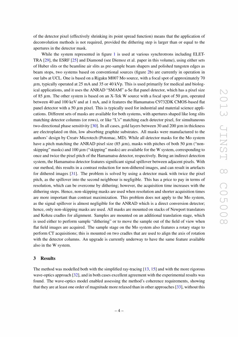
2013 JINST 8 C05008
of the detector pixel (effectively shrinking its point spread function) means that the application ofdeconvolution methods is not required provided the dithering step is larger than or equal to theapertures in the detector mask
While the system represented in figure 1 is used at various synchrotrons including ELET-TRA [29] the ESRF [25] and Diamond (see Diemoz et al paper in this volume) using either setsof Huber slits or the beamline air slits as pre-sample beam shapers and polished tungsten edges asbeam stops two systems based on conventional sources (figure 2b) are currently in operation inour labs at UCL One is based on a Rigaku M007 Mo source with a focal spot of approximately 70microm typically operated at 25 mA and 35 or 40 kVp This is used primarily for medical and biolog-ical applications and it uses the ANRAD ldquoSMAMrdquo a-Se flat panel detector which has a pixel sizeof 85 microm The other system is based on an X-Tek W source with a focal spot of 50 microm operatedbetween 40 and 100 keV and at 1 mA and it features the Hamamatsu C9732DK CMOS-based flatpanel detector with a 50 microm pixel This is typically used for industrial and material science appli-cations Different sets of masks are available for both systems with apertures shaped like long slitsmatching detector columns (or rows) or like ldquoLrsquosrdquo matching each detector pixel for simultaneoustwo-directional phase sensitivity [30] In all cases gold layers between 30 and 200 microm in thicknessare electroplated on thin low absorbing graphite substrates All masks were manufactured to theauthorsrsquo design by Creatv Microtech (Potomac MD) While all detector masks for the Mo systemhave a pitch matching the ANRAD pixel size (85 microm) masks with pitches of both 50 microm (ldquonon-skippingrdquo masks) and 100 microm (ldquoskippingrdquo masks) are available for the W system corresponding toonce and twice the pixel pitch of the Hamamatsu detector respectively Being an indirect detectionsystem the Hamamatsu detector features significant signal spillover between adjacent pixels Withour method this results in a contrast reduction for non-dithered images and can result in artefactsfor dithered images [31] The problem is solved by using a detector mask with twice the pixelpitch as the spillover into the second neighbour is negligible This has a price to pay in terms ofresolution which can be overcome by dithering however the acquisition time increases with thedithering steps Hence non-skipping masks are used when resolution and shorter acquisition timesare more important than contrast maximization This problem does not apply to the Mo systemas the signal spillover is almost negligible for the ANRAD which is a direct conversion detectorhence only non-skipping masks are used All masks are mounted on stacks of Newport translatorsand Kohzu cradles for alignment Samples are mounted on an additional translation stage whichis used either to perform sample ldquoditheringrdquo or to move the sample out of the field of view whenflat field images are acquired The sample stage on the Mo system also features a rotary stage toperform CT acquisitions this is mounted on two cradles that are used to align the axis of rotationwith the detector columns An upgrade is currently underway to have the same feature availablealso in the W system
3 Results
The method was modelled both with the simplified ray-tracing [13 15] and with the more rigorouswave-optics approach [32] and in both cases excellent agreement with the experimental results wasfound The wave-optics model enabled assessing the methodrsquos coherence requirements showingthat they are at least one order of magnitude more relaxed than in other approaches [33] without this
ndash 4 ndash
2013 JINST 8 C05008
Figure 3 Phase retrieval in edge illumination x-ray phase contrast imaging (a) and (b) show the two maskconfigurations required to acquire two images that can be processed to extract phase and absorption (c)shows profiles extracted from the images of three thin wires (from left to right 100 microm Al 200 microm PEEKand 100 microm PEEK) imaged in the two configurations Relative intensity is plotted as a function of spatialdisplacement in mm
Figure 4 Retrieved absorption (a) and differential phase (b) images of a small onion (sim2 cm) obtained witha temporally and spatially incoherent source operated at 35 kVp and 25 mA
having negative consequences on the phase sensitivity [23 34] A robust phase-retrieval methodwas developed based on the processing of two images acquired while illuminating opposite sidesof the apertures on the detector mask (see figure 3)
The two symmetric mask configurations result in inverting the differential phase signal whileleaving absorption unchanged again in perfect analogy with analyser based imaging by looking atthe profiles in figure 3c one can immediately spot the similarity with images of the same samplesacquired on the two sides of the crystal reflectivity curve in analyser based imaging [26] Howeverby applying appropriate corrections for the extended source size in our case the method was shownto provide reliable quantitative results also with spatially and temporally incoherent sources [34]Figure 4 shows an example of ldquoincoherentrdquo phase and absorption separation obtained with the UCLMo-based system
This retrieval method was extended to include a correction for the gradient of absorptionwhich enables precise phase retrieval also for strongly absorbing objects This algorithm refinement
ndash 5 ndash
2013 JINST 8 C05008
Figure 5 CT implementation of the edge-illumination method (a) photograph of the used wire sample (b)reconstruction of the absorption signal (c) reconstruction of the phase gradient signal (d) reconstruction ofthe ldquomixedrdquo signal (see text)
also enables reliable phase retrieval along the edges of details where the very high gradients in theδ values cause other retrieval algorithms to break down [29 34] Effectively in reference [34] wecarry out a direct comparison between phase profiles of the same samples retrieved at synchrotronsand with conventional sources showing that at least for the simple objects examined in that casecomparable results are obtained
The method was used to image a variety of samples including breast tissue murine cartilageexplosives fossils small animals defects and blemishes in composite materials mdash demonstratingin all cases high contrast increases over conventional x-ray methods Following the developmentof the phase retrieval algorithm which gives access to quantitative information the method wasextended to CT one example is shown in figure 5
Alongside the reconstruction of phase and absorption signals figure 5 also shows the optionto reconstruct a ldquomixedrdquo CT volume (figure 5d) where every voxel contains a weighted average ofphase and absorption as recently demonstrated by Diemoz et al [35] This enables reconstructinga reliable 3D volume with enhanced detail visibility with a single CT acquisition over 180o Asrecently discussed by Zhu et al [36] rotation over 360o would again enable separating phase andabsorption as the two ldquosymmetricrdquo 180o series of projections effectively correspond to two separate180o acquisitions with the pre-sample mask in the two positions shown in figures 3a and 3b
Finally when used with coherent sources (eg synchrotrons) the methodrsquos flexibility and ca-pacity to ldquoamplifyrdquo the phase contrast by reducing the illuminated fraction of the pixels allowssignificant contrast increases over other XPCI methods This was recently demonstrated at theESRF where we obtained contrast values between 20 and 30 times higher than free-space propa-gation XPCI at very high x-ray energy (85 keV [25]) This concept was then translated to othersynchrotrons setups and different energy ranges constantly demonstrating substantially increasedsensitivity this topic is discussed in detail in the contribution by Diemoz et al in this same volume
4 Conclusions
This paper briefly reviews some of our recent achievements with the edge illumination XPCImethod When implemented with conventional x-ray sources the method provides intense phasecontrast signal and quantitative phase retrieval with focal spots of up to at least 100 microm (with-out this imposing large source-to-sample distances) With coherent sources (eg synchrotrons) itenables contrast (and thus sensitivity) amplification over other XPCI approaches The method is
ndash 6 ndash
2013 JINST 8 C05008
simple robust effective at very high x-ray energies [24 25] and resilient to environmental vibra-tions The implementation with conventional sources is based on the realization of x-ray maskswhich are cheap easy to fabricate and scalable to large sizes Their graphite substrates are prac-tically x-ray transparent and only one such substrate is placed downstream of the sample Thepre-sample mask can be used to prevent to a good extent the delivery of unwanted dose (for ex-ample by using small lateral displacements between pre-sample and detector mask) and the useof relatively large apertures in thin gold layers means that almost no angular filtration is applied tothe divergent beam (eg in our case the beam intensity does not ldquodroprdquo at the sides of the field ofview because of higher mask absorption for photons emitted at increasing angles with respect to theoptical axis) This results in a highly efficient use of the flux generated by the source potentiallymaking this the technology of choice for clinicalindustrial translations of XPCI While so far wehave been focusing mostly on the technical development of the method with only limited biomed-ical applications demonstrated so far [23] the next stages of our research will be dedicated directlyto the validation of the method on a range of significant applications in medicine and biology Onthe other hand we will also be further developing synchrotron implementations as the increasedsensitivity could be used to explore new scientific applications that are currently inaccessible
Acknowledgments
This work is funded by the UK Engineering and Physical Sciences Research Council (GrantsEPG0042501 and EPI0218841)
References
[1] M Born and E Wolf Principles of optics 6th edition Pergamon Press Oxford UK (1980)
[2] A Snigirev et al On the possibilities of x-ray phase contrast microimaging by coherent high-energysynchrotron radiation Rev Sci Instrum 66 (1995) 5486
[3] SW Wilkins et al Phase-contrast imaging using polychromatic hard x-rays Nature 384 (1996) 335
[4] E Forster K Goetz and P Zamumseil Double crystal diffractometry for the characterization oftargets for laser fusion experiments Krist Tech 15 (1980) 937
[5] T J Davis et al Phase-contrast imaging of weakly absorbing materials using hard x-rays Nature373 (1995) 595
[6] VN Ingal and EA Beliaevskaya X-ray plane-wave topography observation of the phase contrastfrom a non-crystalline object J Phys D 28 (1995) 2314
[7] F Arfelli et al Low-dose phase-contrast x-ray medical imaging Phys Med Biol 43 (1998) 2845
[8] A Olivo Towards the exploitation of phase effects in clinical synchrotron radiation radiology NuclInstrum Meth A 548 (2005) 194
[9] A Olivo and R Speller Experimental validation of a simple model capable of predicting the phasecontrast imaging capabilities of an x-ray imaging system Phys Med Biol 51 (2006) 3015
[10] T Gureyev et al Some simple rules for contrast signal-to-noise and resolution in in-line x-ray phasecontrast imaging Opt Express 16 (2008) 3223
[11] T Gureyev et al Refracting Rontgenrsquos rays propagation-based x-ray phase contrast for biomedicalimaging J Appl Phys 105 (2009) 102005
ndash 7 ndash
2013 JINST 8 C05008
[12] D Vine et al Analyzer-based phase contrast imaging and phase retrieval using a rotating anodex-ray source Appl Phys Lett 91 (2007) 254110
[13] A Olivo et al An innovative digital imaging set-up allowing a low-dose approach to phase contrastapplications in the medical field Med Phys 28 (2001) 1610
[14] A Olivo and R Speller A coded-aperture approach allowing x-ray phase contrast imaging withconventional sources Appl Phys Lett 91 (2007) 074106
[15] A Olivo and R Speller Modelling of a novel x-ray phase contrast imaging technique based on codedapertures Phys Med Biol 52 (2007) 6555
[16] C David B Nohammer HH Solak and E Ziegler Differential x-ray phase contrast imaging usinga shearing interferometer Appl Phys Lett 81 (2002) 3287
[17] A Momose et al Demonstration of x-ray Talbot interferometry Jpn J Appl Phys 42 (2003) L866
[18] T Weitkamp et al X-ray phase imaging with a grating interferometer Opt Express 13 (2005) 6296
[19] W B Case M Tomandl S Dechapunya and M Arndt Realization of optical carpets in the Talbotand Talbot-Lau configurations Opt Express 17 (2009) 20966
[20] F Pfeiffer T Weitkamp O Bunk and C David Phase retrieval and differential phase-contrastimaging with low-brilliance x-ray sources Nat Phys 2 (2006) 258
[21] J Zambelli N Bevins Z Qi and GH Chen Radiation dose efficiency comparison betweendifferential phase contrast CT and conventional absorption CT Med Phys 37 (2010) 2473
[22] A Olivo K Ignatyev PRT Munro and R Speller Noninterferometric phase-contrast imagesobtained with incoherent x-ray sources Appl Opt 50 (2011) 1765
[23] M Marenzana et al Visualization of small lesions in rat cartilage by means of laboratory-basedx-ray phase contrast imaging Phys Med Biol 57 (2012) 8173
[24] K Ignatyev et al Coded apertures allow high-energy x-ray phase contrast imaging with laboratorysources J Appl Phys 110 (2011) 014906
[25] A Olivo P C Diemoz and A Bravin Amplification of the phase contrast signal at very high x-rayenergies Opt Lett 37 (2012) 915
[26] D Chapman et al Diffraction enhanced x-ray imaging Phys Med Biol 42 (1997) 2015
[27] A Olivo and R Speller Image formation principles in coded-aperture based x-ray phase contrastimaging Phys Med Biol 53 (2008) 6461
[28] P R T Munro et al ldquoEdge illuminationrdquo in x-ray phase contrast imaging AIP Conf Proc 1446(2012) 118
[29] PRT Munro et al A quantitative non-interferometric x-ray phase contrast imaging technique OptExpress 21 (2013) 647
[30] A Olivo et al A non-free-space propagation x-ray phase contrast imaging method sensitive to phaseeffects in two directions simultaneously Appl Phys Lett 94 (2009) 044108
[31] K Ignatyev PRT Munro RD Speller and A Olivo Effects of signal diffusion on x-ray phasecontrast images Rev Sci Instrum 82 (2011) 073702
[32] P R T Munro K Ignatyev R D Speller and A Olivo The relationship between wave andgeometrical optics models of code aperture type x-ray phase contrast imaging systems Opt Express18 (2010) 4103
[33] PRT Munro K Ignatyev RD Speller and A Olivo Source size and temporal coherencerequirements of coded aperture type x-ray phase contrast imaging systems Opt Express 18 (2010)19681
ndash 8 ndash
2013 JINST 8 C05008
[34] PRT Munro K Ignatyev RD Speller and A Olivo Phase and absorption retrieval usingincoherent x-ray sources Proc Natl Acad Sci USA 109 (2012) 13922
[35] PC Diemoz et al A simplified approach for computed tomography with an x-ray gratinginterferometer Opt Express 19 (2011) 1691
[36] P Zhu et al Low-dose simple and fast grating-based x-ray phase-contrast imaging Proc NatlAcad Sci USA 107 (2010) 13576
ndash 9 ndash
- Introduction
- Materials and methods
- Results
- Conclusions
-
2013 JINST 8 C05008
Figure 3 Phase retrieval in edge illumination x-ray phase contrast imaging (a) and (b) show the two maskconfigurations required to acquire two images that can be processed to extract phase and absorption (c)shows profiles extracted from the images of three thin wires (from left to right 100 microm Al 200 microm PEEKand 100 microm PEEK) imaged in the two configurations Relative intensity is plotted as a function of spatialdisplacement in mm
Figure 4 Retrieved absorption (a) and differential phase (b) images of a small onion (sim2 cm) obtained witha temporally and spatially incoherent source operated at 35 kVp and 25 mA
having negative consequences on the phase sensitivity [23 34] A robust phase-retrieval methodwas developed based on the processing of two images acquired while illuminating opposite sidesof the apertures on the detector mask (see figure 3)
The two symmetric mask configurations result in inverting the differential phase signal whileleaving absorption unchanged again in perfect analogy with analyser based imaging by looking atthe profiles in figure 3c one can immediately spot the similarity with images of the same samplesacquired on the two sides of the crystal reflectivity curve in analyser based imaging [26] Howeverby applying appropriate corrections for the extended source size in our case the method was shownto provide reliable quantitative results also with spatially and temporally incoherent sources [34]Figure 4 shows an example of ldquoincoherentrdquo phase and absorption separation obtained with the UCLMo-based system
This retrieval method was extended to include a correction for the gradient of absorptionwhich enables precise phase retrieval also for strongly absorbing objects This algorithm refinement
ndash 5 ndash
2013 JINST 8 C05008
Figure 5 CT implementation of the edge-illumination method (a) photograph of the used wire sample (b)reconstruction of the absorption signal (c) reconstruction of the phase gradient signal (d) reconstruction ofthe ldquomixedrdquo signal (see text)
also enables reliable phase retrieval along the edges of details where the very high gradients in theδ values cause other retrieval algorithms to break down [29 34] Effectively in reference [34] wecarry out a direct comparison between phase profiles of the same samples retrieved at synchrotronsand with conventional sources showing that at least for the simple objects examined in that casecomparable results are obtained
The method was used to image a variety of samples including breast tissue murine cartilageexplosives fossils small animals defects and blemishes in composite materials mdash demonstratingin all cases high contrast increases over conventional x-ray methods Following the developmentof the phase retrieval algorithm which gives access to quantitative information the method wasextended to CT one example is shown in figure 5
Alongside the reconstruction of phase and absorption signals figure 5 also shows the optionto reconstruct a ldquomixedrdquo CT volume (figure 5d) where every voxel contains a weighted average ofphase and absorption as recently demonstrated by Diemoz et al [35] This enables reconstructinga reliable 3D volume with enhanced detail visibility with a single CT acquisition over 180o Asrecently discussed by Zhu et al [36] rotation over 360o would again enable separating phase andabsorption as the two ldquosymmetricrdquo 180o series of projections effectively correspond to two separate180o acquisitions with the pre-sample mask in the two positions shown in figures 3a and 3b
Finally when used with coherent sources (eg synchrotrons) the methodrsquos flexibility and ca-pacity to ldquoamplifyrdquo the phase contrast by reducing the illuminated fraction of the pixels allowssignificant contrast increases over other XPCI methods This was recently demonstrated at theESRF where we obtained contrast values between 20 and 30 times higher than free-space propa-gation XPCI at very high x-ray energy (85 keV [25]) This concept was then translated to othersynchrotrons setups and different energy ranges constantly demonstrating substantially increasedsensitivity this topic is discussed in detail in the contribution by Diemoz et al in this same volume
4 Conclusions
This paper briefly reviews some of our recent achievements with the edge illumination XPCImethod When implemented with conventional x-ray sources the method provides intense phasecontrast signal and quantitative phase retrieval with focal spots of up to at least 100 microm (with-out this imposing large source-to-sample distances) With coherent sources (eg synchrotrons) itenables contrast (and thus sensitivity) amplification over other XPCI approaches The method is
ndash 6 ndash
2013 JINST 8 C05008
simple robust effective at very high x-ray energies [24 25] and resilient to environmental vibra-tions The implementation with conventional sources is based on the realization of x-ray maskswhich are cheap easy to fabricate and scalable to large sizes Their graphite substrates are prac-tically x-ray transparent and only one such substrate is placed downstream of the sample Thepre-sample mask can be used to prevent to a good extent the delivery of unwanted dose (for ex-ample by using small lateral displacements between pre-sample and detector mask) and the useof relatively large apertures in thin gold layers means that almost no angular filtration is applied tothe divergent beam (eg in our case the beam intensity does not ldquodroprdquo at the sides of the field ofview because of higher mask absorption for photons emitted at increasing angles with respect to theoptical axis) This results in a highly efficient use of the flux generated by the source potentiallymaking this the technology of choice for clinicalindustrial translations of XPCI While so far wehave been focusing mostly on the technical development of the method with only limited biomed-ical applications demonstrated so far [23] the next stages of our research will be dedicated directlyto the validation of the method on a range of significant applications in medicine and biology Onthe other hand we will also be further developing synchrotron implementations as the increasedsensitivity could be used to explore new scientific applications that are currently inaccessible
Acknowledgments
This work is funded by the UK Engineering and Physical Sciences Research Council (GrantsEPG0042501 and EPI0218841)
References
[1] M Born and E Wolf Principles of optics 6th edition Pergamon Press Oxford UK (1980)
[2] A Snigirev et al On the possibilities of x-ray phase contrast microimaging by coherent high-energysynchrotron radiation Rev Sci Instrum 66 (1995) 5486
[3] SW Wilkins et al Phase-contrast imaging using polychromatic hard x-rays Nature 384 (1996) 335
[4] E Forster K Goetz and P Zamumseil Double crystal diffractometry for the characterization oftargets for laser fusion experiments Krist Tech 15 (1980) 937
[5] T J Davis et al Phase-contrast imaging of weakly absorbing materials using hard x-rays Nature373 (1995) 595
[6] VN Ingal and EA Beliaevskaya X-ray plane-wave topography observation of the phase contrastfrom a non-crystalline object J Phys D 28 (1995) 2314
[7] F Arfelli et al Low-dose phase-contrast x-ray medical imaging Phys Med Biol 43 (1998) 2845
[8] A Olivo Towards the exploitation of phase effects in clinical synchrotron radiation radiology NuclInstrum Meth A 548 (2005) 194
[9] A Olivo and R Speller Experimental validation of a simple model capable of predicting the phasecontrast imaging capabilities of an x-ray imaging system Phys Med Biol 51 (2006) 3015
[10] T Gureyev et al Some simple rules for contrast signal-to-noise and resolution in in-line x-ray phasecontrast imaging Opt Express 16 (2008) 3223
[11] T Gureyev et al Refracting Rontgenrsquos rays propagation-based x-ray phase contrast for biomedicalimaging J Appl Phys 105 (2009) 102005
ndash 7 ndash
2013 JINST 8 C05008
[12] D Vine et al Analyzer-based phase contrast imaging and phase retrieval using a rotating anodex-ray source Appl Phys Lett 91 (2007) 254110
[13] A Olivo et al An innovative digital imaging set-up allowing a low-dose approach to phase contrastapplications in the medical field Med Phys 28 (2001) 1610
[14] A Olivo and R Speller A coded-aperture approach allowing x-ray phase contrast imaging withconventional sources Appl Phys Lett 91 (2007) 074106
[15] A Olivo and R Speller Modelling of a novel x-ray phase contrast imaging technique based on codedapertures Phys Med Biol 52 (2007) 6555
[16] C David B Nohammer HH Solak and E Ziegler Differential x-ray phase contrast imaging usinga shearing interferometer Appl Phys Lett 81 (2002) 3287
[17] A Momose et al Demonstration of x-ray Talbot interferometry Jpn J Appl Phys 42 (2003) L866
[18] T Weitkamp et al X-ray phase imaging with a grating interferometer Opt Express 13 (2005) 6296
[19] W B Case M Tomandl S Dechapunya and M Arndt Realization of optical carpets in the Talbotand Talbot-Lau configurations Opt Express 17 (2009) 20966
[20] F Pfeiffer T Weitkamp O Bunk and C David Phase retrieval and differential phase-contrastimaging with low-brilliance x-ray sources Nat Phys 2 (2006) 258
[21] J Zambelli N Bevins Z Qi and GH Chen Radiation dose efficiency comparison betweendifferential phase contrast CT and conventional absorption CT Med Phys 37 (2010) 2473
[22] A Olivo K Ignatyev PRT Munro and R Speller Noninterferometric phase-contrast imagesobtained with incoherent x-ray sources Appl Opt 50 (2011) 1765
[23] M Marenzana et al Visualization of small lesions in rat cartilage by means of laboratory-basedx-ray phase contrast imaging Phys Med Biol 57 (2012) 8173
[24] K Ignatyev et al Coded apertures allow high-energy x-ray phase contrast imaging with laboratorysources J Appl Phys 110 (2011) 014906
[25] A Olivo P C Diemoz and A Bravin Amplification of the phase contrast signal at very high x-rayenergies Opt Lett 37 (2012) 915
[26] D Chapman et al Diffraction enhanced x-ray imaging Phys Med Biol 42 (1997) 2015
[27] A Olivo and R Speller Image formation principles in coded-aperture based x-ray phase contrastimaging Phys Med Biol 53 (2008) 6461
[28] P R T Munro et al ldquoEdge illuminationrdquo in x-ray phase contrast imaging AIP Conf Proc 1446(2012) 118
[29] PRT Munro et al A quantitative non-interferometric x-ray phase contrast imaging technique OptExpress 21 (2013) 647
[30] A Olivo et al A non-free-space propagation x-ray phase contrast imaging method sensitive to phaseeffects in two directions simultaneously Appl Phys Lett 94 (2009) 044108
[31] K Ignatyev PRT Munro RD Speller and A Olivo Effects of signal diffusion on x-ray phasecontrast images Rev Sci Instrum 82 (2011) 073702
[32] P R T Munro K Ignatyev R D Speller and A Olivo The relationship between wave andgeometrical optics models of code aperture type x-ray phase contrast imaging systems Opt Express18 (2010) 4103
[33] PRT Munro K Ignatyev RD Speller and A Olivo Source size and temporal coherencerequirements of coded aperture type x-ray phase contrast imaging systems Opt Express 18 (2010)19681
ndash 8 ndash
2013 JINST 8 C05008
[34] PRT Munro K Ignatyev RD Speller and A Olivo Phase and absorption retrieval usingincoherent x-ray sources Proc Natl Acad Sci USA 109 (2012) 13922
[35] PC Diemoz et al A simplified approach for computed tomography with an x-ray gratinginterferometer Opt Express 19 (2011) 1691
[36] P Zhu et al Low-dose simple and fast grating-based x-ray phase-contrast imaging Proc NatlAcad Sci USA 107 (2010) 13576
ndash 9 ndash
- Introduction
- Materials and methods
- Results
- Conclusions
-

2013 JINST 8 C05008
[34] PRT Munro K Ignatyev RD Speller and A Olivo Phase and absorption retrieval usingincoherent x-ray sources Proc Natl Acad Sci USA 109 (2012) 13922
[35] PC Diemoz et al A simplified approach for computed tomography with an x-ray gratinginterferometer Opt Express 19 (2011) 1691
[36] P Zhu et al Low-dose simple and fast grating-based x-ray phase-contrast imaging Proc NatlAcad Sci USA 107 (2010) 13576
ndash 9 ndash
- Introduction
- Materials and methods
- Results
- Conclusions
-