applications of advanced indentation technique to pre
TRANSCRIPT
Citation &
Copyright (to be inserted by the publisher)
Applications of Advanced Indentation Technique to Pre-Qualification and Periodic Monitoring of Strength
Performance of Industrial Structures
Yeol Choi1,2, Jae-il Jang1, Kwang-Ho Kim1, Dongil Kwon2 and Sang-Ki Park3
1 Frontics, Inc., Research Institute of Advanced Materials, Seoul National University,
Seoul 151-742, Korea 2 School of Materials Science and Engineering, Seoul National University,
Seoul 151-742, Korea 3 Power Generation Research Lab., Korea Electric Power Research Institute,
Daejon 305-380, Korea
Keywords: Advanced Indentation Technique, Tensile Properties, In-Service Inspection (ISI), Pre-Service Inspection (PSI), Pre-Qualification, Periodic Monitoring
Abstract. The demand for new in-field technology which can non-destructively evaluate the key
material properties has been increased for safe and economic operations of industrial
structures/facilities whose material properties can be significantly degraded during operation in
hostile environments. As a promising method to meet the needs, an advanced indentation technique is
suggested here. This novel technique can evaluate the true-stress-true-strain relationship and
quantitative tensile properties (such as yield strength, tensile strength and work-hardening exponent)
non-destructively by analyzing indentation load-depth curve. In this paper, two recent applications of
the indentation technique to pre- and in-service-inspection (PSI and ISI) of industrial structures are
introduced and discussed. First, pre-qualification of strength performance of welded joint in power
plant pipes is successfully performed using this indentation technique while conventional
pre-qualification of welded joints through other non-destructive techniques are just focusing on exact
crack detection. Second, it was proved that the advanced indentation technique has the strong
potential to be used for in-field periodic monitoring of strength change of oil/gas transmission
pipeline, which is required by new regulations for safe maintenance and economical repair.
Introduction
To prevent frequent failure of structural components by time-dependent degradation and a severe
operating environment, many kinds of non-destructive testing techniques (NDT), most of which are
focused on the detection of crack-type damage and microstructural change, have been developed.
However, there has been little NDT technique developed for direct measurement of mechanical
property change in industrial field. Although portable hardness testing equipments have provided
hardness value in field, the obtained hardness values cannot be applied to mechanical-design-based
integrity evaluations which need not the empirical value such as hardness but the exact tensile and
fracture properties. It is very clear that, if those kinds of the mechanical properties can be measured
non-destructively in field, the accuracy level and reliability of structural integrity will be significantly
enhanced. With the similar viewpoints, new regulations have been recently established. For example,
US-DOT (Department of Transportation)’s 49 CFR 192 specifies that one set of tensile tests have to
be done for each 10 unit lengths of pipe for pipelines of more than 100 pipe lengths [1]. But,
conventional standard tests for measuring the mechanical properties such as the uniaxial tensile and
the fracture toughness tests, which have the requirements of bulky-sized samples, cannot be used for
in-service components and local region such as welded joints, known as critical region of welded
structures.
Key Engineering Materials Vols. 270-273 (2004) pp. 1694-1699online at http://www.scientific.net© (2004) Trans Tech Publications, Switzerland
All rights reserved. No part of contents of this paper may be reproduced or transmitted in any form or by any means without thewritten permission of the publisher: Trans Tech Publications Ltd, Switzerland, www.ttp.net. (ID: 166.104.133.35-23/02/07,01:55:35)

Title of Publication (to be inserted by the publisher)
As the most promising NDT for measuring mechanical property in industrial fields, an advanced
indentation technique is introduced in this study. This technique, one of instrumented indentation
techniques, can measure the tensile properties (including the yield strength, work-hardening exponent
and ultimate tensile strength) almost non-destructively by analyzing indentation load vs. penetration
depth curve obtained during loading and unloading, without direct observation of indent size as like
conventional hardness test. This indentation load-depth curve represents the deformation behavior of
the test sample beneath the rigid ball indenter [2]. Additionally, the technique has lots of advantages
for in-field applications: (i) the indentation system is portable and easily attached to the components
in service, (ii) testing procedure is very simple and does not require tedious specimen preparation, (iii)
no damage remains after the tests.
In this paper, two interesting examples of the recent applications are introduced and discussed;
First, pre-qualification of strength performance of welded joint in power plant pipes under
construction, and second, in-field periodic monitoring of strength change of oil/gas transmission
pipeline, which is required by new regulations for safe maintenance and economical repair.
Theory of the advanced indentation technique
As the spherical indenter penetrates into material, mechanical deformation is divided as three stages
of elastic, elastic/plastic and fully plastic [3]. A reversible deformation occurs at low load indentation.
When the indentation stress fields satisfy the yield criterion, plastic zone occurs inside the material
and expands to free surface. And, the mean contact pressure beneath the spherical indenter rapidly
increases in this elastic/plastic region. Finally, the expanded hemi-spherical plastic zone grows into
the surrounding elastic zone with a constant velocity as the indentation depth increases. The mean
contact pressure slightly increases in this fully plastic region. These deformation stages are similar to
the work-hardening behavior of the uniaxial tensile test except for non-homogeneity.
Research for predicting the uniaxial flow properties from indentation-induced deformation was
performed as described below. The raw data from the advanced indentation test is the indentation
load-depth curve as shown in fig. 1.
Fig. 1. Schematic graph of the indentation load-depth curve.
The equivalent stress and strain were defined in terms of the measured indentation contact
parameters such as contact depth, hc*, indenter shape and the morphology of the deformed sample
surface. And, real contact properties were determined by considering both the elastic deflection and
the material pile-up around the contacting indenter.
First, a contact depth at maximum indentation load can be evaluated by analyzing the unloading
curve with the concept of indenter geometry and elastic deflection as shown in Eq. (1) [4].
)( maxmax*
ic hhhh −−−−−−−−==== ωωωω (1)
Key Engineering Materials Vols. 270-273 1695
Title of Publication (to be inserted by the publisher)
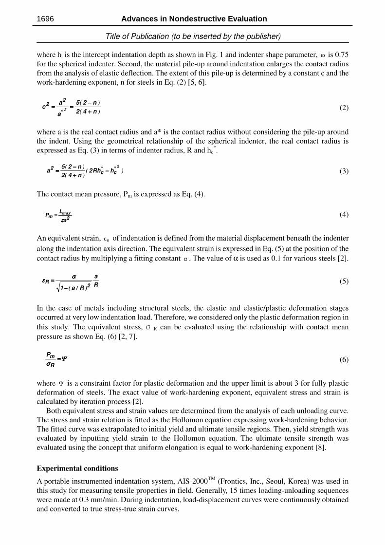
where hi is the intercept indentation depth as shown in Fig. 1 and indenter shape parameter, ω is 0.75
for the spherical indenter. Second, the material pile-up around indentation enlarges the contact radius
from the analysis of elastic deflection. The extent of this pile-up is determined by a constant c and the
work-hardening exponent, n for steels in Eq. (2) [5, 6].
)(
)(
* n42
n25
a
ac
2
22
++++
−−−−======== (2)
where a is the real contact radius and a* is the contact radius without considering the pile-up around
the indent. Using the geometrical relationship of the spherical indenter, the real contact radius is
expressed as Eq. (3) in terms of indenter radius, R and hc*.
)()(
)( **2
cc2
hRh2n42
n25a −−−−
++++
−−−−==== (3)
The contact mean pressure, Pm is expressed as Eq. (4).
2ma
LP
ππππ
max==== (4)
An equivalent strain, Rε of indentation is defined from the material displacement beneath the indenter
along the indentation axis direction. The equivalent strain is expressed in Eq. (5) at the position of the
contact radius by multiplying a fitting constant α . The value of α is used as 0.1 for various steels [2].
R
a
Ra12
R
)/(−−−−
====αααα
εεεε (5)
In the case of metals including structural steels, the elastic and elastic/plastic deformation stages
occurred at very low indentation load. Therefore, we considered only the plastic deformation region in
this study. The equivalent stress, σ R can be evaluated using the relationship with contact mean
pressure as shown Eq. (6) [2, 7].
ΨΨΨΨσσσσ
====R
mP (6)
where Ψ is a constraint factor for plastic deformation and the upper limit is about 3 for fully plastic
deformation of steels. The exact value of work-hardening exponent, equivalent stress and strain is
calculated by iteration process [2].
Both equivalent stress and strain values are determined from the analysis of each unloading curve.
The stress and strain relation is fitted as the Hollomon equation expressing work-hardening behavior.
The fitted curve was extrapolated to initial yield and ultimate tensile regions. Then, yield strength was
evaluated by inputting yield strain to the Hollomon equation. The ultimate tensile strength was
evaluated using the concept that uniform elongation is equal to work-hardening exponent [8].
Experimental conditions
A portable instrumented indentation system, AIS-2000TM (Frontics, Inc., Seoul, Korea) was used in
this study for measuring tensile properties in field. Generally, 15 times loading-unloading sequences
were made at 0.3 mm/min. During indentation, load-displacement curves were continuously obtained
and converted to true stress-true strain curves.
Advances in Nondestructive Evaluation1696

Title of Publication (to be inserted by the publisher)
The applied accuracy of the sensors used was 300 gf for load and 0.2 µm for displacement. The
LVDT is installed next to the indenter. The spherical WC indenter was an integrated part of the WC
stem which makes it possible to eliminate brazing of the WC indenter to the steel stem. With this type
of arrangement, the system compliance can be minimized. Since unreliable attachment of the system
to the pipeline could result in significant errors in load and displacement measurements, a pair of
curved magnets, along with mechanical chain or u-block, were used to firmly attach the system to the
pipe against the maximum load.
Results and Discussion
Application to Pre-service Inspection (PSI). In general, mechanical properties of weld joints have
been evaluated by only procedure qualification records (PQR), in which tensile tests at laboratory
were made using sample specimens with the same welding conditions as in-field. But it is difficult for
PQR to consider various constrain conditions and environments of in-field weldments during
construction. Therefore advanced indention tests were applied to inspect the strengths of pipeline
welded joints non-destructively at the fossil power plant under construction.
The indentation system was attached and could obtain indentation load-depth curves of each local
regions including weld metal, heat affected zone(HAZ), and base metal. Tested materials was ASTM
A335 P91 pipeline steel with chemical composition of 0.1C - 0.3Si - 0.4Mn - 0.02 P- 0.4Ni - 9Cr -
1Mo - 0.2V - 0.05N. Considering grain size and thickness of pipeline, spherical indenter with 0.5mm
diameter was used, and indentation loads with multiple loading-unloading cycles were applied to the
materials at the speed of 0.3 mm/min up to maximum indentation depth of 0.3 mm. Also several
indentations were performed in array from weld metal through HAZ to base metal to analyze local
strengths distributions.
In fig. 2(a) and (b), indentation load-depth curves and the indentation-derived flow curves were
shown. Yield strengths and ultimate tensile strengths increased in order of base metal, HAZ, and weld
metal as shown in Table 1. Also load-depth curves had the same trend of strengths distributions since
indentation loads for indenting to constant depth (0.3mm) increased with the same order. On the other
hands, the strengths of HAZ had the sudden changes with testing positions although the strengths of
weld metal and base metal were almost constant individually. It means that HAZ had various types of
microstructures during multi-pass welding.
The obtained tensile properties were compared with PQR, in which the reported strength was
tensile strength of weld joint specimen and fracture occurred in base metal, in Table 1. It was found
that the strengths of base metal were different with PQR value significantly.
(a) (b) (c)
Fig. 2. Indentation for A335 P91 pipeline in fossil power plant; (a) indentation load-depth curves, (b)
Indentation-derived flow curves of weld metal, HAZ and base metal, and (c) comparisons of flow
curves from uniaxial tensile test (thick line) and indentation test (solid circle and thin line).
Key Engineering Materials Vols. 270-273 1697

Title of Publication (to be inserted by the publisher)
Table 1. Indentation-derived tensile properties of ASTM A335 P91 pipeline.
Position YS[MPa] UTS[MPa] PQR strength [MPa]
Weld(Average) 1128(±80) 1501(±104)
HAZ 1 927 1175
HAZ 2 826 1417
HAZ 3 815 1455
Base(Average) 598(±35) 810(±57)
1041
1031
To verify the reason, the base metal of tested position was cut and machined to standard tensile test
specimen, and tensile tests were also performed in accordance with ASTM E8. Also indentation tests
were made on the same specimen for comparison. Tensile curves obtained from two testing methods
were shown in fig. 2(c). From uniaxial tensile test, yield strength and ultimate tensile strength were
568 MPa and 769 MPa, respectively as average values of 3 tests. They agreed well with
indentation-derived yield strength and ultimate tensile strength of 577±12 MPa and 780±26 MPa in
laboratory, and also were very similar with 598±35 MPa and 810±57 MPa in field during being
attached to pipeline. From the results, it was concluded that indentation could be used effectively as a
direct inspection method of welded joint considering various in-field environments and constraint
factors.
Application to In-service Inspection (ISI). As one of NDT methods to satisfy the requirement of
the new regulation of US-DOT (department of transportation) mentioned before [1], the advanced
indentation technique was used. Tested pipeline material for the verification of applicability was
API-X60-graded pipelines of outer diameter 762 mm and thickness 17.5 mm, which are generally
used as natural gas transmission pipelines. The chemical composition of the material is 0.08C –
0.31Si – 1.45Mn – 0.019P – 0.003S. Because the pipeline has been used for over 15 years, it could be
affected by the various environmental conditions such as corrosion, mechanical shock, and other
material degradation factors by long-term operation. Accordingly, materials could have mechanical
properties different from those of new materials. To inspect the safety and the degree of degradation of
this old pipeline, the indentation technique was applied. Main purpose of in-field application in this
work was to verify whether the pipeline meets the minimum strength requirements (YS: 413 MPa,
UTS: 517 MPa) on the mill sheet.
Considering microstructure variations in the pipe, 3~4 indentations were made and averaged
tensile properties were obtained. The distance between indentation marks was 3 mm to avoid the
superposition of plastic deformation fields. In this case, the spherical indenter with diameter 0.5 mm
was used, and indentation load was applied to make the maximum depth of 0.15 mm with the same
loading rate and multiple cycles.
The results from the advanced indentation method were shown in fig. 3(b). Yield strengths in weld
metal were lower than those in HAZ and base metal, but all strengths in base metal met the
requirement of minimum specifications of API X60. Also the strengths were not different
significantly with those from a new API X60 pipeline. Fig. 3(c) shows the comparison between
indentation-derived flow curve and uniaxial tension curve of a new API X60 pipeline. It was found
that indentation stress-strain points agreed well with tensile test results. However, API X60 had
Lüders strain as inhomogeneous yielding phenomena after elastic deformation. At that case, Lüders
strain has to be added to pre-determined indentation yield strain as shown in fig. 3(c) to determine
yield strength from indentation-derived flow curve. Lüders strain values could not be directly
determined by indentation load-depth curve because it could be evaluated only through the residual
indent observation with optical microscope [9]. Actually, all the yield strengths in this study were
evaluated by considering yield strain with Lüders strain correction of 2 %. From the results, it was
concluded that the pipeline could be operated continuously in terms of mechanical properties.
Advances in Nondestructive Evaluation1698

Title of Publication (to be inserted by the publisher)
-5 0 5 10 15 20 25
300
400
500
600
700
800
Base MetalHAZWeld
Metal
Str
eng
th (
MP
a)
Distance from fusion line (mm)
YS UTS
(a) (b) (c)
Fig. 3. Indentation results of API X60 pipline under ground; (a) testing equipment attached to
pipeline, (b) strength distributions of the pipeline along with the distance from fusion line, (c) flow
curves (solid circle and thin line) compared to the uniaxial tension curve with Lüders strain (think
solid line) for new API X60 in laboratory.
Concluding remark
In this study, the two interesting examples proving in-field applicability of newly developed indentation
technique were introduced; (1) pre-qualification of strength performance of welded joint in fossil power
plant pipes under construction, and (2) in-field periodic monitoring of strength change of oil/gas
transmission pipeline. The true stress-true strain curves of the pipelines, especially their welded joint,
were obtained based on the analysis of equivalent stress and strain considering the deformation behavior
beneath the spherical indenter and indentation stress field. From the results, it can be understood that the
technique is very useful for both PSI and ISI, and thus it is hoped that this work will be valuable in
providing a better direction of structural integrity evaluation to related industry.
Acknowledgement
The authors with Seoul National University (Y. Choi and D. Kwon) wish to thank the Korean Ministry
of Science and Technology for providing financial support for this work under the National Research
Laboratory (NRL) Program.
References
[1] US Federal Pipeline Safety Standard 49 CFR 192, Section IID of Appendix B, Department of
Transportation, USA.
[2] J.H. Ahn and D. Kwon: J. Mater. Res., Vol. 16, (2001), p. 3170.
[3] F.A. Francis: J. Eng. Mater. and Tech. Trans. ASME, Vol. 98, (1976), p. 272.
[4] W.C. Oliver and G.M. Pharr: J. Mater. Res., Vol. 7, (1992), p. 1564.
[5] A.L. Norbury and T. Samuel: J. Iron and Steel Inst., Vol. 117, (1928), p. 673.
[6] R. Hill, B. Storåkers, and A. Zdunek: Proc. Royal Soc. in London, Vol. A423, (1989), p. 301.
[7] D. Tabor: The hardness of metals. Oxford Univ. Press, (1951), p.79.
[8] G.E. Dieter: Mechanical Metallurgy, McGraw-Hill, London, UK, (1988), p. 283.
[9] Y. Choi, J.H. Ahn, J.K. Choi, W.Y. Choo and D. Kwon: J. Kor. Inst. Met. & Mater., Vol. 39,
(2001), p.50.
Key Engineering Materials Vols. 270-273 1699