applicators · these applicators come from a long tradition of quality, reliability, and precision....
TRANSCRIPT

Catalog 296393-2Revised 02-06
Selection, Use, Maintenance,and Troubleshooting forMaximum ProductivityApplicators and tooling, from TEConnectivity, can be your key toproductive, profitable wire harnessmanufacturing. These applicatorscome from a long tradition of quality,reliability, and precision.
Manufactured from high grade toolsteels, and processed through state-of-the-art CNC equipment for tightesttolerances, TE applicators are madefor high repeatability and fastthroughput.
Every piece goes through anexhaustive test and calibrationprocess, with each one shipped withtest samples verifying operation andfull documentation for operation,adjustment, and maintenance.
TE Connectivity offers an unmatchedselection of applicator styles andterminal types, with configurations forboth TE and other manufacturers’terminals. Styles are available for non-TE terminating machines from bothdomestic and foreign sources.
At TE we do more than supply theworld’s leading applicators. Weprovide service, technical support, andmaintenance and repair, both on siteand at our service centers. We knowhow critical reliable production is, andour products and services arecommitted to keeping yourproduction running.
We also recognize that your needsmay change quickly, so our extensiveselection of applicators is available inflexible purchase and rental plans.With these choices, you can manageyour costs while maintaining thecapacity and capability you need.
Fast Facts
TE Connectivity applicators withreliable, long-life quality andconstruction for a vast variety ofterminals from TE and othermanufacturers:
• Versatile applicators for side-or end-feed terminals
• In-stock selection for over5,000 terminal types
• Special designs to meetunusual and internationalrequirements
• Highest quality replaceablecrimp tooling
• Flexible plans for ownershipor rental
• Options for fast, cost-effective troubleshooting andservice
Applicators
2
For drawings or technical data, contact your TE Connectivity sales engineer or call the Technical SupportCenter: 1-800-522-6752. Dimensions are in millimeters unless specified otherwise. Values in brackets areEnglish equivalents unless specified otherwise. Specifications subject to change. Consult TE Connectivity forlatest specifications.
Need More Information? For information about tooling, call 888-777-5917 or 717-810-2080;email: [email protected].
Applicators
Catalog 296393-2Revised 10-2011
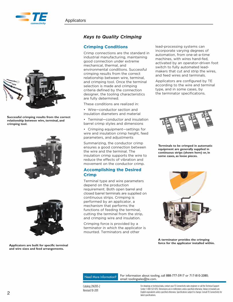
Crimping ConditionsCrimp connections are the standard inindustrial manufacturing, maintaininggood connection under extrememechanical, thermal, andenvironmental conditions. Successfulcrimping results from the correctrelationship between wire, terminal,and crimping tool. Once the terminalselection is made and crimpingcriteria defined by the connectiondesigner, the tooling characteristicsare fully determined.
These conditions are realized in:
• Wire—conductor section andinsulation diameters and material
• Terminal—conductor and insulationbarrel crimp styles and dimensions
• Crimping equipment—settings forwire and insulation crimp height, feedparameters, and adjustments
Summarizing, the conductor crimpensures a good connection betweenthe wire and the terminal. Theinsulation crimp supports the wire toreduce the effects of vibration andmovement on the conductor crimp.
Accomplishing the DesiredCrimpTerminal type and wire parametersdepend on the productionrequirement. Both open barrel andclosed barrel terminals are supplied oncontinuous strips. Crimping isperformed by an applicator, amechanism that performs thefunctions of feeding the terminal,cutting the terminal from the strip,and crimping wire and insulation.
Crimping force is provided by aterminator in which the applicator ismounted. Terminators and other
lead-processing systems canincorporate varying degrees ofautomation, from one-at-a-timemachines, with wires hand-fed,activated by an operator-driven footswitch to fully automated lead-makers that cut and strip the wires,and feed wires and terminals.
Applicators are configured by TEaccording to the wire and terminaltype, and in some cases, by the terminator specifications.
Successful crimping results from the correctrelationship between wire, terminal, andcrimping tool.
Applicators are built for specific terminaland wire sizes and feed arrangements.
Terminals to be crimped in automaticequipment are generally supplied incontinuous strips (shown here) or, insome cases, as loose pieces.
A terminator provides the crimpingforce for the applicator installed within.
Keys to Quality Crimping

3
For drawings or technical data, contact your TE Connectivity sales engineer or call the Technical SupportCenter: 1-800-522-6752. Dimensions are in millimeters unless specified otherwise. Values in brackets areEnglish equivalents unless specified otherwise. Specifications subject to change. Consult TE Connectivity forlatest specifications.
Need More Information? For information about tooling, call 888-777-5917 or 717-810-2080;email: [email protected].
Applicators
Catalog 296393-2Revised 10-2011
A brief review of common wire andinsulation crimps indicates the variety of crimping requirements that can beimplemented in TE Connectivityapplicators.
F-CRIMPThe most common crimp form.Features a U-shaped open barrel,which is closed during the crimp cycle,pressing tightly together with theconductor. This form is also commonas an insulation crimp.
TAB-LOKAn asymmetrical terminal, useful whenthere is only a narrow space availablefor the terminal. Incorporates a lockingtab to support the asymmetric forceswhen it is in use.
W-CRIMPCommon with metallic closed crimpbarrels for both stranded and solidconductors.
C-CRIMPA metallic closure with plastic barrel ontop of it—provides good support forinsulation.
OVERLAP CRIMPInsulation crimp suitable for leads withthin-walled insulation.
WRAP-OVER CRIMPAn insulation crimp in which the crimpends “interlace,” completely enclosingthe insulation.
O-CRIMPUseful for processing individual seals.
F-crimp
Tab-Lok
W-crimp
C-crimp
O-crimp
Overlap Crimp
Wrap-over Crimp
Common Crimp Forms

4
For drawings or technical data, contact your TE Connectivity sales engineer or call the Technical SupportCenter: 1-800-522-6752. Dimensions are in millimeters unless specified otherwise. Values in brackets areEnglish equivalents unless specified otherwise. Specifications subject to change. Consult TE Connectivity forlatest specifications.
Need More Information? For information about tooling, call 888-777-5917 or 717-810-2080;email: [email protected].
Applicators
Catalog 296393-2Revised 10-2011
The crimp tooling—the actual crimperand anvil that are in contact with thewire and insulation—is one of themost important factors in meetingcrimp quality specifications. TEConnectivity quality tooling is proventhrough years of experience toachieve superior performance. Fouraspects of the crimp tooling have themaximum impact.
1. Geometry and AssociatedTolerances
Terminals are designed to perform tospecification only when the finalcrimp form is within a narrow rangeof dimensions. Controlling criticalcrimp dimensions is influenced bymany factors including:
• Wire size and material variation
• Terminal size and material variation
• Equipment condition
The final quality and consistency of acrimp can never be any better thanthe quality and consistency of thetooling that is used. If other variationscould be eliminated, tooling can andshould be able to produce crimpforms that are well within specifiedtolerances. Also, variation from onetooling set to another should be heldto a minimum. Crimp tooling featuresthat are well controlled and exhibitexcellent consistency from tooling setto tooling set can result in shortersetup time as well as more consistentproduction results.
2. MaterialThe wire crimper and the anvil havedifferent functional demands. Bothhave the need to withstand high loadsand moderate shock. However, thewire crimper is in fact an aggressiveforming tool. It must withstand highshear loading that is a result offrictional loads generated as theterminal barrel slides along thecrimper surfaces in the formingprocess, and then as the barrel
terminal is plastically deformed andextruded to complete thetermination. The anvil experiencessome of the same conditions but to amuch lower level of severity.
Specific material characteristicsbearing on the crimp process includethe toughness to withstand theshocks generated during crimpingand sufficient wear resistance tomaintain dimensional tolerances.
3. Surface conditionSurface condition can affect theperformance of the crimp tooling aswell as the longevity of service. Ahard, smooth surface improvesadhesive wear properties and, thus,increases service life. The otherattribute that needs to be consideredis friction.
Friction is a contributing factor indetermining the final crimp form andprocess characteristics. Low toolingfriction results in lower crimping forceand thus can influence crimp form aswell as tooling life. Consistentfrictional characteristics betweentooling sets reduces processvariation.
The connection designer selects a terminaland crimp parameters that achieve thedesired reduction in Area Index.
Proper crimper and anvil designprovide necessary clearances withoutexcessive tolerances that can lead toflash and other crimping errors.
Significant flash can be generated withexcessive anvil-to-crimper clearance, asillustrated by nominal-design condition (a)and +0.003 in over nominal condition (b).
(b)
(a)
A polished, lubricated crimper surfacereduces friction and the associatedmaterial buildup.
Crimp Tooling — A Critical Element for a High Quality Crimp

5
For drawings or technical data, contact your TE Connectivity sales engineer or call the Technical SupportCenter: 1-800-522-6752. Dimensions are in millimeters unless specified otherwise. Values in brackets areEnglish equivalents unless specified otherwise. Specifications subject to change. Consult TE Connectivity forlatest specifications.
Need More Information? For information about tooling, call 888-777-5917 or 717-810-2080;email: [email protected].
Applicators
Catalog 296393-2Revised 10-2011
4. Surface TreatmentA commonly accepted approach toimproved crimp tooling performanceand life has been to apply a surfacetreatment to the crimp area. Applyingan appropriate surface treatment to thewire crimper will have the most benefitto crimp performance and tooling life.
An example of an effective treatment ischrome plating. Chrome plating has avery low coefficient of friction, so thereis less tendency for terminal distortion.It also has greater surface hardness,reducing adhesive wear. Finally, theplating enhances resistance to adhesionand cold welding, so there is no buildupof material transferred from theterminal that can cause incorrectcrimps on subsequent operations.
Determining Crimp QualityThe connection designer, having oncespecified the wire and terminal type,also defines the crimp parameters. Thecritical characteristic is the areareduction of the wire during the crimp.A quality crimp must achieve therequired area reduction, withoutinducing conditions, such as flash, over-or under-crimp, or bending, which cancompromise the reliability of theconnection.
Beyond visual inspection, the traditionaltest is pull-out force. This is a grossmeasure of crimp quality, and may bedifficult to perform on a 100% basis in aproduction environment.
Crimp force has also been used as ameasure, but by itself does not providethe data required.
Driven by the requirements of 6-Sigma and other international qualitystandards, TE has developed crimpheight measurement testingtechnology, which providesdependable, non-destructive, evaluationof 100% of crimped terminals withoutimpact on production throughput.Crimp height measurement is a wellestablished methodology and, incombination with crimp forcemeasurement, is superior to destructivemethods, sampling methods, ortechniques that depend on crimp forcealone.
No buildup of material is visible on achromium plated crimper surface after100,000 terminations.
Material buildup on the crimper resultsin visible deformation of the outercrimp surface in this example.
Material buildup in the crimperresults in gross deformation of thecrimped terminal.
Note significant buildup of material onan unplated crimper surface after only60,000 terminations.
Crimp height canbe measured usinga micrometer withappropriatelyshaped jaws.
Crimp height can be tested with amicrometer that has been fitted withappropriately shaped jaws. Moreeffective is the TE Crimp QualityMonitor (CQM), which can beinstalled on the terminator to providereal-time, 100% measurement.
The TE Crimp Quality Monitor usessensors mounted on the terminator ramto combine crimp force and ram positionin a calculation of crimp height on a real-time basis.
Actual real-time measurement of force vs.ram position shows a good quality crimp.

6
For drawings or technical data, contact your TE Connectivity sales engineer or call the Technical SupportCenter: 1-800-522-6752. Dimensions are in millimeters unless specified otherwise. Values in brackets areEnglish equivalents unless specified otherwise. Specifications subject to change. Consult TE Connectivity forlatest specifications.
Need More Information? For information about tooling, call 888-777-5917 or 717-810-2080;email: [email protected].
Applicators
Catalog 296393-2Revised 10-2011
End-Feed or Side-Feed —A Terminal-Driven DecisionFeed Determined by the Terminal Supply.The two main classes of terminal feed areside feed and end feed. Thisdetermination depends on the terminalgeometry, stamping process, and otherfactors in the terminal manufacture. Inboth cases, the terminals are supplied ina continuous strip, coiled on a reel.
For side feed, where the terminals move(typically) into the applicator from theoperator’s left to right, the terminals areformed attached to a carrier strip thatincludes feed holes spaced with the samepitch as the terminals on the strip. Theaxis of the terminals, i.e., the directionthat the wires are inserted for crimping, isperpendicular to the feed direction, sothe terminals are parallel on the strip. Aspart of the crimp process, the terminal iscut free from the strip, which isdiscarded.
For end feed, the terminals enter theapplicator from the rear and movetoward the operator, barrel end first. Inthis case, the terminals are aligned withthe direction of motion, and have blankmetal between the front edge of one (thecrimp end) and the rear edge (thetrailing, terminal end) of the next. Thereis no separate carrier. As part of thecrimping process, this small blank pieceof metal, or “slug,” is cut out anddiscarded.
Pre-Feed or Post-FeedIn post-feed applicators, the terminal ispositioned for crimping after the operatoractivates the switch. In pre-feedapplicators, the terminal is positioned priorto crimping. This is particularly useful forclosed barrel terminals, so that the operatorcan more easily insert the wire end.
In the side feed applicator, the applicatorfeed strip moves perpendicular to the axisof the individual terminals, from side toside with respect to the operator.
Side feedterminals (a) aremade on a singleor double carrierstrip. End feedterminals (b) areoften suppliedwhen the designwould use toomuch metal orhave too great apitch if made asside feed.
End feed terminals move from the back ofthe applicator toward the operator, barrelfirst for manual wire insertion.
(a)
(b)
Quality Applicators — Making the Right Choice

7
For drawings or technical data, contact your TE Connectivity sales engineer or call the Technical SupportCenter: 1-800-522-6752. Dimensions are in millimeters unless specified otherwise. Values in brackets areEnglish equivalents unless specified otherwise. Specifications subject to change. Consult TE Connectivity forlatest specifications.
Need More Information? For information about tooling, call 888-777-5917 or 717-810-2080;email: [email protected].
Applicators
Catalog 296393-2Revised 10-2011
Choosing an Applicator
Ocean Applicator SeriesWith the knowledge and experience of over a half century designing and manufacturing world leadingapplicators and tooling, TE Connectivity is taking terminal crimping to a new level. Using the time proven HDMand HDI applicator platforms as a base and the innovation and improvements from the System III Applicator, TEis taking a large step forward. TE has listened to customer input and market demands to innovate and improvethe combined strength of these industry leading designs to create the new Ocean Applicator.
The lead and harness industry of today is more price and quality competitive than ever before. Crimpingstandards continue to be raised to higher levels of quality and repeatability. The industry continues to expectmore from application tooling. The new Ocean Applicator Series was designed specifically to exceed therequirements of today and meet the demands of tomorrow.
By consolidating our applicator offering to this new Ocean Applicator, TE can provide design consistency andtooling standardization to the market. One of the major benefits to the customer is offering the ultimateflexibility with a choice of feeding options: New and improved Mechanical and Pneumatic feeds combined withthe innovative and precise Servo Feed option. The Ocean Series design makes it possible for customers toperform field upgrades to System III technology. It will provide an upgrade path for terminal intelligence thatallows the machine to obtain set-up features as the applicator is upgraded. Request Catalog 4-1773460-5 formore information about the Ocean Applicator Series or view it online at tooling.te.com/applicator.asp
One Applicator Platform — Modular Family Design
• 2 ram interface styles (“Atlantic” or “Pacific” style ram collar)
• Same wire crimper, insulation crimper, and anvil used on both applicator styles
• 3 feed options — • Mechanical • Pneumatic • Servo
• Same feed units can be used on Side-Feed and End-Feed style applicators. All units can be easily removed and interchanged for upgrades if desired.
Atlantic-Style SF Servo Atlantic-Style SF Pneumatic Atlantic-Style SF Mechanical
Pacific-Style SF Servo Pacific-Style SF Pneumatic Pacific-Style SF Mechanical

8
For drawings or technical data, contact your TE Connectivity sales engineer or call the Technical SupportCenter: 1-800-522-6752. Dimensions are in millimeters unless specified otherwise. Values in brackets areEnglish equivalents unless specified otherwise. Specifications subject to change. Consult TE Connectivity forlatest specifications.
Need More Information? For information about tooling, call 888-777-5917 or 717-810-2080;email: [email protected].
Applicators
Catalog 296393-2Revised 10-2011
* Non-Crimp Height Adjust Applicator is designed to run in a terminator with System III Crimp Height Adjust Technology.
Part Number System Feed Type Description Part NumberMechanical Fine Crimp Height Adjust 2151054-1
Pneumatic Fine Crimp Height Adjust 2151054-2
Atlantic Style Servo Fine Crimp Height Adjust 2151054-5
Servo Non-Crimp Height Adjust* 2151054-6
No Feed Fine Crimp Height Adjust 2151054-7
Spare Parts Kit 7-2151054-7
Feed Type Description Part NumberMechanical Fine Crimp Height Adjust 2-2151054-1
Pacific Style Pneumatic Fine Crimp Height Adjust 2-2151054-2
Servo Fine Crimp Height Adjust 2-2151054-5
No Feed Fine Crimp Height Adjust 2-2151054-7
Spare Parts Kit 7-2151054-8
Standard Features on all Ocean ApplicatorsOne of the major design goals of the Ocean Applicator Series was increased flexibility. By giving the applicatorthe ability to flex between different terminator configurations it allows customers to quickly adapt theirapplicators to whatever configuration is needed. All parts to reconfigure the applicator are included andattachable to the unit for safe storage and quick access.
As standard equipment the new applicator will have all the accessories needed to switch between 30 and40mm stroke terminators, pre-feed and post-feed cam configurations and cut and no-cut carrier options. Thewire stop / wire stripper can also be easily adjusted for the desired applications, and a mechanical counter isincluded for tracking cycle counts. The applicator comes with all parts needed to configure it to anyterminating method that is acceptable to the application.
Standard Features • Pre-feed and post-feed cams• Cut and no-cut carrier options• Adjustable terminal stripper• Adjustable spring-loaded terminal hold down• Mechanical counter• Fine adjust crimp height mechanisms
Ocean Applicator Part Number SystemBecause so many features have been added to the new applicator the part numbering system used to identifythe applicators can be simplified significantly. Now, when ordering a new applicator the customer will onlyneed to identify what style and feed type they require.

9
For drawings or technical data, contact your TE Connectivity sales engineer or call the Technical SupportCenter: 1-800-522-6752. Dimensions are in millimeters unless specified otherwise. Values in brackets areEnglish equivalents unless specified otherwise. Specifications subject to change. Consult TE Connectivity forlatest specifications.
Need More Information? For information about tooling, call 888-777-5917 or 717-810-2080;email: [email protected].
Applicators
Catalog 296393-2Revised 10-2011
Crimpmatic 970 and 971MachinesThe CRIMPMATIC 970 can processloose or reeled terminals for wires upto 16mm2 [51/2 AWG]. Working witheven larger size wires? TheCRIMPMATIC 971 can handle all theway up to 50mm2 [0 AWG]. Butautomating the crimping process isn'tthe only benefit. Crimping is faster andmore reliable. So your crimping processwill be safer and more productive, withhigher-quality finished products.
Both CRIMPMATIC models come in aspace-saving design, have an inchingmode for setup, include a reel holderfor spooled terminals, and allow two-handed operation for the application ofloose piece terminals. You can evenorder the following options:
• Crimp force monitoring
• Fine adjustment of lower dead center
• Paper spooler
Pneumatic Large Wire Applicators (for Strip Form Terminals)
• Dedicated to Crimpmatic 970 / 971
• Wire Range: up to 40, 0mm2
• Fine Adjustment
• Press Stroke: 44,0mm
• Shut Height: 158,0mm
• Applicator Feed: up to 50,0mm (pre-feed/post-feed)
Pneumatic Mid-Size Wire Applicators (for Strip Form Terminals)
• For terminators with standard AMP-style base plate (4 to 8 tons) and Crimpmatic 970 with base platefor conventional applicators.
• Wire Range: : up to 25,0 mm2 (maximum)
• Fine Adjustment
• Press Stroke: 40,0mm
• Shut Height: 135,8mm
• Applicator Base Plate: Conventional Base Plate (TE-style)
• Applicator Feed: up to 50,0mm (pre-feed/post-feed)
Loose Piece Large Wire Applicators
• Dedicated for Crimpmatic 970 / 971
• Wire Range: up to 40,0mm2
• Fine Adjustment
• Press Stroke: 44,0mm
• Shut Height: 158,0mm
• Moveable table with dedicated terminal seat (accordingto terminal geometry) to load and unload terminals
• Stroke: 40 to 50mm
• Custom designs available for nearly any terminal
Note: All loose piece applicators have a micro switch installed atthe end of the moveable table stroke. This allows it to beconnected in the terminator electrical system forpreventive safety.
Pneumatic Large Wire Applicator
Pneumatic Mid-Size Wire Applicator
Loose Piece Large Wire Applicators
Crimpmatic 971
Crimpmatic 970
10
For drawings or technical data, contact your TE Connectivity sales engineer or call the Technical SupportCenter: 1-800-522-6752. Dimensions are in millimeters unless specified otherwise. Values in brackets areEnglish equivalents unless specified otherwise. Specifications subject to change. Consult TE Connectivity forlatest specifications.
Need More Information? For information about tooling, call 888-777-5917 or 717-810-2080;email: [email protected].
Applicators
Catalog 296393-2Revised 10-2011
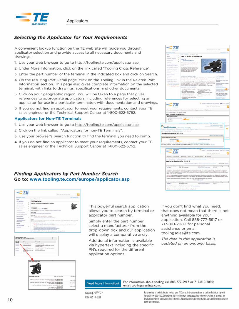
A convenient lookup function on the TE web site will guide you throughapplicator selection and provide access to all necessary documents anddrawings.
1. Use your web browser to go to http://tooling.te.com/applicator.asp.
2. Under More Information, click on the link called “Tooling Cross Reference”.
3. Enter the part number of the terminal in the indicated box and click on Search.
4. On the resulting Part Detail page, click on the Tooling link in the Related PartInformation section. This page also gives complete information on the selectedterminal, with links to drawings, specifications, and other documents.
5. Click on your geographic region. You will be taken to a page that givesreferences to appropriate applicators, including references for selecting anapplicator for use in a particular terminator, with documentation and drawings.
6. If you do not find an applicator to meet your requirements, contact your TEsales engineer or the Technical Support Center at 1-800-522-6752.
Applicators for Non-TE Terminals1. Use your web browser to go to http://tooling.te.com/applicator.asp.
2. Click on the link called :”Applicators for non-TE Terminals”.
3. Use your browser’s Search function to find the terminal you need to crimp.
4. If you do not find an applicator to meet your requirements, contact your TEsales engineer or the Technical Support Center at 1-800-522-6752.
Selecting the Applicator for Your Requirements
Finding Applicators by Part Number SearchGo to: www.tooling.te.com/europe/applicator.asp
This powerful search applicationallows you to search by terminal orapplicator part number.
Simply enter the part number,select a manufacturer from thedrop-down box and our applicationwill display a comparative array.
Additional information is availablevia hypertext including the specificPN’s required for the differentapplication options.
If you don’t find what you need,that does not mean that there is notanything available for yourapplication. Call 888-777-5917 or 717-810-2080 for personalassistance or email:[email protected].
The data in this application isupdated on an ongoing basis.
Terminal Manufacturer:
Manufacturer’s Part Number:
(include additional info)
Terminal to be inserted into housing? ❏ Yes, Part # ❏ No
Seal or grommet to be applied? ❏ Yes, Part ❏ No
Carrier Strip Type:❏ End-to-End ❏ Front
❏ Rear ❏ Front and Rear
❏ Center ❏ Loose Piece
(Large Wire)
❏ Other (Specify & attach terminal drawing)
Wire Gauge(s):
Wire Crimp Height(s):
Insulation Crimp Height(s)
Insulation Outside Diameter(s):
Pull Test (Minimum):
Wire Quantity Crimped Simultaneously: ❏ Single ❏ Multiple
Cross Section Analysis: ❏ No ❏ Yes (if yes, order 1424359-1)
Splice Application? ❏ No ❏ Yes If Yes, ❏ Pigtail or ❏ Thru Splice
Company Name
Customer Contact Title
Address
City State ZIP Code Country
Phone Number Fax Number
TE Connectivity Customer Acct Number E-Mail Address
Crimp Specification Information:
Indicate crimp specification dimensions and tolerances:
Open Barrel
Wire Crimp:
❏ “F” Type
❏ “O” Type
Insulation Crimp:
❏ “F” Type
❏ “O” Type
❏ “OV” Type
Reel Feed Direction (with operator facing front of machine):
❏ Rear (End-to-End) ❏ Left-to-Right
Note: Please list and document any special crimp, cut-off, bend, housing
requirements, or special qualification requirements.
W
W
= ±
= ±
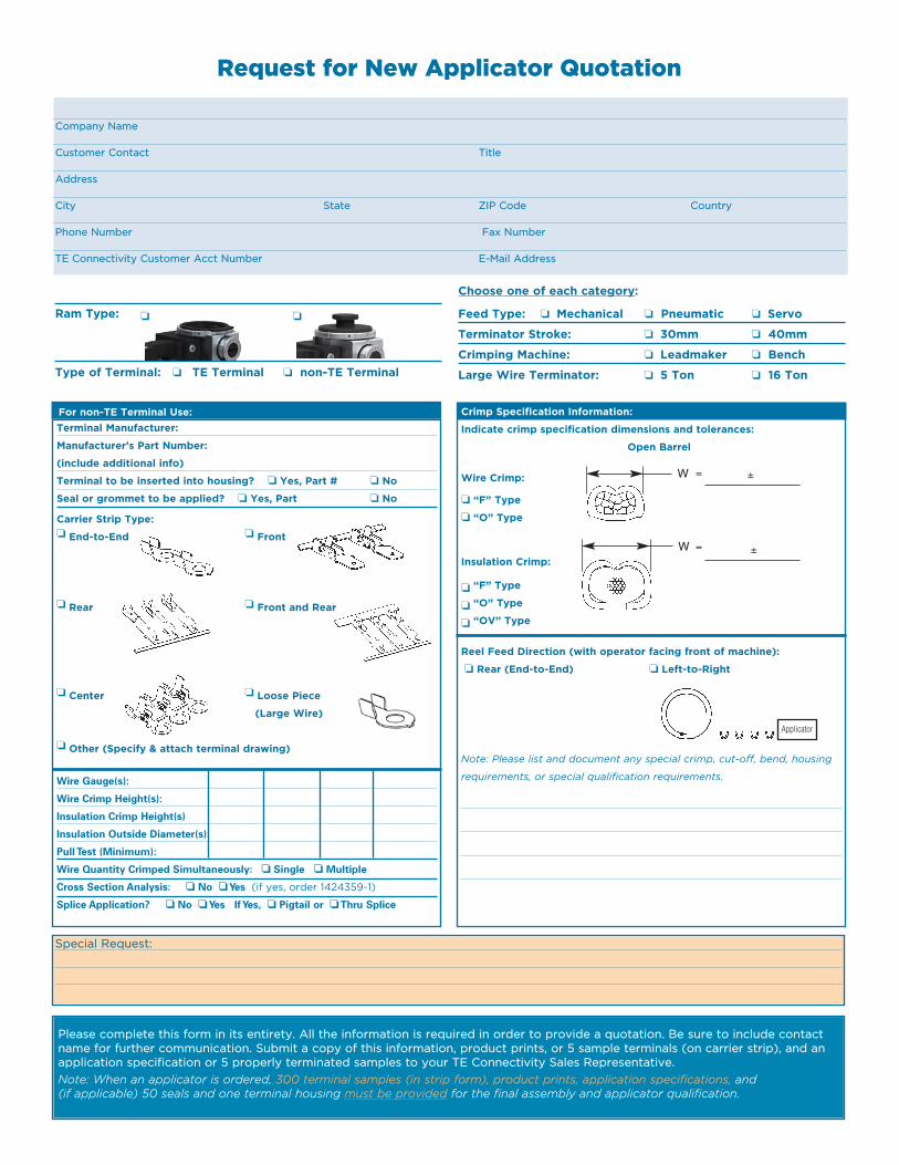
Request for New Applicator Quotation
Ram Type:
Type of Terminal: ❏ TE Terminal ❏ non-TE Terminal
Choose one of each category:
Feed Type: ❏ Mechanical ❏ Pneumatic ❏ Servo
Terminator Stroke: ❏ 30mm ❏ 40mm
Crimping Machine: ❏ Leadmaker ❏ Bench
Large Wire Terminator: ❏ 5 Ton ❏ 16 Ton
❏ ❏
For non-TE Terminal Use:
Special Request:
Please complete this form in its entirety. All the information is required in order to provide a quotation. Be sure to include contactname for further communication. Submit a copy of this information, product prints, or 5 sample terminals (on carrier strip), and anapplication specification or 5 properly terminated samples to your TE Connectivity Sales Representative.Note: When an applicator is ordered, 300 terminal samples (in strip form), product prints, application specifications, and (if applicable) 50 seals and one terminal housing must be provided for the final assembly and applicator qualification.
Applicator

12
For drawings or technical data, contact your TE Connectivity sales engineer or call the Technical SupportCenter: 1-800-522-6752. Dimensions are in millimeters unless specified otherwise. Values in brackets areEnglish equivalents unless specified otherwise. Specifications subject to change. Consult TE Connectivity forlatest specifications.
Need More Information? For information about tooling, call 888-777-5917 or 717-810-2080;email: [email protected].
Applicators
Catalog 296393-2Revised 10-2011
Crimp Quality Monitor II
Basic Analysis Monitoring
Crimp Height Entry
Production Crimp Height
FFT
Simply put, crimp height measurement is the bestnon-destructive way to ensure meeting thestringent mechanical and electrical properties ofthe crimp. New easy to use, intuitive menus alongwith enhanced monitoring and graphing lead theimproved feature set of the CQM II. Anothermajor enhancement is the ability to use CQM IIon non-TE terminators.
Versatile: On-screen programmability allows quick, flexible job set-up.Enhanced ability to support the use of USB peripherals such as: flash drives fordatabase backup, saving reports, and updating firmware. It also includes a fulllibrary of USB printers for easy printing of the many graph and report options.
Precise: Crimp height measurements are repeatable to within 0.12mm(0.0005”) for every crimp analyzed. CQM II is the only crimp monitoringsystem that offers continuous Crimp Height analysis for every crimp produced.Five different analysis methods monitor the process to the fullest extent. Thisensures quality crimps are produced and faulty crimps are detected.
Convenient: Setup is simple and fast. Only a few parameters need to be setto get the system up and running. All functions are controlled through thetouch screen, with an intuitive easy to use graphical interface. The systemwalks you through all the required steps to start production. CQM II has morechoices to observe and monitor the crimping process than ever before.
Analysis Methods The five analysis methods can be used individually or in combinationto provide the most flexible and complete coverage of the crimping process.
Crimp Height: The crimp height is the measured height of the terminals crimpbarrel formed around the wire. Crimps are analyzed to be within the settolerance zone.
Work Index: The work index is a value that is used to compare the relativeposition of a specified section of the crimp curve that occurs while the wireand terminal are compressed. Crimps are compared to historical data todetermine pass/fail. The work index is a dimensionless value.
Peak Force: The peak force is the maximum force reading that occurs duringthe crimp, minus the idle force reading. Crimps are compared to historical datato determine pass/fail. The peak force is a relative value.
Point-to-Point (P2P): A series of points are established along the crimp curvein the P2P analysis. During production each point is compared to its upper andlower control limits, and if no points are out of their limits the analysis methodconsiders the crimp to be a PASS crimp.
Fast Fourier Transform (FFT): The FFT analysis method converts the forceprofile into its component frequencies. It computes mean and standarddeviation for each of the lowest 32 frequencies from the learn crimps updatesthe mean and standard deviation with each good crimp. If 4 or morefrequencies are outside the tolerance limits, the crimp status is FAIL.Otherwise the crimp status is PASS.

13
For drawings or technical data, contact your TE Connectivity sales engineer or call the Technical SupportCenter: 1-800-522-6752. Dimensions are in millimeters unless specified otherwise. Values in brackets areEnglish equivalents unless specified otherwise. Specifications subject to change. Consult TE Connectivity forlatest specifications.
Need More Information? For information about tooling, call 888-777-5917 or 717-810-2080;email: [email protected].
Applicators
Catalog 296393-2Revised 10-2011
ServiceWhile on-site service may appear tobe the most convenient, a lessexpensive solution may be to shipyour applicator to ourApplicator/Terminator ServiceCenter. Services include:
• Warranty Services—with nocharge for labor or parts
• Calibration Services
• Equipment Repair—to applicationspecifications
• Quick Turnaround
• 90-day Warranty on Repairs
Technical Tips
Feed is CriticalMisfeeds are the most commoncause of production downtime.Over- or under-feeding can result inpremature wear of the crimper,because the terminal contacts thecrimper surface in unprotectedareas.
The applicator must be capable ofrepeatable feed distances, or bothtool life and crimp quality will becompromised.
Be certain that the feed is properlyset. Your user’s manual gives thefull procedure for feed adjustment.
The Technical Support Center can provideaccess to telephone troubleshooting, on-siteservice, or factory-level repair of applicatorsand electronic equipment.
Tooling Alignment is CrucialIncorrect tooling alignment canmean rejects due to excessive flashor terminals sticking in the crimperand being damaged or bent. It alsocan reduce tooling life, leading toout-of-specification crimping andpremature tool failure.
A simple setup procedure, usingheavy paper such as that takenfrom the terminal supply reel, canensure proper alignment of thecrimper to the anvil. This should beperformed on a periodic basis, orwhenever there are signs ofincorrect alignment.
When the crimper and anvil are not aligned,it is impossible to achieve a good crimp.
An over-fed terminal can scrape the entirecrimper surface.
Continuing Effective Crimp Performance
14
For drawings or technical data, contact your TE Connectivity sales engineer or call the Technical SupportCenter: 1-800-522-6752. Dimensions are in millimeters unless specified otherwise. Values in brackets areEnglish equivalents unless specified otherwise. Specifications subject to change. Consult TE Connectivity forlatest specifications.
Need More Information? For information about tooling, call 888-777-5917 or 717-810-2080;email: [email protected].
Applicators
Catalog 296393-2Revised 10-2011
Maintenance Keeps You inProductionIt’s easy to overlook, but routinegreasing can be a factor in reducingproduction downtime. Checkingtooling—inspecting crimpers andanvils—before they break also willsupport production continuity.
Lubrication — A Simple Step toReliable CrimpingJust as with any machinery, lubricationof the applicator reduces wear andeven protects against corrosion.
Specific use of contact lubricant onterminals prevents the friction that canlead to sticking in the crimper, bentterminals, and premature crimper wear.
Transporting Applicators SafelyAlthough they are manufactured towithstand the impact of crimping,crimpers and anvils do not fare wellwhen they contact each other. Suchcontact can scrape the plating or thecrimping surface, causing a frictionpoint. Such a friction point can formmetal buildup, ultimately causingreject crimps and even tool breakage.
This problem is easily avoided. Alwaysleave a terminal in the crimp toolingwhen moving the applicator from onelocation to another. This allows theterminal to receive any possiblecontact and protects the tooling.
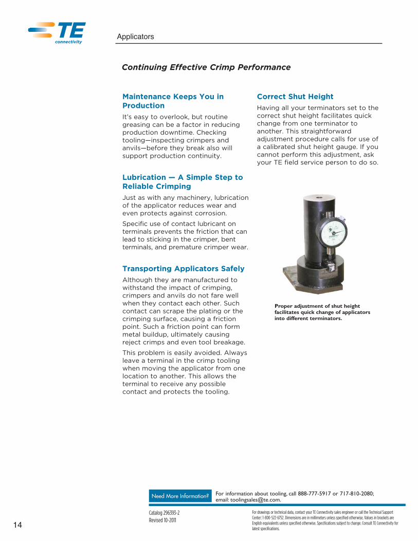
Correct Shut HeightHaving all your terminators set to thecorrect shut height facilitates quickchange from one terminator toanother. This straightforwardadjustment procedure calls for use ofa calibrated shut height gauge. If youcannot perform this adjustment, askyour TE field service person to do so.
Proper adjustment of shut heightfacilitates quick change of applicatorsinto different terminators.
Continuing Effective Crimp Performance

15
For drawings or technical data, contact your TE Connectivity sales engineer or call the Technical SupportCenter: 1-800-522-6752. Dimensions are in millimeters unless specified otherwise. Values in brackets areEnglish equivalents unless specified otherwise. Specifications subject to change. Consult TE Connectivity forlatest specifications.
Need More Information? For information about tooling, call 888-777-5917 or 717-810-2080;email: [email protected].
Applicators
Catalog 296393-2Revised 10-2011
TE Connectivity Replaceable Tooling
Only by the use of genuine TEConnectivity tooling can you beassured of the longest tool life andmost reliable production. The design,materials, and manufacturing qualityof TE tooling translate directly intofewer rejects and fewest breakdownsand interruptions.
To determine the part number fortooling for a specific applicator,simply set your web browser towww.tooling.te.com/searchparts.asp,enter the applicator part number, andclick on Search Parts. The partnumbers of replaceable tooling willbe presented.
The same lookup allows you to enterthe part number of a crimper and findout what applicators it is suitable for.
TE quality crimpers are availablefor thousands of wire andterminal requirements.
The wire crimper is configured forprecision positioning and adjustment.
Insulation crimpers follow thepositioning of the wire crimper, witha separate height adjustment disc.
A simple cross-reference lookup will help youfind the replaceable tooling for yourapplication.

Catalog 296393-2 / 10-11 / Application Tooling © 2011 Tyco Electronics Corp. AMP, AMP-O-LECTRIC, AMP-O-MATIC, TE Connectivity (logo) and TEConnectivity are trademarks. All other trademarks used are the properties of their respective owners.
Tyco Electronics Corporation, Harrisburg, PA 17105, Phone: 717-564-0100; Fax 717-986-3316
Disclaimer
While TE Connectivity has made every reasonable effort to ensure the accuracy of the information in thiscatalog, TE Connectivity does not guarantee that it is error-free, nor does TE Connectivity make anyother representation, warranty or guarantee that the information is accurate, correct, reliable or current.
TE Connectivity reserves the right to make any adjustments to the information contained herein at anytime without notice. TE Connectivity expressly disclaims all implied warranties regarding the informationcontained herein, including, but not limited to, any implied warranties of merchantability or fitness for aparticular purpose.
The dimensions in this catalog are for reference purposes only and are subject to change without notice.Specifications are subject to change without notice. Consult TE Connectivity for the latest dimensionsand design specifications.
With a long-standing tradition of quality, TEConnectivity brings you a complete solution forcrimped terminal manufacturing:
• Precision applicators for nearly any terminal choice
• Crimp Quality Monitor II— to maintain the highestquality performance and production dependability
• Highest quality replaceable crimp tooling
• Convenient web-based tools for finding the parts foryour exact requirement
• Service and support to keep your productionrunning
Put TE quality crimp tooling to work in yourproduction. Contact the Technical Support Center at 1-800-522-6752, call your TE authorized representative,or visit www.tooling.te.comfor more information.
The Right Choice for Crimped Connections