applied thermal engineering - sfu.cambahrami/pdf/2016/performance of finned tubes used in... ·...
TRANSCRIPT
Applied Thermal Engineering 106 (2016) 371–380
Contents lists available at ScienceDirect
Applied Thermal Engineering
journal homepage: www.elsevier .com/locate /apthermeng
Research Paper
Performance of finned tubes used in low-pressure capillary-assistedevaporator of adsorption cooling system
http://dx.doi.org/10.1016/j.applthermaleng.2016.06.0381359-4311/� 2016 Elsevier Ltd. All rights reserved.
⇑ Corresponding author at: School of Mechatronic Systems Engineering, SimonFraser University, # 4300, 250-13450 102nd Avenue, Surrey, BC V3T0A3, Canada.
E-mail addresses: [email protected] (P. Cheppudira Thimmaiah), [email protected](A. Sharafian), [email protected] (M. Bahrami).
Poovanna Cheppudira Thimmaiah, Amir Sharafian, Wendell Huttema, Chantal Osterman, Ameer Ismail,Aashkaran Dhillon, Majid Bahrami ⇑Laboratory for Alternative Energy Conversion (LAEC), School of Mechatronic Systems Engineering, Simon Fraser University, BC V3T 0A3, Canada
h i g h l i g h t s
� Performance of capillary-assisted evaporator in adsorption cooling systems is investigated.� External heat transfer coefficient has positive correlation to chilled water inlet temperature.� Internal heat transfer coefficient is the bottleneck of the capillary-assisted evaporator.� Up to 89% of the overall thermal resistance is due to the internal heat transfer resistance.� Tubes with higher fin density and height provide the lowest overall heat transfer resistance.
a r t i c l e i n f o
Article history:Received 22 January 2016Revised 25 May 2016Accepted 6 June 2016Available online 7 June 2016
Keywords:Capillary-assisted tubeThermal resistancesLow-operating pressure evaporatorAdsorption cooling system
a b s t r a c t
Adsorption cooling systems (ACS) are a viable alternative to vapor compression refrigeration cycles(VCRCs) where low-grade waste heat is readily available. In an ACS, which works with water as a refrig-erant, the operating pressure is quite low (�1 kPa). Under such low evaporation pressures, the height of awater column affects the water saturation pressure and, consequently, its saturation temperature, whichcan severely affect the performance of an ACS. This makes the design of evaporators of ACS different fromthose of conventional VCRCs. One practical solution in low pressure (LP) evaporators is to use capillary-assisted tubes. In this study, three enhanced tubes with different fin geometries (fin spacing and finheight), and a plain tube as a benchmark, are tested for different chilled water inlet temperatures. Theresults show that enhanced tubes have 9.8–21 times lower external convective heat transfer resistancescompared to the plain tube. In addition, the enhanced tube with the highest fin height (Turbo Chil-26 FPI)has 33% lower external convective resistance than that with lower fin height (GEWA-KS-40 FPI). Themajor finding of this study is that up to 89% of the overall thermal resistance in the enhanced tubes isdue to the internal convective resistance. This clearly indicates that the main bottleneck in the perfor-mance of a LP evaporator is the convective heat resistance inside the tube. Therefore, the internal heattransfer coefficient and internal surface area of enhance tubes should be increased to enhance the perfor-mance of the LP evaporator and overall specific cooling power (SCP) of ACS.
� 2016 Elsevier Ltd. All rights reserved.
1. Introduction
A vapor compression refrigeration cycle (VCRC) is the dominantheating, ventilation and air-conditioning (HVAC) technologyaccounting for around 38% of energy consumption in the U.S build-ing sector [1]. Vapor-compression equipment account for 99% ofspace-cooling energy consumption [2]. In transportation sector, a
VCRC in a vehicle air conditioning (A/C) system can add up to5–6 kW peak power draw [3] on an internal combustion engine(ICE). Also, in an ICE of a light-duty vehicle about 40% of the fuelenergy is wasted in the form of exhaust gas and about 30% of thefuel energy is dissipated through the engine coolant [4]. To reducevehicle fuel consumption and utilize some of this waste heat, athermally-driven ACS can replace a conventional VCRC. A portionof the waste heat of an ICE is sufficient to run the ACS andgenerates the cooling power (around 1 TR [5]) required for thevehicle A/C applications. The substitute for the compressor of aVCRC is adsorber bed(s) in which a refrigerant (adsorbate), suchas water or methanol, is adsorbed at the surface of an adsorbent,
Nomenclature
A heat transfer surface area (m2)A/C air conditioningACS adsorption cooling systemcp heat capacity at constant pressure (J/kg K)C capacity rate (W/K)DTLM log mean temperature difference (K)FPI fins per inchICE internal combustion engine_m mass flow rate (kg/s)NTU number of transfer unitsP pressure (Pa)_Q total heat transfer rate (W)_q heat transfer rate (W)r radius (m)H height of the fin (m)k thermal conductivity of the tube material (W/m K)L length of the tube (m)T temperature (�C)
Twall average wall temperatureTref average liquid refrigerant temperaturet time (s)U overall heat transfer coefficient (W/m2 K)VCRC vapor compression refrigeration cycleW gap between the two fins (m)ho external heat transfer coefficient (W/m2 K)hi internal heat transfer coefficient (W/m2 K)e effectiveness (%)
Subscriptschilled chilled waterevap evaporatori ino outmin minimum
372 P. Cheppudira Thimmaiah et al. / Applied Thermal Engineering 106 (2016) 371–380
such as zeolite, silica gel, or activated carbon. Most of these mate-rials are non-toxic, non-corrosive, and inexpensive [6], whichmakes ACS a safe and environmentally friendly technology. Amongthe existing refrigerants, water has the highest enthalpy of evapo-ration (latent heat). However, the saturation pressure of water attemperatures below 100 �C, where the evaporator of an A/C systemoperates, is below atmospheric pressure. Typically an ACS evapora-tor operates between 3 and 20 �C, and has the operating pressureranging from 0.76 to 2.34 kPa, respectively [7]. Under such operat-ing conditions, a conventional evaporator seizes to performanceefficiently and can severely reduce the performance of an ACS[8,9]. Accordingly, an ACS that uses water as the refrigerantrequires a low-operating pressure (LP) evaporator. LP evaporatoris an integral component of an ACS for achieving higher specificcooling power (SCP) [10]. A LP evaporator can be a flooded type,where liquid water (refrigerant) covers the evaporator tubes andboiling occurs due to natural convection [11,12] for a typical wallsuperheat temperature of 5 K.
Accumulation of liquid water in a flooded-type LP evaporatorcreates a water column, which results in a hydrostatic pressure dif-ference between the liquid water-vapor interface and the bottomof the water column. This hydrostatic pressure changes the satura-tion temperature and pressure of the water. As a result, the coolingpower generation of an ACS drastically reduces. To have a uniformwater saturation temperature, the static pressure of the water inthe LP evaporator should be minimized. Two practical solutionsto resolve this issue are: (i) falling film evaporation, and (ii)capillary-assisted evaporation. Florides et al. [13] developed a fall-ing film evaporator operating at 0.9 kPa for an absorption machinein which the refrigerant was showered on vertical tubes. Castroet al. [14] also used falling film evaporator technology at an oper-ating pressure of 1.0 kPa for an absorption machine but the refrig-erant was sprayed on horizontal tubes. Falling film evaporatorssucceed in avoiding the influence of the liquid column on theevaporation and provide high heat transfer coefficient [15–18]specifically for large cooling capacities in a low footprint. However,uniform distribution of refrigerant on horizontal tubes, parasiticpower consumption (by internal pumps and circulators), and liquidspray equipment make the falling film evaporators impractical foran ACS installed in a light-duty vehicle A/C system.
Low-operating pressure capillary-assisted evaporation for ACSapplications is a relatively novel concept and there are only afew studies available in the literature. Sabir et al. [19–21] studied
the capillary-assisted evaporation on the inner surface of the tubefor a vapor absorption chiller and achieved a maximum coolingpower of 0.7 kW. The evaporator used air as the heat transfer fluidand due to high pressure drop, the refrigerant had to overcome theflow resistance before reaching the absorber. Capillary-assistedflow and evaporation inside circumferential rectangular micro-grooves were studied by Xia et al. [22,23]. They immersed a finnedtube with outside circumferential micro-grooves into a pool of liq-uid to investigate the effects of immersion depth, evaporationpressure, and superheating degree on the performance of the evap-orator. Their experimental results showed that the evaporationheat transfer coefficient has a positive correlation with the evapo-ration pressure, and a negative correlation with the superheatingand immersion depth. Wang et al. [24] developed an evaporatorfor a silica gel-water ACS based on the work shown in Refs.[22,23]. They claimed that the evaporation heat transfer coefficientwas about 5000W/(m2 K). Lanzerath et al. [25,26] studied a com-bination of finned tubes and thermal coating for capillary-assisted evaporation at low pressures. Their investigation showeda strong dependency of the total heat transfer coefficienton the water filling level. Their study also established that thecombination of macroscopic fin structures and micro porouscoatings yielded an evaporation heat transfer coefficient of5500W/(m2 K), which is 11 times higher than that of a plain tubewith the same outer diameter [6]. Sabir and Bwalya [20] observedthat internally powder coated evaporator resulted in much betterperformance and overall heat transfer coefficient when comparedto internally open groove evaporators with deep and shallowgrooves. Schnabel et al. [7] evaluated different evaporator conceptsfor adsorption systems, and capillary-assisted evaporation was oneamong them. They achieved a maximum cooling power of 1.2 kWwhile maintaining the operating pressure between 1.1 and 1.7 kPa.The tubes in their study involved both outer and inner structuresbut Schnabel et al. did not clearly distinguish the effect of innerand outer heat transfer.
The aforementioned studies focused only on enhancing the heattransfer from the external surface of the tubes and they did notreport the importance of the effects of thermal resistances to theheat transfer. Therefore, this study attempts to fill this gap in theliterature. To generate cooling, the heat has to be transferred fromthe chilled liquid water flowing inside the tube to the tube wall,and finally, to the refrigerant. The main goals of this researchare to evaluate the thermal resistances to the heat flow, such as

Fig. 2. Schematic of capillary-assisted evaporation. The red dots indicate thepositions of thermocouples. (For interpretation of the references to color in thisfigure legend, the reader is referred to the web version of this article.)
P. Cheppudira Thimmaiah et al. / Applied Thermal Engineering 106 (2016) 371–380 373
external heat transfer resistance, 1/(hoAo), and the overall heattransfer resistance, 1/(UA), in LP evaporators. Enhancements dueto continuous parallel fins on the external surface of the tubeincrease the tube wall conductive resistance. Finally, the internalheat transfer resistance, 1/(hiAi), should be determined. The impor-tance of the thermal resistances has never been assessed before forLP capillary-assisted evaporation in ACS applications.
In this study, three enhanced tubes with different fin height andfin spacing, and a plain tube, as benchmark, are tested underdifferent operating conditions. In addition, a parametric study isconducted on the selected tube under different chilled water inlettemperatures. The dependence of the external heat transfer coeffi-cient (ho) under varying liquid water level is presented in thispaper. The estimation of thermal resistances of three tested com-mercially available tubes (Turbo Chil- 26 FPI, Turbo Chil-40 FPIand GEWA-KS-40 FPI) in the application of LP capillary-assistedevaporators are one of the novel contributions of this research.
2. Capillary-assisted evaporation
Due to surface tension inside a rectangular-groove, the liquid–vapor interface forms a curved surface, which leads to a pressurejump across the interface. This pressure jump can be calculatedby the augmented Young–Laplace equation [27]. The curvatureincreases gradually along the circumferential direction of thegroove, creating a pressure gradient due to meniscus deformation[27], which is responsible for the upward flow of the liquid. Asschematically shown in Fig. 1, the extended meniscus region canbe divided into three sub-regions (I) the non-evaporating region,(II) the evaporating thin film region, and (III) the bulk region. Themost heat is transferred in region II, where the liquid film is extre-mely thin and the thermal resistance is extremely low. As the heatflux imposed on the thin film region increases, the evaporation andheat transfer rates through the evaporating thin film also increase[28]. More information on the mechanisms of heat transfer in cap-illary assisted grooved tubes can be found elsewhere [22,27,29–31].
3. Experimental details
A schematic of capillary-assisted evaporation is shown in Fig. 2,where an enhanced tube with external fins and small fin spacing isin contact with a pool of liquid. Due to capillary action, the liquidcovers the outside surface of the tube. Chilled liquid water pro-vided by a temperature control system (TCS) is circulated insidethe tube and heat is transferred to the thin liquid film on the out-side of the tube, leading to evaporation.
A capillary-assisted LP evaporator built in the Laboratory forAlternative Energy Conversion (LAEC) is shown in Fig. 3. The evap-orator tube consisted of a four-pass arrangement with a totallength of 1.54 m. Capillary evaporation takes place at the free sur-face of the tube helping to maintain the evaporation heat transfer
Fig. 1. Evaporating meniscus inside a rectangular-groove.
rate as the water level decrease. The tube was placed horizontallyat the bottom of the box to minimize the water height as shown inFig. 3b. Type T thermocouples (Omega, model #5SRTC-TT-T-36-36)with accuracy of 0.75% of the reading in �C, and a pressure trans-ducer with 0.13–3330 kPa operating range (MKS Baratron� Capac-itance Manometer, Type 722B) and accuracy of 0.5% of the readingwere used to record the temperature and pressure variations at thelocations shown in Fig. 3. A positive displacement flowmeter (FLO-MEC, Model #OM015S001-222) with the accuracy of 0.5% of read-ing was employed to measure the mass flow rate of the chilledwater. The thermocouples used to measure the outside wall tem-perature of the tubes were placed at 90� apart at two differentcross sections as shown in Figs. 2 and 3.
A schematic diagram of the experimental setup is shown inFig. 4. The experimental test bed was designed to measure theexternal heat transfer coefficient (ho) and the overall heat transfercoefficient (U) of the evaporator. The setup consisted of a TCS and avariable speed pump to provide a constant temperature chilledwater to the evaporator at different mass flow rates. A controlvalve was used to regulate the pressure inside the evaporator. A
Fig. 3. Capillary-assisted evaporator built for testing different enhanced tubes: (a)top view, and (b) side view. Red dots indicate the location of thermocouples. (Forinterpretation of the references to color in this figure legend, the reader is referredto the web version of this article.)

Table 1Operating conditions for the experiments.
Parameter Values
Chilled water inlettemperatures
10 �C 15 �C 20 �C
Chilled water flow rate 2.3–2.5 kg/min 2.3–2.5 kg/min 2.3–2.5 kg/minEvaporator pressure 0.8 kPa 1.1 kPa 1.5 kPaAmount of water in the
evaporatorat start of experiment
1200 g 1200 g 1200 g
(a)
(b)
TCS
P
T T
F
Evaporator
T
Makeup water
Control valve
Cold trap
Vacuum pump
Evaporator
Chilled water inlet
Chilled water outlet
Makeup water
Flow meter
Variable speed pump
Cold traps
To vacuum pump
Fig. 4. (a) Schematic of the experimental setup and (b) its photograph.
374 P. Cheppudira Thimmaiah et al. / Applied Thermal Engineering 106 (2016) 371–380
vacuum pump and cold trap were used to mimic an adsorber bedof an ACS. The cold trap, filled with a dry ice and isopropyl alcoholsolution, was used to protect the vacuum pump from the watervapor coming from the evaporator. The operating conditions dur-ing the experiments are summarized in Table 1. Once the evapora-tor was evacuated using the vacuum pump, the evaporator wasfilled with water (1200 g) to immerse the evaporator tube in water.When all the temperatures and pressure inside the evaporatorbecame constant, the control valve was opened and adjusted untilthe evaporator pressure reached a specific value listed in Table 1.No water was added during the course of the experiment, so thewater level dropped until all of the water in the chamber evapo-rated. The tests were conducted for three types of commerciallyavailable enhanced tubes with different fin structures and oneplain tube, as a benchmark, as listed in Table 2.
3.1. Data analysis
The operating conditions were kept constant and monitoreduntil a steady-state condition was reached. The chilled water inletand outlet temperatures, Tchilled,i and Tchilled,o, and the mass flowrate were used to calculate the heat flow rate [32]:
_qevapðWÞ ¼ _mchilledcp;chilled Tchilled;i � Tchilled;o� � ð1Þ
The total evaporation rate, _Q evap, is calculated by time averaging theheat flow rate given in Eq. (1):
_QevapðWÞ ¼R t2t1
_qevapdt
t2 � t1ð2Þ
where t1 and t2 are the beginning and end of the time when thetemperatures in the evaporator remain constant. Finally, the overallevaporator heat transfer conductance, UA, is given by:
UA ¼_Qevap
DTLM; evapð3Þ
where A is the nominal surface area of the tubes and DTLM;evap is thelogarithmic mean temperature difference between the chilled waterand the refrigerant:
DTLM;evap ¼ Tchilled;i � Tchilled;o
ln Tchilled;i�TliqTchilled;o�T liq
� � ð4Þ
where Tliq is the average of Tliq,1 and Tliq,2, as shown in Fig. 3a. Eq. (5)gives the external heat transfer coefficient (ho):
ho ¼_Q evap
AoðDTÞ ð5Þ
where DT is the difference between tube wall temperature,Twall, and liquid refrigerant temperature, T liq:
Twall ¼ 18
X8i¼1
T i ð6Þ
T liq ¼ 12
T liq;1 þ T liq;2� � ð7Þ
Finally, the internal heat transfer coefficient (hi) of enhanced tubesis deduced using Eq. (8) [33]:
1UA
¼ 1hoAo
þ 1hiAi
þ Ro;finned tube
� �ð8Þ
The first term on the right hand side of Eq. (8) describes the externalconvective heat resistance due to evaporation on the external sur-face of the tube, the second term is the internal convective heatresistance due to single-phase flow inside the tube, and the thirdterm is the conductive heat resistance of the tube wall. Fromthe analysis shown in Appendix A, the internal convective heatresistance is calculated. The internal heat transfer coefficient (hi)of the plain tube is calculated using the following relation
1UA
¼ 1hoAo
þ 1hiAi
þ lnðro=riÞ2pkL
ð9Þ
The effectiveness (e) and number of transfer units (NTU) of the LPevaporator are calculated by Eqs. (10) and (11), respectively.
e ¼_Q evap
_Qmax
¼ _mchilled cp;chilled Tchilled; i � Tchilled; o� �
_mchilled cp;chilled Tchilled; i � T liq� � ¼ Tchilled; i � Tchilled; o
Tchilled; i � T liq
ð10Þ
NTU ¼ UA_mchilled cp;chilled
ð11Þ
4. Uncertainty analysis
The systematic uncertainty [34] in calculation of Uwas 1.1% andthe random uncertainty in the measurement of U over time was7%. Thus, the maximum uncertainty in the calculation of U was8%. The systematic uncertainty in calculation of ho was equal to1.5% and the random uncertainty in the measurement of ho over

Table 2Technical specifications of the enhanced tubes used for the experiments.
Tube name and details Fin structure 5� zoom view
Turbo Chil-26 FPI (Wolverine Tube Inc.)OD: 19.05 mm (3/400)Fin height: 1.422 mmMin. wall under fins: 0.737 mmInside surface area: 0.049 m2/mOutside surface area: 0.193 m2/m
Turbo Chil-40 FPI (Wolverine Tube Inc.)OD: 19.05 mm (3/400)Fin height: 1.473 mmMin. wall under fins: 0.635 mmInside surface area: 0.051 m2/mOutside surface area: 0.263 m2/m
GEWA-KS-40 FPI (Wieland Thermal Solutions)OD: 19.05 mm (3/400)Fin height: 0.9 mmMin. wall under fins: 0.7 mmInside surface area: 0.0489 m2/mOutside surface area: 0.194 m2/m
Plain tubeOD: 19.05 mm (3/400)Inside surface area: 0.0547 m2/mOutside surface area: 0.0598 m2/m
P. Cheppudira Thimmaiah et al. / Applied Thermal Engineering 106 (2016) 371–380 375
time was 9.0%. Therefore, the maximum uncertainty in thecalculation of ho was 10.5%. The detailed calculations of the totaluncertainties for U and ho are shown in Appendix B.
5. Results and discussion
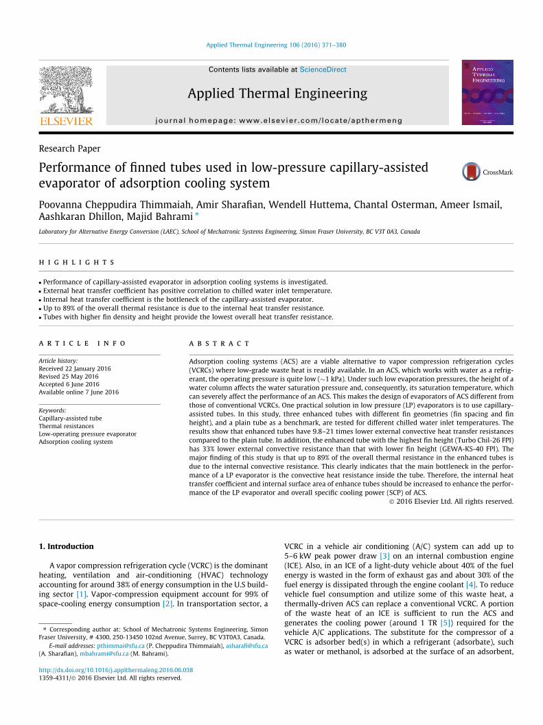
The operating pressure and temperature of the evaporator ver-sus time for a GEWA-KS-40 FPI, provided by Wieland ThermalSolution, IL, USA, tube at a constant chilled water inlet temperatureof 15 �C are shown in Fig. 5. It can be seen in Fig. 5a that the initialevaporator pressure is higher than the saturation pressure of waterat 15 �C due to dissolved gases from the makeup water. The evap-orator pressure decreases once the control valve is opened andremains constant until the evaporator runs out of water, at whichtime the pressure drops suddenly. Fig. 5b shows that all of thethermocouples have the same reading at the beginning of the test(equilibrium state). After opening the control valve, the evapora-tion temperature is set by the evaporation pressure. The locationsof the thermocouples measuring the wall temperatures are shownin Fig. 3a.
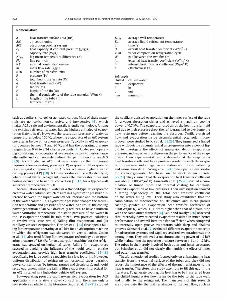
Fig. 6 shows the effect of capillary phenomenon on the perfor-mance of an evaporator built with a GEWA-KS-40 FPI tube atchilled water inlet temperature of 15 �C compared with the onebuilt with plain tubes. As shown in Fig. 6a, the GEWA-KS-40 FPItube results in an increasing ho over time. Even as the height ofthe liquid decreases, the capillary action ensures that the entireoutside surface of the tube remains covered and the external heattransfer is characterized by the thin film evaporation. As seen inFig. 2, the external surface of the tube is covered by pooled water
and capillary water. As the height of the liquid falls, the hydrostaticpressure in the pooled water column decreases. This drop in hydro-static pressure allows the saturation temperature of the liquid col-umn to drop as well. Fig. 6a also suggests that the effect of liquidlevel is an important parameter to achieve higher external heattransfer coefficient from capillary-assisted evaporators. Fig. 6bshows that the plain tube fails to maintain the external heat trans-fer rate and, consequently, ho drops as the height of the liquidwater inside the evaporator drops. As the level of the liquid waterdrops and since there is no capillary action, the evaporation ismainly due to pool boiling. Even if there is a decrease in hydro-static pressure as the level drops, the heat transfer surface areaavailable for the pool boiling is also decreased.
The variation of external heat transfer coefficient (ho) and over-all heat transfer coefficient (U) against the chilled water tempera-ture are shown in Fig. 7. As shown in Fig. 7a, increasing the chilledwater inlet temperature results in higher evaporation temperature.A higher evaporation temperature increases the thermal conduc-tivity and decreases the viscosity of the liquid film around the tube,thereby increasing ho. The results shown in Fig. 7a indicate positivecorrelation between ho and chilled water inlet temperature. Whenthe chilled water inlet temperature is increased from 10 to 20 �C, hovaries from 2800 to 5030W/m2 K for Turbo Chil-40 FPI tube. Asshown in Fig. 7a, the enhanced tubes result in an average hoincrease of 3.9, 4.2, and 3.9 times compared to the plain tube atchilled water inlet temperatures of 10, 15, and 20 �C, respectively.The Turbo Chil-40 FPI tube provides the highest ho of 5030W/m2 Kat the chilled water inlet temperature of 20 �C, followed by TurboChil-26 FPI. The variations of overall heat transfer coefficient, U,
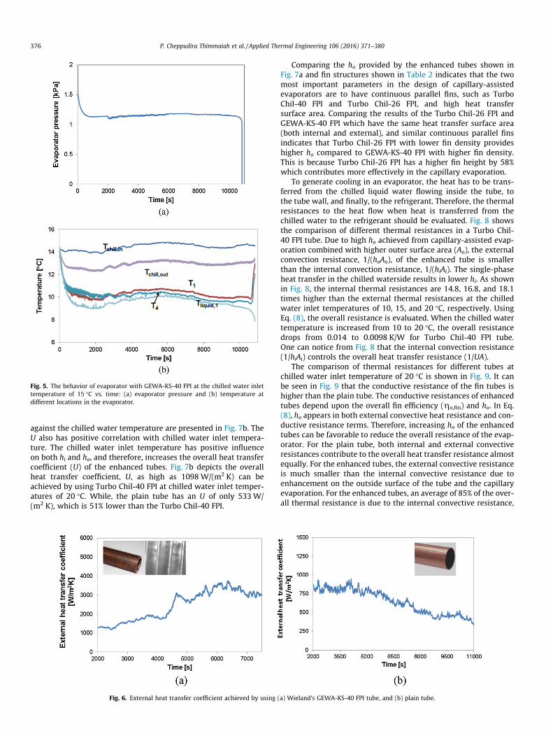
Fig. 5. The behavior of evaporator with GEWA-KS-40 FPI at the chilled water inlettemperature of 15 �C vs. time: (a) evaporator pressure and (b) temperature atdifferent locations in the evaporator.
376 P. Cheppudira Thimmaiah et al. / Applied Thermal Engineering 106 (2016) 371–380
against the chilled water temperature are presented in Fig. 7b. TheU also has positive correlation with chilled water inlet tempera-ture. The chilled water inlet temperature has positive influenceon both hi and ho, and therefore, increases the overall heat transfercoefficient (U) of the enhanced tubes. Fig. 7b depicts the overallheat transfer coefficient, U, as high as 1098W/(m2 K) can beachieved by using Turbo Chil-40 FPI at chilled water inlet temper-atures of 20 �C. While, the plain tube has an U of only 533W/(m2 K), which is 51% lower than the Turbo Chil-40 FPI.
Fig. 6. External heat transfer coefficient achieved by using (
Comparing the ho provided by the enhanced tubes shown inFig. 7a and fin structures shown in Table 2 indicates that the twomost important parameters in the design of capillary-assistedevaporators are to have continuous parallel fins, such as TurboChil-40 FPI and Turbo Chil-26 FPI, and high heat transfersurface area. Comparing the results of the Turbo Chil-26 FPI andGEWA-KS-40 FPI which have the same heat transfer surface area(both internal and external), and similar continuous parallel finsindicates that Turbo Chil-26 FPI with lower fin density provideshigher ho compared to GEWA-KS-40 FPI with higher fin density.This is because Turbo Chil-26 FPI has a higher fin height by 58%which contributes more effectively in the capillary evaporation.
To generate cooling in an evaporator, the heat has to be trans-ferred from the chilled liquid water flowing inside the tube, tothe tube wall, and finally, to the refrigerant. Therefore, the thermalresistances to the heat flow when heat is transferred from thechilled water to the refrigerant should be evaluated. Fig. 8 showsthe comparison of different thermal resistances in a Turbo Chil-40 FPI tube. Due to high ho achieved from capillary-assisted evap-oration combined with higher outer surface area (Ao), the externalconvection resistance, 1/(hoAo), of the enhanced tube is smallerthan the internal convection resistance, 1/(hiAi). The single-phaseheat transfer in the chilled waterside results in lower hi. As shownin Fig. 8, the internal thermal resistances are 14.8, 16.8, and 18.1times higher than the external thermal resistances at the chilledwater inlet temperatures of 10, 15, and 20 �C, respectively. UsingEq. (8), the overall resistance is evaluated. When the chilled watertemperature is increased from 10 to 20 �C, the overall resistancedrops from 0.014 to 0.0098 K/W for Turbo Chil-40 FPI tube.One can notice from Fig. 8 that the internal convection resistance(1/hiAi) controls the overall heat transfer resistance (1/UA).
The comparison of thermal resistances for different tubes atchilled water inlet temperature of 20 �C is shown in Fig. 9. It canbe seen in Fig. 9 that the conductive resistance of the fin tubes ishigher than the plain tube. The conductive resistances of enhancedtubes depend upon the overall fin efficiency (go,fin) and ho. In Eq.(8), ho appears in both external convective heat resistance and con-ductive resistance terms. Therefore, increasing ho of the enhancedtubes can be favorable to reduce the overall resistance of the evap-orator. For the plain tube, both internal and external convectiveresistances contribute to the overall heat transfer resistance almostequally. For the enhanced tubes, the external convective resistanceis much smaller than the internal convective resistance due toenhancement on the outside surface of the tube and the capillaryevaporation. For the enhanced tubes, an average of 85% of the over-all thermal resistance is due to the internal convective resistance,
a) Wieland’s GEWA-KS-40 FPI tube, and (b) plain tube.
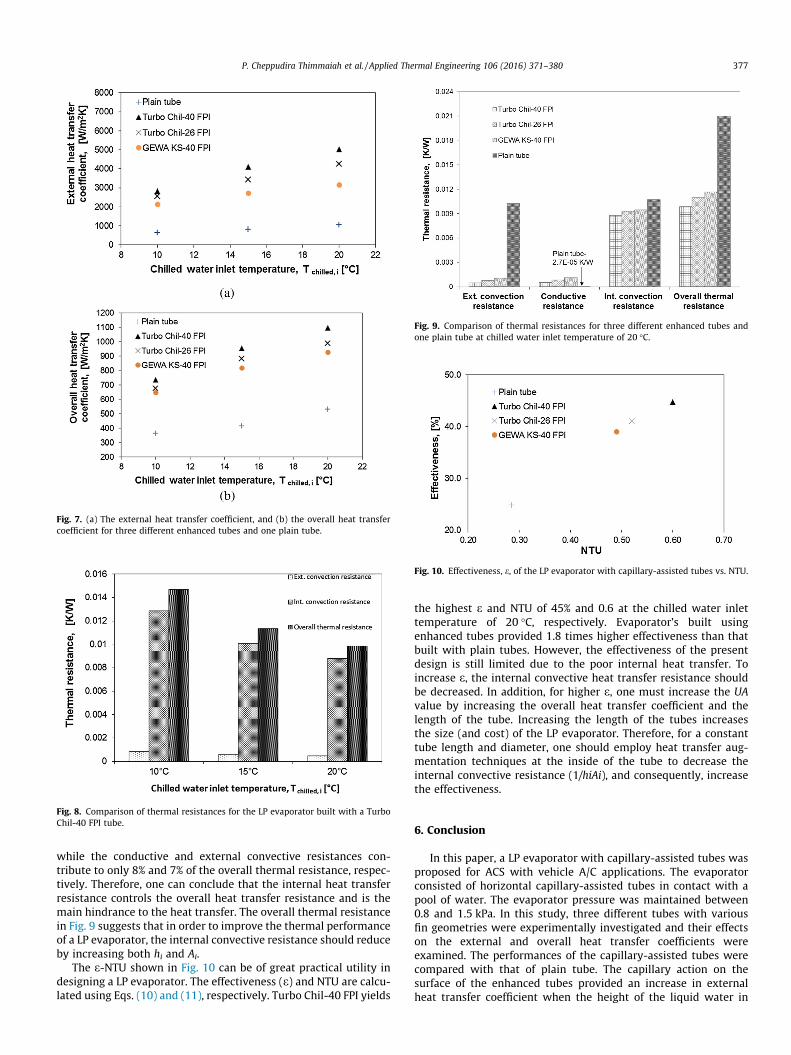
Fig. 7. (a) The external heat transfer coefficient, and (b) the overall heat transfercoefficient for three different enhanced tubes and one plain tube.
Fig. 8. Comparison of thermal resistances for the LP evaporator built with a TurboChil-40 FPI tube.
Fig. 9. Comparison of thermal resistances for three different enhanced tubes andone plain tube at chilled water inlet temperature of 20 �C.
Fig. 10. Effectiveness, e, of the LP evaporator with capillary-assisted tubes vs. NTU.
P. Cheppudira Thimmaiah et al. / Applied Thermal Engineering 106 (2016) 371–380 377
while the conductive and external convective resistances con-tribute to only 8% and 7% of the overall thermal resistance, respec-tively. Therefore, one can conclude that the internal heat transferresistance controls the overall heat transfer resistance and is themain hindrance to the heat transfer. The overall thermal resistancein Fig. 9 suggests that in order to improve the thermal performanceof a LP evaporator, the internal convective resistance should reduceby increasing both hi and Ai.
The e-NTU shown in Fig. 10 can be of great practical utility indesigning a LP evaporator. The effectiveness (e) and NTU are calcu-lated using Eqs. (10) and (11), respectively. Turbo Chil-40 FPI yields
the highest e and NTU of 45% and 0.6 at the chilled water inlettemperature of 20 �C, respectively. Evaporator’s built usingenhanced tubes provided 1.8 times higher effectiveness than thatbuilt with plain tubes. However, the effectiveness of the presentdesign is still limited due to the poor internal heat transfer. Toincrease e, the internal convective heat transfer resistance shouldbe decreased. In addition, for higher e, one must increase the UAvalue by increasing the overall heat transfer coefficient and thelength of the tube. Increasing the length of the tubes increasesthe size (and cost) of the LP evaporator. Therefore, for a constanttube length and diameter, one should employ heat transfer aug-mentation techniques at the inside of the tube to decrease theinternal convective resistance (1/hiAi), and consequently, increasethe effectiveness.
6. Conclusion
In this paper, a LP evaporator with capillary-assisted tubes wasproposed for ACS with vehicle A/C applications. The evaporatorconsisted of horizontal capillary-assisted tubes in contact with apool of water. The evaporator pressure was maintained between0.8 and 1.5 kPa. In this study, three different tubes with variousfin geometries were experimentally investigated and their effectson the external and overall heat transfer coefficients wereexamined. The performances of the capillary-assisted tubes werecompared with that of plain tube. The capillary action on thesurface of the enhanced tubes provided an increase in externalheat transfer coefficient when the height of the liquid water in
378 P. Cheppudira Thimmaiah et al. / Applied Thermal Engineering 106 (2016) 371–380
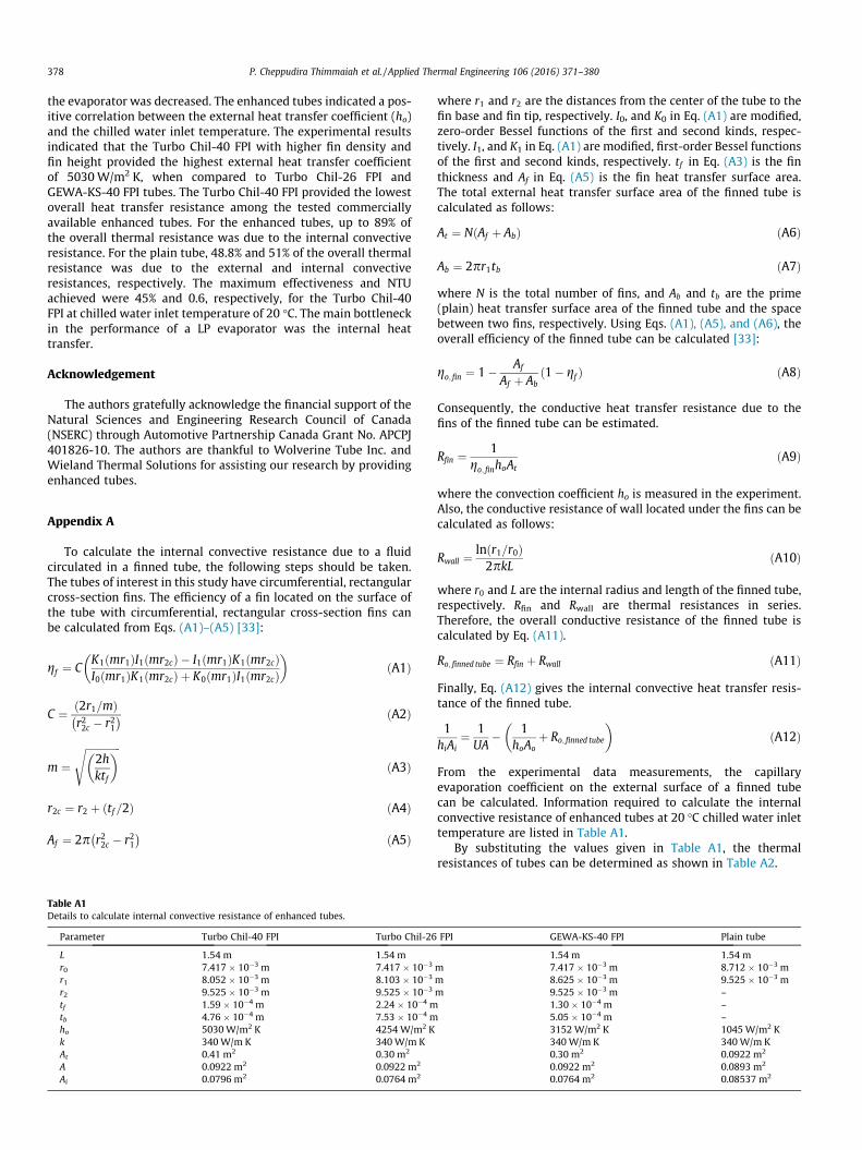
the evaporator was decreased. The enhanced tubes indicated a pos-itive correlation between the external heat transfer coefficient (ho)and the chilled water inlet temperature. The experimental resultsindicated that the Turbo Chil-40 FPI with higher fin density andfin height provided the highest external heat transfer coefficientof 5030W/m2 K, when compared to Turbo Chil-26 FPI andGEWA-KS-40 FPI tubes. The Turbo Chil-40 FPI provided the lowestoverall heat transfer resistance among the tested commerciallyavailable enhanced tubes. For the enhanced tubes, up to 89% ofthe overall thermal resistance was due to the internal convectiveresistance. For the plain tube, 48.8% and 51% of the overall thermalresistance was due to the external and internal convectiveresistances, respectively. The maximum effectiveness and NTUachieved were 45% and 0.6, respectively, for the Turbo Chil-40FPI at chilled water inlet temperature of 20 �C. The main bottleneckin the performance of a LP evaporator was the internal heattransfer.
Acknowledgement
The authors gratefully acknowledge the financial support of theNatural Sciences and Engineering Research Council of Canada(NSERC) through Automotive Partnership Canada Grant No. APCPJ401826-10. The authors are thankful to Wolverine Tube Inc. andWieland Thermal Solutions for assisting our research by providingenhanced tubes.
Appendix A
To calculate the internal convective resistance due to a fluidcirculated in a finned tube, the following steps should be taken.The tubes of interest in this study have circumferential, rectangularcross-section fins. The efficiency of a fin located on the surface ofthe tube with circumferential, rectangular cross-section fins canbe calculated from Eqs. (A1)–(A5) [33]:
gf ¼ CK1ðmr1ÞI1ðmr2cÞ � I1ðmr1ÞK1ðmr2cÞI0ðmr1ÞK1ðmr2cÞ þ K0ðmr1ÞI1ðmr2cÞ� �
ðA1Þ
C ¼ ð2r1=mÞr22c � r21� � ðA2Þ
m ¼ffiffiffiffiffiffiffiffiffiffiffiffiffiffi2hktf
� �sðA3Þ
r2c ¼ r2 þ ðtf =2Þ ðA4Þ
Af ¼ 2p r22c � r21� � ðA5Þ
Table A1Details to calculate internal convective resistance of enhanced tubes.
Parameter Turbo Chil-40 FPI Turbo Chil-26
L 1.54 m 1.54 mr0 7.417 � 10�3 m 7.417 � 10�3
r1 8.052 � 10�3 m 8.103 � 10�3
r2 9.525 � 10�3 m 9.525 � 10�3
tf 1.59 � 10�4 m 2.24 � 10�4 mtb 4.76 � 10�4 m 7.53 � 10�4 mho 5030 W/m2 K 4254 W/m2 Kk 340 W/m K 340W/m KAt 0.41 m2 0.30 m2
A 0.0922 m2 0.0922 m2
Ai 0.0796 m2 0.0764 m2
where r1 and r2 are the distances from the center of the tube to thefin base and fin tip, respectively. I0, and K0 in Eq. (A1) are modified,zero-order Bessel functions of the first and second kinds, respec-tively. I1, and K1 in Eq. (A1) are modified, first-order Bessel functionsof the first and second kinds, respectively. tf in Eq. (A3) is the finthickness and Af in Eq. (A5) is the fin heat transfer surface area.The total external heat transfer surface area of the finned tube iscalculated as follows:
At ¼ NðAf þ AbÞ ðA6Þ
Ab ¼ 2pr1tb ðA7Þ
where N is the total number of fins, and Ab and tb are the prime(plain) heat transfer surface area of the finned tube and the spacebetween two fins, respectively. Using Eqs. (A1), (A5), and (A6), theoverall efficiency of the finned tube can be calculated [33]:
go; fin ¼ 1� Af
Af þ Abð1� gf Þ ðA8Þ
Consequently, the conductive heat transfer resistance due to thefins of the finned tube can be estimated.
Rfin ¼ 1go; finhoAt
ðA9Þ
where the convection coefficient ho is measured in the experiment.Also, the conductive resistance of wall located under the fins can becalculated as follows:
Rwall ¼ lnðr1=r0Þ2pkL
ðA10Þ
where r0 and L are the internal radius and length of the finned tube,respectively. Rfin and Rwall are thermal resistances in series.Therefore, the overall conductive resistance of the finned tube iscalculated by Eq. (A11).
Ro; finned tube ¼ Rfin þ Rwall ðA11Þ
Finally, Eq. (A12) gives the internal convective heat transfer resis-tance of the finned tube.
1hiAi
¼ 1UA
� 1hoAo
þ Ro; finned tube
� �ðA12Þ
From the experimental data measurements, the capillaryevaporation coefficient on the external surface of a finned tubecan be calculated. Information required to calculate the internalconvective resistance of enhanced tubes at 20 �C chilled water inlettemperature are listed in Table A1.
By substituting the values given in Table A1, the thermalresistances of tubes can be determined as shown in Table A2.
FPI GEWA-KS-40 FPI Plain tube
1.54 m 1.54 mm 7.417 � 10�3 m 8.712 � 10�3 mm 8.625 � 10�3 m 9.525 � 10�3 mm 9.525 � 10�3 m –
1.30 � 10�4 m –5.05 � 10�4 m –3152 W/m2 K 1045W/m2 K340 W/m K 340W/m K0.30 m2 0.0922 m2
0.0922 m2 0.0893 m2
0.0764 m2 0.08537 m2

Table A2Thermal resistances for different tubes.
Parameter Ext. convectionresistance [K/W]
Conductiveresistance [K/W]
Int. convectionresistance [K/W]
Overall thermalresistance [K/W]
Turbo Chil-40 FPI 4.85 � 10�4 5.75 � 10�4 8.81 � 10�3 9.87 � 10�3
Turbo Chil-26 FPI 7.81 � 10�4 8.66 � 10�4 9.31 � 10�3 1.09 � 10�2
GEWA KS-40 FPI 1.04 � 10�3 1.13 � 10�3 9.48 � 10�3 1.16 � 10�2
Plain tube 1.02 � 10�2 2.67 � 10�5 1.07 � 10�2 2.09 � 10�2
P. Cheppudira Thimmaiah et al. / Applied Thermal Engineering 106 (2016) 371–380 379
Appendix B
The systematic uncertainty [34] in the evaporator heat transferrate calculation is:
d _qevap_qevap
� �systematic
¼ffiffiffiffiffiffiffiffiffiffiffiffiffiffiffiffiffiffiffiffiffiffiffiffiffiffiffiffiffiffiffiffiffiffiffiffiffiffiffiffiffiffiffiffiffiffiffiffiffiffiffiffiffiffiffiffiffiffiffiffiffiffiffiffiffiffiffiffiffiffiffiffiffiffiffiffiffiffiffiffiffiffiffid _mchilled
_mchilled
� �2
þ d Tchilled; i � Tchilled; o
� �Tchilled; i � Tchilled; o
� �2s
ðB1Þ
where,
d Tchilled; i � Tchilled; o
� �Tchilled; i � Tchilled; o
¼ffiffiffiffiffiffiffiffiffiffiffiffiffiffiffiffiffiffiffiffiffiffiffiffiffiffiffiffiffiffiffiffiffiffiffiffiffiffiffiffiffiffiffiffiffiffiffiffiffiffiffiffiffiffiffiffiffiffiffidTchilled; i
Tchilled; i
� �2
þ dTchilled; o
Tchilled; o
� �2s
¼ffiffiffiffiffiffiffiffiffiffiffiffiffiffiffiffiffiffiffiffiffiffiffiffiffiffiffiffiffiffiffiffiffiffiffiffiffiffiffiffiffi0:00752 þ 0:00752
q¼ 0:01 ðB2Þ
Thus, the maximum systematic uncertainty in the calculation ofevaporator heat transfer rate is:
d _qevap_qevap
� �systematic
� 100 ¼ffiffiffiffiffiffiffiffiffiffiffiffiffiffiffiffiffiffiffiffiffiffiffiffiffiffiffiffiffiffiffiffi0:0052 þ 0:012
q¼ 1:1% ðB3Þ
Also, the standard deviation for _qevap due to the random uncertaintyis 4.8%. Thus the maximum uncertainty of _qevap during the experi-ments is 5.9% (= 1.1% + 4.8%). Eq. (B4) gives the systematic uncer-tainty of the overall heat transfer coefficient:
dUU
� �systematic
¼
ffiffiffiffiffiffiffiffiffiffiffiffiffiffiffiffiffiffiffiffiffiffiffiffiffiffiffiffiffiffiffiffiffiffiffiffiffiffiffiffiffiffiffiffiffiffiffiffiffiffiffiffiffiffiffiffiffiffiffiffiffiffiffiffiffiffiffiffiffiffiffiffiffid _Qevap_Qevap
!2
systematic
þ dDTLM; evap
DTLM; evap
� �2
vuuut ðB4Þ
where d _Qevap_Qevap
� �systematic
and dDTLM;evapDTLM;evap
are equal to 1.1% and 0.04%,
respectively. Therefore, dUU
� �systematic is equal to 1.1% (� (1.1%
+ 0.04%). The random uncertainty in the measurement for Uevap overtime is 6.8%. Thus, the maximum uncertainty in the calculation ofoverall heat transfer coefficient is 7.9% (= 1.1% + 6.8%). Eq. (B5) givesthe systematic uncertainty of the external heat transfer coefficient:
dho
ho
� �systematic
¼
ffiffiffiffiffiffiffiffiffiffiffiffiffiffiffiffiffiffiffiffiffiffiffiffiffiffiffiffiffiffiffiffiffiffiffiffiffiffiffiffiffiffiffiffiffiffiffiffiffiffiffiffiffiffiffiffiffiffiffiffid _Qevap_Qevap
!2
systematic
þ dDTDT
� �2
vuuut ðB5Þ
where d _Qevap_Qevap
� �systematic
and dDTDT are equal to 1.1% and 1% (similar to Eq.
(B2)), respectively. Therefore, dhoho
� �systematic
is equal to 1.5%. The
random uncertainty in the measurement for ho over time is 9.0%.Thus, the maximum uncertainty in the calculation of external heattransfer coefficient is 10.5% (= 1.5% + 9.0%).
References
[1] William Goetzler, Robert Zogg, C.J. Johnson, Jim Young, Energy savingspotential and RD & D opportunities for non-vapor-compression HVAC,Energy Effic Renew Energy (2014) 3673.
[2] B.Y.W. Goetzler, M. Ashrae, R. Zogg, M. Ashrae, J.I.M. Young, A.M. Ashrae, et al.,Alternatives to HVAC technology, ASHRAE J (2014) 12–23.
[3] Martin F. Weilenmann, Robert Alvarez, M. Keller, Fuel consumption and CO2/pollutant emissions of mobile air conditioning at fleet level - new data andmodel comparison, Environ. Sci. Technol. 44 (2010) 5277–5282.
[4] M. Suzuki, Application of adsorption cooling systems to automobiles, HeatRecov Syst CHP 13 (1993) 335–340.
[5] R. Farrington, J. Rugh, Impact of vehicle air-conditioning on fuel economy,tailpipe emissions, and electric vehicle range, Fuel (2000). http://www.nrel.gov/docs/fy00osti/28960.pdf. doi: NREL/CP-540-28960.
[6] M.O. Abdullah, I.A.W. Tan, L.S. Lim, Automobile adsorption air-conditioningsystem using oil palm biomass-based activated carbon: a review, Renew.Sustain. Energy Rev. 15 (2011) 2061–2072, http://dx.doi.org/10.1016/j.rser.2011.01.012.
[7] L. Schnabel, K. Witte, J. Kowol, P. Schossig, Evaluation of different evaporatorconcepts for thermally driven sorption heat pumps and chiller, Int. SorptionHeat Pump Conf., Padua, Italy (2011) 525–543.
[8] M.Z.I. Khan, K.C.A. Alam, B.B. Saha, A. Akisawa, T. Kashiwagi, Study on a re-heattwo-stage adsorption chiller – the influence of thermal capacitanceratio, overall thermal conductance ratio and adsorbent mass on systemperformance, Appl. Therm. Eng. 27 (2007) 1677–1685, http://dx.doi.org/10.1016/j.applthermaleng.2006.07.005.
[9] Y.L. Liu, R.Z. Wang, Z.Z. Xia, Experimental performance of a silica gel-wateradsorption chiller, Appl. Therm. Eng. 25 (2005) 359–375, http://dx.doi.org/10.1016/j.applthermaleng.2004.06.012.
[10] F. Lanzerath, U. Bau, J. Seiler, A. Bardow, Optimal design of adsorptionchillers based on a validated dynamic object-oriented model, Sci. Technol.Built. Environ. 21 (2015) 248–257, http://dx.doi.org/10.1080/10789669.2014.990337.
[11] L. Schnabel, C. Scherr, C. Weber, Water as refrigerant – experimentalevaluation of boiling characteristics at low temperatures and pressures, VIIMinsk Int Semin ‘‘Heat Pipes, Heat Pumps, Refrig Power Sources” (2008) 322–330.
[12] J. Castro, J. Farns, A. Oliva, E. Garca-Rivera, Flooded evaporators for LiBr-H2Oabsorption chillers: modelling and validation, Proc. 8th IIR Gustav LorentzenNat. Work. Fluids Conf. (2008) 217–223.
[13] G.A. Florides, S.A. Kalogirou, S.A. Tassou, L.C. Wrobel, Design and constructionof a LiBr–water absorption machine, Energy Convers. Manage. 44 (2003)2483–2508, http://dx.doi.org/10.1016/S0196-8904(03)00006-2.
[14] J. Castro, A. Oliva, C.D. Perez-Segarra, C. Oliet, Modelling of the heat exchangersof a small capacity, hot water driven, air-cooled H2O-LiBr absorption coolingmachine, Int. J. Refrig 31 (2008) 75–86, http://dx.doi.org/10.1016/j.ijrefrig.2007.05.019.
[15] G. Ribatski, A.M. Jacobi, Falling-film evaporation on horizontal tubes – acritical review, Int. J. Refrig 28 (2005) 635–653, http://dx.doi.org/10.1016/j.ijrefrig.2004.12.002.
[16] L. Yang, S. Shen, Experimental study of falling film evaporation heat transferoutside horizontal tubes, Desalination 220 (2008) 654–660, http://dx.doi.org/10.1016/j.desal.2007.02.046.
[17] W. Li, X.Y. Wu, Z. Luo, S.C. Yao, J.L. Xu, Heat transfer characteristics of fallingfilm evaporation on horizontal tube arrays, Int. J. Heat Mass Transf. 54 (2011)1986–1993, http://dx.doi.org/10.1016/j.ijheatmasstransfer.2010.12.031.
[18] W. Li, X.Y. Wu, Z. Luo, R.L. Webb, Falling water film evaporation onnewly-designed enhanced tube bundles, Int. J. Heat Mass Transf. 54 (2011)2990–2997, http://dx.doi.org/10.1016/j.ijheatmasstransfer.2011.02.052.
[19] H.M. Sabir, Y.B.M. Elhag, Experimental study of capillary-assisted evaporators,Energy Build. 40 (2008) 399–407, http://dx.doi.org/10.1016/j.enbuild.2007.02.036.
[20] H.M. Sabir, A.C. Bwalya, Experimental study of capillary-assisted waterevaporators for vapour-absorption systems, Appl. Energy 71 (2002) 45–57,http://dx.doi.org/10.1016/S0306-2619(01)00042-3.
[21] H.M. Sabir, Y.B.M. ElHag, A study of capillary-assisted evaporators,Appl. Therm. Eng. 27 (2007) 1555–1564, http://dx.doi.org/10.1016/j.applthermaleng.2006.09.011.
[22] Z.Z. Xia, G.Z. Yang, R.Z. Wang, Capillary-assisted flow and evaporation insidecircumferential rectangular micro groove, Int. J. Heat Mass Transf. 52 (2009)952–961, http://dx.doi.org/10.1016/j.ijheatmasstransfer.2008.05.041.
[23] Z.Z. Xia, G.Z. Yang, R.Z. Wang, Experimental investigation of capillary-assistedevaporation on the outside surface of horizontal tubes, Int. J. Heat MassTransf. 51 (2008) 4047–4054, http://dx.doi.org/10.1016/j.ijheatmasstransfer.2007.11.042.
[24] D.C. Wang, Z.Z. Xia, J.Y. Wu, R.Z. Wang, H. Zhai, W.D. Dou, Study of anovel silica gel–water adsorption chiller. Part I. Design and performanceprediction, Int. J. Refrig 28 (2005) 1073–1083, http://dx.doi.org/10.1016/j.ijrefrig.2005.03.001.
[25] F. Lanzerath, J. Seiler, M. Erdogan, H. Schreiber, M. Steinhilber, A. Bardow, Theimpact of filling level resolved: capillary-assisted evaporation of water for

380 P. Cheppudira Thimmaiah et al. / Applied Thermal Engineering 106 (2016) 371–380
adsorption heat pumps, Appl. Therm. Eng. 102 (2016) 513–519, http://dx.doi.org/10.1016/j.applthermaleng.2016.03.052.
[26] F. Lanzerath, M. Erdogan, H. Schreiber, M. Steinhilber, A. Bardow, Combinationof finned tubes and thermal coating for high performance water evaporation inadsorption heat pumps, Int. Sorption Heat Pump Conf. (2014) 1–10.
[27] R.H. Nilson, S.W. Tchikanda, S.K. Griffiths, M.J. Martinez, Steady evaporatingflow in rectangular microchannels, Int. J. Heat Mass Transf. 49 (2006) 1603–1618, http://dx.doi.org/10.1016/j.ijheatmasstransfer.2005.11.002.
[28] H.B. Ma, G.P. Peterson, Temperature variation and heat transfer in triangulargrooves with an evaporating film, J. Thermophys. Heat Transf. 11 (1997) 90–97, http://dx.doi.org/10.2514/2.6205.
[29] Z.-H. Kou, H.-T. Lv, W. Zeng, M.-L. Bai, J.-Z. Lv, Comparison of differentanalytical models for heat and mass transfer characteristics of an evaporating
meniscus in a micro-channel, Int. Commun. Heat Mass Transf. 63 (2015) 49–53, http://dx.doi.org/10.1016/j.icheatmasstransfer.2015.02.005.
[30] P. Cheng, J. Dong, S.M. Thompson, H.B. Ma, Heat transfer in the bulk and thinfilm fluid regions of a rectangular micro groove, J. Thermophys. Heat Transf. 26(2012) 108–114, http://dx.doi.org/10.2514/1.T3684.
[31] H.B. Ma, P. Cheng, B. Borgmeyer, Y.X. Wang, Fluid flow and heat transfer in theevaporating thin film region, Microfluid. Nanofluidics 4 (2008) 237–243,http://dx.doi.org/10.1007/s10404-007-0172-5.
[32] J.P. Holman, Heat exchangers, Heat Transf. (2010) 521–587. 10th ed.[33] T.L. Bergman, A.S. Lavine, F.P. Incropera, D.P. DeWitt, Introduction to Heat
Transfer, sixth ed., John Wiley & Sons, 2011.[34] J.P. Holman, Experimental Methods for Engineers, eighth ed., McGraw-Hill
Series in Mechanical Engineering, 2012.