approvals fhwa nchrp 350 mash-08 en1317 h2 · mds® tl4 approvals fhwa nchrp 350 mash-08 en1317 h2...
TRANSCRIPT

MDS® TL4
ApprovalsFHWA NCHRP 350
MASH-08EN1317 H2
MDS® BARRIERSBridge & Road STEEL BARRIER SYSTEMS Page 1
Minimum Deflection Systems
V11

Dangerous Turns
MDS® TL4 BARRIERSMDS® Steel Barriers are a high performance vehicle restraint system. Lightweight modular design facilitates assembly for for both new and existing bridge constructions, rehabilitation projects and highway medians.
PROVEN MDS® TL4 PERFORMANCEMDS® BARRIERS have been tested to meet the highest performance standards in the world, passing both the American Standard NCHRP Report 350 and MASH-08 Test Level 4 including European Standard EN1317 Test Level H2.
Run-off-road crashes are one of the most common types of crashes in urban and highway environments. Installing MDS high performance safety barriers help create safer roadside environments by preventing errant vehicles from leaving the roadway and instead re-directing the vehicle back into the flow of traffic.
MDS MASH Approved Test Level 4 Safety Barriers use a structured modular system that is easy to deploy and install.
ADVANTAGES• Minimise the risk to errant vehicle occupants, vulnerable road users (motorcyclists, cyclists, pedestrians) and road workers• Control impacting vehicle behaviour and reduce hazards created by impact• Reduce impact transmission forces to bridge decks with *Progressive SRS
APPLICATIONS• Bridges• Work Zones
• Highway Medians• Edge of Roadways
MDS® BARRIERS
Minimum Deflection Systems
TL4
ALTERNATIVE TO CONCRETEMDS® TL4 barriers easily relocate during deck resurfacing while maintaing TL4 high impact minimal deflection standards. MDS® Barriers incorporates a unique base attachment system called Progressive SRS© (Stress Reduction System) that dissipates and absorbs vehicle impact forces while reducing the moment transmission forces into the anchored surface.
Road Construction
Highway Medians Page 2

PROGRESSIVE SRSUnlike concrete barriers, the MDS® Barrier is designed with a “SRS” Stress Re-duction System that absorbs a vehicle impact while simultaneously reducing the moment transmission forces into its anchored surface. Standard steel and concrete barriers generally rely on the “stiffness” or “torsional rigidity” which is logical, but the stiffness and hardness of the barrier also transmits impact forces back to the vehicle and into the anchored surface creating excessive pulling forces on the bridge deck that can create severe or hidden damage. MDS Barriers are designed to reduce moment forces allowing bridge decks to be designed with less reinforcement materials saving in material costs and labor.
FEATURES• Highest containment in a portable TL4 system• Modular 20 & 10 ft sections and custom lengths• Lightweight only 54 Lbs per foot• Progressive SRS© technology • Anchoring depth is only 5.5 inches deep every 10 feet• Variable Length Barriers for expansion joints• Eliminates 90% of concrete barrier dead weight • 40/> 100 year *life cycle in C1-VH environments • Adapts to most all industry standard end treatments• Easily remove and replace damaged sections• Pre-designed for noise and site wall integration
MDS® BARRIERS Minimum Deflection Systems TL4
1
1A
E
23
45
67
89
1011
11
12
Protected Facility Area
Building
Building
Runway
Impact A
ngle 20°
Edge Wall
Facility Side Unconsolidated test area;
Subsoil: Soil type - sandy gravel
Concrete protection wall
Fixed test area;Top layer of asphalt
Bridging cap Measuring range
Outdoor A
rea
MDS TL4 Barrier Lateral Force Bending Moment
FORCE TYPE Ft-Lbs Ft-Lbs kN/m
VEHICLE Car Bus Bus
MOMENT 1,041 1,415 57.2HORIZONTAL FORCE 57.1VERTICAL FORCE 46.8
WEIGHTLbs per foot Kgs per meter
54 81
Page 3

MDS® TL4H2-SERIES
High Performance MDS® STEEL BARRIER SYSTEMSMinimal Deflection Systems
MDS® TL4 H2-Series
Minimum TL4 Deflection System SpecificationsType Inches MillimetersHeight 50.5 1295 mmBase unit height 38.5 980 mmBase width 19.3 490 mmWeight 54 Lbs/ft 80 kg /m
Materials Steel - Hot dipped galvanizedAnchoring Distance 2 Anchors every 10 feetAnchoring depth 5.5 inchesMaterial Options Stainless Steel
Duplex coatings (Galvanized & Paint Coated)
Approvals FHWA MASH Test Level TL4, NCHRP Report 350 FHWA Ref MDS-4Ref EN1317 Sergard MDS H2
SPECIFICATIONS
MDS® TL4 H2-Series
980
mm
490 mm
315
mm
200 mm
8”
38.5
”
19.3”
12”
Page 4

TL4MDS® BARRIERS
Minimum Deflection Systems
TRANSITIONS
TRANSITIONSMDS® BARRIERS transition into all guardrails, concrete barriers and end treatments for seamless integration and road continuity. MDS® Barriers offer a modern progressive design while maintaining the highest level of protection in fast deplying modular barrier system.
ATTENUATORSWhen the MDS® TL4 barrier is used as a stand alone barrier such as in a work zone, it must have a crash cushion attached to the end to ensure that adequate protection is provided for both approach and departure ends. The QuadGuard cushions can be used with the MDS® TL4depending on the intended use and also the design speed for the location. The QuadGuard CZ accomodatesspeeds from 25 to 62 mph. (40 to 100 km/h)

TL4MDS® BARRIERS
Minimum Deflection Systems
SITE & NOISE WALLS Sound barrier panels provide a perfect noise protection system that is resistant to atmospheric corrosion in industrial and seaside environments.
STEEL SOUND PANELS Metal sound barriers are made of galvanized steel, stainless steel or aluminum by cold forming process. Sound barrier pan-els provide a perfect noise protection and are resistant to at-mospheric corrosion in industrial and seaside environments. TRANSPARENT SOUND PANELSTransparent sound barriers are made up of laminated glass panels fitted in aluminum frames. Each frame is connected to the barrier posts by bolts and safety cables only in the case of extreme bolt failure. Glass panels maintain excellent transparency in all weather conditions and guarantee maximum noise protection such as highways, urban environments, tramway-railway and residential areas.
Sound barrier panels provide a perfect noise protection system that is resistant to atmospheric corrosion in industrial and seaside environments.Sound Site Wind Fence
NOISE WALL & VISUAL PROTECTIONMDS® BARRIERS are per-designed to integrate sound barriers, site walls, wind breakers ande fencing within a single barrier system providing considerable savings in terms of occupied space, supporting substructures and overall cost. The special backward positioning of the noise-protection barrier requires less lateral space on the bridge deck or road side.
SITE WALLS
DISSUASIVE BARRIERSModern aesthetic wind breakers protect motorcyclists and vehicle operators from being blown off course from strong wind gusts as they pass through bridges, val-leys, mountain roads or gaps in open areas especially in slippery road conditions.

TL4MDS® BARRIERS
Minimum Deflection Systems
8060
20
20
120 120 120120
Dimensions in Inches
10
SOUND BARRIERS Tested in compliance with UNI EN 1793-1,2:2008 and UNI EN 1794-1,2:2003, metal sound absorbing panels are CE certified and belong to category A4 for sound absorption and category B3 for sound insulation.
SPECIFICATIONS PANEL CONFIGURATIONS
PANEL OPTIONS Panels are avaiable in 4 sizes allowing installation in a verity of combinations to occomodate different road aestetics & hazards.
MDS TL4 Maximum height 13 ft
PANEL DIMENTIONS10 ft x 20 in.10 ft x 60 in.10 ft x 80 in.
SITE WALLS

MDS® TL4 H2-SERIES
High Performance MDS® STEEL BARRIER SYSTEMSMinimal Deflection Systems
SOUND WALLS
SPECIFICATIONSMinimum TL4 Deflection System Specifications
H2-6000-7DA-4MTotal height 8 ft Height 160” Base unit height 38.5” Base width 19.3”Weight 54 Lbs per foot (Without panel)Steel Coating ASTM 123 GalvanizedAnchoring Every 10 feetApprovals FHWA Approved TL5, NCHRP Report 350, MASH-08 Ref EN1317 Sergard MDS H2
H2-6000-7DAS-3MTotal height 10 ftHeight 118”Base unit height 38.5”Base width 19.3”Weight 54 Lbs per foot (Without panel)Steel Coating ASTM 123 GalvanizedAnchoring Every 10 feetApprovals FHWA Approved TL4, NCHRP Report 350, MASH-08 Ref EN1317 Sergard MDS H2
Weight to be calculated according to panel configuration
Glass, Aluminum, or Glass & Aluminum
8 ”
27.5 ”47 ”
59 ”
19.3 ”
27 ”
12 ”
38.5
”
H2-6000-7DA-4MVerticle Mount Angle Mount
118”
H2-6000-7DAS-3M
160”
121.5”
10.6”38.5”
Page 8
TL4MDS® BARRIERS
Minimum Deflection Systems
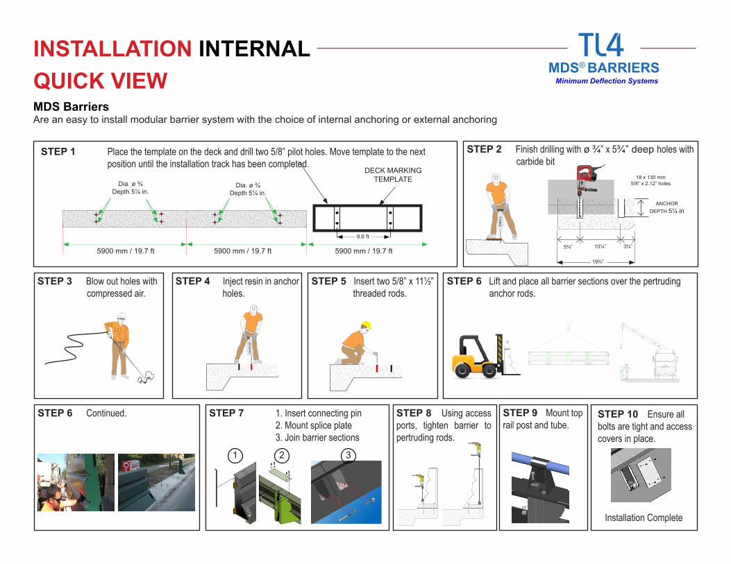
INSTALLATION INTERNALQUICK VIEWMDS Barriers Are an easy to install modular barrier system with the choice of internal anchoring or external anchoring
STEP 1 Place the template on the deck and drill two 5/8” pilot holes. Move template to the next position until the installation track has been completed.
STEP 2 Finish drilling with ø ¾” x 5¾” deep holes with carbide bit
STEP 3 Blow out holes with compressed air.
STEP 6 Continued. STEP 7 1. Insert connecting pin 2. Mount splice plate 3. Join barrier sections
STEP 8 Using access ports, tighten barrier to pertruding rods.
STEP 9 Mount top rail post and tube.
STEP 10 Ensure all bolts are tight and access covers in place.
STEP 4 Inject resin in anchor holes.
5900 mm / 19.7 ft 5900 mm / 19.7 ft 5900 mm / 19.7 ft
9.6 ft
Dia. ø ¾Depth 5¼ in.
Dia. ø ¾Depth 5¼ in.
DECK MARKING TEMPLATE
DR
ILL
18 x 130 mm5/8” x 2.12” holes
5¾” 10¼”
19¾”
3¾”
ANCHOR DEPTH 5¼ in
STEP 5 Insert two 5/8” x 11½” threaded rods.
STEP 6 Lift and place all barrier sections over the pertruding anchor rods.
AD
HES
IVE
1 2 3
Installation Complete

TL4MDS® BARRIERS
Minimum Deflection Systems
INSTALLATION EXTERNAL
MDS Barriers Are an easy to install modular barrier system with the choice of internal anchoring or external anchoring
STEP 1 Place external anchor plate under barrier and lock in throgh front access port holes.
STEP 3 Once barrier is in place, drill four ø ¾” x 5¼” deep through the quick release anchor plate.
STEP 4 Blow out holes with compressed air.
STEP 7 1. Insert connecting pin 2. Mount splice plate 3. Join barrier sections
STEP 8 Using access ports, tighten barrier to pertruding rods.
STEP 9 Mount top rail post and tube.
STEP 10 Ensure all bolts are tight and access covers in place.
STEP 5 Inject resin in anchor holes.
STEP 6 Insert two 5/8” x 11½” threaded rods.
STEP 2 Lift and place all barrier sections according to project layout and design.
1 2 3
Installation Complete
SECTION A SECTION A
DR
ILL
AD
HES
IVE
Front
Rear
QUICK VIEW

®
MDS® BARRIERS43 Franklin St East Hartford, CT. 06108
Toll Free: 888-906-9327 Tel: 860-906-3390
email: [email protected] www.jerseybarriers.com
Page 11