en1317-5 - parapeti new jersey
DESCRIPTION
EN1317-5 - Parapeti New JerseyTRANSCRIPT
BRITISH STANDARD BS EN 1317-5:2007 +A1:2008
Road restraint systems —Part 5: Product requirements and evaluation of conformity for vehicle restraint systems
ICS 13.200; 93.080.30
�������������� ���������������������������������������������������Licensed copy:Arup, 25/02/2010, Uncontrolled Copy, © BSI
BS EN 1317-5:2007+A1:2008
This British Standard was published under the authority of the Standards Policy and Strategy Committee on 31 May 2007
© BSI 2008
ISBN 978 0 580 59372 7
National foreword
This British Standard is the UK implementation of EN 1317-5:2007+A1:2008. It supersedes BS EN 1317-5:2007 which is withdrawn.The start and finish of text introduced or altered by amendment is indicated in the text by tags. Tags indicating changes to CEN text carry the number of the CEN amendment. For example, text altered by CEN amendment A1 is indicated by .The UK participation in its preparation was entrusted by Technical Committee B/509, Road equipment, to Subcommittee B/509/1, Road restraint systems. A list of organizations represented on this subcommittee can be obtained on request to its secretary. EN 1317-5:2007 is a candidate ‘‘harmonized’’ European Standard and fully takes into account the requirements of the European Commission mandate M/111, Circulation fixtures, given under the EU Construction Products Directive (89/106/EEC), and is intended to lead to CE marking. The date of applicability of EN 1317-5:2007 as a ‘‘harmonized’’ European Standard, i.e. the date after which this standard may be used for CE marking purposes, is subject to an announcement in the Official Journal of the European Communities.EN 1317-5:2007 is the subject of transitional arrangements agreed under the European Commission mandate. The Member States have agreed a nominal transition period for the co-existence of EN 1317-5:2007 and their corresponding national standard(s). It is intended that this period will comprise a nominal nine-month period during which any required changes to national regulations are to be made, followed by a further nominal thirty-six-month period for the implementation of CE marking. At the end of this co-existence period, the national standard(s) will be withdrawn. In the UK, the corresponding national standards are:
— BS 6779-1:1998, Highway parapets for bridges and other structures. Specification for vehicle containment parapets of metal construction;
— BS 6779-2:1991, Highway parapets for bridges and other structures. Specification for vehicle containment parapets of concrete construction;
— BS 6779-3:1994, Highway parapets for bridges and other structures. Specification for vehicle containment parapets of combined metal and concrete construction;and based on this nominal transition period of forty-five months, BS 6779-1:1998, BS 6779-2:1991 and BS 6779-3:1994 would be withdrawn in January 2011. NOTE: This date is approximate. Users of this standard should contact BSI Customer Services for confirmation of withdrawal. This publication does not purport to include all the necessary provisions of a contract. Users are responsible for its correct application. Compliance with a British Standard cannot confer immunity from legal obligations.
Amendments/corrigenda issued since publication
Date Comments
30 September 2008 Implementation of CEN amendment A1:2008
Licensed copy:Arup, 25/02/2010, Uncontrolled Copy, © BSI
EUROPEAN STANDARD
NORME EUROPÉENNE
EUROPÄISCHE NORM
EN 1317-5:2007+A1
July 2008
ICS 13.200; 93.080.30 Supersedes EN 1317-5:2007
English Version
Road restraint systems - Part 5: Product requirements and evaluation of conformity for vehicle restraint systems
Dispositifs de retenue routiers - Partie 5: Exigences relatives aux produits et évaluation de la conformité pour
les dispositifs de retenue pour véhicules
Rückhaltesysteme an Straßen - Teil 5: Anforderungen an die Produkte, Konformitätsverfahren und -bescheinigung für
Fahrzeugrückhaltesysteme
This European Standard was approved by CEN on 28 September 2006 and includes Amendment 1 approved by CEN on 30 May 2008.
CEN members are bound to comply with the CEN/CENELEC Internal Regulations which stipulate the conditions for giving this EuropeanStandard the status of a national standard without any alteration. Up-to-date lists and bibliographical references concerning such national standards may be obtained on application to the CEN Management Centre or to any CEN member.
This European Standard exists in three official versions (English, French, German). A version in any other language made by translation under the responsibility of a CEN member into its own language and notified to the CEN Management Centre has the same status as the official versions.
CEN members are the national standards bodies of Austria, Belgium, Bulgaria, Cyprus, Czech Republic, Denmark, Estonia, Finland,France, Germany, Greece, Hungary, Iceland, Ireland, Italy, Latvia, Lithuania, Luxembourg, Malta, Netherlands, Norway, Poland, Portugal, Romania, Slovakia, Slovenia, Spain, Sweden, Switzerland and United Kingdom.
EUROPEAN COMMITTEE FOR STANDARDIZATION C O M I T É E U R O P É E N D E N O R M A LI S A T I O N EUR OP ÄIS C HES KOM ITEE FÜR NOR M UNG
Management Centre: rue de Stassart, 36 B-1050 Brussels
© 2008 CEN All rights of exploitation in any form and by any means reserved worldwide for CEN national Members.
Ref. No. EN 1317-5:2007+A1:2008: E
Licensed copy:Arup, 25/02/2010, Uncontrolled Copy, © BSI
EN 1317-5:2007+A1:2008 (E)
2
Contents
Page
Foreword......................................................................................................................................................................3
Introduction .................................................................................................................................................................4
1 Scope ..............................................................................................................................................................5
2 Normative references ....................................................................................................................................5
3 Terms and definitions ...................................................................................................................................6
4 Requirements .................................................................................................................................................64.1 Performance under impact ...........................................................................................................................64.2 Height of combined vehicle/ pedestrian parapets......................................................................................74.3 Durability ........................................................................................................................................................7
5 Technical description of the vehicle restraint system (VRS)....................................................................85.1 General............................................................................................................................................................85.2 Product description.......................................................................................................................................85.3 Details of system modifications...................................................................................................................85.4 Installation requirements ..............................................................................................................................8
6 Evaluation of conformity...............................................................................................................................96.1 General............................................................................................................................................................96.2 Type testing....................................................................................................................................................96.3 Factory Production Control (FPC) .............................................................................................................116.4 Prototype products......................................................................................................................................13
7 Cases of technical specification non-compliance ...................................................................................13
8 Installation of road restraint systems........................................................................................................13
Annex A (normative) Modification of VRS tested in accordance with EN 1317-1, EN 1317-2 + EN 1317-2/A1, EN 1317-3 or ENV 1317-4...................................................................................................................14
Annex B (informative) Example list of cases of possible modifications to the requirements of Clauses 4, 5 and 6........................................................................................................................................17
Annex ZA (informative) Clauses of this European Standard addressing the provisions of the EU Construction Products Directive................................................................................................................19
Bibliography ..............................................................................................................................................................33
BS EN 1317-5:2007+A1:2008Licensed copy:Arup, 25/02/2010, Uncontrolled Copy, © BSI
EN 1317-5:2007+A1:2008 (E)
3
Foreword
This document (EN 1317-5:2007+A1:2008) has been prepared by Technical Committee CEN/TC 226 “Road equipment”, the secretariat of which is held by AFNOR.
This European Standard shall be given the status of a national standard, either by publication of an identical text or by endorsement, at the latest by January 2009 and conflicting national standards shall be withdrawn at the latest by January 2011.
This document includes Amendment 1, approved by CEN on 2008-05-30.
This document supersedes EN 1317-5:2007.
The start and finish of text introduced or altered by amendment is indicated in the text by tags ! ".
This document has been prepared under a mandate given to CEN by the European Commission and the European Free Trade Association, and supports essential requirements of EU Directive(s).
For relationship with EU Directive(s), see informative Annex ZA, which is an integral part of this document.
This European Standard consists of this document and the following parts under the general title: Road restraint systems.
⎯ Part 1: Terminology and general criteria for test methods
⎯ Part 2: Performance classes, impact test acceptance criteria and test methods for safety barriers
⎯ Part 3: Performance classes, impact test acceptance criteria and test methods for crash cushions
⎯ Part 4: Performance classes, impact test acceptance criteria and test methods for terminals and transitions of safety barriers
⎯ Part 6: Pedestrian restraint system
According to the CEN/CENELEC Internal Regulations, the national standards organizations of the following countries are bound to implement this European Standard: Austria, Belgium, Bulgaria, Cyprus, Czech Republic, Denmark, Estonia, Finland, France, Germany, Greece, Hungary, Iceland, Ireland, Italy, Latvia, Lithuania, Luxembourg, Malta, Netherlands, Norway, Poland, Portugal, Romania, Slovakia, Slovenia, Spain, Sweden, Switzerland and the United Kingdom.
BS EN 1317-5:2007+A1:2008Licensed copy:Arup, 25/02/2010, Uncontrolled Copy, © BSI
EN 1317-5:2007+A1:2008 (E)
4
Introduction
This document is a product standard for vehicle restraint systems placed on the market.
This document is designed for use in conjunction with Parts 1, 2, 3, prEN 1317-6 or ENV 1317-4.
To ensure the full performance of road restraint systems in use, their production and installation is intended to be controlled in accordance with this document.
BS EN 1317-5:2007+A1:2008Licensed copy:Arup, 25/02/2010, Uncontrolled Copy, © BSI
EN 1317-5:2007+A1:2008 (E)
5
1 Scope
This European Standard specifies requirements for evaluation of conformity of the following vehicle restraint systems:
a) safety barriers;
b) crash cushions;
c) terminals (will be effective when ENV 1317-4 becomes an EN);
d) transitions (will be effective when ENV 1317-4 becomes an EN);
e) vehicle / pedestrian parapets (only for the vehicle restraint function).
Pedestrian parapet requirements are not covered in this document.
Requirements for the evaluation of durability with respect to weathering are included in this document.
Requirements for other forms of durability (e.g. marine environment, sand abrasion) are not included.
Temporary barriers are not within the scope of this document.
2 Normative references
The following referenced documents are indispensable for the application of this document. For dated references, only the edition cited applies. For undated references, the latest edition of the referenced document (including any amendments) applies.
EN 206-1, Concrete – Part 1: Specification, performance, production and conformity
!EN 335-1, Durability of wood and wood-based products – Definition of use classes – Part 1: General
EN 335-2, Durability of wood and wood-based products – Definition of use classes – Part 2: Application to solid wood"
EN 1317-1, Road restraint systems – Part 1: Terminology and general criteria for test methods
EN 1317-2, Road restraint systems – Part 2: Performance classes, impact test acceptance criteria and test methods for safety barriers
EN 1317-2/A1, Road restraint systems – Part 2: Performance classes, impact test acceptance criteria and test methods for safety barriers
EN 1317-3, Road restraint systems – Part 3: Performance classes, impact test acceptance criteria and test methods for crash cushions
ENV 1317-4, Road restraint systems – Part 4: Performance classes, impact test acceptance criteria and test methods for terminals and transitions of safety barriers
prEN 1317-6, Road restraint systems – Pedestrian restraint systems, pedestrian parapet
EN 10326, Continuously hot-dip zinc coated strip and sheet of structural steels – Technical delivery conditions
EN 13369, Common rules for precast concrete products
BS EN 1317-5:2007+A1:2008Licensed copy:Arup, 25/02/2010, Uncontrolled Copy, © BSI

EN 1317-5:2007+A1:2008 (E)
6
EN ISO 1461, Hot dip galvanized coatings on fabricated iron and steel articles – Specifications and test methods (ISO 1461:1999)
EN ISO 9001:2000, Quality managements systems – Requirements (ISO 9001:2000)
3 Terms and definitions
For the purposes of this European Standard, the following terms and definitions apply.
3.1testing laboratory competent laboratory, which measures, examines, tests, calibrates or otherwise determines the characteristics or performance of materials or products within the scope of this document. A laboratory accredited by a signatory of EA (European co-operation for accreditation) or the appropriate statutory instrument, within the scope of this document, in the territory where the test was executed may be presumed to be competent
3.2working life period of time during which the performance of a product will be maintained at a level that enables the product to fulfil the requirements of this document (i.e. the essential characteristics of a product to meet or exceed minimum acceptable values, without incurring major costs for repair or replacement). The working life of a product depends upon its inherent durability and normal maintenance
NOTE A clear distinction should be made between the assumed economically reasonable working life for a product, which underlies the assessment of durability in technical specifications, and the actual working life of a product in a works. The latter depends on many factors beyond the control of the producer, such as design, location of use (exposure), installation, use and maintenance. The assumed working life can thus not be interpreted as being a guarantee given by the producer.
3.3durability ability of a product to maintain its required performance over time, under the influence of foreseeable actions. Subject to normal maintenance, a product should enable properly designed and executed works to fulfil specified requirements for an economically reasonable working life of the product
3.4manufacturer (synonymous with “producer”) organization with legal responsibility for placing a CE-Mark on a product (see Annex ZA)
4 Requirements
4.1 Performance under impact
4.1.1 Safety barriers
Safety barriers shall be tested to and shall conform to the requirements of EN 1317-1 and EN 1317-2 + EN 1317-2/A1.
4.1.2 Vehicle parapets
Vehicle parapets shall be tested to and shall conform to the requirements of EN 1317-1 and EN 1317-2 + EN 1317-2/A1.
4.1.3 Crash cushions
Crash cushions shall be tested to and shall conform to the requirements of EN 1317-1 and EN 1317-3.
BS EN 1317-5:2007+A1:2008Licensed copy:Arup, 25/02/2010, Uncontrolled Copy, © BSI

EN 1317-5:2007+A1:2008 (E)
7
4.1.4 Terminals
Terminals shall be tested to and shall conform to the requirements of EN 1317-1 and ENV 1317-4 (will be effective when ENV 1317-4 becomes an EN).
4.1.5 Transitions
Transitions shall be tested to and shall conform to the requirements of EN 1317-1 and ENV 1317-4 (will be effective when ENV 1317-4 becomes an EN).
4.1.6 Combined vehicle / pedestrian parapets
Vehicle / pedestrian parapets shall be tested to and shall conform to the requirements of EN 1317-1 and EN 1317-2 + EN 1317-2/A1 and prEN 1317-6 (will be effective when prEN 1317-6 becomes an EN).
4.1.7 Threshold levels
Vehicle restraint systems shall conform to the minimum threshold levels defined in Table 1.
Table 1 – Minimum threshold levels for vehicle restraint systems
Safety barriers EN 1317-2 (in accordance with Table 2) N1
Crash cushions EN 1317-3 (in accordance with Table 3) Class 50
Terminals ENV 1317-4 (in accordance with Table 1) P1
Transitions ENV 1317-4 (in accordance with 4.2) N1
Combined vehicle/parapets
EN 1317-2 (in accordance with Table 2) and prEN 1317-6 N1
4.2 Height of combined vehicle/ pedestrian parapets
The height of combined vehicle / pedestrian parapets shall conform to prEN 1317-6 (will be effective when prEN 1317-6 becomes an EN).
4.3 Durability
All vehicle restraint systems shall be durable for an economically reasonable working life, for which a reviewable experience-based description and / or related measurements of durability shall be adequate.
Road restraint systems can have foundation systems, the economically reasonable working life of which relates to the supporting structure, and this needs to be reported separately to that of the road restraint system if supplied by the VRS manufacturer.
a) Manufacturer shall declare the materials and protective coatings used on the road restraint system;
b) manufacturer shall declare an assessment of durability including the identification of technical characteristics of materials affecting durability, and the methods of evaluation (e.g. coating mass determination, adhesion testing).
Issues affecting durability may include the following examples:
c) specification of protective coating in accordance with EN ISO 1461 and EN 10326 and/or level of treatment of materials;
BS EN 1317-5:2007+A1:2008Licensed copy:Arup, 25/02/2010, Uncontrolled Copy, © BSI

EN 1317-5:2007+A1:2008 (E)
8
d) composition and thickness of material in accordance with EN 206-1 for concrete and EN 13369 for precast concrete;
e) !specification of wood treatment and or/natural durability of wood to be used in use classes specified in EN 335-1 and EN 335-2;"
f) recommendations on installation conditions in the works in the case of onerous site conditions;
g) specified maintenance requirements (important in harsh environments).
NOTE The working life of a road restraint system depends upon its inherent durability and the prevailing environmental conditions. A clear distinction should be made between the (declared) working life for a product, based on the assessment of durability in technical specifications, and the actual working life of a product. The latter depends on many factors beyond thecontrol of the manufacturer, such as installation design, environmental location, handling, use, and maintenance.
5 Technical description of the vehicle restraint system (VRS)
5.1 General
The manufacturer shall provide the following information.
5.2 Product description
a) general system arrangement drawings with installation layout assembly descriptions and tolerances;
b) drawings of all component geometries with dimensions, tolerances, and all material specifications;
c) specifications for all materials and all finishes (including protective treatment system);
d) assessment of durability of the product;
e) drawings of all components sub-assembled in the factory;
f) complete parts list, including weights;
g) details of pre-stressing (if relevant);
h) any other relevant information (e.g. recycling information, environment, security);
i) information on regulated substances.
5.3 Details of system modifications
Details of system modifications approved since the ITT (Initial Type Testing).
5.4 Installation requirements
a) assembly drawings, of the product tested, including tolerances;
b) description of the installation works, including equipment;
c) procedures for installation (erection, assembly, foundations, etc.) as set out in the installation manual;
d) ambient temperature at time of installation (if relevant);
e) details of tensioning (if relevant);
f) description of the soil conditions and/or foundations suitable for the system;
BS EN 1317-5:2007+A1:2008Licensed copy:Arup, 25/02/2010, Uncontrolled Copy, © BSI

EN 1317-5:2007+A1:2008 (E)
9
g) provisions for repair, inspection and maintenance;
h) any other relevant recycling information, details of toxic or dangerous materials present in the works.
NOTE Road restraint systems installed on bridges should be classified in accordance with EN 1991-2 regarding their impact loads.
6 Evaluation of conformity
6.1 General
The conformity of the road restraint system to the requirements of this document and with the stated values (including classes) shall be demonstrated by:
⎯ Initial Type Testing (ITT);
⎯ Factory Production Control (FPC) by the manufacturer, including product assessment.
For the purposes of testing, road restraint systems may be grouped into families as defined in EN 1317-2 + EN 1317-2/A1 and EN 1317-3 or ENV 1317-4, where it is considered that the selected property/properties is/are common to all road restraint systems within that family (for example, crash cushions conforming to this document).
6.2 Type testing
6.2.1 Initial Type Testing (ITT)
6.2.1.1 General
An initial type test is the complete set of tests conforming to EN 1317-1 and EN 1317-2 + EN 1317-2/A1, EN 1317-3 or ENV 1317-4. To demonstrate conformity with this document an ITT shall be performed on each VRS. Modified products shall be evaluated in accordance with 6.2.1.5.
6.2.1.2 Information required in the ITT
As a minimum, the manufacturer shall provide the information for assessment in accordance with 5.2 and 5.3, the full-scale vehicle impact test report and the evaluation report of the tested item.
6.2.1.3 Evaluation report of test item
The evaluation report shall comprise the following information:
a) verification that materials are as specified by the manufacturer in accordance with 5.2;
b) verification that geometries and dimensions are as specified by the manufacturer in accordance with 5.2;
c) verification of protective treatments, if any;
d) soils and foundations report relating to the ITT;
e) verification that the product is installed in accordance with the specified layout in accordance with 5.4.
6.2.1.4 Initial Type Test report
The ITT report shall include the following information as a minimum:
BS EN 1317-5:2007+A1:2008Licensed copy:Arup, 25/02/2010, Uncontrolled Copy, © BSI

EN 1317-5:2007+A1:2008 (E)
10
a) impact test report to EN 1317-1, EN 1317-2 + EN 1317-2/A1, EN 1317-3 or ENV 1317-4;
b) technical description of the road restraint system as in 5.2;
c) evaluation report as in 6.2.1.3.
6.2.1.5 Modified products
Implications of any modifications to an ITT tested system shall be evaluated and declared in respect of the effect on the performance of the road restraint system:
a) manufacturer shall describe the modifications brought to the drawings and specifications of the VRS, which had been subjected to the Initial Type Testing for the evaluation of the performance of the initial product;
b) modified product will be tested and assessed in accordance with Annex A.
6.2.1.6 Characteristics
All characteristics in 4.1 shall be subject to initial type testing. Release of dangerous substances may be assessed indirectly by controlling the content of the substance concerned.
6.2.1.7 Use of existing impact test reports (historical data)
In order to facilitate the use of existing road restraint systems which have been tested in accordance with EN 1317 before the availability of harmonized European Standards and to avoid unnecessary duplication of cost and possible delays, which could result in lower safety for users, existing systems may be accepted as meeting regulatory requirements without new impact tests by the use of historic data under the following conditions:
a) road restraint system shall have been assessed by a testing laboratory in accordance with existing or a former version of EN 1317-1, EN 1317-2 + EN 1317-2/A1, EN 1317-3 or ENV 1317-4 or a prEN 1317 standard, and the test results and possible additional information show that the road restraint system conforms to the requirements of this document;
b) provisions of this clause shall be invoked within 3 years after the end of the co existence period.
6.2.1.8 Shared ITT results
An individual manufacturer may use the ITT results obtained by another party, for example carried out by industry or a designer, on a product that he considers to be the same, provided that the following conditions are fulfilled:
a) manufacturer is able to demonstrate that the product is identical (e.g. has the same dimensions, the same raw materials and the same components) with the one that has been subjected to ITT;
b) party who has performed the test has agreed to give the results and has provided the report of the test to the manufacturer who will use the test result for his own ITT.
c) manufacturer, who uses the ITT results obtained by someone else to demonstrate his own declaration of conformity, remains responsible for the product being in compliance with all the requirements of this document, including both the design1 and the manufacture of the product.
NOTE This does not mean a “shared ITT”. An ITT concerns the evaluation of a specific product made by a given manufacturer. In the declaration of conformity established by the manufacturer, which is a document with legal status, the product is identified and the name of the manufacturer is given. Therefore, ITT cannot be shared, only results of testing.
1 For specific products (e.g. for design using Eurocodes) special provisions may apply.
BS EN 1317-5:2007+A1:2008Licensed copy:Arup, 25/02/2010, Uncontrolled Copy, © BSI
EN 1317-5:2007+A1:2008 (E)
11
6.2.2 Sampling
Initial Type Testing shall be performed on samples representative of the road restraint system to be placed on the market.
6.3 Factory Production Control (FPC)
6.3.1 General
The manufacturer shall establish, document and maintain an FPC system to ensure that the products placed on the market conform to the declared performance characteristics. The FPC system shall consist of written procedures (works' manual), regular inspections and tests and/or assessments and the use of the results to control raw and other incoming materials or components, equipment, the production process and the product. Records shall remain legible, readily identifiable and retrievable.
An FPC system conforming to the requirements of EN ISO 9001 and made specific to the requirements of this document shall be considered to satisfy the above requirements.
The results of inspections, tests or assessments requiring action shall be recorded, as shall any action taken. The action to be taken when control values or criteria are not met shall be recorded and retained for the period specified in the manufacturer’s FPC procedures.
The manufacturer may delegate to a management representative the responsibility and authority for:
a) effective identification of non-conformities, and implementation of their rectification;
b) revision of the Factory Production Control system to correct identified causes of non-conformity, when necessary;
c) effective implementation of a traceability method as defined in this document.
6.3.2 Factory Production Control (FPC) requirements
The Initial inspection is for the purpose of determining whether the resources, in terms of staff and equipment together with procedures for process control to the proposed Factory Production Control plan, are in place to assure conformity of the product with the technical specifications.
The manufacturer shall establish procedures to ensure that the production tolerances allow for the road restraint systems' performances to conform to the declared values, derived from initial type testing. The minimum frequency for component testing and evaluation as part of FPC is once a year.
The manufacturer shall record the results. These records shall at least include the following information:
a) identification of the road restraint systems tested;
b) date of sampling and testing;
c) test methods performed;
d) test results.
BS EN 1317-5:2007+A1:2008Licensed copy:Arup, 25/02/2010, Uncontrolled Copy, © BSI
EN 1317-5:2007+A1:2008 (E)
12
6.3.3 Manufacturer-specific FPC system requirements
6.3.3.1 Personnel
The responsibility, authority and the relationship between personnel that manages, performs or verifies work affecting product conformity, shall be defined. This applies in particular to personnel who need to initiate actions preventing product non-conformities from occurring, actions in case of non-conformities and to identify and register product conformity problems. Personnel performing work affecting product conformity shall be competent on the basis of appropriate education, training, skills and experience for which records shall be maintained.
6.3.3.2 Equipment
All weighing, measuring and testing equipment necessary to achieve, or produce evidence of, conformity shall be calibrated or verified and regularly inspected in accordance with documented procedures, frequencies and criteria. Control of monitoring and measuring devices shall conform to the appropriate clause of EN ISO 9001.
All equipment used in the manufacturing process shall be regularly inspected and maintained to ensure use, wear or failure does not cause inconsistency in the manufacturing process.
Inspection and maintenance shall be carried out and recorded in accordance with the manufacturer’s written procedures and the records retained for the period defined in the manufacturer's FPC procedures.
6.3.3.3 Raw materials and components
The specifications of all incoming raw materials and components shall be documented, as shall the inspection scheme for ensuring their conformity. The verification of conformity of the raw material with the specification shall be in accordance with EN ISO 9001:2000, 7.4.3.
In the case where supplied components are used, the attestation of conformity level should at least coincide with that of the road restraint system. If this is not the case, the inspection scheme should be raised to obtain that level.
The manufacturer shall plan and carry out production under controlled conditions. Compliance with EN ISO 9001:2000, 7.5.1 and 7.5.2 shall be deemed to satisfy the requirements of this clause.
6.3.3.4 Traceability and marking
Individual road restraint systems shall be identifiable and traceable with regard to their production origin. The manufacturer shall have procedures ensuring that processes related to affixing traceability codes and/or markings are inspected regularly. Documented traceability records shall be available for at least 5 years from the date of manufacture. Compliance with EN ISO 9001:2000, 7.5.3 shall be deemed to satisfy the requirements of this clause.
6.3.3.5 Non-conforming products
The manufacturer shall have written procedures, which specify how non-conforming products shall be dealt with. Any such events shall be recorded as they occur and these records shall be kept for the period defined in the manufacturer’s written procedures. Compliance with EN ISO 9001:2000, 8.3 shall be deemed to satisfy the requirements of this clause.
6.3.3.6 Corrective action
The manufacturer shall have documented procedures that instigate action to eliminate the cause of non-conformities in order to prevent recurrence. Compliance with EN ISO 9001:2000, 8.5.2 shall be deemed to satisfy the requirements of this clause.
BS EN 1317-5:2007+A1:2008Licensed copy:Arup, 25/02/2010, Uncontrolled Copy, © BSI

EN 1317-5:2007+A1:2008 (E)
13
In cases where non-compliance with the road restraint system and/or components specifications are identified or defects have been revealed in the manufacturing process(es) or in the Factory Production Control, the manufacturer shall demonstrate that he/she has traced and rectified the defect(s). In the case of non-conformity the time scale shall ensure no defective safety critical product is presented to the market.
If no demonstrable rectification is achieved, the FPC shall be deemed non compliant with the requirements of this document. This time scale may be extended if neither the performance under impact in accordance with 4.1, nor the durability in accordance with 4.3 is adversely affected by the non-compliance.
6.3.3.7 Handling, storage, packaging
The manufacturer shall have procedures providing methods of product handling and shall provide suitable storage areas preventing damages or deterioration all conforming to EN ISO 9001.
6.4 Prototype products
For prototypes where the intention is to move to series production and before the series production is running the following shall be assessed:
a) FPC-documentation;
b) factory.
The initial assessment of the factory and FPC shall include:
c) verification that all resources necessary for the achievement of the product characteristics required by this document can be available;
d) verification that the FPC-procedures in accordance with the FPC-documentation can be implemented and followed in practice.
Once series production is fully established, the provisions of 6.3 shall apply.
7 Cases of technical specification non-compliance
In cases where non-compliance with the Road Restraint System and /or components specifications are identified or defects have been revealed in the manufacturing process(es) or in the Factory Production Control, the manufacturer shall demonstrate that any non conformance can be traced and rectified within a time that would preclude the release of defective product into the market.
8 Installation of road restraint systems
The manufacturer shall provide an installation manual for the installation that will achieve the performance declared for the ITT.
Details of maintenance and inspection, as specified in 5.3, shall be included in the Installation Manual.
The use of the system relative to soil and other conditions of installation shall be defined by the manufacturer.
Systems are deemed to conform to the ITT only if they are in accordance with the manufacturer's details for road restraint systems as specified in the Installation Manual for the following:
a) erection;
b) maintenance;
c) inspection;
d) soils.
BS EN 1317-5:2007+A1:2008Licensed copy:Arup, 25/02/2010, Uncontrolled Copy, © BSI
EN 1317-5:2007+A1:2008 (E)
14
Annex A(normative)
Modification of VRS tested in accordance with EN 1317-1, EN 1317-2 + EN 1317-2/A1, EN 1317-3 or ENV 1317-4
A.1 General
This annex gives rules for evaluation of conformity concerning Parts 1, 2, 3, 4 of an approved VRS, which has been modified and methods by which to demonstrate the extent to which the modification has changed its performance.
NOTE After Initial Type Testing, VRS may be altered on the basis of new technology and knowledge whereby improvements and modification of their components can take place.
In some cases, as specified in A.4 and A.5, a VRS may be evaluated by a reduced number of impact tests or by calculations, computer simulations or simple loading tests.
A.2 Modified VRS
A modified VRS is a VRS that previously conformed to this document, which has been changed by material design or dimension in such a way that can affect characteristics, which are subject to requirements in this document.
NOTE 6.2.1.5 of this part provides requirements for evaluating the effect of modifications.
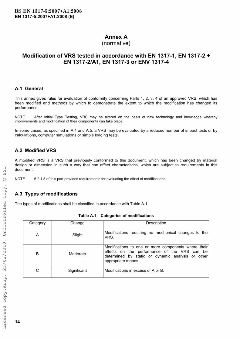
A.3 Types of modifications
The types of modifications shall be classified in accordance with Table A.1.
Table A.1 – Categories of modifications
Category Change Description
A Slight Modifications requiring no mechanical changes to the VRS.
B Moderate
Modifications to one or more components where their effects on the performance of the VRS can be determined by static or dynamic analysis or other appropriate means.
C Significant Modifications in excess of A or B.
BS EN 1317-5:2007+A1:2008Licensed copy:Arup, 25/02/2010, Uncontrolled Copy, © BSI
EN 1317-5:2007+A1:2008 (E)
15
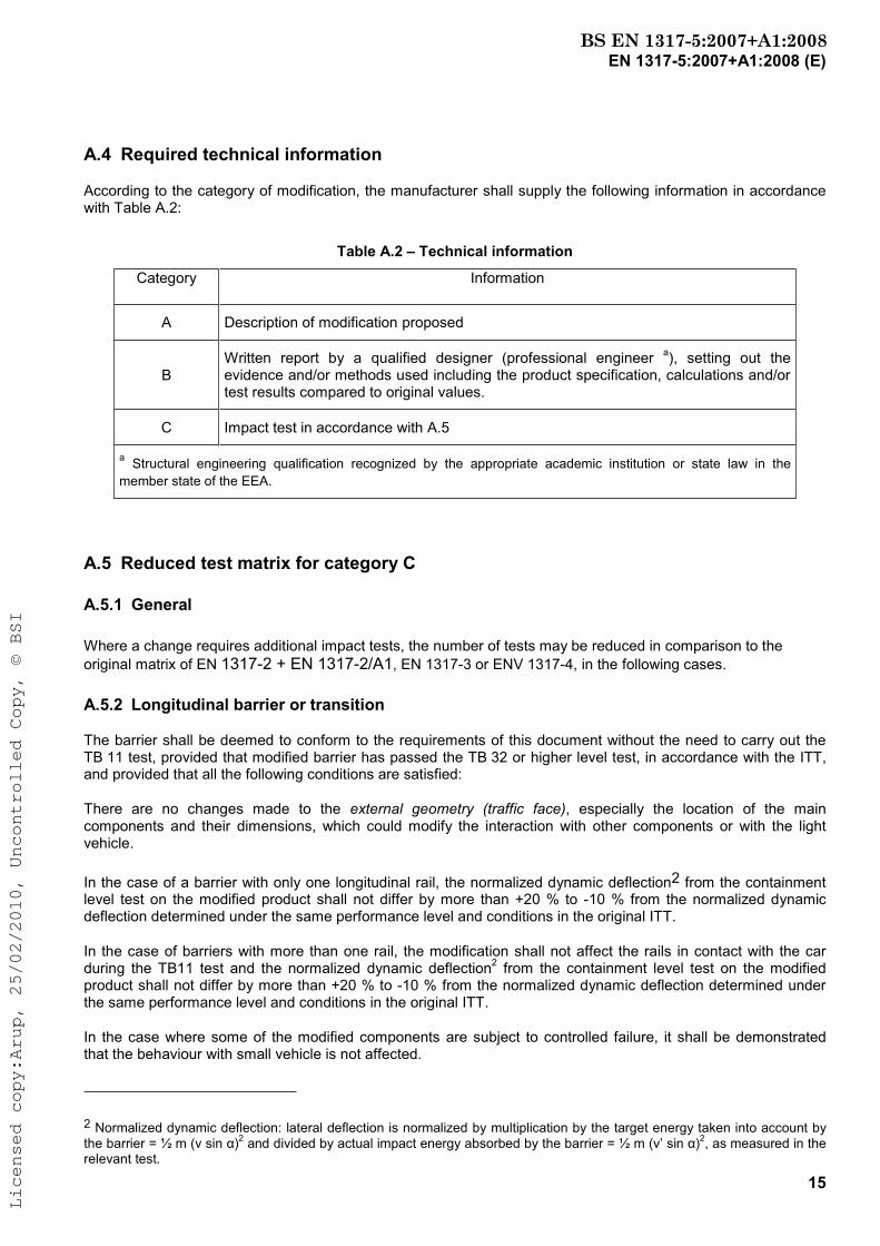
A.4 Required technical information
According to the category of modification, the manufacturer shall supply the following information in accordance with Table A.2:
Table A.2 – Technical information
Category Information
A Description of modification proposed
BWritten report by a qualified designer (professional engineer a), setting out the evidence and/or methods used including the product specification, calculations and/or test results compared to original values.
C Impact test in accordance with A.5
a Structural engineering qualification recognized by the appropriate academic institution or state law in the member state of the EEA.
A.5 Reduced test matrix for category C
A.5.1 General
Where a change requires additional impact tests, the number of tests may be reduced in comparison to the original matrix of EN 1317-2 + EN 1317-2/A1, EN 1317-3 or ENV 1317-4, in the following cases.
A.5.2 Longitudinal barrier or transition
The barrier shall be deemed to conform to the requirements of this document without the need to carry out the TB 11 test, provided that modified barrier has passed the TB 32 or higher level test, in accordance with the ITT, and provided that all the following conditions are satisfied:
There are no changes made to the external geometry (traffic face), especially the location of the main components and their dimensions, which could modify the interaction with other components or with the light vehicle.
In the case of a barrier with only one longitudinal rail, the normalized dynamic deflection2 from the containment level test on the modified product shall not differ by more than +20 % to -10 % from the normalized dynamic deflection determined under the same performance level and conditions in the original ITT.
In the case of barriers with more than one rail, the modification shall not affect the rails in contact with the car during the TB11 test and the normalized dynamic deflection2 from the containment level test on the modified product shall not differ by more than +20 % to -10 % from the normalized dynamic deflection determined under the same performance level and conditions in the original ITT.
In the case where some of the modified components are subject to controlled failure, it shall be demonstrated that the behaviour with small vehicle is not affected.
2 Normalized dynamic deflection: lateral deflection is normalized by multiplication by the target energy taken into account by the barrier = ½ m (v sin )2 and divided by actual impact energy absorbed by the barrier = ½ m (v’ sin )2, as measured in the relevant test.
BS EN 1317-5:2007+A1:2008Licensed copy:Arup, 25/02/2010, Uncontrolled Copy, © BSI
EN 1317-5:2007+A1:2008 (E)
16
A.5.3 Crash cushion
If the change is relative to the absorbing part only, the modified crash cushion shall be deemed to meet the requirements if it has passed the following test:
⎯ head on centre test with the heaviest vehicle used during ITT, at the maximum velocity class and minimum taper /width of the ITT group.
If the change is relative to the structure only, the modified crash cushion shall be deemed to meet the requirements if it has passed the following test:
⎯ side impact at 15° test with the heaviest vehicle used during ITT, at the maximum velocity class and maximum taper /width of the ITT group.
In the case where the structural change affects the collapse mechanisms and therefore stopping forces, a head on centre test as above is also required.
A.5.4 Terminal
If the change is relative to the absorbing part only, the modified terminal shall be deemed to meet the requirements if it has passed the following tests, depending on the modifications:
⎯ head on centre test with the heaviest vehicle used during ITT, at the maximum velocity class of the ITT group;
⎯ head on nose ¼ offset test.
In the case where the change is related to the structure only, the modified terminal shall be deemed to meet the requirements if it has passed the following tests, depending on the position of the modifications:
⎯ side, 15° 2/3 L test with the heaviest vehicle used during ITT, at the maximum velocity class of ITT;
⎯ head on nose ¼ offset test.
In cases where the structural change affects the collapse mechanism and therefore the stopping forces, a head on centre test as above is also required.
A.6 Computational mechanics
NOTE Computational mechanics, or computer simulation, and particularly those codes, which use finite element models for vehicles and VRS‘s are powerful and fast developing design tools.
In some cases, the behaviour of a modified product may be assessed by the modification of a model, which has been validated by the original ITT. This may be particularly useful in evaluating cases, which may not necessarily require additional impact tests or as a source of additional information when the number of tests has beenreduced.
This procedure requires the model to be validated by replicating the actual impact test condition with a good compliance.
Independent third party confirmation should be provided for all calculations where computer models are used.
BS EN 1317-5:2007+A1:2008Licensed copy:Arup, 25/02/2010, Uncontrolled Copy, © BSI
EN 1317-5:2007+A1:2008 (E)
17
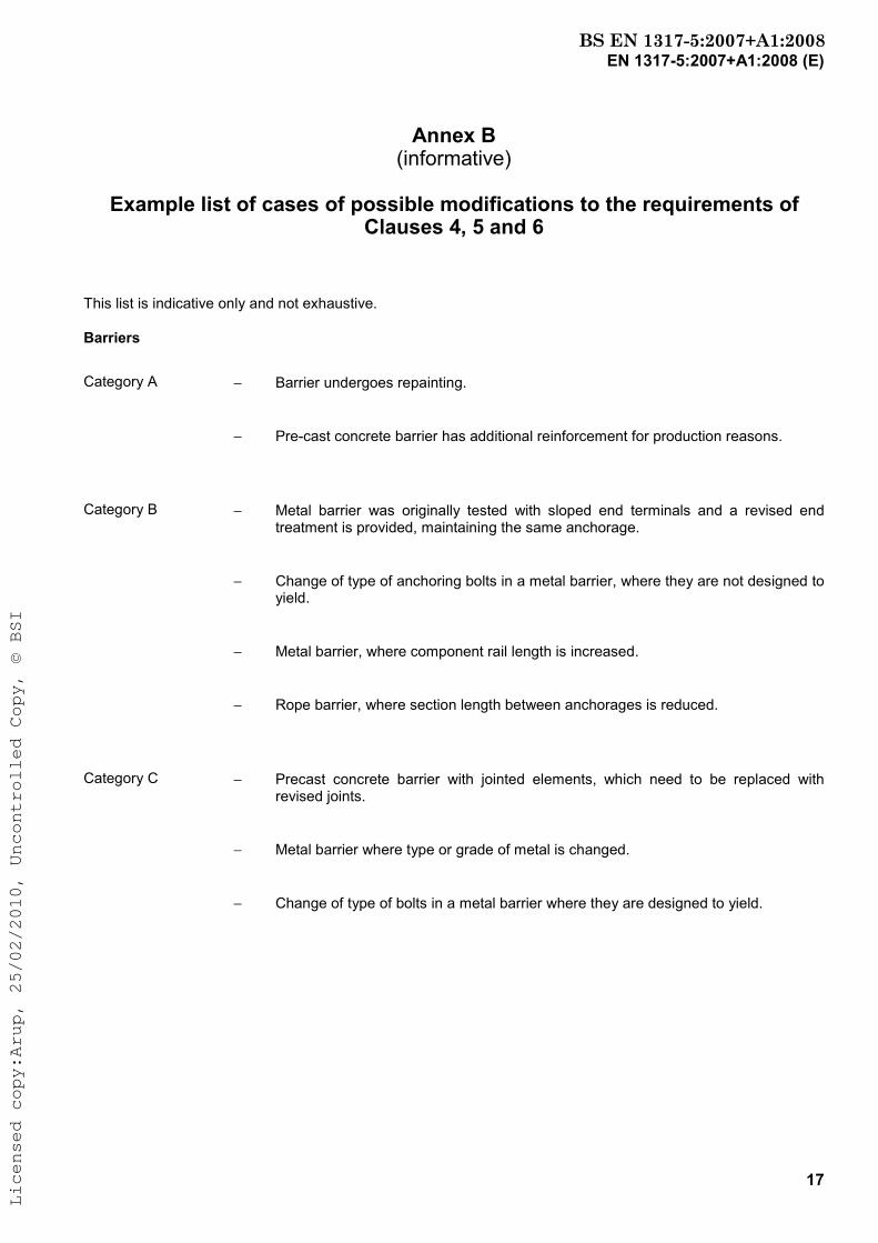
Annex B (informative)
Example list of cases of possible modifications to the requirements of Clauses 4, 5 and 6
This list is indicative only and not exhaustive.
Barriers
Category A − Barrier undergoes repainting.
− Pre-cast concrete barrier has additional reinforcement for production reasons.
Category B − Metal barrier was originally tested with sloped end terminals and a revised end treatment is provided, maintaining the same anchorage.
− Change of type of anchoring bolts in a metal barrier, where they are not designed to yield.
− Metal barrier, where component rail length is increased.
− Rope barrier, where section length between anchorages is reduced.
Category C − Precast concrete barrier with jointed elements, which need to be replaced with revised joints.
− Metal barrier where type or grade of metal is changed.
− Change of type of bolts in a metal barrier where they are designed to yield.
BS EN 1317-5:2007+A1:2008Licensed copy:Arup, 25/02/2010, Uncontrolled Copy, © BSI
EN 1317-5:2007+A1:2008 (E)
18
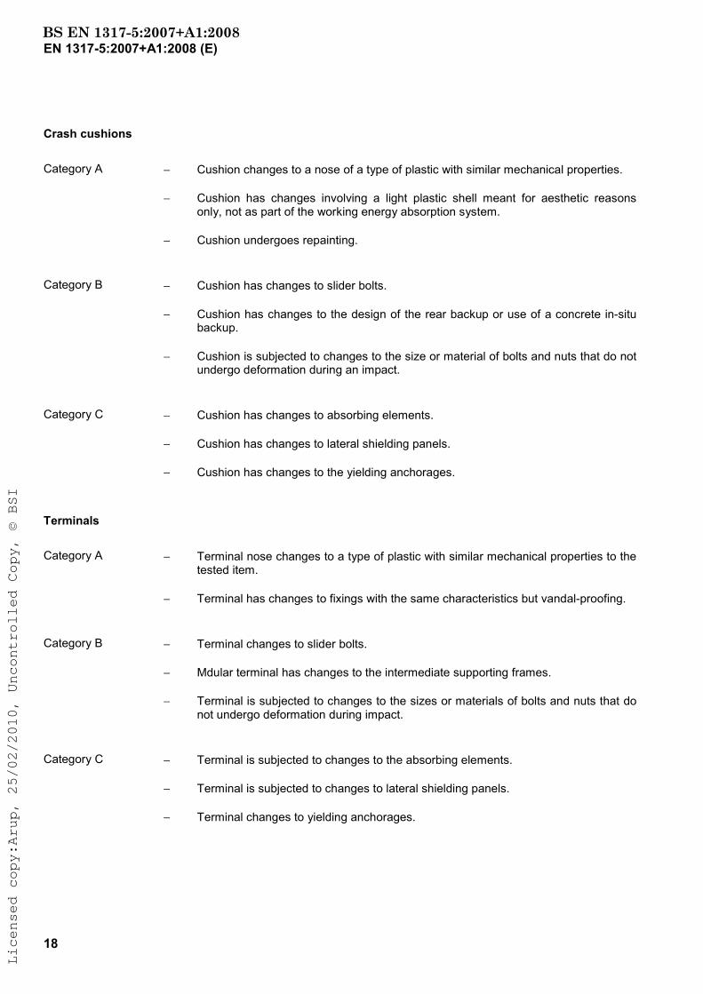
Crash cushions
Category A − Cushion changes to a nose of a type of plastic with similar mechanical properties.
− Cushion has changes involving a light plastic shell meant for aesthetic reasons only, not as part of the working energy absorption system.
− Cushion undergoes repainting.
Category B − Cushion has changes to slider bolts.
− Cushion has changes to the design of the rear backup or use of a concrete in-situ backup.
− Cushion is subjected to changes to the size or material of bolts and nuts that do not undergo deformation during an impact.
Category C − Cushion has changes to absorbing elements.
− Cushion has changes to lateral shielding panels.
− Cushion has changes to the yielding anchorages.
Terminals
Category A − Terminal nose changes to a type of plastic with similar mechanical properties to the tested item.
− Terminal has changes to fixings with the same characteristics but vandal-proofing.
Category B − Terminal changes to slider bolts.
− Mdular terminal has changes to the intermediate supporting frames.
− Terminal is subjected to changes to the sizes or materials of bolts and nuts that do not undergo deformation during impact.
Category C − Terminal is subjected to changes to the absorbing elements.
− Terminal is subjected to changes to lateral shielding panels.
− Terminal changes to yielding anchorages.
BS EN 1317-5:2007+A1:2008Licensed copy:Arup, 25/02/2010, Uncontrolled Copy, © BSI

EN 1317-5:2007+A1:2008 (E)
19
Annex ZA (informative)
Clauses of this European Standard addressing the provisions of the EU Construction Products Directive
ZA.1 Scope and relevant characteristics
This European Standard has been prepared under Mandate M/111 [Circulation Fixtures] given to CEN by the European Commission and the European Free Trade Association.
The clauses of this European Standard shown in this annex meet the requirements of the mandate given under the EU Construction Products Directive (89/106/EEC).
Compliance with these clauses confers a presumption of fitness of the [Road Restraint Systems] covered by this annex for the intended uses indicated herein; reference shall be made to the information accompanying the CE marking.
WARNING: Other requirements and other EU Directives, not affecting the fitness for intended uses, can be applicable to the construction products falling within the scope of this European Standard.
NOTE 1 In addition to any specific clauses relating to dangerous substances contained in this standard, there may be other requirements applicable to the products falling within its scope (e.g. transposed European legislation and national laws,regulations and administrative provisions). In order to meet the provisions of the EU Construction Products Directive, these requirements need also to be complied with, when and where they apply.
NOTE 2 An informative database of European and national provisions on dangerous substances is available at the Construction web site on EUROPA, accessed through http://europa.eu.int/comm/enterprise/construction/internal/dangsub/dangmain.htm.
This annex establishes the conditions for the CE marking of the construction products intended for the uses indicated in !Tables ZA.1.a to ZA.1.f" and shows the relevant clauses applicable:
This annex has the same scope as Clause 1 of this standard and is defined by Tables ZA.1.a to ZA.1.f.
BS EN 1317-5:2007+A1:2008Licensed copy:Arup, 25/02/2010, Uncontrolled Copy, © BSI

EN 1317-5:2007+A1:2008 (E)
20
Table ZA.1.a – Relevant clauses for vehicle restraint systems in circulation areas
Product: Vehicle restraint systems
Intended use: Alongside roads or in central reservations in circulation areas
Type of Vehicle Restraint System Requirement clauses in this and other European Standard(s)
Levels and/or classes
Notes
Performance under impact
Safety barriers
Crash cushions
Terminals
Transitions
Combined vehicle/pedestrian parapet
EN 1317-2 (98) + EN 1317-2/A1: 2006
EN 1317-3 (00)
ENV 1317-4 (01) a
ENV 1317-4 (02) a
prEN 1317-6 Aand EN 1317-2 (98) +EN 1317-2/A1:2006
None
See Table ZA.1b
See Table ZA.1c
See Table ZA.1d
See Table ZA.1e
See Table ZA.1f
Durability EN 1317-5:2005, 4.3 None - a Will be effective when ENV 1317-4 and prEN 1317-6 are published as EN’s.
Table ZA.1.b – Performance requirements for safety barriers
Product: Safety barrier
Intended use: Vehicle Restraint System for circulations areas
Essential characteristics Requirement clauses in this and other European Standard(s)
Levels and/or classes
Notes
Performance under impact
Containment level
Impact severity
Working width
Dynamic deflection
EN 1317-2:1998, 3.2 +EN 1317-2/A1:2006
EN 1317-2:1998, 3.3 +EN 1317-2/A1:2006
EN 1317-2:1998, 3.4 +EN 1317-2/A1:2006
EN 1317-2:1998, 3.4 +EN 1317-2/A1:2006
None
a) Class N1 … H4
b) Level A, B
c) metre (class)
d) metre
Durability EN 1317-5:2007, 4.3 None -
BS EN 1317-5:2007+A1:2008Licensed copy:Arup, 25/02/2010, Uncontrolled Copy, © BSI
EN 1317-5:2007+A1:2008 (E)
21
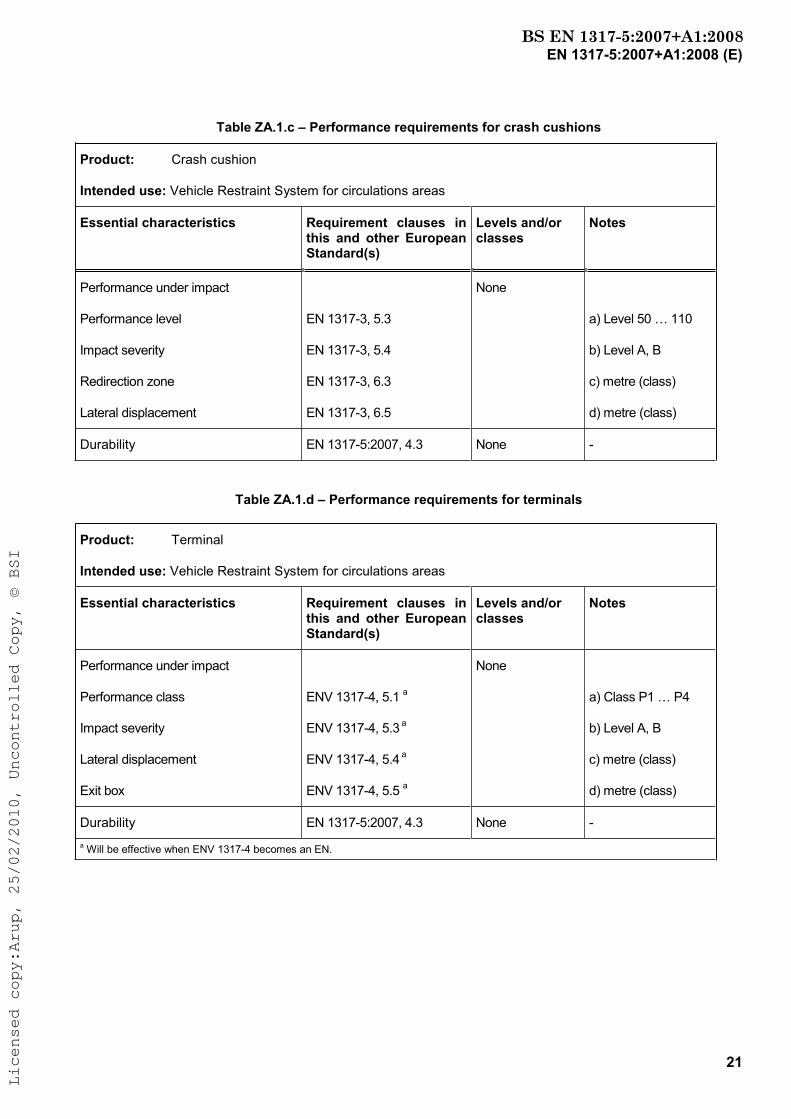
Table ZA.1.c – Performance requirements for crash cushions
Product: Crash cushion
Intended use: Vehicle Restraint System for circulations areas
Essential characteristics Requirement clauses in this and other European Standard(s)
Levels and/or classes
Notes
Performance under impact
Performance level
Impact severity
Redirection zone
Lateral displacement
EN 1317-3, 5.3
EN 1317-3, 5.4
EN 1317-3, 6.3
EN 1317-3, 6.5
None
a) Level 50 … 110
b) Level A, B
c) metre (class)
d) metre (class)
Durability EN 1317-5:2007, 4.3 None -
Table ZA.1.d – Performance requirements for terminals
Product: Terminal
Intended use: Vehicle Restraint System for circulations areas
Essential characteristics Requirement clauses in this and other European Standard(s)
Levels and/or classes
Notes
Performance under impact
Performance class
Impact severity
Lateral displacement
Exit box
ENV 1317-4, 5.1 a
ENV 1317-4, 5.3 a
ENV 1317-4, 5.4 a
ENV 1317-4, 5.5 a
None
a) Class P1 … P4
b) Level A, B
c) metre (class)
d) metre (class)
Durability EN 1317-5:2007, 4.3 None - a Will be effective when ENV 1317-4 becomes an EN.
BS EN 1317-5:2007+A1:2008Licensed copy:Arup, 25/02/2010, Uncontrolled Copy, © BSI

EN 1317-5:2007+A1:2008 (E)
22
Table ZA.1.e – Performance requirements for transitions Product: Transition Intended use: Vehicle Restraint System for circulations areas
Essential characteristics Requirement clauses in this and other European Standard(s)
Levels and/or classes
Notes
Performance under impact
Containment level
Impact severity
Working width
Dynamic deflection
ENV 1317-4:2001, 6.1 a
(EN 1317-2:1998, 3.2 +EN 1317-2/A1:2006)
ENV 1317-4:2001, 6.1 a
EN 1317-2:1998, 3.3 +EN 1317-2/A1:2006)
ENV 1317-4:2001, 6.1 a
EN 1317-2:1998, 3.4 +EN 1317-2/A1:2006)
ENV 1317-4:2001, 6.1 aEN 1317-2:1998, 3.4 +EN 1317-2/A1:2006)
None
a) Class N1 … H4
b) Level A, B
c) metre (class)
d) metre
Durability EN 1317-5:2007, 4.3 None - a Will be effective when ENV 1317-4 becomes an EN.
Table ZA.1.f – Performance requirements for vehicle / pedestrian parapets
Product: Vehicle / Pedestrian parapet
Intended use: Vehicle Restraint System for circulations areas
Essential characteristics Requirement clauses in this and other European Standard(s)
Levels and/or classes
Notes
Performance under impact
Containment level
Impact severity
Working width
Dynamic deflection
EN 1317-2:1998, 3.2 +EN 1317-2/A1:2006
EN 1317-2:1998, 3.3 +EN 1317-2/A1:2006
EN 1317-2:1998, 3.4 +EN 1317-2/A1:2006
EN 1317-2:1998, 3.4 +EN 1317-2/A1:2006
None
a) Class N1 … H4
b) Level A, B
c) metre (class)
d) metre
Durability EN 1317-5:2007, 4.3 None -
NOTE For pedestrian restraint function see prEN 1317-6.
BS EN 1317-5:2007+A1:2008Licensed copy:Arup, 25/02/2010, Uncontrolled Copy, © BSI

EN 1317-5:2007+A1:2008 (E)
23
The requirement on a certain characteristic is not applicable in those Member States (MSs) where there are no regulatory requirements on that characteristic for the intended use of the product. In this case, manufacturers placing their products on the market of these MSs are not obliged to determine nor declare the performance of their products with regard to this characteristic and the option “No performance determined” (NPD) in the information accompanying the CE marking (see ZA.3) may be used. The NPD option may not be used, however, where the characteristic is subject to a threshold level.
ZA.2 Procedure for attestation of conformity of road restraint systems
ZA.2.1 System of attestation of conformity
The system of attestation of conformity of the Vehicle Restraint Systems indicated in Tables ZA.1.a to ZA.1.f, in accordance with the Decision of the Commission 95/467/EC of 1995-10-24 as given in Annex III of the mandate for "Road Restraint Systems", is shown in Table ZA.2 for the indicated intended uses and relevant levels or classes:
Table ZA.2 – System(s) of attestation of conformity
Products Intended use Levels or classes
Attestation of conformity system
Vehicle Restraint System:
Safety barriers, crash cushions, terminals, transitions, parapets
For circulation areas All 1
System 1: See Directive 89/106/EEC (CPD) Annex III.2. (i), without audit testing of samples.
The attestation of conformity of the Vehicle Restraint Systems in Table(s) ZA.1 to ZA.1.f shall be based on the evaluation of conformity procedures indicated in Table ZA.3 resulting from application of the clauses of this or other European Standards indicated therein.
BS EN 1317-5:2007+A1:2008Licensed copy:Arup, 25/02/2010, Uncontrolled Copy, © BSI
EN 1317-5:2007+A1:2008 (E)
24
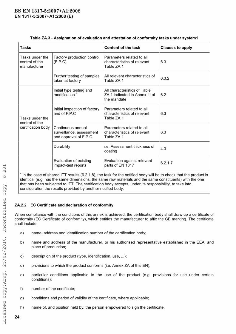
Table ZA.3 - Assignation of evaluation and attestation of conformity tasks under system1
Tasks Content of the task Clauses to apply
Factory production control (F.P.C)
Parameters related to all characteristics of relevant Table ZA.1
6.3Tasks under the control of the manufacturer
Further testing of samples taken at factory
All relevant characteristics of Table ZA.1 6.3.2
Initial type testing and modification a
All characteristics of Table ZA.1 indicated in Annex III of the mandate
6.2
Initial inspection of factory and of F.P.C
Parameters related to all characteristics of relevant Table ZA.1
6.3
Continuous annual surveillance, assessment and approval of F.P.C.
Parameters related to all characteristics of relevant Table ZA.1
6.3
Durability i.e. Assessment thickness of coating 4.3
Tasks under the control of the certification body
Evaluation of existing impact-test reports
Evaluation against relevant parts of EN 1317 6.2.1.7
a In the case of shared ITT results (6.2.1.8), the task for the notified body will be to check that the product is identical (e.g. has the same dimensions, the same raw materials and the same constituents) with the one that has been subjected to ITT. The certification body accepts, under its responsibility, to take into consideration the results provided by another notified body.
ZA.2.2 EC Certificate and declaration of conformity
When compliance with the conditions of this annex is achieved, the certification body shall draw up a certificate of conformity (EC Certificate of conformity), which entitles the manufacturer to affix the CE marking. The certificate shall include:
a) name, address and identification number of the certification body;
b) name and address of the manufacturer, or his authorised representative established in the EEA, and place of production;
c) description of the product (type, identification, use, ...);
d) provisions to which the product conforms (i.e. Annex ZA of this EN);
e) particular conditions applicable to the use of the product (e.g. provisions for use under certain conditions);
f) number of the certificate;
g) conditions and period of validity of the certificate, where applicable;
h) name of, and position held by, the person empowered to sign the certificate.
BS EN 1317-5:2007+A1:2008Licensed copy:Arup, 25/02/2010, Uncontrolled Copy, © BSI
EN 1317-5:2007+A1:2008 (E)
25
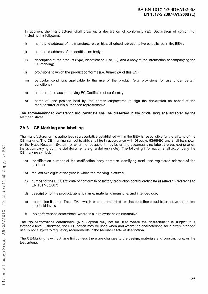
In addition, the manufacturer shall draw up a declaration of conformity (EC Declaration of conformity) including the following:
i) name and address of the manufacturer, or his authorised representative established in the EEA ;
j) name and address of the certification body;
k) description of the product (type, identification, use, ...), and a copy of the information accompanying the CE marking;
l) provisions to which the product conforms (i.e. Annex ZA of this EN);
m) particular conditions applicable to the use of the product (e.g. provisions for use under certain conditions);
n) number of the accompanying EC Certificate of conformity;
o) name of, and position held by, the person empowered to sign the declaration on behalf of the manufacturer or his authorised representative.
The above-mentioned declaration and certificate shall be presented in the official language accepted by the Member States.
ZA.3 CE Marking and labelling
The manufacturer or his authorised representative established within the EEA is responsible for the affixing of the CE marking. The CE marking symbol to affix shall be in accordance with Directive 93/68/EC and shall be shown on the Road Restraint System (or when not possible it may be on the accompanying label, the packaging or on the accompanying commercial documents e.g. a delivery note). The following information shall accompany the CE marking symbol:
a) identification number of the certification body name or identifying mark and registered address of the producer;
b) the last two digits of the year in which the marking is affixed;
c) number of the EC Certificate of conformity or factory production control certificate (if relevant) reference to EN 1317-5:2007;
d) description of the product: generic name, material, dimensions, and intended use;
e) information listed in Table ZA.1 which is to be presented as classes either equal to or above the stated threshold levels;
f) “no performance determined” where this is relevant as an alternative.
The “no performance determined” (NPD) option may not be used where the characteristic is subject to a threshold level. Otherwise, the NPD option may be used when and where the characteristic, for a given intended use, is not subject to regulatory requirements in the Member State of destination.
The CE-Marking is without time limit unless there are changes to the design, materials and constructions, or the test criteria.
BS EN 1317-5:2007+A1:2008Licensed copy:Arup, 25/02/2010, Uncontrolled Copy, © BSI

EN 1317-5:2007+A1:2008 (E)
26
01234
CE conformity marking, consisting of the “CE”-symbol given in Directive
93/68/EEC.
Identification number of the certification body (where relevant)
AnyCo Ltd, PO Box 21, B-1050
07
01234-CPD-00234
Name or identifying mark and registered address of the producer
Last two digits of the year in which the marking was affixed
Certificate number (where relevant)
EN 1317-5:2007
Product Conicbarrier, type C (doc. 334; May 2002), two sided median safety barrier to be used in
circulation areas
Performance under impact: a) Containment level: H1 and H2
b) Impact severity: A
c) Working Width: H1 = 1,1 m (W4)
H2 = 1,9 m (W6)
d) Dynamic deflection: H1 = 0,5 m
H2 = 1,3 m
Durability:S 235 JR G2 galvanized in accordance with EN ISO 1461
Dangerous substance:NPD
No. of European Standard
Description of product
and
information on regulated characteristics
Figure ZA.1.a – Example CE marking information for safety barriers Information to be given on the product, label, packaging and/or commercial document
In addition to any specific information relating to dangerous substances shown above, the product should also be accompanied, when and where required and in the appropriate form, by documentation listing any other legislation on dangerous substances for which compliance is claimed, together with any information required by that legislation.
BS EN 1317-5:2007+A1:2008Licensed copy:Arup, 25/02/2010, Uncontrolled Copy, © BSI
EN 1317-5:2007+A1:2008 (E)
27
01234
CE conformity marking, consisting of the “CE”-symbol given in Directive
93/68/EEC.
Identification number of the certification body (where relevant)
AnyCo Ltd, PO Box 21, B-1050
07
01234-CPD-00234
Name or identifying mark and registered address of the producer
Last two digits of the year in which the marking was affixed
Certificate number (where relevant)
EN 1317-5:2007
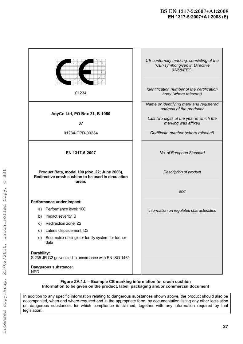
Product Beta, model 100 (doc. 22; June 2003), Redirective crash cushion to be used in circulation
areas
Performance under impact:
a) Performance level: 100
b) Impact severity: B
c) Redirection zone: Z2
d) Lateral displacement: D2
e) See matrix of single or family system for further data
Durability:S 235 JR G2 galvanized in accordance with EN ISO 1461
Dangerous substance:NPD
No. of European Standard
Description of product
and
information on regulated characteristics
Figure ZA.1.b – Example CE marking information for crash cushion Information to be given on the product, label, packaging and/or commercial document
In addition to any specific information relating to dangerous substances shown above, the product should also be accompanied, when and where required and in the appropriate form, by documentation listing any other legislation on dangerous substances for which compliance is claimed, together with any information required by that legislation.
BS EN 1317-5:2007+A1:2008Licensed copy:Arup, 25/02/2010, Uncontrolled Copy, © BSI
EN 1317-5:2007+A1:2008 (E)
28
01234
CE conformity marking, consisting of the “CE”-symbol given in Directive
93/68/EEC.
Identification number of the certification body (where relevant)
AnyCo Ltd, PO Box 21, B-1050
07
01234-CPD-00234
Name or identifying mark and registered address of the producer
Last two digits of the year in which the marking was affixed
Certificate number (where relevant)
EN 1317-5:2007
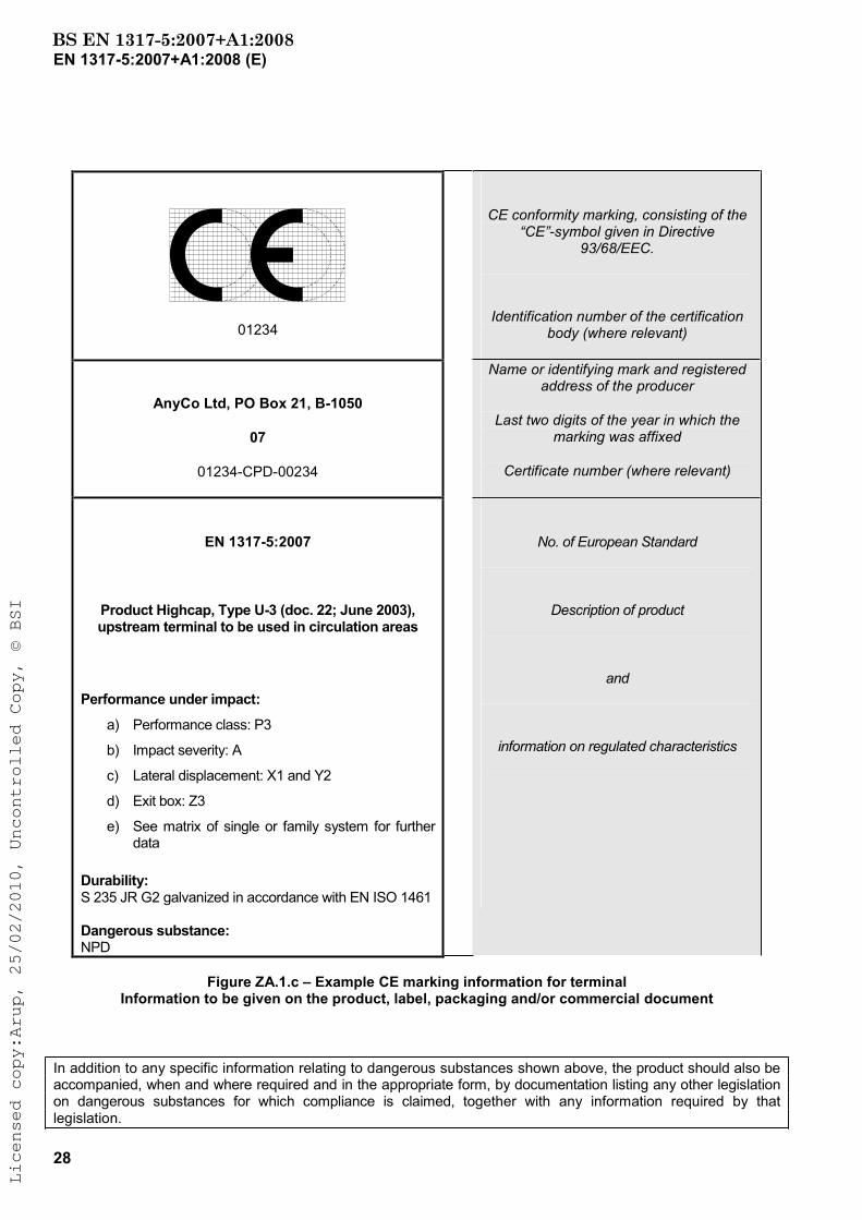
Product Highcap, Type U-3 (doc. 22; June 2003), upstream terminal to be used in circulation areas
Performance under impact:
a) Performance class: P3
b) Impact severity: A
c) Lateral displacement: X1 and Y2
d) Exit box: Z3
e) See matrix of single or family system for further data
Durability:S 235 JR G2 galvanized in accordance with EN ISO 1461
Dangerous substance:NPD
No. of European Standard
Description of product
and
information on regulated characteristics
Figure ZA.1.c – Example CE marking information for terminal Information to be given on the product, label, packaging and/or commercial document
In addition to any specific information relating to dangerous substances shown above, the product should also be accompanied, when and where required and in the appropriate form, by documentation listing any other legislation on dangerous substances for which compliance is claimed, together with any information required by that legislation.
BS EN 1317-5:2007+A1:2008Licensed copy:Arup, 25/02/2010, Uncontrolled Copy, © BSI

EN 1317-5:2007+A1:2008 (E)
29
01234
CE conformity marking, consisting of the “CE”-symbol given in Directive
93/68/EEC.
Identification number of the certification body (where relevant)
AnyCo Ltd, PO Box 21, B-1050
07
01234-CPD-00234
Name or identifying mark and registered address of the producer
Last two digits of the year in which the marking was affixed
Certificate number (where relevant)
EN 1317-5:2007
Product Transuniversal, Type 04 (doc. 765; June 2004), transition H1 to H2 to be used in circulation
areas
Performance under impact:
a) Containment level: H1
b) Impact severity: B
c) Working width: W3
d) Dynamic deflection: 0,9 m
Durability:S 235 JR G2 galvanized in accordance with EN ISO 1461
Dangerous substance:NPD
No. of European Standard
Description of product
and
information on regulated characteristics
Figure ZA.1.d – Example CE marking information for transition Information to be given on the product, label, packaging and/or commercial document
In addition to any specific information relating to dangerous substances shown above, the product should also be accompanied, when and where required and in the appropriate form, by documentation listing any other legislation on dangerous substances for which compliance is claimed, together with any information required by that legislation.
BS EN 1317-5:2007+A1:2008Licensed copy:Arup, 25/02/2010, Uncontrolled Copy, © BSI
EN 1317-5:2007+A1:2008 (E)
30
01234
CE conformity marking, consisting of the “CE”-symbol given in Directive
93/68/EEC.
Identification number of the certification body (where relevant)
AnyCo Ltd, PO Box 21, B-1050
07
01234-CPD-00234
Name or identifying mark and registered address of the producer
Last two digits of the year in which the marking was affixed
Certificate number (where relevant)
EN 1317-5:2007
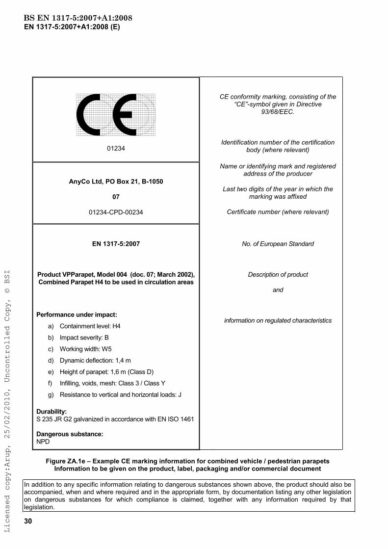
Product VPParapet, Model 004 (doc. 07; March 2002), Combined Parapet H4 to be used in circulation areas
Performance under impact:
a) Containment level: H4
b) Impact severity: B
c) Working width: W5
d) Dynamic deflection: 1,4 m
e) Height of parapet: 1,6 m (Class D)
f) Infilling, voids, mesh: Class 3 / Class Y
g) Resistance to vertical and horizontal loads: J
Durability:S 235 JR G2 galvanized in accordance with EN ISO 1461
Dangerous substance:NPD
No. of European Standard
Description of product
and
information on regulated characteristics
Figure ZA.1e – Example CE marking information for combined vehicle / pedestrian parapets Information to be given on the product, label, packaging and/or commercial document
In addition to any specific information relating to dangerous substances shown above, the product should also be accompanied, when and where required and in the appropriate form, by documentation listing any other legislation on dangerous substances for which compliance is claimed, together with any information required by that legislation.
BS EN 1317-5:2007+A1:2008Licensed copy:Arup, 25/02/2010, Uncontrolled Copy, © BSI
EN 1317-5:2007+A1:2008 (E)
31
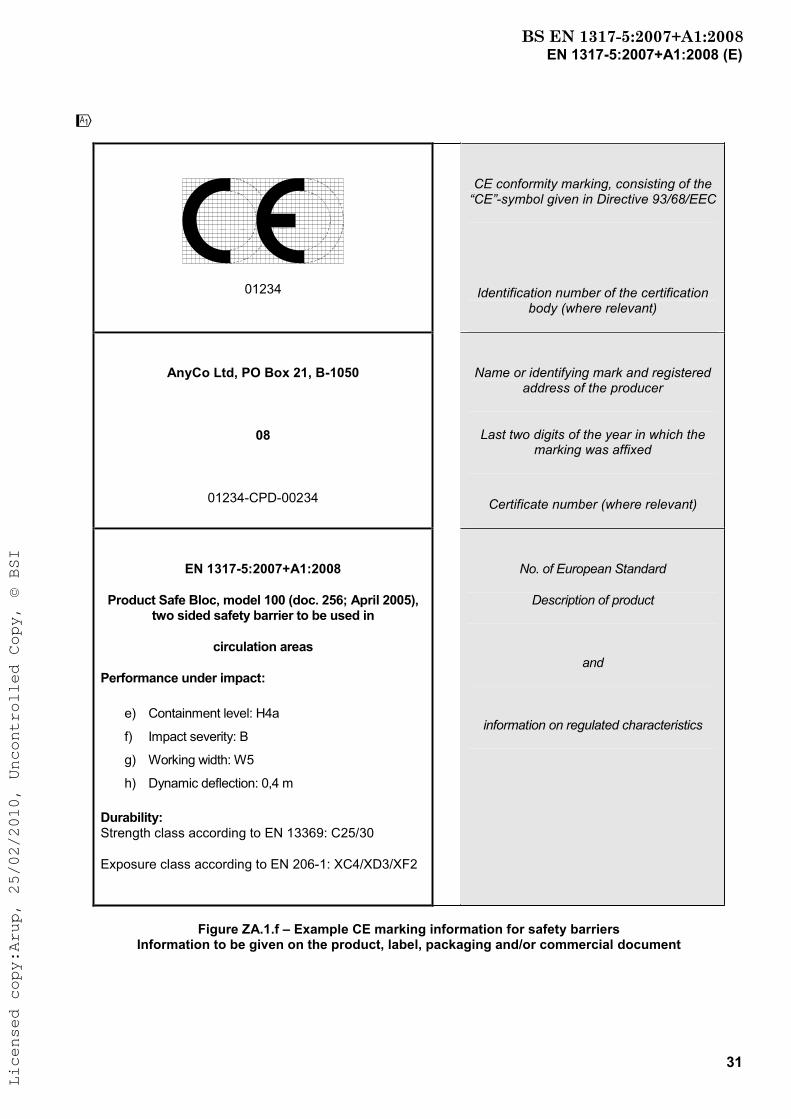
!
01234
CE conformity marking, consisting of the “CE”-symbol given in Directive 93/68/EEC
Identification number of the certification body (where relevant)
AnyCo Ltd, PO Box 21, B-1050
08
01234-CPD-00234
Name or identifying mark and registered address of the producer
Last two digits of the year in which the marking was affixed
Certificate number (where relevant)
EN 1317-5:2007+A1:2008
Product Safe Bloc, model 100 (doc. 256; April 2005), two sided safety barrier to be used in
circulation areas
Performance under impact:
e) Containment level: H4a
f) Impact severity: B
g) Working width: W5
h) Dynamic deflection: 0,4 m
Durability: Strength class according to EN 13369: C25/30
Exposure class according to EN 206-1: XC4/XD3/XF2
No. of European Standard
Description of product
and
information on regulated characteristics
Figure ZA.1.f – Example CE marking information for safety barriers Information to be given on the product, label, packaging and/or commercial document
BS EN 1317-5:2007+A1:2008Licensed copy:Arup, 25/02/2010, Uncontrolled Copy, © BSI

EN 1317-5:2007+A1:2008 (E)
32
In addition to any specific information relating to dangerous substances shown above, the product should also be accompanied, when and where required and in the appropriate form, by documentation listing any other legislation on dangerous substances for which compliance is claimed, together with any information required by that legislation.
"
BS EN 1317-5:2007+A1:2008Licensed copy:Arup, 25/02/2010, Uncontrolled Copy, © BSI
EN 1317-5:2007+A1:2008 (E)
33
Bibliography
[1] EN 1991-2, Eurocode 1: Actions on structures - Part 2: Traffic loads on bridges
BS EN 1317-5:2007+A1:2008Licensed copy:Arup, 25/02/2010, Uncontrolled Copy, © BSI

BS EN 1317-5:2007 +A1:2008
BSI Group Headquarters389 Chiswick High Road,London W4 4AL, UKTel +44 (0)20 8996 9001Fax +44 (0)20 8996 7001www.bsigroup.com/standards
British Standards Institution (BSI)BSI is the independent national body responsible for preparing British Standards. It presents the UK view on standards in Europe and at the international level. It is incorporated by Royal Charter.
Revisions
British Standards are updated by amendment or revision. Users of British Standards should make sure that they possess the latest amendments or editions.It is the constant aim of BSI to improve the quality of our products and services. We would be grateful if anyone finding an inaccuracy or ambiguity while using this British Standard would inform the Secretary of the technical committee responsible, the identity of which can be found on the inside front cover. Tel: +44 (0)20 8996 9000 Fax: +44 (0)20 8996 7400BSI offers members an individual updating service called PLUS which ensures that subscribers automatically receive the latest editions of standards.
Buying standards
Orders for all BSI, international and foreign standards publications should be addressed to Customer Services. Tel: +44 (0)20 8996 9001 Fax: +44 (0)20 8996 7001 Email: [email protected] may also buy directly using a debit/credit card from the BSI Shop on the Website http://www.bsigroup.com/shop.In response to orders for international standards, it is BSI policy to supply the BSI implementation of those that have been published as British Standards,unless otherwise requested.
Information on standards
BSI provides a wide range of information on national, European and international standards through its Library and its Technical Help to Exporters Service. Various BSI electronic information services are also available which give details on all its products and services. Contact the Information Centre. Tel: +44 (0)20 8996 7111 Fax: +44 (0)20 8996 7048 Email: [email protected] members of BSI are kept up to date with standards developments and receive substantial discounts on the purchase price of standards. For details of these and other benefits contact Membership Administration. Tel: +44 (0)20 8996 7002 Fax: +44 (0)20 8996 7001 Email: [email protected] regarding online access to British Standards via British Standards Online can be found at http://www.bsigroup.com/BSOL.Further information about BSI is available on the BSI website at http://www.bsigroup.com.
Copyright
Copyright subsists in all BSI publications. BSI also holds the copyright, in the UK, of the publications of the international standardization bodies. Except as permitted under the Copyright, Designs and Patents Act 1988 no extract may be reproduced, stored in a retrieval system or transmitted in any form or by any means – electronic, photocopying, recording or otherwise – without prior written permission from BSI. This does not preclude the free use, in the course of implementing the standard, of necessary details such as symbols, and size, type or grade designations. If these details are to be used for any other purpose than implementation then the prior written permission of BSI must be obtained. Details and advice can be obtained from the Copyright & Licensing Manager. Tel: +44 (0)20 8996 7070 Email: [email protected]
Licensed copy:Arup, 25/02/2010, Uncontrolled Copy, © BSI