aqua matic modular 450-1800
TRANSCRIPT

Aqua Matic Modular 450-1800
Owner’s ManualInitial Release - 1 December 2008
Manual PN B651140002 | Revision: 0 / /1
SRC Aqua Matic 450-1
SRC Aqua Matic 700-1
SRC Aqua Matic 900-1
SRC Aqua Matic 900-2
SRC Aqua Matic 1400-2
SRC Aqua Matic 1800-2
FOR DECEMBER 2008 MODELS


Aqua Matic Modular 450-1800 Owner’s Manual


Aqua Matic Modular 450-1800
Page i
PREFACEThank you for your purchase of a Sea Recovery Aqua Matic Reverse Osmosis Desalination System. This manual contains instructions for the installation, operation, maintenance, and repair of the Sea Recovery Desalination System. This information is provided to ensure extended life and safe operation of your Sea Recovery system.Please read this manual thoroughly before installation or operation, and keep it for future reference. A better understanding of the system ensures optimum performance and longer service life.Sea Recovery’s Reverse Osmosis Desalination Systems are designed and engineered to function as a complete working unit. Generally speaking, the performance of each component within the System is dependent on the component prior to it and governs the performance of all components after it. Proper performance of the system is thus dependent upon proper operation of every single component within the system.The intent of this manual is to allow the operator to become familiar with each component within the Sea Recovery system. By understanding the function, importance, and normal operation of each component within each subsystem of the unit, the operator can readily diagnose minor problems, which if detected early are usually easily corrected. However, if left unattended, a problem in one component eventually affects the rest of the system and leads to further repairs.The manual is divided into sections that address different subject matter. Each section should be reviewed before operating the Reverse Osmosis Desalination system.The major documented cause of failures and problems are from the use of third party, non Sea Recovery, parts, from improper installation, and from improper operation:The use of third party, non Sea Recovery, consumable, spares, and assemblies will damage the Sea Recovery system and/or specific components within the system. Do not use parts, components from any source other than Sea Recovery. Use of third party, non Sea Recovery, components will void any and all warranty of the system and/or void the effected component within the system.Sea Recovery maintains inventory for immediate shipment and our Service Dealers throughout the world maintain stock of Sea Recovery parts. Always insist on Sea Recovery supplied parts for your system in order to avoid failures, eliminate problems, and maintain your Sea Recovery Warranty.Follow the Installation and Operation Instructions in this manual.From time to time, Sea Recovery may make programming changes to the Control Logic.Other physical production changes may also be made from time to time and are tracked by Sea Recovery through the System Serial Number.
Troubleshooting and repair method results can vary depending on the information that is displayed at the SYSTEM INFORMATION screen.
• SERIAL NUMBER helps us to determine the latest physical version and configuration of your system which is necessary to ensure that we provide you with the correct information or parts.
• TYPE tells us the production capacity of your system which gives us a bench mark in diagnosing product water flow and pressure concerns.
• TIME RUNNING assists us in diagnosing abnormalities that can occur at given operational time intervals such as required pump maintenance, or R.O. membrane element condition.
• VERSION allows us to determine the specific sequential operation of the system based on the version of the programmed control logic.
When requesting assistance from Sea Recovery or Sea Recovery’s service dealers, always:
PROVIDE ALL INFORMATION DISPLAYED AT THE SYSTEM INFORMATION SCREEN.
Aqua Matic Modular 450-1800
Page ii
COPYRIGHT NOTIFICATIONCopyright 2008-2009® Sea Recovery Corporation. All content included within this manual, such as text, graphics, logos, and images, is the property of Sea Recovery Corporation and protected by U.S. and international copyright laws. The compilation (meaning the preparation, collection, arrangement, and assembly) of all content within this manual is the exclusive property of Sea Recovery Corporation and protected by U.S. and international copyright laws. All software used in the design and manufacture of the Sea Recovery Reverse Osmosis Desalination System is the property of Sea Recovery Corporation and protected by U.S. and international copyright laws. All computer and logic programming used in the design and manufacture of the Sea Recovery Reverse Osmosis Desalination System the property of Sea Recovery Corporation and protected by U.S. and international copyright laws.The content of this manual and the software, programming, and graphic designs used in the design and manufacture of the Sea Recovery Reverse Osmosis Desalination System is for the purpose of operation, maintaining, and repair of the Sea Recovery Reverse Osmosis Desalination System. Any other use, including the reproduction, modification, distribution, transmission, republication, display, or performance, of the content within this manual is strictly prohibited.
TERMS AND CONDITIONSThe use of this manual acknowledges acceptance of the terms and conditions provided herewith and the agreement to comply with all applicable laws and regulations pertaining to the use of this manual.In addition, the use of this manual forms an agreement that Sea Recovery’s trademarked name or Sea Recovery’s trademarked logo mark are not to be used in any form or manner except with Sea Recovery Corporation’s written permission. Sea Recovery Corporation holds all rights to its copyrights and trademarks, and to the material contained in this manual. Any use of such requires the written permission from Sea Recovery Corporation.
PATENT INFORMATIONCertain aspects of the Sea Recovery Reverse Osmosis Desalination System are protected by U.S. and International Patent Laws.
NOTICE OF LIABILITYThe information contained in the manual is distributed on an “As is” basis, without warranty. While every effort has been taken in the preparation of this manual, Sea Recovery Corp. shall not be held liable with respect to any liability, loss, or damage caused by the instructions contained in this manual. The information contained in this manual is subject to change without notice.
TRADEMARKSThe Sea Recovery® logo mark is a U.S. Registered Trademark and belongs to Sea Recovery Corporation with all rights reserved. Sea Recovery® is a US Registered trademark of Sea Recovery Corporation. Aqua Matic™ is a trademark of Sea Recovery Corp.

Aqua Matic Modular 450-1800
Page i
REVISION HISTORY
Rev. Date Affected Pages Description
Ø 1 December 2008 - Initial Release of the 2008 Models.
1 9/23/09 Pg.4-11 & FoldOut Revised Electrical Diagrams
2 11/18/09 - General Re-formatting
3 11/23/09 Pg. 5-2 Multi Media Installation Instructions revision
4 6/23/10 Section 10 Updated Parts / Added NMEA kit
5. 6/23/10 Pg. 2-1, 2-12, & 2-15 AQM modular with new GP pump
6. 6/23/10 Cover New AQM modular with plunger pump
7 5-30-13 Parts View Added HP 75, and Soft Start
8 5-30-13 Electrical & Certificates New Diagrams, New Certificates
Aqua Matic Modular 450-1800
Page iv
TABLE OF CONTENTS
1 INTRODUCTION 1-11.1 PURPOSE 1-11.2 SAFETY IN GENERAL 1-11.3 USING THIS MANUAL 1-11.4 TERM USED 1-11.5 REFERENCES 1-11.6 SAFETY NOTES 1-11.7 GRAPHICS 1-11.8 GLOSSARY 1-1
2 SYSTEM DESCRIPTION 2-12.1 MODELS 2-12.2 SPECIFICATIONS 2-12.3 COMPLIANCE 2-12.4 WARRANTY 2-12.5 REGISTRATION 2-12.6 PACKING LIST 2-12.7 COMPONENT DIMENSIONS 2-12.8 DAILY SYSTEM READING 2-12.9 CHEMICAL SAFETY 2-12.10 TEMPERATURE & PRESSURE EFFECTS 2-1
3 PRE-INSTALLATION NOTES 3-13.1 PRECAUTIONS 3-13.2 SPECIAL CONSIDERATIONS 3-13.3 DISTANCE BETWEEN COMPONENTS 3-23.5 COMPONENTS SUPPLIED BY INSTALLER 3-23.6 PIPING AND INTERCONNECT DIAGRAMS 3-33.7 EXPLANATION OF PRESSURE TRANSDUCERS 3-163.8 RO MEMBRANE ELEMENT NOTES 3-173.9 COMPONENT DESCRIPTIONS 3-17
4 ELECTRICAL INFORMATION 4-14.1 ELECTRICAL REQUIREMENTS AND INFORMATION 4-14.2. ELECTRICAL MOTOR SPECIFICATIONS 4-24.3. RECOMMENDED CIRCUIT BREAKER 4-24.4. RECOMMENDED POWER WIRE SIZE 4-34.5. WIRE INSERTION TO TERMINAL STRIPS 4-44.6. WIRE SIZE REFERENCES 4-44.7. MODULAR MODEL ELECTRICAL INFORMATION 4-64.8 MODULAR MODEL WIRING DIAGRAMS 4-11
5 INSTALLATION REQUIREMENTS 5-15.1 SYSTEM CONTROL BOX 5-15.2 COMPONENTS 5-1

Aqua Matic Modular 450-1800
Page v
5.3 INTERCONNECTING COMPONENTS 5-55.4 WATER TANK 5-65.5 REMOTE TOUCH SCREEN 5-65.6 ELECTRICAL CONNECTIONS 5-65.7 LAND FEED WATER PICK-UP 5-65.8 UV STERILIZER INSTALLATION 5-8
6 COMMISSIONING 6-16.1 CHECK INSTALLATION 6-16.2 CHECK R.O. MEMBRANE 6-16.3. SETUP CONTROLLER 6-16.4 CHECK SYSTEM MANUALLY 6-26.5 OPERATION NOTES 6-36.6 INITIAL STARTUP 6-4
6.6.1. POSITION SYSTEM VALVES 6-4
6.6.2. APPLY POWER TO THE SYSTEM 6-5
6.6.3. START THE SYSTEM 6-5
6.6.4. LOG SYSTEM READINGS 6-6
6.6.5. SHUTDOWN THE SYSTEM 6-6
6.7 WARNINGS AND CAUTIONS 6-6
7 OPERATION 7-17.1 DAILY OPERATION 7-3
7.1.1 POSITION VALVES 7-3
7.1.2 APPLY POWER TO THE SYSTEM 7-3
7.1.3 START THE SYSTEM 7-3
7.1.5. LOG SYSTEM READINGS 7-4
7.1.6. SHUTDOWN THE SYSTEM 7-4
7.2 SYSTEM STORAGE AND CLEANING 7-47.3 SHORT-TERM SHUTDOWN 7-87.4 LONG TERM SHUTDOWN 7-87.5 WINTERIZING PROCEDURE 7-97.6 R.O. MEMBRANE CLEANING 7-9
8 MAINTENANCE AND REPAIR 8-18.1 WEEKLY QUICK CHECK 8-28.2 OPERATOR MAINTENANCE INTERVALS 8-28.3 INDIVIDUAL COMPONENT MAINTENANCE AND REPAIR 8-28.4 UV STERILIZER MAINTENANCE 8-18
9 TROUBLESHOOTING 9-19.1 ALARM AND ERROR SCREENS 9-19.2 TROUBLESHOOTING COMPONENTS 9-29.3 ELECTRICAL TROUBLESHOOTING 9-18
Aqua Matic Modular 450-1800
Page vi
10 EXPLODED PARTS VIEW 10-110.1. WHEN ORDERING 10-110.3 AVAILABLE TUBES AND FITTINGS 10-210.4 INSTALLATION KIT B001990001 10-510.5 MAJOR PARTS 10-6
1. SEA STRAINER ASSY 3/4-B B006080002 10-6
2. BOOSTER PUMP ASSY N200 50/60/1 B016120001 10-7
3. BOOSTER PUMP ASSY N200 50/60/3 B016120002 10-8
4. BOOSTER PUMP HEAD N200 1221515772 10-9
5. MEDIA FILTER ASSY -4 HS/AW/UW B071080002 10-10
6. MULTI MEDIA FILTER PLUMBING ASSY B075000001 10-12
7. PLANKTON FILTER ASSY-SINGLE B008800001 10-13
8. PLANKTON FILTER ASSY-DOUBLE B008800002 10-14
9. PREFILTER DUAL AQM II B108140001 10-16
10. COMMERCIAL PREFILTER ASSY 32.5 SQ FT SRC AQM B109120001 10-18
11. OIL / WATER SEPARATOR ASSY SRC 32.5 SQ FT B111120001 10-19
12. HP PUMP MOTOR ASSY, 1 PHASE B156150001 (Optional) 10-20
13. HP PUMP MOTOR ASSY 3 PHASE B156150002 (Optional) 10-21
14. HP PUMP/MOTOR ASSY PGR 110/220/1 - B156930003 (Standard) 10-22
15. HP PUMP/MOTOR PLGR 110/220/60/1 - B156930006 (Standard) 10-23
16. HP PUMP/MOTOR PLGR 220/60/3 - B156150007 (Standard) 10-24
17. HP PUMP ASSY-12180513CO (Standard) 10-26
18. HP HOSE ASSEMBLY 10-28
19. MEMBRANE RACK 450-1 - B198000032 10-29
20. MEMBRANE RACK 700-1 - B198000033 10-30
21. MEMBRANE RACK 900-1 - B198000034 10-31
22. MEMBRANE RACK 900-2 - B198000035 10-32
23. MEMBRANE RACK 1400-2 - B198000036 10-33
24. MEMBRANE RACK 1800-2 - B198000037 10-34
25. CONTROLLER BOX A15M 10-36
26. CONTROLLER CHASSIS 1 PH B619940001 10-37
27. CONTROLLER CHASSIS 3 PH B619940002 10-38
28. BACK PRESSURE REGULATOR ASSY B476160003 10-39
29. LP BACK PRESSURE PLATE ASSY B515150002 10-40
30. LP TRANSDUCER ASSY B147130002 10-41
31. PH NEUTRALIZER / CHARCOAL DUAL AQMC II / MOD B114140001 10-42
32. CLEAN AND RINSE KIT AQM B591120001 10-43
33. FRESH WATER FLUSH (.50 INCH) B598000008 10-44
34. UV STERILIZER 12VDC 2GPM B5262000CV 10-46
35. SOFT START ASSY B596800006 10-47
36. REMOTE KIT DISPLAY 80FT STD AQMII B610140008 10-48
37. NMEA 2000 ENABLED B610140004 10-49
11 FOLDOUT 11-1
Introduction
Aqua Matic Modular 450-1800
Section 1 - INTRODUCTION

Intro
duct
ion
Aqua Matic Modular 450-1800
Page 1-1
Introduction
1.6 SAFETY NOTES
Safety issues that require users attention are highlight through out this manual as follows.
WARNING: A Warning note provides critical information users must comply within order to prevent the possibility of injuries and/or death.
CAUTION: A Caution note provides important information users must know to prevent the possibility of damaging the device or equipment.
NOTE: A Note provides additional information users should know to properly and safely operate the equipment.
1.7 GRAPHICS
Graphics used are for reference and illustration purposes only, and may not represent the actual part or arrangement of parts in a customized system.
1.8 GLOSSARY
Following terms are helpful in becoming familiar with the Sea Recovery Reverse Osmosis System.
BOUNDARY LAYER / CONCENTRATION POLARIZATION
When water permeates through the membrane, nearly all the salt is left behind in the brine channel. In any dynamic hydraulic system, the fluid adjacent to the wall of the vessel is moving relatively slow. Even though the main body of the stream is turbulent, a thin film adjacent to the wall (membrane) is laminar. This thin film is called the boundary layer.
At the boundary layer the salts are saturated and can readily adhere to and pack into the R.O. membrane element surface if the Feed Water Flow is insufficient. For this reason it is important to maintain sufficient Feed Water flow, to prevent Concentration Polarization, through the R.O. membrane element.
BRINE VELOCITY
The brine flow over the membrane surface is very important to both product water quality and quantity. At low flows, concentration polarization occurs, causing the water quality to decline.
1 INTRODUCTION
1.1 PURPOSE
This manual is intended for Sea Recovery’s system technicians, technical support, and training personnel. This manual contains technical information & instructions for the installation, operation, maintenance, and troubleshooting of the Sea Recovery Desalination System.
1.2 SAFETY IN GENERAL
Anyone responsible for the installation, operation, and maintenance of the Sea Recovery Desalination System must read this manual thoroughly and comply with the instructions, guidelines, and safety requirements at all times.
1.3 USING THIS MANUAL
Reading this manual in its entirety will help users to become familiar with each component within the system. By understanding the function, importance, and normal operation of each component, users can readily operate and diagnose problems.
Aside from this section, this manual is divided into ten majors sections.
• Section 2: System Description
• Section 3: Pre-installation Notes
• Section 4: Electrical Information
• Section 5: Installation Requirements
• Section 6: Commissioning
• Section 7: Operation
• Section 8: Maintenance & Repair
• Section 9: Troubleshooting
• Section 10: Exploded Parts View
• Section 11: Foldouts
Each section should be reviewed in the order provided before performing any system operations.
1.4 TERM USED
The term System refers to Aqua Matic System in general and will be used throughout this manual.
1.5 REFERENCES
All references in this manual refers to other sections within this manual unless specifically defined.
Aqua Matic Modular 450-1800
Page 1-2
Intro
duct
ion SPIRAL-WOUND MEMBRANE
The spiral-wound membrane consists of multiple membrane envelopes each formed by enclosing a channelized product water carrying material between two large flat membrane sheets. The membrane envelope is sealed on three edges with a special adhesive and attached with the adhesive to a small diameter pipe.
A polypropylene screen is used to form the feed water channel between the membrane envelopes. A wrap is applied to the membrane element to maintain the cylindrical configuration. The center tube is also the permeate (product water) collecting channel. Several elements may be connected in series within a single or multiple pressure vessels).
WATER TEMPERATURE EFFECT
The product water flow through the membrane is significantly affected by the water temperature. At any given pressure this flow increases with increasing water temperature and is reduced at lower temperatures. The System over comes this factor by self adjusting the operating pressure to maintain a precise amount of Product Water Flow.
In addition to inferior product water quality, low brine flows can increase the precipitation of sparingly soluble salts which will foul the R.O. membrane element surface (concentration polarization). If this occurs, the product water flux (production) will decline.
The Feed Pump integrated design provide a relatively smooth and continual flow of Feed Water across and through the R.O. membrane element.
COMPACTION
Some densification of the membrane structure may take place while operating at elevated pressures, above 1000 PSI. The change is known as compaction and is accompanied by a reduction in the water permeation rate.
When the R.O. membrane element is subjected to elevated pressures beyond 1000 PSI the Product Water Channel becomes squeezed which results in restriction and in turn product water recovery reduction.
OSMOTIC PRESSURE
The transfer of the water from one side of the membrane to the other will continue until the head (pressure) is great enough to prevent any net transfer of the solvent (water) to the more concentrated (feed water) solution.
At equilibrium, the quantity of water passing in either direction is equal, and the head pressure is then defined as the ”Osmotic Pressure” of the solution having that particular concentration of dissolved solids.
PRESSURE
The operating pressure has a direct affect on product water quality and quantity. Both factors will increase as the system pressure increases (higher quantity and higher quality within design limits).
The system must be operated at the lowest pressure required to achieve the designed product water flow rate. This parameter also minimizes compaction, which proceeds at a faster rate at higher pressures as well as at higher temperatures.
The System self adjusts its operating pressure to maintain a precise amount of Product Water Flow. However in so doing, at low temperatures and or high salinity feed water conditions the system will operate at higher than normal pressure in maintaining the specified amount of product water flow. This is normal, to be expected, and is due to the design characteristics of the system.

Description
Aqua Matic Modular 450-1800
Section 2 - SYSTEM DESCRIPTION

Desc
riptio
n

Aqua Matic Modular 450-1800
Page 2-1
Description
2 SYSTEM DESCRIPTION Since 1981, Sea Recovery Corporation has been producing water desalination systems for various applications to customers all around the world. Since then Sea Recovery has become one of the top leaders in advanced water desalination systems for leisure marine applications.
2.1 MODELS
Aqua Matic Modular series are available in six models.
SRC Aqua Matic 450-1•
SRC Aqua Matic 700-1•
SRC Aqua Matic 900-1•
SRC Aqua Matic 900-2•
SRC Aqua Matic 1400-2•
SRC Aqua Matic 1800-2•
2.2 SPECIFICATIONS
Refer to Page 2-2 for System Specification details.
2.3 COMPLIANCE
Sea Recovery’s Reverse Osmosis Desalination Systems are Type Accepted by the American Bureau of Shipping, ABS.
Sea Recovery’s Reverse Osmosis Desalination Systems comply with FCC § 15.105
Sea Recovery’s Reverse Osmosis Desalination Systems have been independently tested and determined to be in compliance with European CE (Conformité Européne).
Refer to Page 2-5 for compliance certificates.
2.4 WARRANTY
Sea Recovery guarantees its product, components, and replacement parts and recommends customers to use only Sea Recovery parts. The majority of RO system problems derive from premature failure of unauthorized third party replacement parts.
Using unauthorized third party components will lead to
higher operating costs and maintenance costs and labor. Most importantly, using unauthorized parts will void Sea Recovery Warranty.
Refer to Page 2-11 for Limited Warranty.
2.5 REGISTRATION
Sea Recovery recommends all customers to register their System immediately after delivery to ensure and guarantee product technical support and warranty.
2.6 PACKING LIST
For visual packing list and optional accessories refer to Page 2-13.
2.7 COMPONENT DIMENSIONS
Refer to Page 2-15 for system and component dimensions.
2.8 DAILY SYSTEM READING
Refer to Page 2-17 for daily system reading log sheet.
2.9 CHEMICAL SAFETY
Refer to Page 2-18 for chemical safety and first aid recommendations.
2.10 TEMPERATURE & PRESSURE EFFECTS
Refer to Page 2-20 for temperature and pressure effects on RO membrane performance.
Aqua Matic Modular 450-1800
Page 2-2
Desc
riptio
n
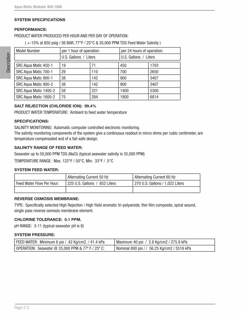
SYSTEM SPECIFICATIONS
PERFORMANCE:
PRODUCT WATER PRODUCED PER HOUR AND PER DAY OF OPERATION:
( +-15% at 850 psig / 56 BAR, 77°F / 25°C & 35,000 PPM TDS Feed Water Salinity )
Model Number per 1 hour of operation: per 24 hours of operation:
U.S. Gallons / Liters U.S. Gallons / Liters
SRC Aqua Matic 450-1 19 71 450 1703
SRC Aqua Matic 700-1 29 110 700 2650
SRC Aqua Matic 900-1 38 142 900 3407
SRC Aqua Matic 900-2 38 142 900 3407
SRC Aqua Matic 1400-2 58 221 1400 5300
SRC Aqua Matic 1800-2 75 284 1800 6814
SALT REJECTION (CHLORIDE ION): 99.4%
PRODUCT WATER TEMPERATURE: Ambient to feed water temperature
SPECIFICATIONS:
SALINITY MONITORING: Automatic computer controlled electronic monitoring. The salinity monitoring components of the system give a continuous readout in micro ohms per cubic centimeter, are temperature compensated and of a fail-safe design.
SALINITY RANGE OF FEED WATER:
Seawater up to 50,000 PPM TDS (NaCl) (typical seawater salinity is 35,000 PPM)
TEMPERATURE RANGE: Max. 122°F / 50°C, Min. 33°F / .5°C
SYSTEM FEED WATER:
Alternating Current 50 Hz Alternating Current 60 Hz
Feed Water Flow Per Hour: 225 U.S. Gallons / 852 Liters 270 U.S. Gallons / 1,022 Liters
REVERSE OSMOSIS MEMBRANE:
TYPE: Specifically selected High Rejection / High Yield aromatic tri-polyamide, thin film composite, spiral wound, single pass reverse osmosis membrane element.
CHLORINE TOLERANCE: 0.1 PPM.
pH RANGE: 3-11 (typical seawater pH is 8)
SYSTEM PRESSURE:
FEED WATER: Minimum 6 psi / .42 Kg/cm2. / 41.4 kPa Maximum 40 psi / 2.8 Kg/cm2 / 275.8 kPa
OPERATION: Seawater @ 35,000 PPM & 77º F / 25º C: Nominal 800 psi / / 56.25 Kg/cm2 / 5516 kPa

Aqua Matic Modular 450-1800
Page 2-3
Description
EXTERNAL INSTALLATION WATER CONNECTIONS:
Pipe sizes to be supplied by the installer for connection of the Sea Recovery supplied components
Aqua Matic
Feed Inlet: 3/4 in. (19 mm) MNPT Male National Pipe Thread U.S. Standard
Brine Discharge 3/4 in. (19 mm) MNPT Male National Pipe Thread U.S. Standard
Product 1/2 in. (12.7 mm) FNPT Female National Pipe Thread U.S. Standard
WEIGHT:
MODEL Modular Style
Aqua Matic 450-1 149 lbs / 68 kg
Aqua Matic 700-1 152 lbs / 69 kg
Aqua Matic 900-1 154 lbs / 70 kg
Aqua Matic 900-2 161 lbs / 73 kg
Aqua Matic 1400-2 167 lbs / 76 kg
Aqua Matic 1800-2 172 lbs / 78 kg
ELECTRICAL MOTOR SPECIFICATIONS:
(H.P. = Horse Power; RPM = Revolutions Per Minute; FLA = Full Load Amperes; LRA = Locked Rotor Amperes @ Start Up)
ALTERNATING CURRENT SYSTEMS:
Single Phase Alternating Current:
High Pressure Pump Motor Booster Pump Motor
VAC Hz H.P RPM FLA LRA H.P RPM FLA LRA
110 50 3 2850 23 89 .5 2850 7.4 20
220 50 3 2850 11.5 44 .5 2850 3.7 10
115 60 3 3450 25.4 86 .5 3450 9.4 20
230 60 3 3450 12.7 43 .5 3450 4.7 10
Three Phase Alternating Current:
High Pressure Pump Motor Booster Pump Motor
VAC Hz H.P RPM FLA LRA H.P RPM FLA LRA
220 50 2.5 2850 7.9 24.9 .5 2850 2.5 8.2
380 50 2.5 2850 4.6 14.4 .5 2850 1.5 4.7
230 60 3 3450 7.6 23.8 .5 3450 2.4 7.9
460 60 3 3450 3.8 11.9 .5 3450 1.2 3.9

Aqua Matic Modular 450-1800
Page 2-4
Desc
riptio
n
RECOMMENDED CIRCUIT BREAKER SUPPLYING POWER TO SYSTEM AMPERAGE RATING:
Operating Recommended
AC Voltage Phase Circuit Breaker
110 - 115 VAC Single 50 Ampere
220 - 230 VAC Single 25 Ampere
220 VAC Three 15 Ampere
380 VAC Three 10 Ampere
460 VAC Three 10 Ampere
RECOMMENDED POWER WIRE SIZE TO AQUA MATIC SYSTEM:
Operating Phase Maximum Recommended Minimum Wire Size for Length of run
Voltage Load
10 Ft / 3 meter 25 Ft / 8 meter 50 Ft / 15 meter
110-115 VAC Single 34.8 Ampere 10 AWG / 6 mm2 8 AWG / 10 mm2 8 AWG / 10 mm2
220-230 VAC Single 17.4 Ampere 12 AWG / 4 mm2 12 AWG / 4 mm2 12 AWG / 4 mm2
220-230 VAC Three 10.4 Ampere 14 AWG / 2.5 mm2 14 AWG / 2.5 mm2 14 AWG / 2.5 mm2
380 VAC Three 6.1 Ampere 14 AWG / 2.5 mm2 14 AWG / 2.5 mm2 14 AWG / 2.5 mm2
460 VAC Three 5 Ampere 14 AWG / 2.5 mm2 14 AWG / 2.5 mm2 14 AWG / 2.5 mm2
RECOMMENDED POWER WIRE SIZE TO AQUA MATIC BOOSTER PUMP:
Operating Phase Maximum Recommended Minimum Wire Size for Length of run
Voltage Load
10 Ft / 3 meter 25 Ft / 8 meter 50 Ft / 15 meter
110-115 VAC Single 9.4 Ampere 14 AWG / 2.5 mm2 14 AWG / 2.5 mm2 14 AWG / 2.5 mm2
220-230 VAC Single 4.7 Ampere 14 AWG / 2.5 mm2 14 AWG / 2.5 mm2 14 AWG / 2.5 mm2
220-230 VAC Three 2.5 Ampere 16 AWG / 1.5 mm2 16 AWG / 1.5 mm2 16 AWG / 1.5 mm2
380 VAC Three 1.5 Ampere 16 AWG / 1.5 mm2 16 AWG / 1.5 mm2 16 AWG / 1.5 mm2
460 VAC Three 1.2 Ampere 16 AWG / 1.5 mm2 16 AWG / 1.5 mm2 16 AWG / 1.5 mm2
RECOMMENDED POWER WIRE SIZE TO AQUA MATIC HIGH PRESSURE PUMP:
Operating Phase Maximum Recommended Minimum Wire Size for Length of run
Voltage Load
10 Ft / 3 meter 25 Ft / 8 meter 50 Ft / 15 meter
110-115 VAC Single 25.5 Ampere 12 AWG / 4 mm2 10 AWG / 6 mm2 10 AWG / 6 mm2
220-230 VAC Single 12.7 Ampere 14 AWG / 2.5 mm2 12 AWG / 4 mm2 12 AWG / 4 mm2
220-230 VAC Three 7.9 Ampere 14 AWG / 2.5 mm2 14 AWG / 2.5 mm2 14 AWG / 2.5 mm2
380 VAC Three 4.6 Ampere 14 AWG / 2.5 mm2 14 AWG / 2.5 mm2 14 AWG / 2.5 mm2
460 VAC Three 3.8 Ampere 14 AWG / 2.5 mm2 14 AWG / 2.5 mm2 14 AWG / 2.5 mm2

Certificate Number: 06-HS159834E-1-PDA
Confirmation of Product Type Approval 22/FEB/2011Please refer to the "Service Restrictions" shown below to determine if Unit Certification is required for this product.
This is to certify that, pursuant to the Rules of the American Bureau of Shipping (ABS), the manufacturer of thebelow listed product held a valid Manufacturing Assessment (MA) with expiration date of 19/MAY/2014. Thecontinued validity of the Manufacturing Assessment is dependent on completion of satisfactory audits as requiredby the ABS Rules.
And; a Product Design Assessment (PDA) valid until 22/NOV/2015 subject to continued compliance with the Rulesor standards used in the evaluation of the product.
The above entitle the product to be called Product Type Approved.
The Product Design Assessment is valid for products intended for use on ABS classed vessels, MODUs or facilitieswhich are in existence or under contract for construction on the date of the ABS Rules used to evaluate theProduct.
ABS makes no representations regarding Type Approval of the Product for use on vessels, MODUs or facilitiesbuilt after the date of the ABS Rules used for this evaluation.
Due to wide variety of specifications used in the products ABS has evaluated for Type Approval, it is part of ourcontract that; whether the standard is an ABS Rule or a non-ABS Rule, the Client has full responsibility forcontinued compliance with the standard.
SEA RECOVERY CORP.Model Name(s): Aqua Matic
Presented to:SEA RECOVERY CORP.19610 S. RANCHO WAYRANCHO DOMINGUEZUnited States
Intended Service: Marine & Offshore Application - Production of Fresh Water by Sea Desalination
Description: Reverse Osmosis Desalination Unit. See attached "pdf" product details
Ratings: Aqua Matic Compact: 19 GPH - 75 GPH Aqua Matic Modular: 19 GPH - 75 GPH
Service Restrictions: Unit Certification is not required for this product. If the manufacturer or purchaserrequest an ABS Certificate for compliance with a specification or standard, thespecification or standard, including inspection standards and tolerances, must beclearly defined.
Comments: 1) The use of PVC piping is limited to 35 psi for water application.
Notes / Documentation:Term of Validity: This Product Design Assessment (PDA) Certificate 06-HS159834E-1-PDA, dated
23/Nov/2010 remains valid until 22/Nov/2015 or until the Rules or specificationsused in the assessment are revised (whichever occurs first). This PDA is intendedfor a product to be installed on an ABS classed vessel, MODU or facility which is inexistence or under contract for construction on the date of the ABS Rules orspecifications used to evaluate the Product. Use of the Product on an ABS classedvessel, MODU or facility which is contracted after the validity date of the ABS Rulesand specifications used to evaluate the Product, will require re-evaluation of thePDA. Use of the Product for non ABS classed vessels, MODUs or facilities is to beto an agreement between the manufacturer and intended client.
ABS Rules: 2010 Steel Vessels Rules 1-1-4/7.7, 1-1-Appendix 3, 4-6-2/5.7
National Standards:
02/22/2011 1:36:27 PM Copyright 2001 American Bureau of Shipping. All rights reserved. Page 1 of 2
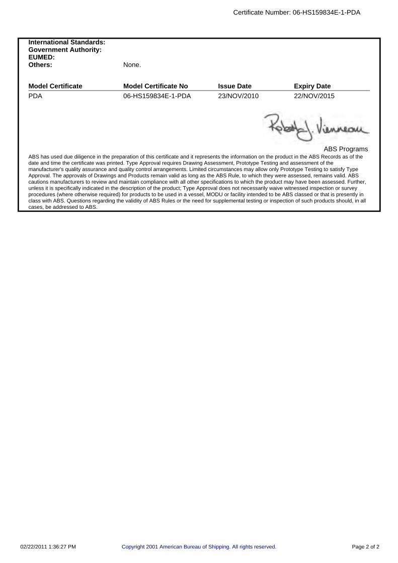
International Standards:Government Authority:EUMED:Others: None.
Model Certificate Model Certificate No Issue Date Expiry DatePDA 06-HS159834E-1-PDA 23/NOV/2010 22/NOV/2015
ABS ProgramsABS has used due diligence in the preparation of this certificate and it represents the information on the product in the ABS Records as of thedate and time the certificate was printed. Type Approval requires Drawing Assessment, Prototype Testing and assessment of themanufacturer's quality assurance and quality control arrangements. Limited circumstances may allow only Prototype Testing to satisfy TypeApproval. The approvals of Drawings and Products remain valid as long as the ABS Rule, to which they were assessed, remains valid. ABScautions manufacturers to review and maintain compliance with all other specifications to which the product may have been assessed. Further,unless it is specifically indicated in the description of the product; Type Approval does not necessarily waive witnessed inspection or surveyprocedures (where otherwise required) for products to be used in a vessel, MODU or facility intended to be ABS classed or that is presently inclass with ABS. Questions regarding the validity of ABS Rules or the need for supplemental testing or inspection of such products should, in allcases, be addressed to ABS.
Certificate Number: 06-HS159834E-1-PDA
02/22/2011 1:36:27 PM Copyright 2001 American Bureau of Shipping. All rights reserved. Page 2 of 2

DDee cc
ll aarr aa
tt ii oonn
oo ff CC
oo nnff oo
rr mmii tt yy
Man
ufa
ctu
rer’
s N
ame:
S
ea R
ecov
ery
Man
ufa
ctu
rer’
s A
dd
ress
: 19
610
Sou
th R
anch
o W
ay
Ran
cho
Dom
ingu
ez, C
A 9
022
0
U.S
.A.
SEA
RE
CO
VE
RY
dec
lare
s th
at t
he
follo
win
g m
odel
s
con
form
to
the
EN
550
11A
an
d E
N 5
00
82-
2 st
and
ards
:
Pro
du
ct S
eri
es:
M
od
el
Na
me
s:
Aqu
a M
atic
Ser
ies
Aqu
a M
atic
A
qua
Wh
isp
er S
erie
s A
qua
Wh
isp
er /
DX
A
qua
Wh
isp
er M
ini S
erie
s A
qua
Wh
isp
er M
ini
Ult
ra W
his
per
Ser
ies
Ult
ra W
his
per
C
oral
Sea
Ser
ies
Cor
al S
ea
Su
pp
lem
en
tary
In
form
ati
on
:
“Th
e p
rod
uct
com
pli
es w
ith
th
e
Req
uir
emen
ts o
f th
e E
MC
Dir
ecti
ve 8
9/3
36/E
EC
.”
Lis
a G
om
ez
Qu
ali
ty &
En
viro
nm
enta
l Ma
na
ger
M
anu
fact
ure
r’s
Con
tact
O
ffic
ial S
eal


Aqua Matic Modular 450-1800
Page 2-11
Description
LIMITED WARRANTY
Sea Recovery Aqua Matic 450 - 1800Sea Recovery warrants that the Sea Recovery Desalination System performs according to specifications for a period of twelve (12) months from the date of shipment. Sea Recovery’s liability under this warranty is limited to repair or replacement of the Aqua Matic Desalination System at Sea Recovery’s discretion. Under no circumstances is Sea Recovery liable for consequential damages arising out of or in any way connected with the failure of the system to perform as set forth herein. This limited warranty is in lieu of all other expressed or implied warranties, including those of merchantability and fitness for a particular purpose.Warranty Period starts from the date of original shipment by Sea Recovery, or with proof of purchase from the date of sale to the original retail purchaser:1. System and accessories: 1 (one) year2. Repairs made by Sea Recovery after the original warranty period has expired: 3 (three) monthsNormal reoccurring user maintenance listed below is not covered by this or any Sea Recovery limited warranty:1. Sea Strainer Element 3. Fuses 5. Instrument Calibration2. Cartridge Filter Elements 4. Centrifugal Pump Seal AssembliesThis or any Sea Recovery limited warranty does not cover installation components not supplied by Sea Recovery. Improper installation resulting in the Sea Recovery System or component failure or decline in performance is not covered by this or any Sea Recovery limited warranty.The Sea Recovery Reverse Osmosis Membrane Element is guaranteed to be cleanable for a minimum of one year from date of shipment, providing cleaning periods are adhered to, and fouling is acid soluble metal hydroxides and calcium carbonates or alkaline soluble organic, inorganic substances and microbiological slimes. The Sea Recovery R.O. Membrane Element is not guaranteed against iron fouling (rust), chemical or petroleum products attack, extreme temperatures [over 120° F (49° C) under 32° F (0° C)], drying out, or extreme pressures [over 1000 psig (69 bar )].In the event of a defect, a malfunction, or failure specifically covered by this warranty and during the warranty period, Sea Recovery will repair or replace, at its option, the product or component therein which upon examination by Sea Recovery appears to be defective.To obtain warranty service, the defective product or part must be returned to an authorized Sea Recovery Service Center or direct to Sea Recovery. An updated listing of Sea Recovery Factory Service Centers can be found on the Sea Recovery web site at http://www.searecovery.com. The purchaser must pay any transportation or labor expenses incurred in removing and returning the product to the service center or to Sea Recovery.The limited warranty does not extend to any system or system component which has been subjected to alteration, misuse, neglect, accident, improper installation, inadequate or improper repair or maintenance or subject to use in violation of instructions furnished by Sea Recovery, nor does the warranty extend to components on which the serial number has been removed, defaced, or changed.Sea Recovery reserves the right to make changes or improvements in its product, during subsequent production, without incurring the obligation to incorporate such changes or improvements on previously manufactured equipment.The implied warranties, which the law imposes on the sale of this product, are expressly LIMITED in duration to the time period above. Sea Recovery shall not be liable for damages, consequential or otherwise, resulting from the installation, use, and/or operation of this product or from the breach of this LIMITED WARRANTY.CAUTION: Use of non Sea Recovery supplied parts and accessories, including but not limited to, maintenance parts, pre-filter elements, cleaning and storage chemical, spare parts, replacement parts, system components, installation components and/or system accessories, shall void all warranty expressed or implied.
Sea Recovery Corp. PO Box 5288 Carson, CA 90745-5288 [email protected]
www.searecovery.com
Aqua Matic Modular 450-1800
Page 2-12
Desc
riptio
n
Some of the damages that may not be covered by the warranty include:
a) Use of non-authorized or misuse of authorized chemicals for storage will void any warranty.
b) Rust fouling of the R.O. Membrane Element is not covered under warranty.
c) Damage to the System caused by a blocked brine discharge or product line will not be covered by warranty.
d) High temperature will cause up to 40% flux loss (loss of production) of the R.O. membrane element(s). This damage is irreversible to the R.O. membrane element and not covered by warranty.
e) Freezing temperatures will cause mechanical damage to the System and R.O. membrane element due to the expansion of water as it freezes. This damage is irreversible and not covered by any warranty.
f) Damage caused by excessive vibration will not be covered under warranty.
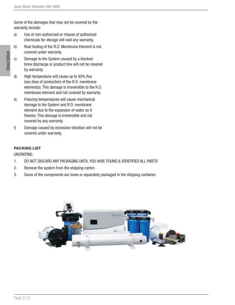
PACKING LIST
UNCRATING:
1. DO NOT DISCARD ANY PACKAGING UNTIL YOU HAVE FOUND & IDENTIFIED ALL PARTS!
2. Remove the system from the shipping carton.
3. Some of the components are loose or separately packaged in the shipping container.

Aqua Matic Modular 450-1800
Page 2-13
Description
Installation Kit B001140003
10
16
1715
4 7
8
20
3
19
9
2
21
6
ITEM PART NO DESCRIPTION QTY UM
1 061100043000 WASHER FLAT OS 1/4”SS 12.00 EACH
2 061172143016 SC HEX “A” 1/4 X 1 SS 12.00 EACH
3 05181432AA HOSE CLAMP 1/2” 4.00 EACH
4 05181434AA HOSE CLAMP 3/4” SS 22.00 EACH
5 061170628016 SC PHIL PAN “A” 10 X 1 SS 5.00 EACH
6 061080028000 WASHER FLAT #10 SS 5.00 EACH
7 2115031700 RUBBER MOUNT 90 LB AQM 4.00 EACH
8 061110049000 WASHER FENDER 5/16”SS 4.00 EACH
9 061172149036 SC HEX “A” 5/16 2 3/8 SS 4.00 EACH
10 B651140002 OWNERS MANUAL AQMMII 1.00 EACH
11 B645800001 MCC-1 ALKALINE CLEANER 1.00 EACH
12 B645800002 MCC-2 ACID CLEANER 1.00 EACH
13 0328066666 HOSE CLEAR BRAID 3/4” 50.00 FEET
14 0101013783 ELB90 3/4 FPT X 3/4 FPT PVC 1.00 EACH
15 0101653783 ADAP 3/4 MPT X 3/4 BARB PVC 3.00 EACH
16 0421051239 SEA STRAINER-3/4 BRONZE 1.00 EACH
17 0101073783 ELB90 3/4 MPT X 3/4 BARB PVC 2.00 EACH
18 0101423783 TEE 3/4 FT X 3/4 FT X 3/4 FT P 2.00 EACH
19 0101293483 RB 3/4 MT X 1/4 FT PVC 2.00 EACH
20 0204020869 ELB90 1/4 TUBE X 1/4 MPT PLAST 2.00 EACH
21 0312121969 TUBE 1/4 BLACK 20.00 FEET
22 0101652583 ADAP 1/2 MPT X 1/2 BARB PVC 1.00 EACH
23 0328065066 HOSE CLEAR BRAID 1/2” 50.00 FEET
24 0101012583 ELB90 1/2 FPT X 1/2 FPT PVC 1.00 EACH
23
13
1 5
14
18 22 24

Aqua Matic Modular 450-1800
Page 2-14
Desc
riptio
n
OPTIONAL ACCESSORIES

Aqua Matic Modular 450-1800
Page 2-15
Description
MODULAR UNIT DIMENSIONS
17" / 432 mm
7" / 178 mm
11" / 279 mm
17" / 483 mm20" / 508 mm
7" / 178 mm
Control Panel - Front
9.56
10.79 20.77
9.38

Aqua Matic Modular 450-1800
Page 2-16
Desc
riptio
n
COMPONENT DIMENSIONS
Sea Strainer Dual Pre-filter &
Dual Post-filterBooster Pump
Double R.O. Membrane Vessel Assembly
a.
b.
c.
a. 27 15/16” - 710mm: SRC Aqua Matic 450-1 & 900-2
b. 37 15/16” - 964mm: SRC Aqua Matic 700-1 & 1400-2
c. 46 15/16” - 1192mm: SRC Aqua Matic 900-1 & 1800-2
c.
b.
a.
Aqua Matic Modular 450-1800
Page 2-17
Description
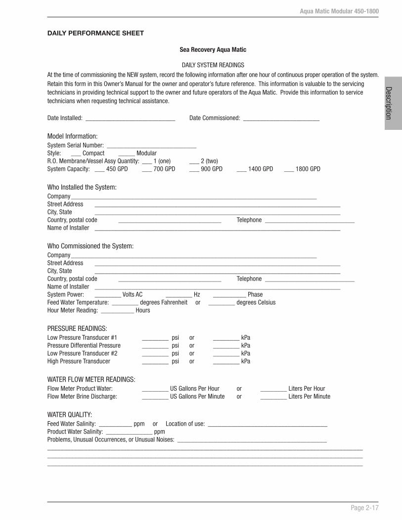
DAILY PERFORMANCE SHEET
Sea Recovery Aqua Matic
DAILY SYSTEM READINGS
At the time of commissioning the NEW system, record the following information after one hour of continuous proper operation of the system.Retain this form in this Owner’s Manual for the owner and operator’s future reference. This information is valuable to the servicing technicians in providing technical support to the owner and future operators of the Aqua Matic. Provide this information to service technicians when requesting technical assistance.
Date Installed: ___________________________ Date Commissioned: _______________________
Model Information:System Serial Number: ___________________________Style: ___ Compact _____ ModularR.O. Membrane/Vessel Assy Quantity: ___ 1 (one) ___ 2 (two)System Capacity: ___ 450 GPD ___ 700 GPD ___ 900 GPD ___ 1400 GPD ___ 1800 GPD
Who Installed the System:Company __________________________________________________________________________Street Address __________________________________________________________________________City, State __________________________________________________________________________Country, postal code _______________________________ Telephone ___________________________Name of Installer __________________________________________________________________________
Who Commissioned the System:Company __________________________________________________________________________Street Address __________________________________________________________________________City, State __________________________________________________________________________Country, postal code _______________________________ Telephone ___________________________Name of Installer __________________________________________________________________________System Power: ________ Volts AC ________ Hz __________ PhaseFeed Water Temperature: ________ degrees Fahrenheit or ________ degrees CelsiusHour Meter Reading: __________ Hours
PRESSURE READINGS:Low Pressure Transducer #1 ________ psi or ________ kPaPressure Differential Pressure ________ psi or ________ kPaLow Pressure Transducer #2 ________ psi or ________ kPaHigh Pressure Transducer ________ psi or ________ kPa
WATER FLOW METER READINGS:Flow Meter Product Water: ________ US Gallons Per Hour or ________ Liters Per HourFlow Meter Brine Discharge: ________ US Gallons Per Minute or ________ Liters Per Minute
WATER QUALITY:Feed Water Salinity: __________ ppm or Location of use: ____________________________________Product Water Salinity: ______________ ppmProblems, Unusual Occurrences, or Unusual Noises: __________________________________________________________________________________________________________________________________________________________________________________________________________________________________________________________________________________________________________________________________________
Aqua Matic Modular 450-1800
Page 2-18
Desc
riptio
n
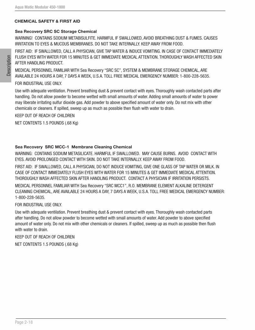
CHEMICAL SAFETY & FIRST AID
Sea Recovery SRC SC Storage Chemical
WARNING! CONTAINS SODIUM METABISULFITE. HARMFUL IF SWALLOWED, AVOID BREATHING DUST & FUMES. CAUSES IRRITATION TO EYES & MUCOUS MEMBRANES. DO NOT TAKE INTERNALLY. KEEP AWAY FROM FOOD.
FIRST AID: IF SWALLOWED, CALL A PHYSICIAN, GIVE TAP WATER & INDUCE VOMITING. IN CASE OF CONTACT IMMEDIATELY FLUSH EYES WITH WATER FOR 15 MINUTES & GET IMMEDIATE MEDICAL ATTENTION. THOROUGHLY WASH AFFECTED SKIN AFTER HANDLING PRODUCT.
MEDICAL PERSONNEL FAMILIAR WITH Sea Recovery “SRC SC”, SYSTEM & MEMBRANE STORAGE CHEMICAL, ARE AVAILABLE 24 HOURS A DAY, 7 DAYS A WEEK, U.S.A. TOLL FREE MEDICAL EMERGENCY NUMBER: 1-800-228-5635.
FOR INDUSTRIAL USE ONLY.
Use with adequate ventilation. Prevent breathing dust & prevent contact with eyes. Thoroughly wash contacted parts after handling. Do not allow powder to become wetted with small amounts of water. Adding small amounts of water to power may liberate irritating sulfur dioxide gas. Add powder to above specified amount of water only. Do not mix with other chemicals or cleaners. If spilled, sweep up as much as possible then flush with water to drain.
KEEP OUT OF REACH OF CHILDREN
NET CONTENTS 1.5 POUNDS (.68 Kg)
Sea Recovery SRC MCC-1 Membrane Cleaning Chemical
WARNING: CONTAINS SODIUM METASILICATE. HARMFUL IF SWALLOWED. MAY CAUSE BURNS. AVOID CONTACT WITH EYES. AVOID PROLONGED CONTACT WITH SKIN. DO NOT TAKE INTERNALLY. KEEP AWAY FROM FOOD.
FIRST AID: IF SWALLOWED, CALL A PHYSICIAN, DO NOT INDUCE VOMITING, GIVE ONE GLASS OF TAP WATER OR MILK. IN CASE OF CONTACT IMMEDIATELY FLUSH EYES WITH WATER FOR 15 MINUTES & GET IMMEDIATE MEDICAL ATTENTION. THOROUGHLY WASH AFFECTED SKIN AFTER HANDLING PRODUCT. CONTACT A PHYSICIAN IF IRRITATION PERSISTS.
MEDICAL PERSONNEL FAMILIAR WITH Sea Recovery “SRC MCC1”, R.O. MEMBRANE ELEMENT ALKALINE DETERGENT CLEANING CHEMICAL, ARE AVAILABLE 24 HOURS A DAY, 7 DAYS A WEEK, U.S.A. TOLL FREE MEDICAL EMERGENCY NUMBER: 1-800-228-5635.
FOR INDUSTRIAL USE ONLY.
Use with adequate ventilation. Prevent breathing dust & prevent contact with eyes. Thoroughly wash contacted parts after handling. Do not allow powder to become wetted with small amounts of water. Add powder to above specified amount of water only. Do not mix with other chemicals or cleaners. If spilled, sweep up as much as possible then flush with water to drain.
KEEP OUT OF REACH OF CHILDREN
NET CONTENTS 1.5 POUNDS (.68 Kg)

Aqua Matic Modular 450-1800
Page 2-19
Description
Sea Recovery SRC MCC-2 Membrane Cleaning Chemical
DANGER: CONTAINS SULFAMIC ACID. CAUSES BURNS, EYE & SKIN IRRITATION. HARMFUL IF SWALLOWED. AVOID BREATHING DUST. DO NOT TAKE INTERNALLY. KEEP AWAY FROM FOOD.
FIRST AID: IF SWALLOWED, CALL A PHYSICIAN, DO NOT INDUCE VOMITING, GIVE ONE GLASS OF TAP WATER OR MILK. IN CASE OF CONTACT IMMEDIATELY FLUSH EYES WITH WATER FOR 15 MINUTES & GET IMMEDIATE MEDICAL ATTENTION. THOROUGHLY WASH AFFECTED SKIN AFTER HANDLING PRODUCT. CONTACT A PHYSICIAN IF IRRITATION PERSISTS.
MEDICAL PERSONNEL FAMILIAR WITH Sea Recovery “SRC MCC2”, R.O. MEMBRANE ELEMENT ACID CLEANING CHEMICAL, ARE AVAILABLE 24 HOURS A DAY, 7 DAYS A WEEK, U.S.A. TOLL FREE MEDICAL EMERGENCY NUMBER: 1-800-228-5635.
FOR INDUSTRIAL USE ONLY.
DO NOT MIX WITH CHLORINATED SOLUTIONS OR COMPOUNDS. Use with adequate ventilation. Prevent breathing dust and prevent contact with eyes. Thoroughly wash contacted parts after handling. Do not allow powder to become wetted with small amounts of water. Add powder to above specified amount of water only. Do not mix with other chemicals or cleaners. If spilled, sweep up as much as possible then flush with water to drain.
KEEP OUT OF REACH OF CHILDREN
NET CONTENTS 1.5 POUNDS (.68 Kg)
Sea Recovery SRC MCC-3 Membrane Cleaning Chemical
WARNING: CONTAINS SODIUM METABISULFITE. HARMFUL IF SWALLOWED. AVOID BREATHING DUST AND FUMES. CAUSES IRRITATION TO EYES AND MUCOUS MEMBRANES. DO NOT TAKE INTERNALLY. KEEP AWAY FROM FOOD.
FIRST AID: IF SWALLOWED, CALL A PHYSICIAN, GIVE TAP WATER AND INDUCE VOMITING. IN CASE OF CONTACT IMMEDIATELY FLUSH EYES WITH WATER FOR 15 MINUTES & GET IMMEDIATE MEDICAL ATTENTION. THOROUGHLY WASH AFFECTED SKIN AFTER HANDLING PRODUCT. CONTACT A PHYSICIAN IF IRRITATION PERSISTS.
MEDICAL PERSONNEL FAMILIAR WITH Sea Recovery “SRC MCC3”, R.O. MEMBRANE ELEMENT RUST REMOVER CLEANING CHEMICAL, ARE AVAILABLE 24 HOURS A DAY, 7 DAYS A WEEK, U.S.A. TOLL FREE MEDICAL EMERGENCY NUMBER: 1-800-228-5635.
FOR INDUSTRIAL USE ONLY.
Use with adequate ventilation. Prevent breathing dust & prevent contact with eyes. Thoroughly wash contacted parts after handling. Do not allow powder to become wetted with small amounts of water. Adding small amounts of water to powder may liberate irritating sulfur dioxide gas. Add powder to above specified amount of water only. Do not mix with other chemicals or cleaners. If spilled, sweep up as much as possible then flush with water to drain.
KEEP OUT OF REACH OF CHILDREN
NET CONTENTS 1.5 POUNDS (.68 Kg)

Aqua Matic Modular 450-1800
Page 2-20
Desc
riptio
n
TEMPERATURE & PRESSURE EFFECTS
Sea Recovery® TEMPERATURE EFFECT COMPARISON CHART
(At 820 psi & 35,000 ppm feedwater TDS conditions)
The Temperature Effect Chart on this page illustrates the loss or gain of productivity across the R.O. Membrane.
To determine what normal (in spec.) flow of the system is at 77º F (25º C), follow these directions:
1. Determine feed temperature.
2. Locate the corresponding temperature on the chart.
3. Follow the corresponding temperature in a vertical line up to the plotted production line.
4. From this temperature point at the production line, move left horizontally to the plotted productivity percent.
5. Calculate the system’s present productivity in U.S. gallons per day by multiplying the gallon per hour product water flow meter reading by 24.
6. Divide the figure reached in step 5 above, present gallon per day productivity, by the plotted productivity percentage from step 4 above. The answer will be equivalent to the membranes present productivity at specification test parameters, 820 psi & 77º F (25º C).
Example:
1. With the system operating at 820 psi (57 bar).
2. The present feed temperature is 61º F (16º C).
3. Plotted productivity is therefore 72% of normal.
4. The system is a 14,530 gallon per day model and it is presently producing 9,000 gallons per day.
5. 9,000 per day divided by .72 equals 12,500 gallons per day calculated productivity. The system is rated at 14,530 gallons per day ± 15% (12,350 to 16,709 gallons per day). Therefore the system is within specifications at 12,500 gallons per day actual productivity at 61º F (16º C), 820 psi (57 bar), and 35,000 ppm feed.

Aqua Matic Modular 450-1800
Page 2-21
Description
Sea Recovery® TEMPERATURE EFFECT COMPARISON CHART
(Do not use this chart for brackish water systems & applications)
As the seawater temperature increases, the Sea Recovery system pressure must be adjusted so that the system achieves no greater than 100% of rated product water flow. Product water flow greater than 100% of rated capacity causes premature fouling of the R.O. Membrane Element. This leads to more frequent required cleaning and voids all warranties of the SRC R.O. Membrane Elements.
DO NOT EXCEED 100% OF RATED PRODUCTION!!!

Aqua Matic Modular 450-1800
Page 2-22
Desc
riptio
n
This page is intentionally left blank.
Pre-installation
Aqua Matic Modular 450-1800
Section 3 - PRE-INSTALLATION NOTES

Pre-
inst
alla
tion
Aqua Matic Modular 450-1800
Page 3-1
Pre-installation
3 PRE-INSTALLATION NOTES
3.1 PRECAUTIONS
STORAGE PRIOR TO UNCRATING
1. Adhere to crate markings:
DO NOT store in direct sunlight;•
DO NOT store above 120º F (50º C);•
DO NOT freeze;•
DO NOT store longer than 4 months without • flushing with storage chemical;
STORE ONLY on base with ARROWS UP.•
KEEP THE R.O. MEMBRANE ELEMENT WET • AT ALL TIMES.
2. Refer to Section 3.10 for further cautions of the R.O. Membrane Element.
REVERSE OSMOSIS MEMBRANE ELEMENT SUSCEPTIBILITY TO CHEMICAL ATTACK
CAUTION: Do Not expose the Sea Recovery System to intake Feed Water from any chemical, not approved in writing by Sea Recovery or any of the following chemicals:
Hydrogen peroxide chloramines-T
Chlorine dioxide chlorine
Bromine phenolic disinfectants
chloramines N-chlorioisocyanurates
hypochlorite iodine
Bromide petroleum products
USE OF NON-AUTHORIZED OR MISUSE OF AUTHORIZED CHEMICALS VOIDS SYSTEM WARRANTY
Do not connect any water line to the System that may contain any of the above chemicals. Example: Do not connect the inlet of the System to the ship’s potable water system if the ships system contains chlorinated or brominated water. These chemicals destroy the copolymer components within the RO system. These oxidants and others also damage the RO Membrane Element. The Sea Recovery Optional Fresh Water Flush Accessory removes chlorine and bromine from the ship’s potable water system.
DO NOT PERFORM INSTALLATION UNLESS:
1. The System Feed Water Sea Cock Valve is closed.
2. The system main electrical disconnect switch is switched “OFF”, LOCKED, and TAGGED.
3. A Volt / Ohm Meter will be necessary.
WARNING: ELECTRICAL SHOCK HAZARD. The installation procedures expose the installer to High Voltage and electrical shock hazard. Only attempt installation if you are a qualified electrician and only if surrounding conditions are safe.
QUALIFICATIONS
Technicians must have technical knowledge and ability in the following fields:
a) Electrical, Electronic, Electric Motors and Circuits
b) Electromechanical and Mechanical Systems
c) Hydraulic and Liquid Pressure and Flow Systems
d) Piping and Plumbing Systems
e) Water Suction and Pressure Lines
f) Thru-Hull Fitting below and above water level
WARNING: Do not attempt Installation, Commissioning, Troubleshooting, or Repair if you are not proficient in the above fields of expertise.
3.2 SPECIAL CONSIDERATIONS
INSTALLATION CAUTIONS
Do not over tighten PVC fittings. If threaded pipe fittings leak after installation, remove the fitting, clean the mating threads, apply 3 to 4 wraps of Teflon tape to the male threads, apply liquid Teflon pipe sealer sparingly, and thread the parts back together. PVC fittings should only be hand tight without the use of a wrench.
The Sea Cock Valve, Inline Pressure Gauge, Sea Strainer, Rinse Clean Inlet Valve, and Booster Pump should be installed below water level. This will aid the Booster Pump in priming.
Always allow hoses and tubes to enter and exit straight from the connection for a minimum of one inch prior to a bend. If stress is placed on the fitting due to a tight bend the fitting will leak and may break.

Aqua Matic Modular 450-1800
Page 3-2
Pre-
inst
alla
tion
Avoid skin and eye contact with the membrane packaging solution. In case of skin contact, rinse the skin thoroughly with water. In case of eye contact, flush repeatedly with water and notify a physician immediately. R.O. Membrane Elements are stored in “sodium bisulfite”.
NEVER mount liquid holding component above any electrical or electronic device. Extensive damage to the electronic device will result if liquid enters device during maintenance and or component failure.
CONNECTION LINE CAUTIONS
All connection lines should be as short and straight as possible using minimum fittings.
The connection lines must not be “kinked”.
ACCESSIBILITY CAUTIONS
This is a simple rule: Install the system and its supporting components in an accessible manner.
The Electrical Control Touch Panel must be accessible for operation and monitoring of the system.
ELECTRICAL POWER REQUIREMENTS
Refer to System Specifications on Page 2-2 and the Electrical information on Section 4 for electrical power requirements. Ensure that the power source is sufficiently sized to provide the correct voltage and cycles during Start Up and Operation.
3.3 DISTANCE BETWEEN COMPONENTS
15 feet (5 meters) of 3/4 in. (19 mm) I.D. clear braided hose is supplied for connecting the Suction Line, Low Pressure Line, and Brine Discharge Line.
50 feet (15 meters) of 1/2 in. (12.7mm) I.D. clear braided hose is supplied for connecting the Product Water Line.
10 feet (3 meters) 1/4 in. (6.35 mm) OD nylon tubing is supplied with applicable components for connecting Pressure Pick Up points for the Low Pressure Transducers.
20 feet (6 meters) of 3/8 in. (9.5mm) OD nylon tubing is supplied with Fresh Water Flush for connection to the boats pressurized fresh water line.
3.5 COMPONENTS SUPPLIED BY INSTALLER
CAUTION: All fittings, valves, and piping installed prior to, within, and after the Sea Recovery system must not contain iron. The resulting failure of the R.O. Membrane Element is
attributed to improper installation, is the liability of the installer.
1. Water Connections to be supplied by the installer:
Feed Inlet at the Sea Cock Valve:
3/4 in. (19 mm) MNPT (Male National Pipe Thread U.S. Standard)
Brine Discharge at the Thru Hull Discharge fitting:
3/4 in. (19 mm) MNPT (Male National Pipe Thread U.S. Standard)
Product at the Product Water Connector:
1/2 in. (12.7 mm) FNPT (Female National Pipe Thread U.S. Standard)
Pressurized Fresh Water at the Cleaning Bucket::
3/8 in. (9.5 mm) FNPT (Female National Pipe Thread U.S. Standard)
2. Inlet Thru Hull Fitting with Forward Facing Scoop. The inlet Thru Hull Fitting must be minimum 3/4 in. (19 mm) and dedicated to only the Sea Recovery system. It is important that the installer utilizes a forward facing scoop so that the system receives a positive flow of water as the boat is under way. The fitting must be installed on the boats hull in a position that provides continual feed water flow without air to the system.
CAUTION: • A flush inlet thru-hull fitting will cause a
vacuum as the boat is under way, and this will cause loss of feed water flow and cavitation of the Booster and High Pressure Pump - resulting in continual system shut down.
• The Sea Recovery System must receive an uninterrupted supply of feed water without air.
• The Sea Recovery System must not be tied into another existing auxiliary water line already supplying another accessory on the boat.
• If the Sea Recovery System is connected to a Sea Chest or Stand Up Pipe, do not plumb the Sea Recovery System feed line to the “top” of the Sea Chest or Stand Up Pipe. Plumb the Sea Recovery System to the “bottom” of such feed water arrangements to ensure a continual air free supply of feed water to the system.

Aqua Matic Modular 450-1800
Page 3-3
Pre-installation
3. Inlet Sea Cock Valve Quarter turn ball valve minimum 3/4 in. (19 mm) size, with a 3/4 in. (19 mm) MNPT connection for mating to the supplied 3/4 in. (19 mm) FNPT Inlet Connection fitting.
4. Brine Discharge Thru Hull Fitting minimum 3/4 in. (19 mm) size with a 3/4 in. (19 mm) MNPT connection for mating to the supplied 3/4 in. (19 mm) FNPT Brine Discharge Connector fitting. The Brine Discharge Thru Hull Fitting must be installed above water level.
Do not install any valve in the Brine Discharge line. A blockage or closed valve will cause damage to the System.
5. Connection of the Sea Recovery Product Water Line to the boat’s UNPRESSURIZED Potable Water Storage Tank requires a 1/2 in. (12.7 mm) FNPT connection for mating to the supplied 1/2 in. (12.7 mm) MNPT Product Water Connector fitting. In order to avoid problems such as reverse flow (osmosis) from the tank to the system and chlorination attack of the R.O. Membrane Element, the fitting must terminate above the maximum water level.
No valves should be installed in this line. A blockage or closed valve in the Product Water Line will cause extensive damage to the System and R.O. Membrane Element.
6. Connection of the Sea Recovery Fresh Water Flush subassembly to the boat’s PRESSURIZED Potable Water Line requires a 3/4 in. (19 mm) FNPT connection for mating to the 3/4 in. (19 mm) MNPT fitting supplied with the Fresh Water Flush sub assembly.
7. Circuit Breaker with appropriate Amperage Rating. Refer to Section 4 for details.
8. Properly sized Power Cables. Refer to Section 4 for details.
9. An electrical power source capable of delivering the required constant voltage and cycles during start up and operation of the System. Refer to Section 4 for electrical details.
Note: Symbol Used in this Section.
** Indicates items supplied by owner/installer
*** Indicates optional equipment.
3.6 PIPING AND INTERCONNECT DIAGRAMS
Several different Piping and Interconnect Diagrams are illustrated in this section. These illustrations include Standard and Optional Accessory configurations.
Determine the Prefiltration and Post Filtration components that were supplied with the system being installed. Locate the appropriate diagram from the following pages. Interconnect the components as per the appropriate diagram.
Following these Piping and Interconnect Diagrams are additional illustrations showing all possible Prefiltration configurations.

Aqua Matic Modular 450-1800
Page 3-4
Pre-
inst
alla
tion
System P&ID-Dual Prefilters
PT-P
ress
ure
Tran
sduc
erPI
-Pre
ssur
e In
dica
tor
M-M
eter
FG-F
low
Gau
geTD
S-TD
S M
eter
P-Pu
mp
PLC-
Prog
ram
Loo
gic
Cont
rolle
r
Note
: Ref
er to
the
bigg
er d
raw
ing
fold
out a
t the
end
of t
his
man
ual.

Aqua Matic Modular 450-1800
Page 3-5
Pre-installation
System P&ID-Commercial Prefilters
Note
: Ref
er to
the
bigg
er d
raw
ing
fold
out a
t the
end
of t
his
man
ual.
PT-P
ress
ure
Tran
sduc
erPI
-Pre
ssur
e In
dica
tor
M-M
eter
FG-F
low
Gau
geTD
S-TD
S M
eter
P-Pu
mp
PLC-
Prog
ram
Loo
gic
Cont
rolle
r
Aqua Matic Modular 450-1800
Page 3-6
Pre-
inst
alla
tion
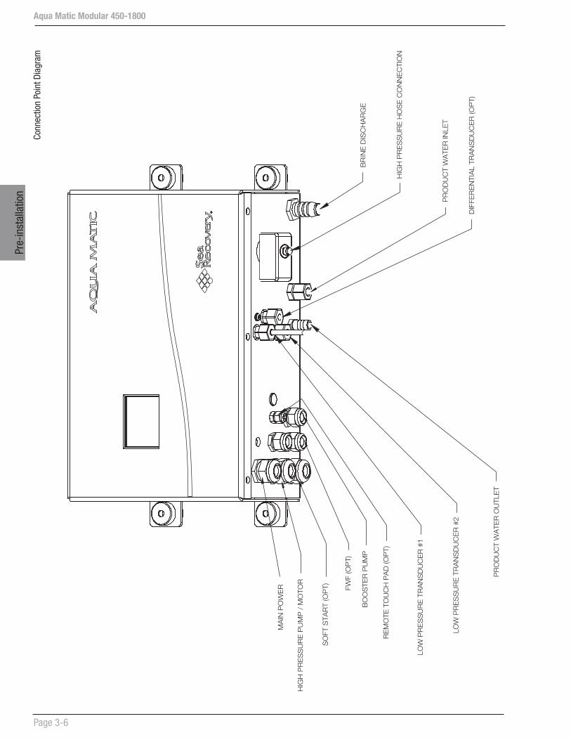
Conn
ectio
n Po
int D
iagr
am
MA
IN P
OW
ER FW
F (O
PT)
BO
OS
TER
PU
MP
SO
FT S
TAR
T (O
PT)
HIG
H P
RE
SS
UR
E P
UM
P /
MO
TOR
RE
MO
TE T
OU
CH
PA
D (O
PT
)
BR
INE
DIS
CH
AR
GE
HIG
H P
RE
SS
UR
E H
OS
E C
ON
NE
CTI
ON
DIF
FER
EN
TIA
L TR
AN
SD
UC
ER
(OP
T)
PR
OD
UC
T W
ATE
R O
UTL
ET
LOW
PR
ES
SU
RE
TR
AN
SD
UC
ER
#1
LOW
PR
ES
SU
RE
TR
AN
SD
UC
ER
#2
PR
OD
UC
T W
ATE
R IN
LET
Aqua Matic Modular 450-1800
Page 3-7
Pre-installation
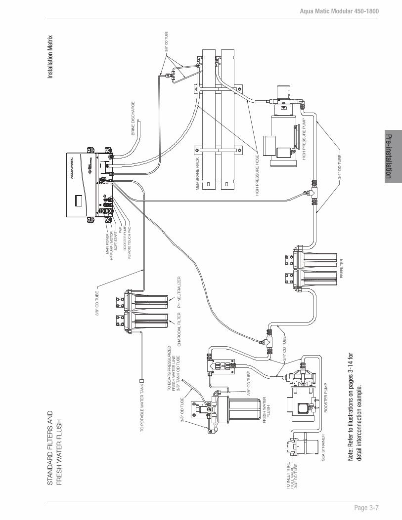
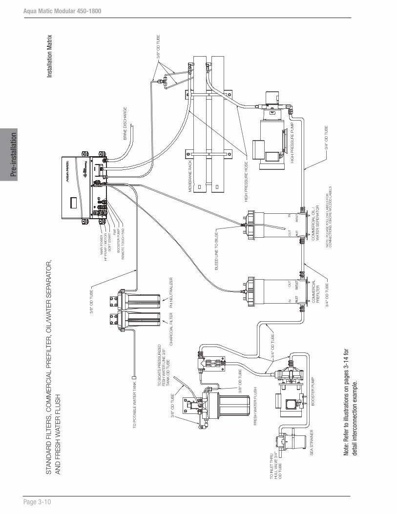
Note
: Ref
er to
illu
stra
tions
on
page
s 3-
14 fo
r de
tail
inte
rcon
nect
ion
exam
ple.
Inst
alla
tion
Mat
rixS
TAN
DA
RD
FIL
TER
S A
ND
FR
ES
H W
ATE
R F
LUS
H
TO B
OA
TS P
RE
SS
UR
IZE
D
FRE
SH
WA
TER
LIN
E
3/8"
TA
NK
OD
TU
BE
BO
OS
TER
PU
MP
S
EA
STR
AIN
ER
PR
EFI
LTE
R
FRE
SH
WA
TER
FLU
SH
CH
AR
CO
AL
FILT
ER
PH
NE
UTR
ALI
ZE
R
3/8"
OD
TU
BE
3/8"
OD
TU
BE
HIG
H P
RE
SS
UR
E H
OS
E
3/8"
OD
TU
BE
3/8"
OD
TU
BE
TO P
OTA
BLE
WA
TER
TA
NK
3/4"
OD
TU
BE
3/4"
OD
TU
BE
MA
IN P
OW
ER
FWF
BO
OS
TER
PU
MP
SO
FT S
TAR
TH
P P
UM
P /
MO
TOR
RE
MO
TE T
OU
CH
PA
DB
RIN
E D
ISC
HA
RG
E
HIG
H P
RE
SS
UR
E P
UM
P
ME
MB
RA
NE
RA
CK
TO IN
LET
THR
UH
ULL
VA
LVE
3/4"
OD
TU
BE
Aqua Matic Modular 450-1800
Page 3-8
Pre-
inst
alla
tion
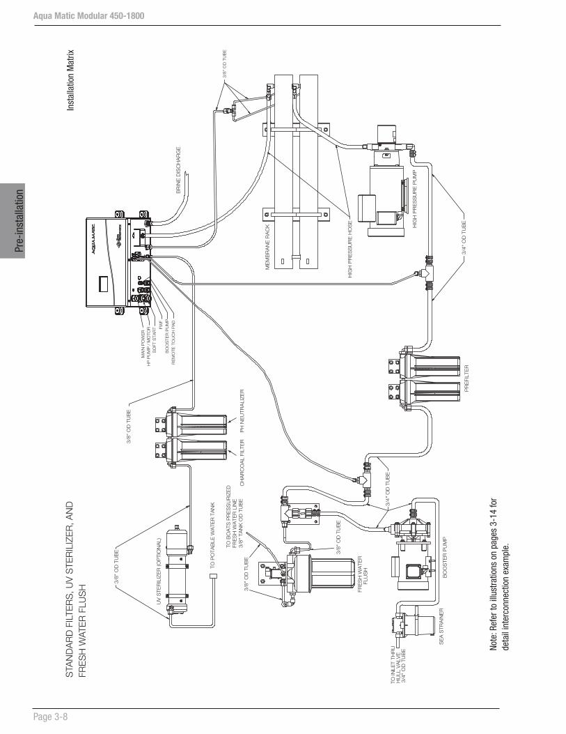
Note
: Ref
er to
illu
stra
tions
on
page
s 3-
14 fo
r de
tail
inte
rcon
nect
ion
exam
ple.
Inst
alla
tion
Mat
rixS
TAN
DA
RD
FIL
TER
S, U
V S
TER
ILIZ
ER
, AN
D
FRE
SH
WAT
ER
FLU
SH
TO B
OA
TS P
RE
SS
UR
IZE
D
FRE
SH
WA
TER
LIN
E
3/8"
TA
NK
OD
TU
BE
BO
OS
TER
PU
MP
SE
A S
TRA
INE
R
PR
EFI
LTE
R
FRE
SH
WA
TER
FLU
SH
CH
AR
CO
AL
FILT
ER
PH
NE
UTR
ALI
ZE
R
3/8"
OD
TU
BE
3/8"
OD
TU
BE
HIG
H P
RE
SS
UR
E H
OS
E
3/8"
OD
TU
BE
3/8"
OD
TU
BE
TO P
OTA
BLE
WA
TER
TA
NK
3/4"
OD
TU
BE
3/4"
OD
TU
BE
MA
IN P
OW
ER
FWF
BO
OS
TER
PU
MP
SO
FT S
TAR
TH
P P
UM
P /
MO
TOR
RE
MO
TE T
OU
CH
PA
DB
RIN
E D
ISC
HA
RG
E
HIG
H P
RE
SS
UR
E P
UM
P
ME
MB
RA
NE
RA
CK
TO IN
LET
THR
UH
ULL
VA
LVE
3/4"
OD
TU
BE
3/8"
OD
TU
BE
UV
STE
RIL
IZE
R (O
PTI
ON
AL)

Aqua Matic Modular 450-1800
Page 3-9
Pre-installation
Note
: Ref
er to
illu
stra
tions
on
page
s 3-
14 fo
r de
tail
inte
rcon
nect
ion
exam
ple.
Inst
alla
tion
Mat
rixS
TAN
DA
RD
FIL
TER
S, O
PTI
ON
AL
PLA
NK
TON
FIL
TER
, U
V S
TER
ILIZ
ER
, AN
D F
RE
SH
WAT
ER
FLU
SH
TO B
OA
TS P
RE
SS
UR
IZE
D
FRE
SH
WA
TER
LIN
E
3/8"
TA
NK
OD
TU
BE
BO
OS
TER
PU
MP
SE
A S
TRA
INE
R
PR
EFI
LTE
R
FRE
SH
WA
TER
FLU
SH
CH
AR
CO
AL
FILT
ER
PH
NE
UTR
ALI
ZE
R
3/8"
OD
TU
BE
3/8"
OD
TU
BE
HIG
H P
RE
SS
UR
E H
OS
E
3/8"
OD
TU
BE
3/8"
OD
TU
BE
TO P
OTA
BLE
WA
TER
TA
NK
3/4"
OD
TU
BE
3/4"
OD
TU
BE
MA
IN P
OW
ER
FWF
BO
OS
TER
PU
MP
SO
FT S
TAR
TH
P P
UM
P /
MO
TOR
RE
MO
TE T
OU
CH
PA
DB
RIN
E D
ISC
HA
RG
E
HIG
H P
RE
SS
UR
E P
UM
P
ME
MB
RA
NE
RA
CK
TO IN
LET
THR
UH
ULL
VA
LVE
3/4"
OD
TU
BE
3/8"
OD
TU
BE
UV
STE
RIL
IZE
R (O
PTI
ON
AL)
PLA
NK
TON
FI
LTE
R
(OP
TIO
NA
L)
Aqua Matic Modular 450-1800
Page 3-10
Pre-
inst
alla
tion
Note
: Ref
er to
illu
stra
tions
on
page
s 3-
14 fo
r de
tail
inte
rcon
nect
ion
exam
ple.
Inst
alla
tion
Mat
rixS
TAN
DA
RD
FIL
TER
S, C
OM
ME
RC
IAL
PR
EFI
LTE
R, O
IL/W
ATE
R S
EPA
RAT
OR
, A
ND
FR
ES
H W
ATE
R F
LUS
H
BO
OS
TER
PU
MP
S
EA
STR
AIN
ER
FRE
SH
WA
TER
FLU
SH
CO
MM
ER
CIA
L O
IL /
W
ATE
R S
EP
ER
ATO
R
NO
TE: P
LEA
SE
FO
LLO
W L
AB
ELS
FO
R
CO
NN
EC
TIO
NS
, IG
NO
RE
MO
LDE
D L
AB
ELS
INLE
TO
UTLE
TIN
LET
OUT
LET
BLE
ED
LIN
E T
O B
ILG
E
3/8"
OD
TU
BE
3/8"
OD
TU
BE
HIG
H P
RE
SS
UR
E H
OS
E
3/8"
OD
TU
BE
3/8"
OD
TU
BE
TO P
OTA
BLE
WA
TER
TA
NK
INO
UT
OU
TIN
3/4"
OD
TU
BE
3/4"
OD
TU
BE
3/4"
OD
TU
BE
MA
IN P
OW
ER
FWF
BO
OS
TER
PU
MP
SO
FT S
TAR
TH
P P
UM
P /
MO
TOR
RE
MO
TE T
OU
CH
PA
DB
RIN
E D
ISC
HA
RG
E
HIG
H P
RE
SS
UR
E P
UM
P
ME
MB
RA
NE
RA
CK
TO B
OAT
S P
RE
SS
UR
IZE
D
FE
SH
WAT
ER
LIN
E 3
/8"
TAN
K O
D T
UB
E
TO IN
LET
THR
U
HU
LL V
ALV
E 3
/4"
OD
TU
BE
CO
MM
ER
CIA
L
PR
EFI
LTE
R
CH
AR
CO
AL
FILT
ER
PH
NE
UTR
ALI
ZE
R

Aqua Matic Modular 450-1800
Page 3-11
Pre-installation
Note
: Ref
er to
illu
stra
tions
on
page
s 3-
14 fo
r de
tail
inte
rcon
nect
ion
exam
ple.
Inst
alla
tion
Mat
rix
BO
OS
TER
PU
MP
S
EA
STR
AIN
ER
FRE
SH
WA
TER
FLU
SH
CO
MM
ER
CIA
L O
IL /
W
ATE
R S
EP
ER
ATO
R
NO
TE: P
LEA
SE
FO
LLO
W L
AB
ELS
FO
R
CO
NN
EC
TIO
NS
, IG
NO
RE
MO
LDE
D L
AB
ELS
INLE
TO
UTLE
TIN
LET
OUT
LET
BLE
ED
LIN
E T
O B
ILG
E
3/8"
OD
TU
BE
3/8"
OD
TU
BE
HIG
H P
RE
SS
UR
E H
OS
E
3/8"
OD
TU
BE
3/8"
OD
TU
BE
INO
UT
OU
TIN
3/4"
OD
TU
BE
3/4"
OD
TU
BE
3/4"
OD
TU
BE
MA
IN P
OW
ER
FWF
BO
OS
TER
PU
MP
SO
FT S
TAR
TH
P P
UM
P /
MO
TOR
RE
MO
TE T
OU
CH
PA
DB
RIN
E D
ISC
HA
RG
E
HIG
H P
RE
SS
UR
E P
UM
P
ME
MB
RA
NE
RA
CK
TO B
OAT
S P
RE
SS
UR
IZE
D
FES
H W
ATE
R L
INE
3/8
" TA
NK
OD
TU
BE
TO IN
LET
THR
U
HU
LL V
ALV
E 3
/4"
OD
TU
BE
CO
MM
ER
CIA
L P
RE
FILT
ER
TO P
OTA
BLE
WA
TER
TA
NK
3/8"
OD
TU
BE
UV
STE
RIL
IZE
R (O
PTI
ON
AL)
CH
AR
CO
AL
FILT
ER
PH
NE
UTR
ALI
ZE
R
STA
ND
AR
D F
ILTE
RS
, CO
MM
ER
CIA
L P
RE
FILT
ER
, OIL
/WAT
ER
SE
PAR
ATO
R,
UV
STE
RIL
IZE
R, A
ND
FR
ES
H W
ATE
R F
LUS
H

Aqua Matic Modular 450-1800
Page 3-12
Pre-
inst
alla
tion
Note
: Ref
er to
illu
stra
tions
on
page
s 3-
14 fo
r de
tail
inte
rcon
nect
ion
exam
ple.
Inst
alla
tion
Mat
rixS
TAN
DA
RD
FIL
TER
S, C
OM
ME
RC
IAL
PR
EFI
LTE
R, O
IL/W
ATE
R S
EPA
RAT
OR
, U
V S
TER
ILIZ
ER
, OP
TIO
NA
L P
LAN
KTO
N F
ILTE
R A
ND
FR
ES
H W
ATE
R F
LUS
H
CO
NN
EC
TIO
NS
, IG
NO
RE
MO
LDE
D L
AB
ELS
HU
LL
INLE
TO
UTL
ETIN
LET
OU
TLET
INO
UT
OU
TIN
PLA
NK
TON
FILT
ER
(OP
T)
FRE
SH
WA
TER
FLU
SH
3/8"
OD
TU
BE
3/8"
OD
TU
BE
3/8"
OD
TU
BE
MA
IN P
OW
ER
FWF
BO
OS
TER
PU
MP
SO
FT S
TAR
TH
P P
UM
P /
MO
TOR
RE
MO
TE T
OU
CH
PA
D
BR
INE
DIS
CH
AR
GE
TO B
OAT
S P
RE
SS
UR
IZE
D
FES
H W
ATE
R L
INE
3/8
" TA
NK
OD
TU
BE
TO P
OTA
BLE
WA
TER
TA
NK
3/8"
OD
TU
BE
UV
STE
RIL
IZE
R (O
PTI
ON
AL)
CH
AR
CO
AL
FILT
ER
PH
NE
UTR
ALI
ZE
R
BO
OS
TER
PU
MP
S
EA
STR
AIN
ER
CO
MM
ER
CIA
L O
IL /
W
ATE
R S
EP
ER
ATO
R
NO
TE: P
LEA
SE
FO
LLO
W L
AB
ELS
FO
R
BLE
ED
LIN
E T
O B
ILG
E
3/8"
OD
TU
BE
HIG
H P
RE
SS
UR
E H
OS
E
3/4"
OD
TU
BE
3/4"
OD
TU
BE
3/4"
OD
TU
BE
HIG
H P
RE
SS
UR
E P
UM
P
ME
MB
RA
NE
RA
CK
TO IN
LET
THR
U
VALV
E 3
/4"
OD
TU
BE
CO
MM
ER
CIA
LP
RE
FILT
ER

Aqua Matic Modular 450-1800
Page 3-13
Pre-installation
Note
: Ref
er to
illu
stra
tions
on
page
s 3-
14 fo
r de
tail
inte
rcon
nect
ion
exam
ple.
Inst
alla
tion
Mat
rixS
TAN
DA
RD
FIL
TER
S, C
OM
ME
RC
IAL
PR
EFI
LTE
R A
ND
OIL
/WAT
ER
SE
PAR
ATO
R
WIT
H O
PTI
ON
AL
DIF
FER
EN
TIA
L, U
V S
TER
ILIZ
ER
, AN
D F
RE
SH
WAT
ER
FLU
SH
INLE
TO
UTL
ET
INLE
TO
UTL
ET
INO
UT
OU
TIN
FRE
SH
WA
TER
FLU
SH
3/8"
OD
TU
BE
3/8"
OD
TU
BE
3/8"
OD
TU
BE
MA
IN P
OW
ER
FWF
BO
OS
TER
PU
MP
SO
FT S
TAR
TH
P P
UM
P /
MO
TOR
RE
MO
TE T
OU
CH
PA
D
BR
INE
DIS
CH
AR
GE
TO B
OAT
S P
RE
SS
UR
IZE
D FE
SH
WAT
ER
LIN
E 3
/8"
TAN
K O
D T
UB
E
TO P
OTA
BLE
WA
TER
TA
NK
3/8"
OD
TU
BE
UV
STE
RIL
IZE
R (O
PTI
ON
AL)
CH
AR
CO
AL
FILT
ER
BO
OS
TER
PU
MP
S
EA
STR
AIN
ER
CO
MM
ER
CIA
L O
IL /
W
ATE
R S
EP
ER
ATO
R
NO
TE: P
LEA
SE
FO
LLO
W L
AB
ELS
FO
R
CO
NN
EC
TIO
NS
, IG
NO
RE
MO
LDE
D L
AB
ELS
BLE
ED
LIN
E T
O B
ILG
E
3/8"
OD
TU
BE
HIG
H P
RE
SS
UR
E H
OS
E
3/4"
OD
TU
BE
3/4"
OD
TU
BE
3/4"
OD
TU
BE
HIG
H P
RE
SS
UR
E P
UM
P
ME
MB
RA
NE
RA
CK
TO IN
LET
THR
U
HU
LL V
ALV
E 3
/4"
OD
TU
BE
CO
MM
ER
CIA
L
PR
EFI
LTE
R
OP
TIO
NA
L
DIF
FER
EN
TIA
L
PH
NE
UTR
ALI
ZE
R

Aqua Matic Modular 450-1800
Page 3-14
Pre-
inst
alla
tion
I H
HP
Pum
p
FM
34"
34
"
1 4"
38"
FM
SP
nlet
Thr
uul
l Fitt
ing
Sea
Coc
kVa
lve
Sea
Stra
iner
Cle
anin
gO
utle
t Val
ve
Boos
ter
Pum
p
FWF
Filt
er
FWF
Valv
e
Soft
Star
t
Elec
.
Cha
ssis
Touc
hSc
reen
Rem
ote
Pane
l
Buck
et
Ship
’sH
ull
Tank
Cle
anin
gIn
let V
alve
Cle
anin
gIn
let V
alve
UV
Ster
ilzer
PH Filt
erC
harc
oal
Filt
er
Div
ersi
onVa
lve
Flow
Met
er
Salin
ity
Prob
e
Back
Pre
ssur
eRe
gula
tor
Pres
sure
Vess
el
HP
Pum
p
LP Tran
s
LP Man
ifold
HP
Tran
s
HP
Mem
bra
neIn
let
LP Inle
t
Flow
Met
er
Pres
sure
Vess
el
HP
Man
ifold
(Sta
ndar
d)
Not
e 1:
The
HP
& D
iff. P
ress
ure
Tran
sduc
er c
onne
ctio
n d
epen
ds
on t
he H
P P
ump
use
d.
Not
e 2:
Thi
s ill
ustr
atio
n m
ay n
ot s
how
all
the
com
pon
ents
use
d o
n a
syst
em.
AQ
UA
SE
RIE
S
CO
MP
ON
EN
T IN
TER
CO
NN
EC
T E
XA
MP
LE

Aqua Matic Modular 450-1800
Page 3-15
Pre-installation
Not
e 1:
The
HP
& D
iff. P
ress
ure
Tran
sduc
er c
onne
ctio
n d
epen
ds
on t
he H
P P
ump
use
d.
Not
e 2:
Thi
s ill
ustr
atio
n m
ay n
ot s
how
all
the
com
pon
ents
use
d o
n a
syst
em.
AQ
UA
SE
RIE
S
CO
MP
ON
EN
T IN
TER
CO
NN
EC
T E
XA
MP
LE
HP
Pum
p
FM
34"
34
"
1 4"
38"
FM
SP
Inle
t Thr
uH
ull F
ittin
g
Sea
Coc
kVa
lve
Sea
Stra
iner
Cle
anin
gO
utle
t Val
ve
Boos
ter
Pum
p
FWF
Filt
er
FWF
Valv
e
Soft
Star
t
Elec
. C
hass
is
Touc
hSc
reen
Rem
ote
Pane
l
Buck
et
Ship
’sH
ull
Tank
Cle
anin
gIn
let V
alve
Brin
eD
isch
arge
UV
Ster
ilzer
PH Filt
erC
harc
oal
Filt
er
Div
ersi
onVa
lve
Flow
Met
er
Salin
ity
Prob
e
Back
Pre
ssur
eRe
gula
tor
Pres
sure
Vess
el
HP
Pum
pLP Tr
ans
LP Man
ifold
HP
Tran
s
HP
Mem
bra
neIn
let
LP Inle
t
Flow
Met
er
Pres
sure
Vess
el
Oil-
Wat
erSe
p
HP
Man
ifold
(Op
tiona
l)(O
ptio
nal)
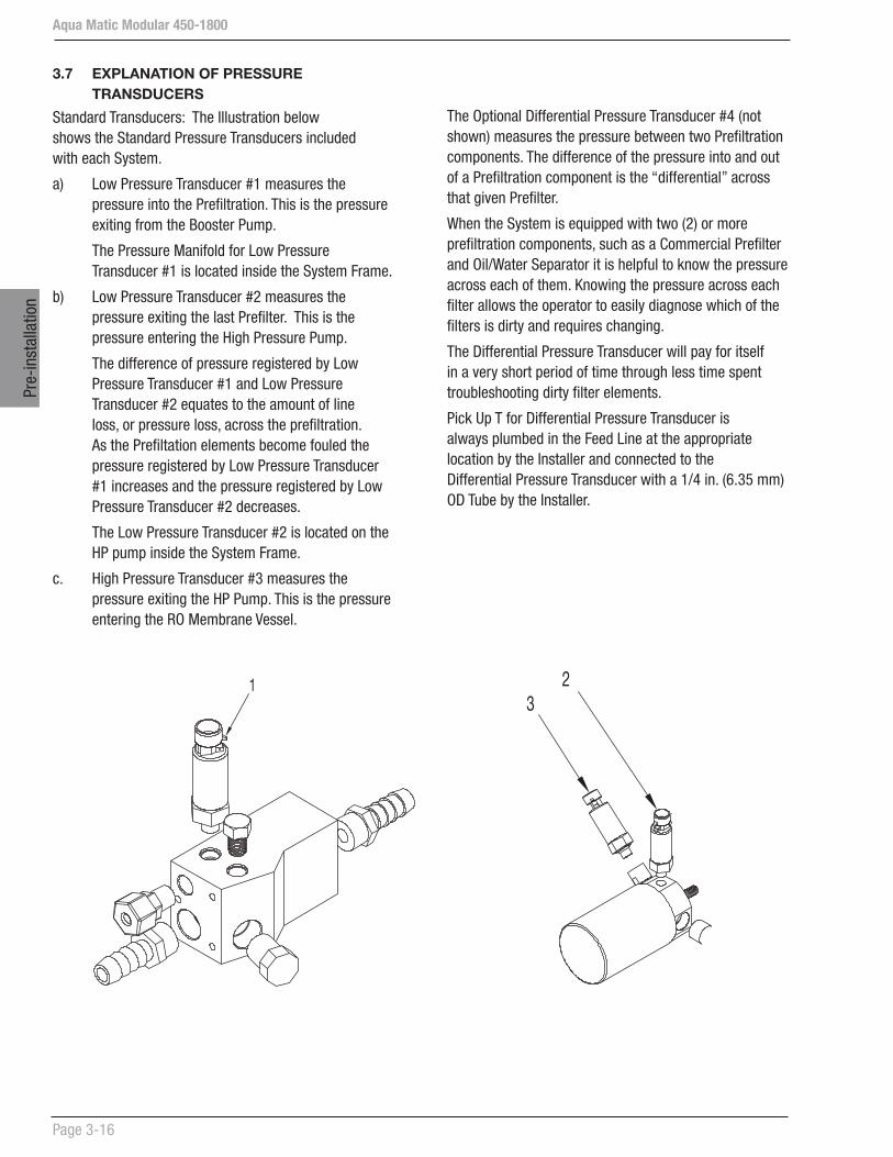
Aqua Matic Modular 450-1800
Page 3-16
Pre-
inst
alla
tion
The Optional Differential Pressure Transducer #4 (not shown) measures the pressure between two Prefiltration components. The difference of the pressure into and out of a Prefiltration component is the “differential” across that given Prefilter.
When the System is equipped with two (2) or more prefiltration components, such as a Commercial Prefilter and Oil/Water Separator it is helpful to know the pressure across each of them. Knowing the pressure across each filter allows the operator to easily diagnose which of the filters is dirty and requires changing.
The Differential Pressure Transducer will pay for itself in a very short period of time through less time spent troubleshooting dirty filter elements.
Pick Up T for Differential Pressure Transducer is always plumbed in the Feed Line at the appropriate location by the Installer and connected to the Differential Pressure Transducer with a 1/4 in. (6.35 mm) OD Tube by the Installer.
3.7 EXPLANATION OF PRESSURE TRANSDUCERS
Standard Transducers: The Illustration below shows the Standard Pressure Transducers included with each System.
a) Low Pressure Transducer #1 measures the pressure into the Prefiltration. This is the pressure exiting from the Booster Pump.
The Pressure Manifold for Low Pressure Transducer #1 is located inside the System Frame.
b) Low Pressure Transducer #2 measures the pressure exiting the last Prefilter. This is the pressure entering the High Pressure Pump.
The difference of pressure registered by Low Pressure Transducer #1 and Low Pressure Transducer #2 equates to the amount of line loss, or pressure loss, across the prefiltration. As the Prefiltation elements become fouled the pressure registered by Low Pressure Transducer #1 increases and the pressure registered by Low Pressure Transducer #2 decreases.
The Low Pressure Transducer #2 is located on the HP pump inside the System Frame.
c. High Pressure Transducer #3 measures the pressure exiting the HP Pump. This is the pressure entering the RO Membrane Vessel.
23
1

Aqua Matic Modular 450-1800
Page 3-17
Pre-installation
Damage to the system caused by the operation of the system without R.O. Membrane Elements installed:
• Is NOT covered by the Sea Recovery warranty
• Is the liability of the installer if the installer did not notify the end user.
• Is the liability of the end user if the installer notified the end user that the R.O. Membranes were not installed and to not operate the system without the R.O. Membrane elements installed.
3.8 RO MEMBRANE ELEMENT NOTES
CAUTION: Some systems are shipped WITHOUT the Reverse Osmosis Membrane Element. This is to accommodate Boat Builders that will install the System well in advance of commissioning the boat and the System.
DOES THIS SYSTEM HAVE R.O. MEMBRANE(S) INSTALLED OR NOT?
If not, is it your intention to install the R.O. membrane(s) at this time, or do you wish to install them at a later date when the boat is commissioned?
If the R.O. membrane element has been installed, there will be a R.O. Membrane Element Serial Number tag, illustrated below, attached to the High Pressure Vessel(s). Find this Serial Number tag to ensure that the R.O. membrane element(s) has been installed.
If the R.O. membrane element Serial Number tag is missing or does not contain a serial number and date then the R.O. membranes are not installed. If the R.O. membrane elements are not installed and you wish to install them at this time contact Sea Recovery and supply us with your original Purchase Order Number, Sea Recovery’s Invoice Number, and this System’s Serial Number.
WARNING: If the reverse osmosis membrane element is not to be installed at this time, ensure that you leave a visible note at the system controller and at the front of the control panel informing the end user that:The Reverse Osmosis Membrane Elements are not installed; to contact the factory for the R.O. Membrane Elements; and DO NOT operate the system without the R.O. Membrane Elements installed.
** Extensive damage will occur if the system is operated without the R.O. Membrane Elements installed. **
3.9 COMPONENT DESCRIPTIONS
All components supplied by Sea Recovery, both standard and optional, are described in this section along with items required or desired by the installer. The location, operation, and purpose of each major component are briefly explained in this section.
Use of third party, Non Sea Recovery, components will lead to premature failure, added operating and maintenance costs, and increased labor. Using 3rd party, Non Sea Recovery, components will void any and all Sea Recovery Warranty. We only wish to help you enjoy the luxury of owning a Sea Recovery R.O. System. Treat it properly by using only Sea Recovery supplied parts, consumable, and accessories.
PREFILTRATION SECTION:
The Prefiltration Section filters and delivers the feed water into the system. The raw feed water is filtered to remove suspended solids larger than 5 Micron size (5/1,000,000 of a meter). The prefiltration protects the High Pressure Pump from premature wear and the Reverse Osmosis Membrane Element from premature fouling.
1. Inlet Thru Hull Fitting with Forward Facing Scoop ** is the point at which the feed water enters the system. It is important that the installer utilizes a forward facing scoop so that the system receives a positive flow of water as the boat is under way.
Note: Symbol Used in this Section.
** Indicates items supplied by owner/installer
*** Indicates optional equipment.
Sea Recovery
SERIAL NO:FLOW:DATE:
Rancho Dominguez, California 90220 U.S.A.Tel: 1-310-637-3400 | Fax: 1-310-637-3430 Email: [email protected]
087945021505BRINE INLET ENDOctober 15, 2005

Aqua Matic Modular 450-1800
Page 3-18
Pre-
inst
alla
tion
CAUTION: A flush inlet thru-hull fitting will cause a vacuum as the boat is under way, and will cause loss of feed water flow, cavitation of the feed pump and high pressure pump resulting in continual system shut down.
CAUTION: If the thru-hull fitting is placed in a position on the underside of the hull that allows air to continually enter the thru-hull fitting, it will cause the system to continually shut down due to loss of feed water.
NOTE: The resulting failure of the system to remain in operation is attributed to improper installation, is the liability of the installer, and is not covered by the Sea Recovery warranty.
2. Sea Cock Valve ** is used in a ship installation for safety reasons to close the feed water line during repair, maintenance, and disuse of the system.
3. Sea Strainer has a clear bowl with bronze body filter housing containing a cleanable monel filter screen. The Sea Strainer filters out large particulate matter and suspended particles that would otherwise damage the Booster Pump and prematurely foul the cartridge Prefilter Element.
4. Booster Pump supplies a positive pressure to the Pre-filters and onward to the High Pressure Pump. The Booster Pump has a performance curve of 85 Ft Head 35 PSI (2.41 BAR) @ 60 Hz with a feed water flow of 4.5 GPM (17 LPM).
The resulting pressure at the High Pressure Pump depends on the final installation configuration and condition of Prefiltration elements.
5. Low Pressure Transducer #1 Booster Pump Outlet/ 1st Prefilter Inlet for line pressure pick up from the outlet of the Booster Pump to the 1st Prefiltration component.
6. Plankton Filter *** This optional filter assembly contains a cleanable ultra fine monel mesh screen. The mesh screen removes suspended solids or biological growth such as plankton. It also provides longer life to the Pre-filter Elements and in turn provides lower system maintenance costs. The Plankton Filter is available as a single housing or dual housing.
7. Multi Media Filter *** This optional filter assembly contains a back-washable bed of sand and gravel. The sand traps suspended solids larger than 30 micron which provides longer life to the pleated cartridge prefilter elements minimizing maintenance intervals, maintenance labor, and filter element cost.
WARNING: PREFILTER ELEMENT Do not use third party prefilter elements, use only Sea Recovery prefilter elements. Third party prefilter elements do not properly fit and the seams fall apart. They also allow by-pass resulting in extensive and very costly damage to the High Pressure Pump as well as premature fouling of the R.O. Membrane Element(s).
8. Commercial Prefilter takes the place of the Dual Prefilter. The 5 micron Commercial Prefilter cartridge element contains 37.5 sq. ft. (3.5 square meters) of filtering surface area. This oversize cartridge gives much longer filter element life greatly extending the time interval between required maintenance and reduces maintenance labor and prefilter element replacement cost.
CAUTION: PREFILTER ELEMENT Do not use “string wound” or “fiber” prefilter elements. String wound and fiber filter elements are designed for the Photographic Film Developing Industry. When used in sea water, they will plug up rapidly in 1/10th or less the time of a Sea Recovery supplied prefilter cartridge element. This will cause frequent shut downs of the system and very frequent changing which will result in very high cost of maintenance, and user frustration.
9. Dual Pre-Filter removes suspended solids in two stages. The feed water passes first through a 20 micron cartridge then a 5 micron cartridge. By stepping the filtration, both prefilter elements gain longer life and require less maintenance labor and prefilter element replacement cost.
10. T-Connector Pressure Differential Pick-up *** is included with Pressure Differential Transducer #4 for line differential pressure pick up between optional prefiltration components to the Low

Aqua Matic Modular 450-1800
Page 3-19
Pre-installation
Differential Pressure Transducer. Depending on Prefiltration configuration this T-Connector may not be necessary as illustrated on Page 3-7 and 3-8. Depending on the System style and perfiltration configuration, one of the two Pressure Pick-Up Tee styles may be used.
11. Pressure Differential Transducer #4 *** (optional) for line differential pressure across prefiltration components. Allows the operator to determine which prefiltration component requires servicing.
WARNING: OIL WATER SEPARATOR ELEMENT Use only Sea Recovery supplied filter elements. Third party oil water separator elements do not properly fit and the seams fall apart. They also allow by-pass resulting in extensive and very costly damage to the High Pressure Pump as well as premature fouling of the R.O. Membrane Element(s).
12. Oil/Water Separator Filter removes oil present in the feed water.
CAUTION: Oil permanently destroys the R.O. Membrane element. It is recommended that the user avoid operating the Sea Recovery R.O. System in oil polluted waters if the Oil/Water Separator Filter is not installed.
13. Low Pressure Transducer #2 measures line pressure after all prefiltration and prior to the inlet of the High Pressure Pump.
14. Low Pressure Transducer Manifold supports the Low Pressure and Differential Pressure Transducers.
PRESSURIZATION SECTION:
The Pressurization Section provides the necessary pressure to force the product water through the R.O. membrane element.
1. High Pressure Pump and Motor Assembly is a Radial Axial Positive Displacement Plunger Pump made of high grade Duplex material specifically designed for sea water Reverse Osmosis applications. The Pump is self lubricated and does not require oil. The Pump is connected to the attached electric motor with a flex coupler and safety bell housing.
2. High Pressure Hose, HP Pump Outlet to R.O. Membrane and Vessel Assembly Inlet, transfers pressurized sea water from the High Pressure Pump to the inlet of the R.O. Membrane Element.
3. R.O. Membrane Element and Vessel #1 The Membrane Element allows potable water molecules to pass through while rejecting the salt ions. Only 7% to 28%, depending on specific model, of the Seawater Feed becomes fresh Product Water. The remainder carries the rejected salt ions out of the R.O. Membrane Element in a concentrated brine stream. The R.O. System may have one or two R.O. Membrane Element & Vessel in series depending on the specific model and system capacity.
4. R.O. Membrane Element and Vessel #2 is connected in series with the first R.O. Membrane Element and Vessel. The Sea Recovery R.O. System will have either one or two R.O. Membrane Element & Vessel depending on the model. The 2nd R.O. Membrane Element and Vessel may be added at any time to a system with only one. Adding the 2nd R.O. Membrane Element and Vessel will double the System’s production.
5. High Pressure Hose R.O. Membrane Vessel Assembly Outlet to High Pressure Manifold Inlet.
6. High Pressure Transducer measures the System Operating Pressure from the Outlet of the High Pressure Pump through the R.O. Membrane and Vessels.
7. Automatic Motor Actuated Back Pressure Regulator is a U.S. Patent Pending device that automatically adjusts the system operating pressure to varying feed water temperatures and salinities making the System a truly self functioning and fully automatic watermaker.
BRINE DISCHARGE SECTION:
The Brine Discharge Section carries the Brine Discharge water, exiting from the R.O. Membrane Element, back to the feed source.
1. Brine Discharge Flow Meter measures the brine water rate of flow from the R.O. Membrane Element in gallons or liters per hour. By adding the amount of Product Water flow to the Brine Discharge Flow the operator is able to determine the total Feed Water Flow.

Aqua Matic Modular 450-1800
Page 3-20
Pre-
inst
alla
tion
2. Brine Discharge T-Connector collects the brine discharge water and unpotable product water.
3. Brine Discharge Connector attaches to the over board thru-hull fitting for connecting the brine discharge hose.
4. Multi Media Filter Waste “T” *** is included with the Multi Media Filter. This waste T is installed in line at the Brine Discharge fitting to allow discharge of the waste from the Multi Media Filter during the back wash and rinse operations, and the brine discharge water from the system.
5. Thru Hull Brine Discharge Fitting ** should be installed above water level for discharge of the Brine Discharge Water from the system.
PRODUCT WATER SECTION:
The Product Water Section gives a visual indication of the clarity, quantity, and quality of the product water. Post Filtration is the final step in Product Water quality control. The Post Filtration Subsystem is designed to limit unpleasant odor and taste, adjust the pH to neutral, and sterilize biological matter which may have passed through the R.O. Membrane Element.
1. Product Water T-Connector combines the product water from the two individual R.O. Membrane Elements.
2. Temperature Compensated Salinity Probe electronically determines whether the salinity content of the Product Water is acceptable. This Salinity Probe is temperature compensated and provides an accurate measurement of Product Water quality.
3. Flow Meter, Product Water electronically measures the rate of Product Water flow, in gallons or liters per hour.
4. 3-Way Product Water Diversion Valve, Electric Solenoid Actuated. The Controller energizes this valve to the “Potable” position when the system produces water which meets the low salinity requirement. If the Product Water being produced is “Unpotable”, or high in salinity, then no signal is sent to the valve, and it thus remains in the normal open position. The “fail safe” normal open position diverts the unpotable Product Water to discharge.
5. Charcoal Filter removes foul odors from the Product Water. Sulfurous odor (rotten egg smell) is caused when biological matter dies and decays in
the feed water section. Fresh water flushing of the system helps to minimize this odor.
6. pH Neutralizer Filter The pH value of pure water is pH7 which is regarded as neutral. pH values from 0-7 indicate acidity and pH values from 7-14 indicate alkalinity. The product water from an R.O. System will be slightly acidic because most of the naturally occurring high pH calcium carbonate has been removed. The product water from an R.O. System will also be very soft for the same reason. The product water pH will be approximately 6.5 pH. The pH Neutralizer Filter dissolves calcium carbonate back into the product water bringing the pH level to neutral at approximately pH 7.
7. Ultra Violet Sterilizer *** sterilizes at least 99.9% of any virus, bacteria, and other micro-organisms which may pass through the R.O. membrane element. The UV sterilizer is recommended if the Product Water Storage Tank is not otherwise treated by means such as chlorination.
8. Product Water Connector attaches to the Potable Water unpressurized tank for connection of the Product Water hose.
FRESH WATER SYSTEM
The Fresh Water System represents the boat or home’s fresh water pressurized system. Pressurized fresh water is required to supply the System Fresh Water Flush.
1. Potable Water Storage Tank** may be any container suitable for storing Potable Water, i.e. existing water storage tank on a boat or cistern for a home.
2. Fresh Water Pressure Pump** delivers fresh water throughout the boat, or home. In order to provide the required flow of water to the System during the Fresh Water Flush cycle, this pump must deliver up to 1 U.S. Gallons (3.8 Liters) Per Minute at 25 to 60 PSI (172 to 414 kPa).
3. Air Entrainment Tank** (accumulator) is sometimes installed into the boat or home’s fresh water line to eliminate pulsations from and reduce demand on the Fresh Water Pressure Pump. This tank stores pressurized fresh water for delivery to the boat or home’s fresh water piping.

Aqua Matic Modular 450-1800
Page 3-21
Pre-installation
FRESH WATER FLUSH SECTION
The Fresh Water Flush Section includes a Carbon Filter and an Automatic Motor Actuated Ball Valve that automatically flushes the system with fresh water. This process is automatic at each shut down of the system and repeats automatically every preset number of days. Fresh Water Flushing replaces the seawater in the system with less corrosive fresh water, and this also reduces the biological growth and subsequent decay that naturally occur if the sea water is not flushed from the system with fresh water.
1. Fresh Water Flush 2-way solenoid valve ***automatically actuates at system shut down and every preset number of days there after to flush the system with fresh water.
2. Fresh Water Flush Check Valve *** prevents feed water from entering the fresh water line.
3. Fresh Water Flush Charcoal Filter *** removes chlorine, if present, in the fresh water prior to flowing through the R.O. Membrane Element.
4. Fresh Water Flush Check Valve *** routs the fresh water through the system.
5. Cleaning Bucket ** can be any non ferrous container capable of holding at least 10 U.S. Gallons (37.8 Liters) of water. This container is used during the R.O. Membrane Element cleaning, storing, or winterizing process.
6. Rinse Clean Inlet Valve *** These Optional Valves are mounted separately on singular individual plates or together on a double plate.
The Rinse Clean Inlet Valve is used in conjunction with the Rinse Clean Outlet Valve simplifies the storage and cleaning procedures by allowing the operator to turn a valve rather than disconnect a hose. Also used for a manual fresh water flush if the Automatic Fresh Water Flush System is not installed. The Rinse Clean Valves are available on single valve mounting plates or on double valve mounting plate.
7. Rinse Clean Outlet Valve *** used in conjunction with and identical to the Rinse Clean Inlet Valve simplifies the storage and cleaning procedures by allowing the operator to turn a valve rather than disconnect a hose.
ELECTRONIC SECTION
The Electronic Section measures water quality, controls the direction of Product Water flow, Starts and Stops the pumps, and contains the central electrical connection point of the system. It also ensures only potable Product Water passes into the Product Water Storage Tank.
1. System Touch Panel is where all system functions are accessed by touching the intuitive screen and where all operating conditions are monitored.
2. Electrical Control Box contains all electrical and electronic components that control the system.
3. Remote Control Touch Panel *** allows for remote control, operation, and monitoring of the system.
4. Soft Start *** The soft start, used only in AC Single Phase systems, reduces the initial startup amperes required to start the High Pressure Pump Motor and in turn allows a smaller sized KW generator to start the system. Starting amperage is reduced by 40% with the Soft Start installed.
Not Numbered:
Fresh Water Tank Low Level Switch ** owner/• installer supplied provides an optional feature to the System Control Logic that works in conjunction with the Automatic Fresh Water Flush option.
When installed and connected to the Main Printed Circuit Board, the Fresh Water Tank Low Level Switch must be connected as a N.O. (Normally Open) 1PST (One Pole Single Throw) switch.
When the Fresh Water Tank is empty the switch is Open. As water rises a few inches in the tank the switch Closes. This informs the System Control Logic that there is sufficient Fresh Water to perform the Automatic Fresh Water Flush Cycle.
Fresh Water Tank High Level Switch ** owner/• installer supplied provides an optional feature to the System Control Logic that allows the System to shut off automatically when the Fresh Water Tank is full, when the System is operated in the Automatic mode. Additionally, the System will not start in the Automatic mode when the Fresh Water Tank High Level Switch signals the System Control Logic that the Fresh Water Tank is full.
When installed and connected to the Main Printed Circuit Board, the Fresh Water Tank High Level Switch must be connected as a N.C. (Normally Closed) 1PST (One Pole Single Throw) switch.

Aqua Matic Modular 450-1800
Page 3-22
Pre-
inst
alla
tion
When the Fresh Water Tank is several inches below the full mark the switch is Closed. As water rises and reaches the top of the full mark the switch Opens. This informs the System Control Logic that the Fresh Water Tank is full.
If operation of the System is desired when the Fresh Water Tank Switch signals the System Control Logic that the Fresh Water Tank is full then the System may be operated in the Manual mode.

Electrical
Aqua Matic Modular 450-1800
Section 4 - ELECTRICAL INFORMATION

Elec
trica
l

Aqua Matic Modular 450-1800
Page 4-1
Electrical
4 ELECTRICAL INFORMATION
4.1 ELECTRICAL REQUIREMENTS AND INFORMATION
Following are general electrical requirements and information for Aqua Matic Modular models.
CAUTION: DO NOT PERFORM INSTALLATION UNLESS:
1. The System Feed Water Sea Cock Valve is closed.
2. The system main electrical disconnect switch is switched “OFF”, LOCKED, and TAGGED.
WARNING: ELECTRICAL SHOCK HAZARD. A Volt / Ohm Meter will be necessary. The following installation procedures expose the installer to High Voltage and electrical shock hazard. Only attempt this if you are a qualified electrician and only if surrounding conditions are safe.
CAUTION: Always allow slack in electrical cables. Allow the cable to enter or leave from the strain relief in a straight manner for several inches to ensure proper connection, to relieve stress to the cable and fitting, and to allow ease of detachment and reattachment for maintenance or replacement. If electrical cables are pulled tight causing them to bend at the strain relief, they will pull out of the strain relief causing a dangerous electrical shock condition, the wire may break, and the strain relief will lose its water-tight integrity.
A. AMPERAGE NOTES
The Electric Motors within the Aqua Matic systems start in series with time delay between each motor starting after the Touch Screen “Start” Switch is pressed. First, the Booster Pump starts, then the main High Pressure Pump Electric Motor starts. Alternatively, the Booster Pump and High Pressure Pump may be started manually by accessing the manual operation mode from the Touch Screen.
During start up, the current of the Booster Pump Electric Motor surges to “Locked Rotor” amperage for a fraction
of a second after which the current drops to normal running load. Then the High Pressure Pump Electric Motor starts and surges to “locked Rotor” amperage for a fraction of a second after which the current drops to normal running load.
Therefore, the maximum surge current equals the Booster Pump Electric Motor normal running amperage plus the High Pressure Pump Electric Motor starting amperage. Normal operational amperage equals the normal operating amperage of the Booster Pump Electric Motor plus the normal operating amperage of the High Pressure Pump Electric Motor.
B. POWER SOURCE REQUIREMENTS
Check line voltage and frequency to ensure that it agrees with system nameplate. Grounding and circuit protection should be done in accordance with National Electrical Code. See connection diagram on nameplate of motor or refer to the diagrams within this manual.
C. MOTOR ROTATION
Refer to Booster Pump and High Pressure Pump markings to determine proper rotation.
Three Phase Systems: Ensure proper rotation by jogging each motor from the manual operation mode.
Voltage AC Systems
HZ (AC)
Min. HZ
Max. HZ
Min. Voltage
Max. Voltage
120 VAC 60 HZ 58 Hz 62 Hz 108 VAC
132 VAC
230 VAC 60 HZ 58 Hz 62 Hz 207 VAC
253 VAC
100 VAC 50 HZ 48 Hz 52 Hz 90 VAC 110 VAC
220 VAC 50 HZ 48 Hz 52 Hz 198 VAC
242 VAC

Aqua Matic Modular 450-1800
Page 4-2
Elec
trica
l
4.2. ELECTRICAL MOTOR SPECIFICATIONS
(H.P. = Horse Power; RPM = Revolutions Per Minute; FLA = Full Load Amperes; LRA = Locked Rotor Amperes @ Start Up)
ALTERNATING CURRENT SYSTEMS:
Single Phase Alternating Current:
High Pressure Pump Motor Booster Pump Motor
VAC Hz H.P RPM FLA LRA H.P RPM FLA LRA
110 50 3 2850 23 89 0.5 2850 7.4 20
220 50 3 2850 11.5 44 0.5 2850 3.7 10
115 60 3 3450 25.4 86 0.5 3450 9.4 20
230 60 3 3450 12.7 43 0.5 3450 4.7 10
Three Phase Alternating Current:
High Pressure Pump Motor Booster Pump Motor
VAC Hz H.P RPM FLA LRA H.P RPM FLA LRA
220 50 2.5 2850 7.9 24.9 0.5 2850 2.5 8.2
380 50 2.5 2850 4.6 14.4 0.5 2850 1.5 4.7
230 60 3 3450 7.6 23.8 0.5 3450 2.4 7.9
460 60 3 3450 3.8 11.9 0.5 3450 1.2 3.9
4.3. RECOMMENDED CIRCUIT BREAKER
Recommended circuit breaker supplying power to system amperage rating:
Operating Recommended
AC Voltage Phase Circuit Breaker
110 - 115 VAC Single 50 Ampere
220 - 230 VAC Single 25 Ampere
220 VAC Three 15 Ampere
380 VAC Three 10 Ampere
460 VAC Three 10 Ampere

Aqua Matic Modular 450-1800
Page 4-3
Electrical
4.4. RECOMMENDED POWER WIRE SIZE
Recommended power wire size to Aqua Matic system and pump motors:
RECOMMENDED POWER WIRE SIZE TO AQUA MATIC SYSTEM:
Operating Maximum Recommended Minimum Wire Size for Length of run
Voltage Phase Load 10 Ft / 3 meter 25 Ft / 8 meter 50 Ft / 15 meter
110-115 VAC Single 34.8 Ampere 10 AWG / 6 mm2 8 AWG / 10 mm2 8 AWG / 10 mm2
220-230 VAC Single 17.4 Ampere 12 AWG / 4 mm2 12 AWG / 4 mm2 12 AWG / 4 mm2
220-230 VAC Three 10.4 Ampere 14 AWG / 2.5 mm2 14 AWG / 2.5 mm2 14 AWG / 2.5 mm2
380 VAC Three 6.1 Ampere 14 AWG / 2.5 mm2 14 AWG / 2.5 mm2 14 AWG / 2.5 mm2
460 VAC Three 5 Ampere 14 AWG / 2.5 mm2 14 AWG / 2.5 mm2 14 AWG / 2.5 mm2
RECOMMENDED POWER WIRE SIZE TO AQUA MATIC BOOSTER PUMP:
Operating Maximum Recommended Minimum Wire Size for Length of run
Voltage Phase Load 10 Ft / 3 meter 25 Ft / 8 meter 50 Ft / 15 meter
110-115 VAC Single 9.4 Ampere 14 AWG / 2.5 mm2 14 AWG / 2.5 mm2 14 AWG / 2.5 mm2
220-230 VAC Single 4.7 Ampere 14 AWG / 2.5 mm2 14 AWG / 2.5 mm2 14 AWG / 2.5 mm2
220-230 VAC Three 2.5 Ampere 16 AWG / 1.5 mm2 16 AWG / 1.5 mm2 16 AWG / 1.5 mm2
380 VAC Three 1.5 Ampere 16 AWG / 1.5 mm2 16 AWG / 1.5 mm2 16 AWG / 1.5 mm2
460 VAC Three 1.2 Ampere 16 AWG / 1.5 mm2 16 AWG / 1.5 mm2 16 AWG / 1.5 mm2
RECOMMENDED POWER WIRE SIZE TO AQUA MATIC HIGH PRESSURE PUMP:
Operating Maximum Recommended Minimum Wire Size for Length of run
Voltage Phase Load 10 Ft / 3 meter 25 Ft / 8 meter 50 Ft / 15 meter
110-115 VAC Single 25.5 Ampere 12 AWG / 4 mm2 10 AWG / 6 mm2 10 AWG / 6 mm2
220-230 VAC Single 12.7 Ampere 14 AWG / 2.5 mm2 12 AWG / 4 mm2 12 AWG / 4 mm2
220-230 VAC Three 7.9 Ampere 14 AWG / 2.5 mm2 14 AWG / 2.5 mm2 14 AWG / 2.5 mm2
380 VAC Three 4.6 Ampere 14 AWG / 2.5 mm2 14 AWG / 2.5 mm2 14 AWG / 2.5 mm2
460 VAC Three 3.8 Ampere 14 AWG / 2.5 mm2 14 AWG / 2.5 mm2 14 AWG / 2.5 mm2

Aqua Matic Modular 450-1800
Page 4-4
Elec
trica
l
4.6. WIRE SIZE REFERENCES
Wire Size Cross Reference American Wire Gauge (AWG) vs. Metric Wire Sizes
4.5. WIRE INSERTION TO TERMINAL STRIPS
AWG Diameter Square Diameter Square
Inch Inch (In2) Millimeters Millimeters (mm2)
0 0.46 0.1661 11.684 107.1649
0 0.4096 0.1317 10.4038 84.9683
0 0.3648 0.1045 9.2659 67.398
0 0.3249 0.0829 8.2525 53.4609
1 0.2893 0.0657 7.3482 42.3871
2 0.2576 0.0521 6.543 33.6069
3 0.2294 0.0413 5.8268 26.6516
4 0.2043 0.0328 5.1892 21.1385
6 0.162 0.0206 4.1148 13.2913
8 0.1285 0.013 3.2639 8.3626
10 0.1019 0.0082 2.5883 5.2588
12 0.0808 0.0051 2.0523 3.3064
14 0.0641 0.0032 1.6281 2.0809
16 0.0508 0.002 1.2903 1.307
18 0.0403 0.0013 1.0236 0.8225
20 0.032 0.0008 0.8128 0.5186
22 0.0254 0.0005 0.6452 0.3267

Aqua Matic Modular 450-1800
Page 4-5
Electrical
American Wire Gauge Metric Wire Gauge Metric Wire
AWG dia inch sq. inch dia mm sq mm Size mm2
0 0.46 0.1661 11.684 107.1649 100
0 0.4096 0.1317 10.4038 84.9683 85
0 0.3648 0.1045 9.2659 67.398 65
0 0.3249 0.0829 8.2525 53.4609 50
1 0.2893 0.0657 7.3482 42.3871 40
2 0.2576 0.0521 6.543 33.6069 32
3 0.2294 0.0413 5.8268 26.6516 32
4 0.2043 0.0328 5.1892 21.1385 19
6 0.162 0.0206 4.1148 13.2913 13
8 0.1285 0.013 3.2639 8.3626 8
10 0.1019 0.0082 2.5883 5.2588 5
12 0.0808 0.0051 2.0523 3.3064 3
14 0.0641 0.0032 1.6281 2.0809 2
16 0.0508 0.002 1.2903 1.307 1
18 0.0403 0.0013 1.0236 0.8225 0.8
20 0.032 0.0008 0.8128 0.5186 0.5
22 0.0254 0.0005 0.6452 0.3267 0.35
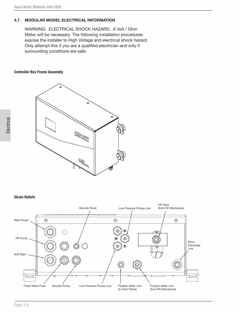
Aqua Matic Modular 450-1800
Page 4-6
Elec
trica
l
4.7. MODULAR MODEL ELECTRICAL INFORMATION
WARNING: ELECTRICAL SHOCK HAZARD. A Volt / Ohm Meter will be necessary. The following installation procedures expose the installer to High Voltage and electrical shock hazard. Only attempt this if you are a qualified electrician and only if surrounding conditions are safe.
Controller Box Frame Assembly
Strain Reliefs
Main Power
Fresh Water Flush Booster Pump Low Pressure Pickup Line
HP Pump
Soft Start
Potable Water Line(to Post Filters)
Product Water Line(from RO Membrane)
Remote Panel Low Pressure Pickup LineHP Hose (from RO Membrane)
Brine Discharge Line

Aqua Matic Modular 450-1800
Page 4-7
Electrical
Electrical Motor Wiring-Single Phase
NOTES
1. CONNECTIONS ARE SHOWN FOR CCW ROTATION FACING
END OPPOSITE SHAFT EXTENSION (STD). FOR CW
ROTATION, INTERCHANGE 5 AND 8 INTERNALLY.
2. OPTIONAL THERMOSTAT IS PROVIDED WHEN SPECIFIED.
3. MULTIPLE CAPACITORS ARE CONNECTED IN PARALLEL
UNLESS OTHERWISE SPECIFIED.
4. LEAD COLORS ARE OPTIONAL. LEADS MUST ALWAYS BE
NUMBERED AS SHOWN.
Sea Recovery BOOSTER PUMP ELECTRIC MOTORWINDINGS DIAGRAM CD0093SINGLE PHASE 50/60 Hz110-115 VAC // 220 - 230 VACRPM @ 50 Hz 2850 - @ 60 Hz 3450
VOLTAGE LINE A LINE B JOIN
220 - 230 VAC 1 4 2, 3
110 - 115 VAC 1, 3 2, 4 --
NOTES
1. CONNECTIONS ARE SHOWN FOR CCW ROTATION FACING
END OPPOSITE SHAFT EXTENSION (STD). FOR CW
ROTATION, INTERCHANGE 5 AND 8 INTERNALLY.
2. OPTIONAL THERMOSTAT IS PROVIDED WHEN SPECIFIED.
3. MULTIPLE CAPACITORS ARE CONNECTED IN PARALLEL
UNLESS OTHERWISE SPECIFIED.
4. LEAD COLORS ARE OPTIONAL. LEADS MUST ALWAYS BE
NUMBERED AS SHOWN.
Sea Recovery HIGH PRESSURE PUMP ELECTRIC MOTORWINDINGS DIAGRAM CD0093SINGLE PHASE 50/60 Hz110-115 VAC // 220 - 230 VACRPM @ 50 Hz 2850 - @ 60 Hz 3450
VOLTAGE LINE A LINE B JOIN
220 - 230 VAC 1 4 2, 3
110 - 115 VAC 1, 3 2, 4 --
1-BLU
2-WHT
3-ORG
4-YEL
J-BRN
J-BRN
1-BLU
2-WHT
3-ORG
4-YEL
J-BRN
J-BRN
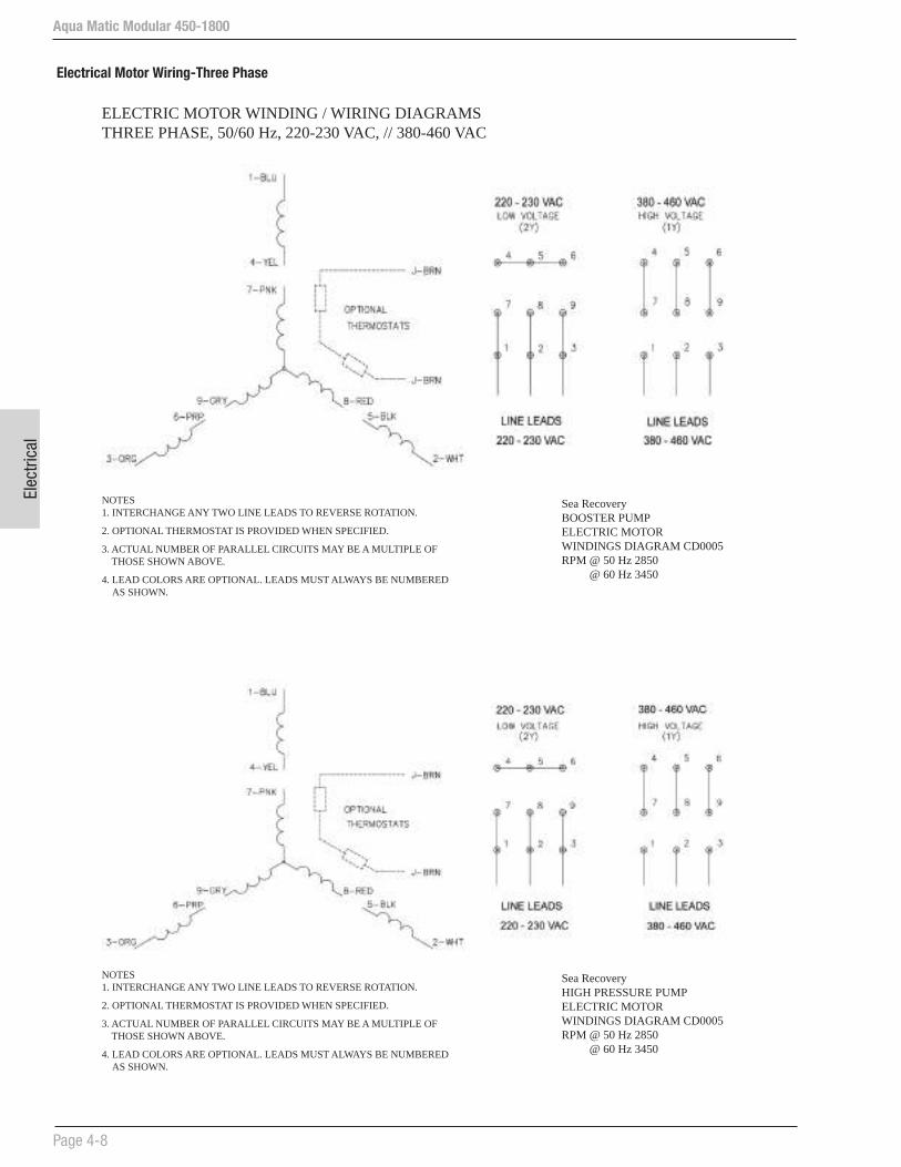
Aqua Matic Modular 450-1800
Page 4-8
Elec
trica
l
Electrical Motor Wiring-Three Phase
Sea Recovery BOOSTER PUMP ELECTRIC MOTORWINDINGS DIAGRAM CD0005RPM @ 50 Hz 2850
@ 60 Hz 3450
NOTES1. INTERCHANGE ANY TWO LINE LEADS TO REVERSE ROTATION.
2. OPTIONAL THERMOSTAT IS PROVIDED WHEN SPECIFIED.
3. ACTUAL NUMBER OF PARALLEL CIRCUITS MAY BE A MULTIPLE OF THOSE SHOWN ABOVE.
4. LEAD COLORS ARE OPTIONAL. LEADS MUST ALWAYS BE NUMBERED AS SHOWN.
ELECTRIC MOTOR WINDING / WIRING DIAGRAMSTHREE PHASE, 50/60 Hz, 220-230 VAC, // 380-460 VAC
Sea Recovery HIGH PRESSURE PUMP ELECTRIC MOTORWINDINGS DIAGRAM CD0005RPM @ 50 Hz 2850
@ 60 Hz 3450
NOTES1. INTERCHANGE ANY TWO LINE LEADS TO REVERSE ROTATION.
2. OPTIONAL THERMOSTAT IS PROVIDED WHEN SPECIFIED.
3. ACTUAL NUMBER OF PARALLEL CIRCUITS MAY BE A MULTIPLE OF THOSE SHOWN ABOVE.
4. LEAD COLORS ARE OPTIONAL. LEADS MUST ALWAYS BE NUMBERED AS SHOWN.

Aqua Matic Modular 450-1800
Page 4-9
Electrical
Three Phase Transformer Wiring
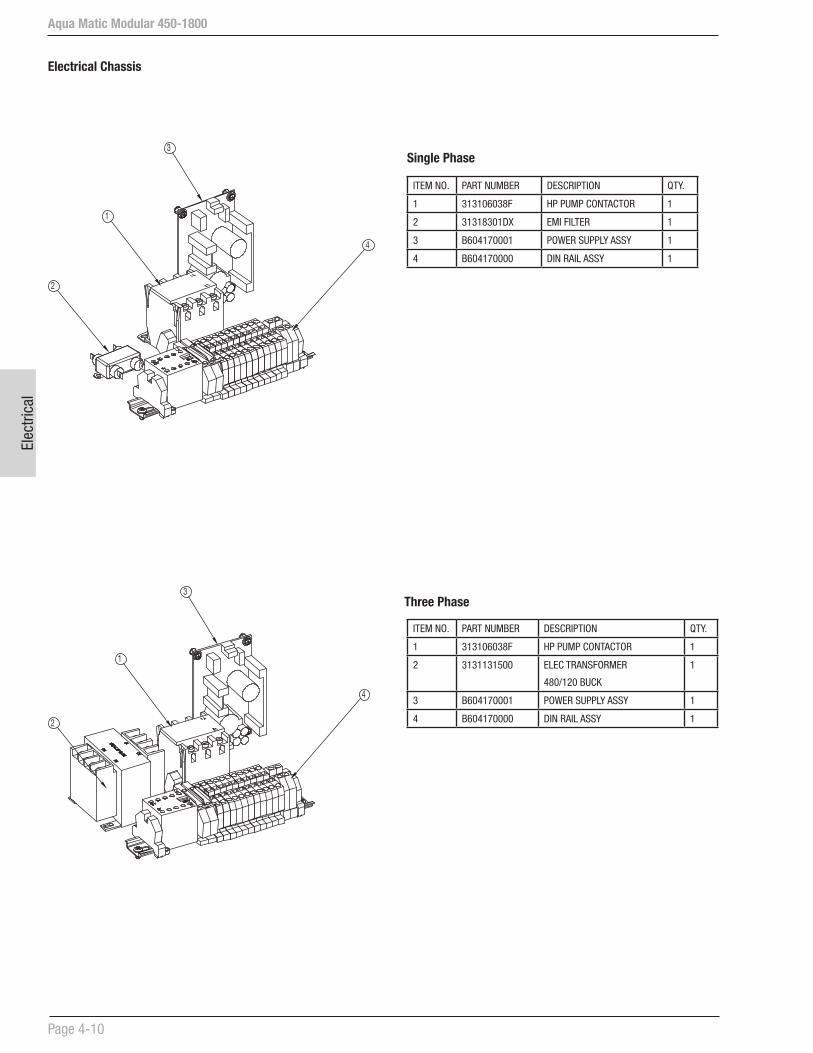
Aqua Matic Modular 450-1800
Page 4-10
Elec
trica
l
Electrical Chassis
Single Phase
Three Phase
3
1
2
4
3
1
2
4
ITEM NO. PART NUMBER DESCRIPTION QTY.
1 313106038F HP PUMP CONTACTOR 1
2 31318301DX EMI FILTER 1
3 B604170001 POWER SUPPLY ASSY 1
4 B604170000 DIN RAIL ASSY 1
ITEM NO. PART NUMBER DESCRIPTION QTY.
1 313106038F HP PUMP CONTACTOR 1
2 3131131500 ELEC TRANSFORMER
480/120 BUCK
1
3 B604170001 POWER SUPPLY ASSY 1
4 B604170000 DIN RAIL ASSY 1

Aqua Matic Modular 450-1800
Page 4-11
Electrical
4.8 MODULAR MODEL WIRING DIAGRAMS
WARNING: ELECTRICAL SHOCK HAZARD. A Volt / Ohm Meter will be necessary. The following installation procedures expose the installer to High Voltage and electrical shock hazard. Only attempt this if you are a qualified electrician and only if surrounding conditions are safe.
NOTE: Refer to Section 11 - Fold Outs (located in the back of this manual) for modular model electrical diagrams.

Aqua Matic Modular 450-1800
Page 4-12
Elec
trica
l
Soft Start Wiring Diagram B596800006
Single Phase Wiring Connections:
If the Motor Soft Start is not already installed, follow these instructions to install it:
1. Disconnect the power source from the System.
2. Open the System or Controller Enclosure cover to access the Electrical Chassis.
3. Connect Motor Soft Start wiring as shown above.
Note: Refer to the wiring diagram for details.
T2-WHTG-GRN
T1-BLK HPPumpM
1
3
2
5
7
6
4
9
11
10
13
12
8T2-WHTT1-BLK
WHT/BLK
L2 (N)RED
WHT/RED
T1-BLK
L1-BLK
T2 (N)-REDT1-BLK
G-GRN
WHT/BLK
L2 (N)-REDL1-BLK
T2 (N)-REDT1-BLK
WHT/RED
FUSES (2A X 2)
T2-RED
SoftStart
T1-B/WT2-W/BG-GRN
T1-BLKT2-REDG-GRN

Aqua Matic Modular 450-1800
Page 4-13
Electrical
3 Phase Wiring Connections:
If the Motor Soft Start is not already installed, follow these instructions to install it:
1. Disconnect the power source from the System.
2. Open the System or Controller Enclosure cover to access the Electrical Chassis.
3. Connect Motor Soft Start wiring as shown above.
Note: Refer to the wiring diagram for details.
HP PumpContactor
T2-W/BT1-B/W
G-GRN
L2-REDL1-BLK
T2-REDT1-BLK
L1L2
L3
T1T2
T3
12
34
56
78
910
1113
14
TB1
T3-BLU
T3-BLU
L3-BLU
12
T2-WHTT1-BLK
T3-BLU
SoftStart
G-GRN

Aqua Matic Modular 450-1800
Page 4-14
Elec
trica
l
This page is intentionally left balnk.

Installation
Aqua Matic Modular 450-1800
Section 5 - INSTALLATION REQUIREMENTS

Inst
alla
tion
InstallationAqua Matic Modular 450-1800
Page 5-1
2. Allow sufficient space between the Inlet Connection and Sea Strainer for the Inline Vacuum/Pressure Gauge, if used.
3. The Sea Strainer is mounted to a flat vertical surface, below water level, between the Inlet Sea Cock Valve or the Inline Vacuum/Pressure Gauge and Rinse Clean Inlet Valve or the Inline Vacuum/Pressure Gauge or Booster Pump. Allow clearance above the bowl to access the mesh screen for cleaning or replacement.
4. The optional Rinse Clean Inlet Valve with attached Rinse Clean Outlet Valve is mounted below water level between the outlet of the Sea Strainer and the Rinse/Clean Bucket or Container and the Inline Vacuum/Pressure Gauge or Booster Pump. Allow access for the operator to reach and turn the valve handles.
5. Allow sufficient space between the Sea Strainer or Inlet Rinse/Clean Valve and Booster Pump for the Inline Vacuum/Pressure Gauge, if used.
6. The Automatic Fresh Water Flush Solenoid Valve is mounted on the Fresh Water Filter Assembly, below water level, before the Booster Pump inlet. Mount the Automatic Fresh Water Flush Check Valve vertical with the arrow pointing UP. Mounting the valve horizontal or with arrow pointing down may cause it to not properly function.
7. The Booster Pump is mounted to a flat horizontal surface using the 4 supplied 1/4x1 SS Type “A” screws. The Booster Pump is mounted below water level to assist priming, and in an accessible location to allow access for maintenance. Mount the Booster Pump in an accessible location for Seal maintenance. Keep the Booster Pump close to the Inlet Thru Hull Sea Cock Valve, Sea Strainer, and Rinse Clean Inlet Valve. If the Booster Pump is mounted Vertical place the Pump Head at the bottom and the electric motor at the top. If the pump head is above the electric motor salt water damage to the electric motor will occur when the pump seal weeps or leaks.
8. Allow sufficient space after the Booster Pump Outlet for the Inline Vacuum/Pressure Gauge, if used. If the Multi Media Filter is installed this Inline Vacuum/Pressure Gauge is not required as the Multi Media Filter includes inlet and outlet pressure gauges.
5 INSTALLATION REQUIREMENTS
NOTE: LAND INSTALLATION Refer to Section 5.7 regarding feed water instructions for land installations. Refer to the rest of this section for installation.
All mounting surfaces must be flat in order to avoid warping of brackets and frames. Any damage caused by attaching the system or its components to an uneven surface is attributed to improper installation, is the liability of the installer, and is not covered by the Sea Recovery warranty. Grind flat or use appropriate shims on uneven surfaces to ensure that mounting of the system components does not cause bending or warping.
Refer to System P&ID in Section 3.
5.1 SYSTEM CONTROL BOXPLACEMENT AND SECURING THE SYSTEM CONTROL BOX
The System Control Box must be placed in a location that allows access for operation and maintenance. Allow access to the bottom side of the control box for electrical wire attachment. Ensure that the Touch Pad is reachable and readable.
The Control Box is mounted in place with 4 supplied rubber isolation mounts. Four threaded bolts and four sheet metal screws are provided for attachment. Set the Control Box in place onto a flat surface and mark the mounting holes.
Move the Control Box out of the way and drill the appropriate hole depending on which hardware will be used. Place the Control Box over the drilled holes and attach the rubber isolation grommet under the frame at each of the 4 mounting holes. Place the mating rubber isolation grommet over the top of the frame hole and attach with the appropriate supplied washers, and bolts or screws.
5.2 COMPONENTSCOMPONENT MOUNTING
Do not connect the water lines or electrical lines to the components until each of the components are in place and secure. After all components are in place and secure visually inspect the layout to ensure that the plumbing hoses and tubes will connect kink free, in short and straight segments, and will avoid heat and abrasions from surrounding surfaces.
1. Attach the supplied Inlet Connection to the Sea Cock Valve and rotate it towards the location of the Sea Strainer Inlet.
Aqua Matic Modular 450-1800
Page 5-2
Inst
alla
tion
9. The optional Plankton Filter (single or double housing version) is mounted to a flat vertical surface using the supplied screws. Allow minimum 4 in. (10 cm) below the bowl, and allow accessibility to the Plankton Filter for mesh screen removal and maintenance. Mount either the Plankton Filter or Multi Media Filter (Installing both is redundant and will lead to line pressure loss) in close proximity to the outlet of the Booster Pump.
10. The optional Multi Media Filter is mounted to a flat horizontal surface using the supplied screws. Maintain an orientation and accessibility that allows the operator to view the pressure gauges, and adjust the valves mounted to the Multi Media Filter. Mount the Multi Media Filter in close proximity to the outlet of the Booster Pump.
Connect the inlet to the Booster Pump or Fresh Water Flush outlet. Connect the oulet to the Prefilter inlet. Connect the Multi Media Filter’s waste discharge fitting to the overboard dump waste fitting. Connect the waste outlet to the Multi Media Filter’s over board dump waste fitting.
Before use, you must place the supplied media, small gravel and fine sand, into the Multi Media Filter. Unscrew the Multi Media fill plug, located on top of the Multi Media Filter lid. Using a funnel, pour in approximately 15 lbs. (7 kg) of small gravel (1/8”x1/4”), then pour in approximately 26 lbs. (12 kg) of #20 silica sand. The silica sand must always go on top of the gravel. Clean the fill plug female threads of all debris and replace lid with a wrench, lightly tightened.
NOTE: The Multi Media Filter must be back washed prior to use to avoid prefilter and RO Membrane Element fouling. (Refer to Commisioning, Section 6)
11. Allow sufficient space after the Plankton Filter Outlet for the Inline Vacuum/Pressure Gauge, if used. If the Multi Media Filter is installed this Inline Vacuum/Pressure Gauge is not required.
12. Prefilter. The 10 in. (25.4 cm) Dual Prefilters and the Commercial Prefilter serve the same function. Use either the 10 in. (25.4 cm) Dual Prefilters or the Commercial Prefilter. Do not use both. Using both is redundant and will lead to line pressure loss.
The Dual Prefilters are mounted to a flat vertical surface. Allow minimum 4 in. (10 cm) below the bowl, and allow accessibility to the Filters for element removal and maintenance.
Either install the Dual Prefilters OR Commercial Prefilter (Installing both will lead to line pressure loss).
The optional Commercial Prefilter replaces the 10 in. (25.4 cm) Dual Prefilters. The Commercial Prefilter is mounted to a flat horizontal surface using the supplied screws. Maintain an orientation and accessibility that allows the operator access to remove the filter element for maintenance. Allow minimum 12 in. (30.5 cm) above the top of the housing for filter element removal. Mount the Commercial Prefilter in close proximity to the outlet of the Booster Pump and the System frame. The commercial prefilter is plumbed as per the raised arrow and Inlet & Outlet letters molded into the filter housing. The correct water flow enters the outer surface of the filter element and migrates to the center core. Refer to PAGE 5-4, fig. 5b
13. Allow sufficient space after the Commercial Prefilter for the Inline Vacuum/Pressure Gauge, if used.
14. The Oil/Water Separator is mounted to a flat horizontal surface using supplied screws. Maintain an orientation and accessibility that allows the operator access to remove the filter element for maintenance. Allow minimum 12 in. (30.5 cm) above the top of the housing for filter element removal. Mount the Oil/Water Separator in close proximity to the outlet of the Booster Pump and the System frame. Inlet and Outlet labels (stickers) indicate the correct plumbing for the Oil/Water Separator. Follow the stickers, not the molded arrow and lettering. Refer to PAGE 5-3., fig. 5b
WARNING NOTE (Refer to pg. 5-3, fig. 5b.): The Oil/Water Separator utilizes the same filter housing as the Commercial Prefilter.
Filling plug
Inlet of Multi Media Filter from Booster Pump outlet -or-Fresh Water Flush outlet
Outlet of Multi Media Filter to Prefilter Inlet
Waste discharge of Multi Media Filter to Multi Media Filter waste overboard dump fitting
Figure 5a: Multi Media Filter

InstallationAqua Matic Modular 450-1800
Page 5-3
Figure 5b: Follow the labeling - NOT the molded arrows and lettering
Aqua Matic Modular 450-1800
Page 5-4
Inst
alla
tion
15. Pressure Differential Transducer. The optional Pressure Differential Transducer threads into the center port of the Low Pressure Transducer Manifold.
CAUTION: Take care to NOT cross the fine female threads in the manifold.
Thread in clockwise finger tight. Using a wrench tighten an additional 45 degrees. DO NOT OVER TIGHTEN.OVER TIGHTENING WILL STRIP THE MANIFOLD FEMALE THREADS. Using the supplied 1/4 in. (6.35 mm) O.D. tubing connect the center Pressure Differential Transducer Tube Fitting to the T-Connector Pressure Pick-Up or to the Pressure Pick Up port of the respective Prefiltration component. Refer to the various Piping and Interconnect Diagrams Illustrated in this Section 3.
16. The HP Pump is mounted to a flat horizontal surface using the 4 supplied 5/16-18x3/4 SS Hex bolts, nuts and washer. The HP Pump is mounted in an accessible location to allow access for maintenance.
Set the HP Pump in place onto a flat surface and mark the mounting holes.
Move the HP Pump out of the way and drill the appropriate hole depending on which hardware will be used. Place the HP Pump over the drilled holes and attach the rubber isolation grommet under the plate at each of the 4 mounting holes.
17. RO Membrane Presure Vessels must be mounted on a flat or vertical surface close to the HP Pump. If possible allow 27-47 in. (68.6-119.4 cm) clearance at the ends for RO Membrane maintenance.
The Pressure Vessel assembly can be removed entirely from surface for maintenance.
18. UV Sterilizer Installation. The Ultra Violet Sterilizer should be mounted on a flat horizontal or vertical wall. Refer to Section 5.8 for installation details.
19. The Fresh Water Flush Carbon Filter, with attached Fresh Water Flush 2-Way Solenoid Valve and Fresh Water Flush Check Valve is mounted to a flat vertical surface in an accessible location for filter element changing. Choose a location between the Automatic Fresh Water Flush Check Valve and a pressurized line from the boat’s fresh water pressure system.
CAUTION: In order to provide the required flow of water to the Aqua Matic System during the Fresh Water Flush cycle, the Boat or Home’s fresh water pressure system must deliver minimum 1 U.S. Gallons (3.8 Liters) Per Minute at minimum 25 PSI and maximum 60 PSI (minimum 172 kPa and maximum 414 kPa).
TUBING AND HOSE PRECAUTIONS
TUBE FITTING CONNECTIONS ASSEMBLY
a. Cut tube end square and clean.
b. Loosen nut on fitting three turns.
c. Insert tube into fitting until it bottoms.
d. Loosen nut completely and remove tube with attached parts from body.
e. Check to ensure that the O-Ring is seated onto the tube under the spacer (and not pinched into the body).
f. Insert tube with attached parts into the body and tighten nut finger tight.
CAUTION (Refer to fig. 5c, pg 5-5): Always allow slack in all tube and hose lines. Never cause the tube or hose to immediately bend from the fitting. Allow the line to enter or leave from the fitting in a straight manner for several inches to ensure proper connection, to relieve stress to the fitting and tube or hose, and to allow ease of detachment and reattachment during maintenance or repair.
However, the Oil/Water Separator is plumbed opposite of (backwards from) the Commercial Prefilter. The standard filter housings have raised arrows and lettering molded indicating correct flow for the Commercial Prefilter. These markings are INCORRECT for the Oil/Water Separator. The OIl/Water Separator’s correct water flow enters the center core of the filter element and migrates to the outer surface of the filter element.
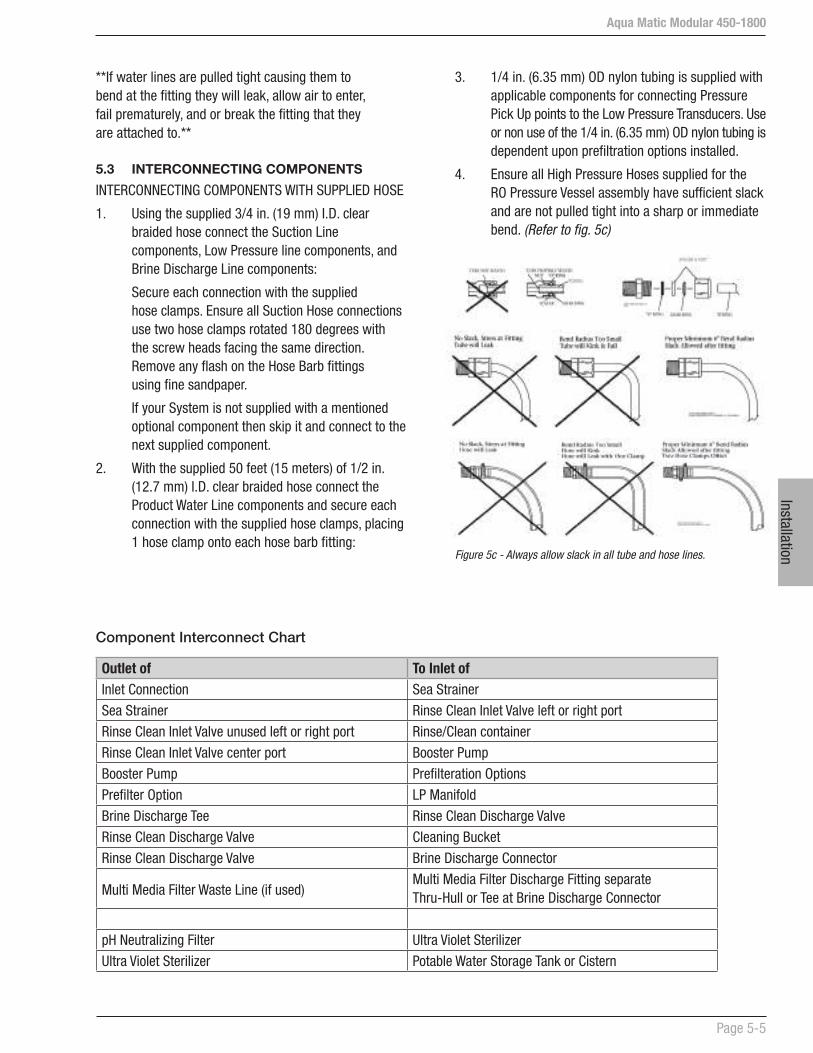
InstallationAqua Matic Modular 450-1800
Page 5-5
**If water lines are pulled tight causing them to bend at the fitting they will leak, allow air to enter, fail prematurely, and or break the fitting that they are attached to.**
5.3 INTERCONNECTING COMPONENTS
INTERCONNECTING COMPONENTS WITH SUPPLIED HOSE
1. Using the supplied 3/4 in. (19 mm) I.D. clear braided hose connect the Suction Line components, Low Pressure line components, and Brine Discharge Line components:
Secure each connection with the supplied hose clamps. Ensure all Suction Hose connections use two hose clamps rotated 180 degrees with the screw heads facing the same direction. Remove any flash on the Hose Barb fittings using fine sandpaper.
If your System is not supplied with a mentioned optional component then skip it and connect to the next supplied component.
2. With the supplied 50 feet (15 meters) of 1/2 in. (12.7 mm) I.D. clear braided hose connect the Product Water Line components and secure each connection with the supplied hose clamps, placing 1 hose clamp onto each hose barb fitting:
Outlet of To Inlet ofInlet Connection Sea Strainer
Sea Strainer Rinse Clean Inlet Valve left or right port
Rinse Clean Inlet Valve unused left or right port Rinse/Clean container
Rinse Clean Inlet Valve center port Booster Pump
Booster Pump Prefilteration Options
Prefilter Option LP Manifold
Brine Discharge Tee Rinse Clean Discharge Valve
Rinse Clean Discharge Valve Cleaning Bucket
Rinse Clean Discharge Valve Brine Discharge Connector
Multi Media Filter Waste Line (if used)Multi Media Filter Discharge Fitting separate Thru-Hull or Tee at Brine Discharge Connector
pH Neutralizing Filter Ultra Violet Sterilizer
Ultra Violet Sterilizer Potable Water Storage Tank or Cistern
Component Interconnect Chart
Figure 5c - Always allow slack in all tube and hose lines.
3. 1/4 in. (6.35 mm) OD nylon tubing is supplied with applicable components for connecting Pressure Pick Up points to the Low Pressure Transducers. Use or non use of the 1/4 in. (6.35 mm) OD nylon tubing is dependent upon prefiltration options installed.
4. Ensure all High Pressure Hoses supplied for the RO Pressure Vessel assembly have sufficient slack and are not pulled tight into a sharp or immediate bend. (Refer to fig. 5c)

Aqua Matic Modular 450-1800
Page 5-6
Inst
alla
tion
5.4 WATER TANK
CUSTOMER SUPPLIED FRESH WATER TANK, HIGH AND LOW LEVEL SWITCHES, AND ALARM
Not Numbered on the Piping and Interconnect Diagram. Installed inside the Fresh Water Tank.
These two tank level switches are not necessary for operation of the System. They do add additional features to the Automatic mode of the System. The choice of make, model, and style are left up to the Installer or Owner. They must meet the electrical requirement and operation as explained below.
The customer may also connect an external alarm to the System which will alert the operator that they system has shut down.
Fresh Water Tank Low Level Switch ** owner/installer supplied provides an optional feature to the System Control Logic that works in conjunction with the Automatic Fresh Water Flush option.
When installed and connected to the Main Printed Circuit Board, the Fresh Water Tank Low Level Switch must be connected as a N.O. (Normally Open) 1PST (One Pole Single Throw) switch.
When the Fresh Water Tank is empty the switch is Open. As water rises a few inches in the tank the switch Closes. This informs the System Control Logic that there is sufficient Fresh Water to perform the Automatic Fresh Water Flush Cycle.
Fresh Water Tank High Level Switch ** owner/installer supplied provides an optional feature to the System Control Logic that allows the System to shut off automatically when the Fresh Water Tank is full, when the System is operated in the Automatic mode. Additionally, the System will not start in the Automatic mode when the Fresh Water Tank High Level Switch signals the System Control Logic that the Fresh Water Tank is full.
When installed and connected to the Main Printed Circuit Board, the Fresh Water Tank High Level Switch must be connected as a N.C. (Normally Closed) 1PST (One Pole Single Throw) switch.
When the Fresh Water Tank is several inches below the full mark the switch is Closed. As water rises and reaches the top of the full mark the switch Opens. This informs the System Control Logic that the Fresh Water Tank is full, the System will shut down if operating in the Automatic mode, and the System will not start in the Automatic mode.
If operation of the System is desired when the Fresh Water Tank Switch signals the System Control Logic that the Fresh Water Tank is full then the System may be operated in the Manual mode.
Alarm ** owner/installer supplied provides an optional feature to the System Control Logic that audibly or visually signals the operator that the System has stopped operating.
The output of this alarm circuit form the Main Printed Circuit Board is 12 VDC with MAXIMUM allowable current consumption of 1 (one) Ampere.
This alarm will signal if a fault occurs. It will not signal with a normal shut down that was not associated with a fault.
5.5 REMOTE TOUCH SCREEN
PLACEMENT AND SECURING THE REMOTE TOUCH SCREEN ENCLOSURE ASSEMBLY
The Remote Touch Screen Enclosure Assembly is supplied with a 80 ft. (24.4 m) long NMEA 200 cable for connection to the Main Control Panel.
Place and install the Remote Touch Screen Enclosure in a location that is:
1. Away from water lines and hoses
2. Away from locations subject to water spray
3. In an accessible and viewable location
4. Within 80 ft. (24.4 m) of the Main Control Panel
5.6 ELECTRICAL CONNECTIONS
Refer to the electrical diagram in Section 4.
CAUTION: The Reverse Osmosis Membrane Element(s) must be kept wet else severe loss of production will occur. Refer to Section 7 for further information and instructions.
5.7 LAND FEED WATER PICK-UP
LAND INSTALLATION FEED WATER PICK-UP INFORMATION
Refer to the illustrations on the next page.
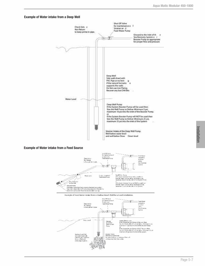
InstallationAqua Matic Modular 450-1800
Page 5-7
Example of Water intake from a Deep Well
Example of Water intake from a Feed Source

Aqua Matic Modular 450-1800
Page 5-8
Inst
alla
tion
2. Wrap ¼ in (6.35 mm) wide PTFE tape 2 to 3 turns counter-clockwise around the male threads of the ¼ in (6.35 mm) fitting. Do not wrap tape around the first thread.
3. Screw the fitting into cylinder ports to finger tight position to achieve desired alignment.
4. Do not back-off fitting. Do not over-tighten fitting. Over-tightening could strip the fitting threads and cause leak.
Install Quartz Sleeve
Perform this procedure only when water piping for UV unit is in place and ready for service.
1. Visually inspect quartz sleeve for cracks and damages.
2. Remove the four screws holding the ballast box cover and remove the cover.
3. Remove the rubber boot. pull out the 4-point lamp connector.
4. Remove the compression nuts.
5. Insert the close-end of the quartz sleeve into the cylinder through the ballast box pass-thru.
6. Leave a ½ in (12.7 mm) of the quartz sleeve to expose on the viewport pass-thru.
5.8 UV STERILIZER INSTALLATION
The SP Series UV unit is shipped with the UV lamp, quartz sleeve, fittings, and O-rings and need to be assembled before the UV unit can be used.
1. Install the UV unit in a sheltered, well ventilated area.
2. Install the UV unit as close as possible to the point-of-use to avoid potential contamination discharge from pipes, fittings, etc.
3. The UV unit should be mounted on stable support to avoid straining or warping. Allow sufficient clearance around the unit for servicing.
4. Verify the location is free from vibration.
5. All UV units are rated for maximum operating pressure at 50 psig (8.24 bar).
6. The UV unit must be properly grounded for safe and proper operation. Failure to properly ground the UV unit automatically voids all unit warranty.
7. Line voltage must be within 10.56V to 16.50V. Voltage outside the range will compromise the performance of the UV unit.
Plumbing Requirements
All piping, tubes and hoses leading to the UV unit connection points must be leak-free before the UV unit can be installed.
NOTE: The UV unit may be installed horizontally or vertically. For vertical installation, make sure the inlet port is positioned at the bottom.
Installation Procedure
NOTE: Do not assemble or install damaged parts. Quartz sleeve and UV lamp are fragile and must be handled with care.
Install Fittings
Perform this procedure to prepare the UV unit for installation.
1. Inspect each port and fitting to ensure threads are free of dirt, burrs, and excessive nicks. If threads are badly nicked, replace the fitting.

InstallationAqua Matic Modular 450-1800
Page 5-9
NOTE! To remove tube from fitting, first remove the C-clamp then push fitting sleeve down. Once the fitting sleeve is down, pull the tube out of the fitting.
Install Ultraviolet Lamp
Perform this procedure only after the quartz sleeve installation and leak-tests are completed successfully
1. Connect the UV lamp to the 4-point receptacle. If the lamp is not installed properly, lamp breakage will occur.
2. Insert lamp into quartz sleeve through compression nut pass-thu.
3. Install rubber boot over compression nut.
4. Connect unit power cable to power source.
5. Tighten the 4 screws to secure ballast box cover.
6. Turn ON the power to the unit.
7. Verify UV lamp operation from the viewport.
8. Allow one minute for the UV lamp to warm up prior to flowing water through the UV unit.
CAUTION! Use the viewport to verify the proper operation of the UV lamp.
7. Lubricate the tips of the quartz sleeve with clean water and insert new O-ring. Ensure the O-ring has all-round contact with the cylinder pass-thru.
8. Tighten the compression nut while making sure the nut does not contact the quartz sleeve. Adjust O-ring position as necessary. The compression nut should be snug and tight, not over-torque.
9. Repeat Step 7 and 8 on the ballast box compression nut.
Connect Plumbing
Tube or hose ends must be cut squared and clean; must have no rough edges. The quick fit elbow fitting has a C-clamp that will lock the tube in place once inserted.
1. Insert the supply pipe into one cylinder port and label the port “Inlet”.
2. Insert the temporary pipe into the other cylinder port to direct water into a container.
3. Slowly fill the cylinder with water and flush cylinder for 1 minute.
4. Remove temporary pipe and insert the return pipe into the cylinder port and label the port “Outlet”.
5. Slowly pressurize the UV unit by filling the cylinder with water while checking for leaks.
6. If leaks are found on the compression nuts, depressurize the unit and slightly tighten the leaking compression nut.
7. Retest until a leak-free installation is verified.
8. Once UV unit is leak-free, the quartz sleeve installation is complete and the UV lamp can be installed.
Aqua Matic Modular 450-1800
Page 5-10
Inst
alla
tion
CAUTION! Rapid successive cycling of the power to the ballast can cause premature failure of the unit.
CAUTION! Prior to energizing the lamp, make sure there is no water leaking from the quartz sleeve compression nuts.
Mounting the Unit
Once the UV unit is assembled and tested successfully, it can be mounted onto its permanent operational location. The unit must be mounted in a manner that will prevent excessive vibration and warping which will damage the quartz sleeve.
Operational Guidelines
a) Release the pressure in the UV treatment chamber before breaking the compression nut seals.
b) Disconnect all power to the UV unit before servicing.
c) Do not allow the inlet water temperature to drop below 35ºF (2ºC).
d) Do not allow the flow rate to exceed 2 GPM (7.5 LPM).
e) Do not cycle the UV unit more than 3 “ON/OFF” cycles in a 24-hour period.
f) Ensure all plumbing connections are tightly sealed before applying pressure.
g) Before connecting the return tube, flush the unit to rinse out any debris left from the installation process.
WARNING! UV LIGHT EXPOSURE CAN SEVERELY BURN AND DAMAGE EYES AND SKIN.
WARNING! DO NOT look at the blue UV light. DO NOT operate the UV lamp outside of the UV treatment chamber.
CAUTION! The unit operates on high voltage and must be serviced by qualified personnel only.
CAUTION! Standard flow rate are based on water temperature 35ºF to 100ºF (2ºC to 38ºC). If the inlet water temperature exceeds 100ºF (38ºC), please contact your local CSR.
CAUTION! Cycling more than 3 cycles will reduce the end-of-life (EOL) output and/or cause premature lamp failure.

Comm
issioning
Aqua Matic Modular 450-1800
Section 6 - COMMISSIONING

Com
mis
sion
ing

Aqua Matic Modular 450-1800
Page 6-1
Comm
issioning
If the Reverse Osmosis Membrane Element has been installed, there will be a Reverse Osmosis Membrane Element Serial Number tag, attached to the High Pressure Vessel.
If the R.O. Membrane Element Serial Number tag is missing or does not contain a serial number and date, then immediately contact the company that sold the system to you, the installer, or Sea Recovery.
WARNING! DO NOT attempt to operate the system without a Reverse Osmosis Membrane Element installed in the system otherwise extensive damage will result.
WARNING! Damage caused to the system due to operation of the System without an R.O. Membrane Element correctly installed is the liability of the installer and the operator.
6.3. SETUP CONTROLLER
The controller is set by Sea Recovery prior to shipping based on the features and optional equipment that shipped with the System at the time of ordering.
Addition of the Fresh Water Flush to the System after it has shipped from Sea Recovery will require new set up of the computer logic.
Addition of, removal of, or changes in the length of the R.O. Membrane / Pressure Vessel Assembly will require control logic setup. Refer to the Programming Kit manual.
6 COMMISSIONING
COMMISSIONING NOTES
These Commissioning instructions must be carried out for initial start-up of a NEW system.
Failure to follow these instructions will lead to system failure and cause damage to components.
6.1 CHECK INSTALLATION
Ensure that the installation has been properly performed. Do not rely on the installer’s word, do not assume the System has been installed correctly.
WARNING: Damage caused to the system due to operation of an improperly installed system is the liability of the installer and the operator.
Check each water connection to the system to ensure that the installer has properly connected and properly routed each tube. Improper routing and any blockage in any line causes damage to the system. Improperly connected or loose connected lines resulting in leaks causing damage is the liability of the installer and the operator, and is not covered by the Sea Recovery warranty.
Do not assume and do not rely on the installer’s word; check it yourself.
Make sure that the Electrical Power Source, boat’s circuit breaker to the system, is switched “OFF”.
Open the Electrical Control Box and check all electrical and electronic connections for proper wiring and attachment.
After checking all wiring for correct and tight connection, close the Electrical Control Box.
Switch the Electrical Power Source, boat’s circuit breaker to the system, to the “ON” position.
6.2 CHECK R.O. MEMBRANE
Check to ensure that the Reverse Osmosis Membrane Elements are installed within the Pressure Vessels.
CAUTION: Some systems are shipped WITHOUT the Reverse Osmosis Membrane Element. This is to accommodate Boat Builders that install the system well in advance of commissioning the System.

Aqua Matic Modular 450-1800
Page 6-2
Com
mis
sion
ing
6.4 CHECK SYSTEM MANUALLY
Refer to the P&ID in Section 3.
1. Ensure that the manual By-Pass lever on the 3-Way Product Water Diversion Valve is positioned outward (away from the coil body).
2. Open any auxiliary valve within the incoming Feed Line, Outgoing Brine Discharge Line, and Outgoing Product Water Line.
WARNING: If any auxiliary valve is installed in these lines, it will damage the System if left closed during starting and/or operation of the system. The resulting damage is the liability of the operator.
3. Position Rinse Clean Inlet Valve to normal operation towards the Sea Restrainer.
4. Position Rinse Clean Outlet Valve to normal operation towards the Thru Hull Discharge Fitting.
d) PRESSURE Manually control the system pressure by increasing or decreasing the setpoint of the back pressure regulator.
2. DISPLAY Changes the color contrast of the touch screen for better viewing.
3. ACCEPTED SALINITY LEVEL Changes the accepted salinity level by adjusting the PPM level.
4. BACK WASH TIME Changes the interval for automatic back washing by adjusting the number of days.
5. LANGUAGE Changes the current language used on the controller by selecting new language option.
6. UNIT Toggles the measurement standards between U.S. Standards and Metric Standards
Pressure: U.S. Standard = PSI (Pounds Per square Inch); Metric Standard = kPa (kilo Pasquel)
Flow: U.S. Standard = GPM (Gallons Per Minute) or GPH (Gallons Per Hour); Metric Standard = LPM (Liters Per Minute) or LPH (Liters Per Hour).
A. FEATURES PROGRAMMABLE BY OPERATOR
The following is an explanation of features that are programmable by the operator. It is required that each feature be set properly in order to gain maximum performance of the System.
Only preinstalled features will be displayed on this screen.
1. MANUAL MODE Enable user to control the Booster Pump, HP Pump, Diversion Valve and Pressure.
a) BOOSTER PUMP Manually start and stop the Booster Pump.
b) HIGH PRESSURE PUMP Manually start and stop the HP Pump.
c) DIVERSION VALVE SET POINT Manually energize the 3-Way Product Water Diversion Valve at a specific product water quality, in PPM (Parts Per Million). The factory setting is 800 PPM TDS (eight hundred Parts Per Million Total Dissolved Solids expressed as NaCl [sodium chloride - salt]).
Aqua Matic Modular 450-1800
Page 6-3
Comm
issioning
5. Check all filter housings to ensure that they contain the proper filter element:
a) Sea Strainer check for monel screen.
b) Plankton Filter if installed check for monel fine mesh screen filter element.
c) Multi Media Filter if installed check for media (#20 silica sand).
d) Dual Prefilter or Commercial Prefilter check for pleated cartridge filter elements
e) Oil/water Separator check for Oil/water Separator filter element
f ) R.O. Membrane(s) check for Sea Recovery Serial Number and Date on the label attached to each pressure vessel.
g) Charcoal Filter check for charcoal filter element
h) pH Neutralizer check for pH Neutralizer cartridge
i ) Fresh Water Flush Carbon Filter check for Carbon element.
6. Function Tests of Electric Components:
PRIOR TO ASSUMING THAT AN ELECTRICAL COMPONENT IS BROKEN OR NON FUNCTIONAL PERFORM A FUNCTION TEST TO DETERMINE IF IT IS OPERABLE OR NOT.
Function Tests should be performed manually as part of the commissioning procedure.
Booster Pump Electric Motor•
High Pressure Pump Electric Motor•
Diversion Valve energize solenoid•
Fresh Water Flush Valve energize solenoid•
• Back Pressure Regulator Electric Motor Actuator
UV Sterilizer Ballast and Lamp•
a) Electric Motor Rotational Check: Ask an assistant to view the fan section of the Booster Pump Motor and High Pressure Pump Motor while you “Jog” each of these electric motors. Rotation is clockwise when viewing the back of the electric motor (fan), counter clock wise when viewing the front of the pump.
b) Check the function of the following:
DIVERSION VALVE: • 3-Way Product Diversion Valve Solenoid
will energize momentarily. The valve should click when repositioning.
FWF VALVE: Fresh Water Flush Solenoid • Valve will actuate to the Fresh Water Flush position. Pressing the switch a second time will cause the Fresh Water Flush Solenoid Valve to revert to the Normal Feed position. The valve should click when repositioning.
BPR IN: Back Pressure Regulator Motor • Actuator will rotate clock wise momentarily. The actuator motor will not rotate in if the valve is less than one turn open.
BPR OUT: Back Pressure Regulator • Motor Actuator will rotate counter clock wise momentarily. The actuator motor will not rotate out if the valve is greater than 8 turns open.
UV STERILIZER: UV Sterilizer will flicker. • Check for illumination from the UV Sterilizer viewport.
c) Correct any abnormalities.
7. Prime the System. In order to save time and make the initial start easy, when starting the System for the first time, the feed water lines and each component in the prefiltration section should be filled with either feed water or fresh water. This will prime the feed water section including the Booster Pump so that it will be able to pick up and continue delivering feed water.
6.5 OPERATION NOTES
BEFORE starting the System in auto mode be prepared for the following sequence. After the System has been started the following will occur:
1. Booster Pump electric motor will start.
2. Low Pressure Transducers will signal the System Control Logic which will look for adequate feed water pressure from the Booster Pump.
3. After 20 seconds, the High Pressure Pump electric motor will start and a screen will indicate that it has started.
4. Feed Water Flow Meter will signal the System Control Logic which will look for adequate feed water flow through the System.
5. After 20 seconds, the Automatic Back Pressure Regulator will rotate clockwise to build up operating pressure.

Aqua Matic Modular 450-1800
Page 6-4
Com
mis
sion
ing
6. Product Water Flow Meter will register product water flow, as operating pressure exceeds the osmotic pressure of the feed water. Product Water Flow will take priority to inform the control logic to increase or decrease operating pressure in order to maintain the product water flow specification.
7. Salinity Probe will register the quality of the Product Water. When the salinity of the Product Water lowers to the set point the UV Sterilizer will energize if installed.
8. The 3-Way Product Water Diversion Valve will energize sending the Product Water to the Post Filtration section. This may take up to 30 minutes as the Product Water flushes storage chemical from the System.
9. Feed Pressure, Feed Flow, Operating Pressure, Brine Flow, Product Flow, and Product Salinity are all being monitored and the values of these readings cause the System Control Logic to perform various tasks to maintain proper functioning of the System.
10. The System may be manually stopped, or it may be programmed to stop at a given volume of Product Water production.
11. When the System is signaled to perform a non-emergency stop the Automatic Back Pressure Regulator Valve will rotate counter clockwise to lower operating pressure.
12. The 3-Way Product Water Diversion Valve will revert to unpotable water.
13. The UV Sterilizer will stop.
14. The High Pressure Pump will stop.
15. The Booster Pump will stop.
16. If the System does not include the Automatic Fresh Water Flush option this ends the stop sequence.
17. If the System includes the Automatic Fresh Water Flush the Automatic Fresh Water Flush Valve will energize to Fresh Water.
18. After 7 to 15 minutes the Fresh Water Flush Valve will de-energize.
19. The Stop sequence is complete.
20. The System will go to a Fresh Water Flush Stand-by mode and count down the days until the next automatic Fresh Water Flush Cycle. The Fresh Water Flush Cycle will automatically initiate until canceled or power is disconnected from the System.
6.6 INITIAL STARTUP
6.6.1. POSITION SYSTEM VALVES
VALVE POSITION
Inlet Sea Cock Valve FULL OPEN
Rinse Clean Inlet Valve FROM SEA STRAINER TO FRESH WATER FLUSH VALVE
Rinse Clean Outlet Valve FROM BRINE DISCHARGE OF SYSTEM TO THRU HULL DISCHARGE FITTING
Multi Media Filter Valves NORMAL OPERATION
ANY auxiliary valve in the Feed Line, Brine Discharge Line, or Product Water Line
FULL OPEN
WARNING: If any auxiliary valve is installed in these lines, it will damage the System if left closed during starting and/or operation of the system. The resulting damage to the system is attributed to improper installation, is the liability of the operator, and is not covered by the Sea Recovery warranty.
MULTI MEDIA FILTER BACKWASH AND RINSE:
If the System is equipped with a Multi Media Filter it must be back washed and rinsed. New gravel and sand contain fines that must be backwashed from the multi media filter prior to operating the System.
1. Open the Inlet Sea Cock Valve.
2. Position the Rinse Clean Inlet Valve, to the normal operating position towards the Sea Strainer.
3. Position the Rinse Clean Outlet Valve, to the normal operating position towards the Multi Media Filter Brine Discharge Thru-Hull Fitting.
4. Position the Multi Media Filter valves to Backwash.
5. Set the controller into the Manual mode of operation, and operate only the Booster Pump.
6. After 10 minutes of back washing, stop the Booster Pump.
7. Position the Multi Media Filter Valves to Rinse.
8. In the Manual mode of operation, operate only the Booster Pump.
9. After 5 minutes of Rinsing, stop the Booster Pump.
10. Position the Multi Media Filter Valves to Normal Operation.

Aqua Matic Modular 450-1800
Page 6-5
Comm
issioning
6.6.3. START THE SYSTEM
A. AUTOMATIC MODE
The Auto Mode is highly recommended for users and owners. OPERATION IN AUTO MODE WITHOUT THE FRESH WATER FLUSH OPTION INSTALL AND SET:
1. From the default screen, touch the Start button.
2. After the System has started, although the system is producing “Product Water”, the Product Water may not be “Potable” for up to 30 minutes. The salinity of the Product Water diminishes gradually, until it reaches the preset setting. When the Product Water is Potable, the UV Sterilizer energizes. The Potable Water is then diverted by the 3-way Product Water Diversion Valve to the “Potable” (good water) position and into the Post Filtration components onward to the Storage Tank.
All System readings, pressures, flows, and salinity will be displayed on the Touch Screen.
3. If any abnormality develops, touch the STOP button and correct the problem.
4. During operation, check for:
a) A constant feed water flow.
b) A consistent system pressure.
c) Leaks in the system.
d) Abnormal noises or other occurrences.
5. Proceed to Log System Readings.
B. MANUAL MODE
The Manual Mode is intended for Sea Recovery technicians for setup and configuration purposes.
NOTE: The Remote Touch Screen will be blocked during operation in the Manual Mode.
CAUTION: When the System is operated in the MANUAL Mode Safety features will still be controlled by the System Logic, however AUTOMATED features will not be controlled by the System Logic and must be controlled by the operator.
1. From the default screen, touch the SETUP tab.
2. On the next screen, touch the Acceptable Salinity Level button.
6.6.2. APPLY POWER TO THE SYSTEM
a) Switch the Electrical Power Source, boat or home’s circuit breaker to the system “ON”.
b) All Operating Screens WILL NOT include the Automatic Fresh Water Flush components if the Fresh Water Flush Option is not installed and the control logic has been informed that the Fresh Water Flush Option is not installed.
c) After the control logic has initiated itself, the default screen will appear indicating that the System is ready to Start (fig. 6a).
Figure 6e: Valves positioned for Media Filter Rinse
Figure 6f: Valves positioned for Normal Operation
Figure 6d: Valves positioned for Media Filter Backwash
Fig.
6a:
Def
ault
scre
en

Aqua Matic Modular 450-1800
Page 6-6
Com
mis
sion
ing
6.7 WARNINGS AND CAUTIONS
NEW SYSTEMS
A new System may take up to 30 minutes to purge the R.O. Membrane Element of the storage chemical and produce Potable Water. Even after the storage chemical
6.6.5. SHUTDOWN THE SYSTEM
A. AUTOMATIC MODE
1. From the default screen, touch the STOP button.
If the Automatic Fresh Water Flush option is not installed the shut down sequence is complete:
If the Automatic Fresh Water Flush option is installed the Automatic Fresh Water Flush cycle will start:
B. MANUAL MODE
This mode of operation is intended for SRC technicians for setup and configuration purposes.
1. From the Manual Mode screen, reduce the Pressure to 0 psi using the - (negative) button.
2. Touch the Diversion Valve button to de-activate.
3. Touch the HP Pump STOP button.
4. Touch the Booster Pump STOP button.
The Automated Fresh Water Flush will NOT activate automatically because operation during the Manual Mode deactivates all Automated features. In order to perform a Fresh Water Flush follow the directions in Section 7:
The Automated Fresh Water Flush Cycle will not be performed until the System is operated in the Automatic Mode.
BOAT SAFETY WARNING: The Inlet Thru-Hull Sea Cock Valve is in the Open position. It is recommended for the safety of the boat to close the Sea Cock Valve when ever the System is not in use. This will protect the boat from water flooding should a hose or component fail.
AUTOMATIC OPERATION WARNING: If the Automatic Fresh Water Flush option is installed and if the System Control Logic has been set to perform Automatic Fresh Water Flushing, the Touch Pad will show the operator when this automatic cycle will be performed.
3. On the Salinity Level screen, adjust the salinity to desired level (188 to 370 PPM) then touch the SETUP button.
4. On the next screen, touch the Manual Mode button.
5. On the next screen, touch the Booster Pump START button then wait 5 seconds for booster pump to stabilize.
6. Touch the HP Pump START button.
7. Slowly increase the High Pressure level meter until the System product flow rate if reached.
PRODUCT SALINITY (RED) simply means that the dissolved solids in the Product Water have not yet decreased to acceptable level.
Although the system is producing “Product Water”, the Product Water may not be “Potable” for up to 30 minutes. The salinity of the Product Water diminishes gradually, until it reaches the acceptable level or lower.
PRODUCT SALINITY (GREEN) simply means that the dissolved solids in the Product Water have reached the acceptable level and the Diversion Valve can be activated.
8. Activate the Diversion Valve.
Touch the Diversion Valve button. This will cause the UV Sterilizer to energize, and the 3-Way Product Water Diversion Valve to energize and divert “Potable” (good water) into the Post Filtration and onward to the Ship’s Storage Tank.
All System readings, pressures, flows, and salinity will be displayed on the Main Touch Screen.
If any abnormality develops, touch the STOP button on the top right corner of the screen. A warning screen will display. Correct the problem then repeat Step 1-8.
9. Check for:
a) A constant feed water flow.
b) A consistent system pressure.
c) Leaks in the system.
d) Abnormal noises or other occurrences.
6.6.4. LOG SYSTEM READINGS
1. Record the System initial performance readings. Use the New System Initial Readings form on Page 6-8.
Aqua Matic Modular 450-1800
Page 6-7
Comm
issioning
is purged, although the system is producing “Product Water”, the Product Water may not be “Potable” for up to 30 minutes. The salinity of the Product Water diminishes gradually, until it reaches the factory setting. When the Product Water is Potable and is diverted by the 3-way Product Water Diversion Valve to the “Potable” (good water) position and into the Post Filtration components onward to the Ship’s Storage Tank. At this point the UV Sterilizer will also illuminate.
RO MEMBRANE ELEMENT WARNING:
WARNING: Prior to stopping the system, review and adhere to the following warnings and respective actions.
WARNING: The R.O. Membrane Elements must be kept wet at all times.
WARNING: The System must be protected from biological fouling if it will not be operated within the next 2 weeks.
FREEZING TEMPERATURE WARNING
The System must be protected from freezing if it will be exposed to temperatures below 32º Fahrenheit (0º Celsius). Freezing temperatures (below 32º Fahrenheit or 0º Celsius) will cause extensive damage to the System as the water expands within the System during the freezing process. Resulting damage to the System caused by freezing temperatures is the liability of the operator.
DO NOT subject the System to temperatures below 32º Fahrenheit (0º Celsius) unless the System has been rinsed with a solution of product water with twenty percent food grade glycerin (propylene glycol).
LONG TERM STORAGE CAUTION
If the System will not be operated for an extended period of time, 3 months or longer, a Long Term Storage Procedure will be required.
If the Automatic Fresh Water Flush option is not installed or selected in the System Control Logic, pressing Stop will place the System into the Automatic Shut Down mode. The pressure will be reduced, the High Pressure Pump will stop, and the Booster Pump will stop, the 3-Way Product Water Diversion Solenoid Valve will de-energize, and the Ultra Violet Sterilizer will de-energize.
If the Automatic Fresh Water Flush option is installed,
after the sequence listed above; the Fresh Water Flush Solenoid Valve will energize for 7 to 15 minutes, allowing fresh water from the boat’s fresh water system to enter the System and flush it with fresh water.
After the Fresh Water Flush cycle has finished the Fresh Water Flush Solenoid Valve will de-energize and the System will go into a stand by mode. At the end of the preset number of days the Fresh Water Flush cycle will repeat.
This automatic cycle will stop if the power has been interrupted of if CANCEL has been Touched
FRESH WATER FLUSH WARNING
There must be sufficient Fresh Water in the Potable Water Storage Tank. In order to provide the required flow of water to the System during the Fresh Water Flush cycle, the Boat or Home’s fresh water pressure system must deliver minimum 1 U.S. Gallons (3.8 Liters) Per Minute at minimum 25 PSI and maximum 60 PSI (minimum 172 kPa and maximum 414 kPa)
If the Minimum of 1 U.S. Gallons (3.8 Liters) • Per Minute at minimum 25 PSI (minimum 172 kPa) is not achieved the System may not fully flush the system with sufficient fresh water required to displace the feed water (sea water).
If the Maximum 60 PSI (maximum 414 kPa) • is exceeded the System will shut down and revert to a fault mode due to excess pressure. In this event, the Owner or Installer must install a Pressure Reduction Valve from the Boat or Home’s Pressurized Fresh Water Line prior to the inlet of the System Fresh Water Flush Charcoal Filter Inlet.
R.O. MEMBRANE ELEMENT PROTECTION CAUTION:
SHORT STORAGE
If the System is not equipped with the Automatic Fresh Water Flush option perform a manual fresh water flush. Refer to the Short Term Storage Procedure in Section 7.
LONG TERM STORAGE
If the System will not be operated for an extended period of time, 3 months or longer, refer to the Long Term Storage Procedure in Section 7.

Aqua Matic Modular 450-1800
Page 6-8
Com
mis
sion
ing
Sea Recovery Aqua Matic
NEW SYSTEM INITIAL READINGS
At the time of commissioning the NEW system, record the following information after one hour of continuous proper operation of the system.Retain this form in this Owner’s Manual for the owner and operator’s future reference. This information is valuable to the servicing technicians in providing technical support to the owner and future operators of the Aqua Matic. Provide this information to service technicians when requesting technical assistance.
Date Installed: ___________________________ Date Commissioned: _______________________
Model Information:System Serial Number: ___________________________Style: ___ Compact _____ ModularR.O. Membrane/Vessel Assy Quantity: ___ 1 (one) ___ 2 (two)System Capacity: ___ 450 GPD ___ 700 GPD ___ 900 GPD ___ 1400 GPD ___ 1800 GPD
Who Installed the System:Company __________________________________________________________________________Street Address __________________________________________________________________________City, State __________________________________________________________________________Country, postal code _______________________________ Telephone ___________________________Name of Installer __________________________________________________________________________
Who Commissioned the System:Company __________________________________________________________________________Street Address __________________________________________________________________________City, State __________________________________________________________________________Country, postal code _______________________________ Telephone ___________________________Name of Installer __________________________________________________________________________System Power: ________ Volts AC ________ Hz __________ PhaseFeed Water Temperature: ________ degrees Fahrenheit or ________ degrees CelsiusHour Meter Reading: __________ Hours
PRESSURE READINGS:Low Pressure Transducer #1 ________ psi or ________ kPaPressure Differential Pressure ________ psi or ________ kPaLow Pressure Transducer #2 ________ psi or ________ kPaHigh Pressure Transducer ________ psi or ________ kPa
WATER FLOW METER READINGS:Flow Meter Product Water: ________ US Gallons Per Hour or ________ Liters Per HourFlow Meter Brine Discharge: ________ US Gallons Per Minute or ________ Liters Per Minute
WATER QUALITY:Feed Water Salinity: __________ ppm or Location of use: ____________________________________Product Water Salinity: ______________ ppmProblems, Unusual Occurrences, or Unusual Noises: __________________________________________________________________________________________________________________________________________________________________________________________________________________________________________________________________________________________________________________________________________
Operation
Aqua Matic Modular 450-1800
Section 7 - OPERATION

Oper
atio
n

Aqua Matic Modular 450-1800
Page 7-1
Operation
10. The System may be manually stopped, or it may be programmed to stop at a given time or given volume of Product Water production.
11. If the STOP is touched the System will immediately stop all functions.
12. When the System is signaled to perform a non-emergency stop:
a) The Automatic Back Pressure Regulator Valve will rotate counter clockwise to lower operating pressure.
b) The 3-Way Product Water Diversion Valve will revert to unpotable water.
c) The UV Sterilizer will stop.
d) The High Pressure Pump will stop.
e) The Booster Pump will stop.
f) If the System does not include the Automatic Fresh Water Flush option this ends the stop sequence.
or
g) If the System includes the Automatic Fresh Water Flush the Automatic Fresh Water Flush Valve will energize to Fresh Water.
After 7 to 15 minutes the Fresh Water Flush Valve will de-energize and the Stop sequence is complete.
13. The System will go to a Fresh Water Flush Stand-by mode and count down until the next automatic Fresh Water Flush Cycle. The Fresh Water Flush Cycle will automatically initiate every set number of days until canceled or power is disconnected from the System.
SYSTEM WARNINGS
PRIOR TO OPERATION AND DURING NON-OPERATION OF THE SYSTEM, REVIEW AND ADHERE TO THE FOLLOWING WARNINGS AND RESPECTIVE ACTIONS.
WARNING: The R.O. Membrane Elements must be kept wet at all times.
WARNING: The System must be protected from biological fouling if it will not be operated within the next 2 weeks.
7 OPERATION
NOTE - Automated Operational Sequence: During operation, touching STOP at any time immediately stops all functions of the System. Touch STOP ONLY in case of an emergency such as human safety concern, substantial water leak, electrical safety issue, etc.
AUTOMATIC SEQUENCE
Be prepared for the following automatic sequence. After the System has been started the following will occur:
1. Booster Pump electric motor will start and a screen will indicate that it has started.
2. Low Pressure Transducers will signal the System Control Logic which will look for adequate feed water pressure from the Booster Pump.
3. After a 20 seconds delay timer, the High Pressure Pump electric motor will start and a screen will indicate that it has started.
4. Feed Water Flow Meter will signal the System Control Logic which will look for adequate feed water flow through the System.
5. After a 20 seconds delay timer, the Automatic Back Pressure Regulator will rotate clockwise to build up operating pressure.
6. Product Water Flow Meter will register product water flow, as operating pressure exceeds the osmotic pressure of the feed water. Product Water Flow will take priority to inform the control logic to increase or decrease operating pressure in order to maintain the product water flow specification.
7. Salinity Probe will register the quality of the Product Water. When the salinity of the Product Water lowers to the set point the UV Sterilizer will energize if installed.
8. The 3-Way Product Water Diversion Valve will energize sending the Product Water to the Post Filtration section. This may take up to 30 minutes.
9. Feed Pressure, Feed Flow, Operating Pressure, Brine Flow, Product Flow, and Product Salinity are all being monitored and the values of these readings cause the System Control Logic to perform various tasks to maintain proper functioning of the System.
Aqua Matic Modular 450-1800
Page 7-2
Oper
atio
n
preset number of days. This Automated Fresh Water Flush cycle will protect the System and R.O. membrane element for short term shut downs.
This automatic cycle will stop if the power has been interrupted or if CANCEL has been Touched
R.O. MEMBRANE ELEMENT PROTECTION CAUTION:
SHORT STORAGE: If the System is not equipped with the Automatic Fresh Water Flush option, perform a manual fresh water flush. Refer to Section 7.3 for Short Term Storage Procedures.
LONG TERM STORAGE: If the System will not be operated for an extended period of time, 3 months or longer, refer to Section 7.4 for Long Term Storage Procedures.
FRESH WATER FLUSH WARNING:
There must be sufficient Fresh Water in the Potable Water Storage Tank: In order to provide the required flow of water to the System during the Fresh Water Flush cycle, the Boat or Home’s fresh water pressure system must deliver minimum 1 U.S. Gallons ( 3.8 Liters) Per Minute at minimum 25 PSI (172 kPa) and maximum 60 PSI (414 kPa).
If the Minimum of 1 U.S. Gallons (3.8 Liters) Per Minute at minimum 25 PSI (172 kPa) is not achieved the System may not fully flush the system with sufficient fresh water required to displace the feed water (sea water).
If the Maximum 60 PSI (414 kPa) is exceeded the System will shut down and revert to a fault mode due to excess pressure. In this event, the Owner or Installer must install a Pressure Reduction Valve from the Boat or Home’s Pressurized Fresh Water Line prior to the inlet of the System Fresh Water Flush Charcoal Filter Inlet.
This automatic cycle will stop if the power has been interrupted of if CANCEL has been Touched
Refer to Section 7.2 for proper Storage of the System and protection of the R.O. membrane elements.
FREEZING TEMPERATURE WARNING:
The System must be protected from freezing if it will be exposed to temperatures below 32º Fahrenheit (0º Celsius). Freezing temperatures, below 32º Fahrenheit (0º Celsius), will cause extensive damage to the System as the water expands within the System during the freezing process. Resulting damage to the System caused by freezing temperatures is attributed to improper operator care and protection, is the liability of the operator, and is not covered by the Sea Recovery warranty.
DO NOT subject the System to temperatures below 32º Fahrenheit (0º Celsius) unless the System has been rinsed with a solution of product water with 20% food grade glycerin (propylene glycol) as described in Section 7.4.
LONG TERM STORAGE CAUTION:
If the System will not be operated for an extended period of time, 3 months or longer, a Long Term Storage Procedure must be performed.
If the Automatic Fresh Water Flush option is not installed and is not selected in the System Control Logic, pressing Stop will place the System into the Automatic Shut Down mode. The pressure will be reduced, the High Pressure Pump will stop, and the Booster Pump will stop.
If the Automatic Fresh Water Flush option is installed, after the Booster Pump stops the Fresh Water Flush Valve will energize for 7 to 15 minutes allowing fresh water to flush the System.
SHORT TERM STORAGE:
If the Automatic Fresh Water Flush option is installed, after the System has stopped operating, the Fresh Water Flush Solenoid Valve will energize and flush the System with fresh water for 7 to 15 minutes.
WARNING: There must be sufficient Fresh Water in the Potable Water Storage Tank and the Pressure System (Pressure Pump and Air Entrainment Tank) if used must be pressurized to minimum 25 PSI (172 BAR). The Fresh Water System Piping must be capable of delivering minimum 1 U.S. Gallons (3.8 Liters) Per Minute at 25 PSI (172kPa) during the Fresh Water Flush cycle.
After the Fresh Water Flush cycle has finished the Fresh Water Flush Solenoid Valve will de-energize and the System will go into a stand by mode and repeat after
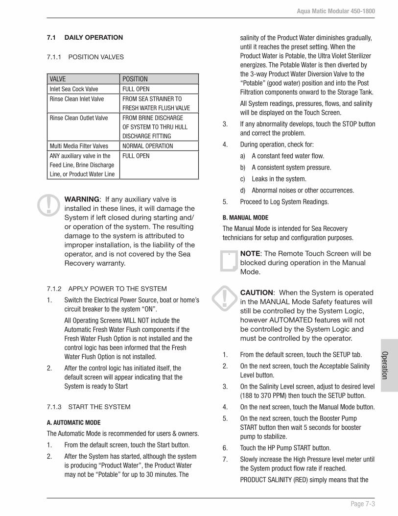
Aqua Matic Modular 450-1800
Page 7-3
Operation
salinity of the Product Water diminishes gradually, until it reaches the preset setting. When the Product Water is Potable, the Ultra Violet Sterilizer energizes. The Potable Water is then diverted by the 3-way Product Water Diversion Valve to the “Potable” (good water) position and into the Post Filtration components onward to the Storage Tank.
All System readings, pressures, flows, and salinity will be displayed on the Touch Screen.
3. If any abnormality develops, touch the STOP button and correct the problem.
4. During operation, check for:
a) A constant feed water flow.
b) A consistent system pressure.
c) Leaks in the system.
d) Abnormal noises or other occurrences.
5. Proceed to Log System Readings.
B. MANUAL MODE
The Manual Mode is intended for Sea Recovery technicians for setup and configuration purposes.
NOTE: The Remote Touch Screen will be blocked during operation in the Manual Mode.
CAUTION: When the System is operated in the MANUAL Mode Safety features will still be controlled by the System Logic, however AUTOMATED features will not be controlled by the System Logic and must be controlled by the operator.
1. From the default screen, touch the SETUP tab.
2. On the next screen, touch the Acceptable Salinity Level button.
3. On the Salinity Level screen, adjust to desired level (188 to 370 PPM) then touch the SETUP button.
4. On the next screen, touch the Manual Mode button.
5. On the next screen, touch the Booster Pump START button then wait 5 seconds for booster pump to stabilize.
6. Touch the HP Pump START button.
7. Slowly increase the High Pressure level meter until the System product flow rate if reached.
PRODUCT SALINITY (RED) simply means that the
7.1 DAILY OPERATION
7.1.1 POSITION VALVES
VALVE POSITIONInlet Sea Cock Valve FULL OPEN
Rinse Clean Inlet Valve FROM SEA STRAINER TO FRESH WATER FLUSH VALVE
Rinse Clean Outlet Valve FROM BRINE DISCHARGE OF SYSTEM TO THRU HULL DISCHARGE FITTING
Multi Media Filter Valves NORMAL OPERATION
ANY auxiliary valve in the Feed Line, Brine Discharge Line, or Product Water Line
FULL OPEN
WARNING: If any auxiliary valve is installed in these lines, it will damage the System if left closed during starting and/or operation of the system. The resulting damage to the system is attributed to improper installation, is the liability of the operator, and is not covered by the Sea Recovery warranty.
7.1.2 APPLY POWER TO THE SYSTEM
1. Switch the Electrical Power Source, boat or home’s circuit breaker to the system “ON”.
All Operating Screens WILL NOT include the Automatic Fresh Water Flush components if the Fresh Water Flush Option is not installed and the control logic has been informed that the Fresh Water Flush Option is not installed.
2. After the control logic has initiated itself, the default screen will appear indicating that the System is ready to Start
7.1.3 START THE SYSTEM
A. AUTOMATIC MODE
The Automatic Mode is recommended for users & owners.
1. From the default screen, touch the Start button.
2. After the System has started, although the system is producing “Product Water”, the Product Water may not be “Potable” for up to 30 minutes. The

Aqua Matic Modular 450-1800
Page 7-4
Oper
atio
n
B. MANUAL MODE
This mode of operation is intended for Sea Recovery technicians for setup and configuration purposes.
1. From the Manual Mode screen, reduce the Pressure to 0 psi (0 bar) using the - (negative) button.
2. Touch the Diversion Valve button to de-activate.
3. Touch the HP Pump STOP button.
4. Touch the Booster Pump STOP button.
The Automated Fresh Water Flush will NOT activate automatically because operation during the Manual Mode deactivates all Automated features. In order to perform a Fresh Water Flush follow the directions in Section 7.3:
BOAT SAFETY WARNING: The Inlet Thru-Hull Sea Cock Valve is in the Open position. It is recommended for the safety of the boat to close the Sea Cock Valve when ever the System is not in use. This will protect the boat from water flooding should a hose or component fail.
AUTOMATIC OPERATION WARNING: If the Automatic Fresh Water Flush option is installed and if the System Control Logic has been set to perform Automatic Fresh Water Flushing, the Touch Pad will show the operator when this automatic cycle will be performed.
7.2 SYSTEM STORAGE AND CLEANING
R.O. MEMBRANE ELEMENT HANDLING AND SYSTEM STORAGE CAUTIONS:
TEMPERATURE: Never store the R.O. membrane element or Membrane/Vessel Assembly in direct sunlight. Never expose the R.O. membrane element or Membrane/Vessel Assembly to storage temperatures above 120° F (50° C) or below 32° F (0° C). High temperatures cause up to 40% loss of production from the R.O. membrane element. This damage is irreversible. Freezing temperatures cause mechanical damage to the system and irreversible damage to the R.O. membrane element.
DRYING OUT: Never allow the R.O. membrane element to dry out, as 40% production loss occurs. This membrane damage may be irreversible. Some, but not all, production may be restored by saturating the R.O.
dissolved solids in the Product Water have not yet decreased to acceptable level.
Although the system is producing “Product Water”, the Product Water may not be “Potable” for up to 30 minutes. The salinity of the Product Water diminishes gradually, until it reaches the acceptable level or lower.
PRODUCT SALINITY (GREEN) simply means that the dissolved solids in the Product Water have reached the acceptable level and the Diversion Valve can be activated.
8. Activate the Diversion Valve.
Touch the Diversion Valve button. This will cause the UV Sterilizer to energize, and the 3-Way Product Water Diversion Valve to energize and divert “Potable” (good water) into the Post Filtration and onward to the Ship’s Storage Tank.
All System readings, pressures, flows, and salinity will be displayed on the Main Touch Screen.
If any abnormality develops, touch the STOP button on the top right corner of the screen.
A warning screen will display.
Correct the problem then repeat Step 1-8.
9. Check for:
a) A constant feed water flow.
b) A consistent system pressure.
c) Leaks in the system.
d) Abnormal noises or other occurrences.
7.1.5. LOG SYSTEM READINGS
1. Record the System performance readings. Use the Daily System Readings form on Page 7-11.
2. Proceed to Shutdown.
7.1.6. SHUTDOWN THE SYSTEM
A. AUTOMATIC MODE
1. From the default screen, touch the STOP button.
If the Automatic Fresh Water Flush option is not installed the shut down sequence is complete:
If the Automatic Fresh Water Flush option is installed the Automatic Fresh Water Flush cycle will start:

Aqua Matic Modular 450-1800
Page 7-5
Operation
Winterize the System, and also to Discharge the contents of the cleaning solution bucket.
When the instructions within this section state “configure for Once Through Rinse” refer to page 7-6, figure 7a and proceed as follows:
1. Configure the Suction line for a Once Through Configuration (fig. 7a). Disconnect the outlet line from the Sea Strainer and place it in the Rinse/Clean Bucket or Container. Or if the system is equipped with the optional Rinse Clean Inlet Valve then position this valve to draw from the Rinse/Clean Bucket or Container.
- also -
2. Configure the Brine Discharge line for a Once Through Configuration (fig. 7a). Connect the Brine Discharge Line from the system to the Thru-Hull over board discharge fitting, normal connection for normal operation. Or if the system is equipped with the optional Rinse Clean Outlet Valve then position this valve to discharge through the Thru-Hull fitting, normal connection for normal operation.
When the instructions within this section state “configure for Closed Loop” refer to page 7-6, figure 7b and proceed as follows:
1. Configure the Suction line for a Closed Loop Configuration (fig. 7b). Disconnect the outlet line from the Sea Strainer and place it in the Rinse/Clean Bucket or Container. Or if the system is equipped with the optional Rinse Clean Inlet Valve then position this valve to draw from the Rinse/Clean Bucket or Container.
- also -
2. Configure the Brine Discharge line for a Closed Loop Configuration (fig. 7b). Disconnect the Brine Discharge Line from the Thru-Hull over board discharge fitting and place it in the Rinse/Clean Bucket or Container. Or if the system is equipped with the optional Rinse Clean Outlet Valve then position this valve to return to the Rinse/Clean Bucket or Container.
membrane element in product water for several days and then operating the system using product water feed into the system for a continuous 48 hour period. The R.O. membrane element must remain wet at all times.
BIOLOGICAL FOULING: Protect the R.O. membrane element from biological fouling. Production loss occurs if the element becomes fouled by biological slimes. Some, but not all, production may be restored after cleaning.
CHEMICAL FOULING: Never expose the R.O. membrane Element to chemicals other than those supplied by SRC. Use caution when operating the system in harbors that may be polluted with chemicals, oil, or fuel. Chemicals may damage the R.O. membrane element beyond repair.
WARNING: NEVER USE THIRD PARTY CHEMICALS, ONLY USE SEA RECOVERY SUPPLIED CHEMICALS. Third party chemicals are not compatible with various materials used in the Sea Recovery System. Copolymer parts within the Sea Recovery System will be dissolved by third party chemicals. Third party chemicals will destroy the Sea Recovery R.O. membrane element. Damage to the Sea Recovery System or components within the System are not covered by the Sea Recovery Warranty.
STORAGE: The dark and moist interior of a membrane element is an excellent breeding ground for microorganisms. Simply operating the system does not protect the R.O. membrane element from production loss due to biological fouling. During short-term shutdowns, the system must be rinsed as explained in the following pages. During long-term shutdowns, the system must be rinsed as well as chemically treated.
NEW SYSTEM STORAGE: If the R.O. membrane elements are installed in the System and if the System will not be installed and commissioned within a 3 months from receipt refer to the procedures for either Short Term or Long Term storage.
Illustrations on Page 7-6 - figure 7a, show the flow of water in a Once-Through-Rinse operation and in a Closed Loop operation. These illustrations may be referred to during the Rinse, Clean, and Storage procedures.
The illustration on Page 7-7 - figure 7c, demonstrates a simplified Once Through Configuration
This is used to Rinse the System with Fresh Water, to

Aqua Matic Modular 450-1800
Page 7-6
Oper
atio
n
Note: The above illustrations show representations of components and may not show actual or all components.
Figure 7a: ONCE THROUGH RINSE
Figure 7b: RECIRCULATING CLOSE LOOP
This is used to rinse the system with fresh water, to winterize the system, and also to discharge the content if the cleaning solution bucket.
This is used to circulate cleaning or storage solution through the system.

Aqua Matic Modular 450-1800
Page 7-7
Operation
Figure 7c: Simplified Aqua Matic Once Through Rinse
Figure 7d: Simplified Aqua Matic Re-Circulating Loop

Aqua Matic Modular 450-1800
Page 7-8
Oper
atio
n
7.4 LONG TERM SHUTDOWN
A Long Term or Prolonged Shutdown is a period in which the system goes unused for longer than three months, depending on conditions.
For this interval, the system should first be rinsed with fresh water then stored with system and Membrane Element Storage Chemical (SRC SC). This chemical inhibits bacterial growth while maintaining the high flux and salt rejection of the R.O. membrane element.
ITEMS REQUIRED
a) 20 gallons (75.7 liters) of potable water.
b) Sea Recovery Storage Chemical SRC SC
c) 2 Gallons (7.5 liters) of food grade glycerin (propylene glycol) if the System will be Winterized
NOTE: If the system is equipped with an automatic Fresh Water Flush Accessory then it is not necessary to read this section as long as the Automatic Fresh Water Flush cycle remains active. The Automatic Fresh Water Flush option rinses the system every preset number of days automatically. However, see “Winterizing and Freezing” note below.
NOTE: WINTERIZING AND FREEZING TEMPERATURE STORAGE If the system is exposed to freezing temperatures, DO NOT activate the Automatic Fresh Water Flush. Instead, perform a Manual Fresh Water Rinse as described below.
Follow the directions below if the system will not be used for several months or if the system is not equipped with an Automatic Fresh Water Flush option, or if the System is to be Winterized against freezing temperatures. This procedure displaces the system feed water with Storage Chemical or Storage Chemical and propylene glycol.
LONG TERM SHUTDOWN PROCEDURE
1. Close the Inlet Sea Cock Valve.
2. Fill a 10-gallon (37.8 liters) container with clean, potable water.
3. Configure the system for a Once Through Rinse (Page 7-6, figure 7a).
7.3 SHORT-TERM SHUTDOWN
A short-term shutdown is defined as a period of time in which the system is not utilized for up to four weeks. An effective short-term protection for the system and R.O. membrane element is a Fresh Water Rinse of the entire system with fresh water (product water from the system). This prolongs the system life by minimizing electrolysis and retarding biological growth.
WARNING: WINTERIZING AND FREEZING TEMPERATURE STORAGE NOTE: If the system is exposed to freezing temperatures, DO NOT activate the Automatic Fresh Water Flush. Instead, perform a Manual Fresh Water Rinse below.
MANUAL FRESH WATER RINSE PROCEDURE
Follow the directions below if the system is not equipped with an Automatic Fresh Water Flush option, or if the System is to be Winterized against freezing temperatures. This procedure displaces the system feed water with fresh water and allows a short-term shutdown for up to four weeks, and adds propylene glycol if Winterizing. Ten gallons (38 liters) of fresh product or potable water is required for the fresh water rinse, and 2 gallons (7.5 liters) food grade glycerin (propylene glycol) is required for Winterizing.
1. Close the Inlet Sea Cock Valve.
2. Fill a 10-gallon container with clean, fresh water.
WARNING: IF THE SYSTEM WILL BE EXPOSED TO FREEZING TEMPERATURES add 20% (2 gallons or 7.5 liters) food grade glycerin (propylene glycol) to 10 gallons (37.8 liters) of potable water in the Bucket. This prevents the water in the system from freezing.
3. Configure the system for a Once Through Rinse (Page 7-6, fig 7a).
4. Start the System in the MANUAL MODE
Operation of the System will deplete the Fresh Water or Water and Propylene Glycol mixture in the bucket. Just prior to depleting the Water or mixture in the Bucket Stop the System.
5. Proceed to Section 7.5.

Aqua Matic Modular 450-1800
Page 7-9
Operation
7.6 R.O. MEMBRANE CLEANING
Do not arbitrarily clean the R.O. membrane in a NEW system. The R.O. membrane element in a NEW System will not be fouled with any substance that is cleanable. Low production or high salinity of the Product water from a NEW System will be attributed to factors other than fouling.
If a NEW system experiences low production this would indicate that there is a blockage in the Product Water Line, the feed water temperature is low, the operating pressure is low, or the R.O. membrane element has dried out prior to use. A NEW System experiencing low production should be operated for up to 48 hours continuously to clear and saturate the R.O. membrane element and product water channel. Correlate and compensate operating pressure, feed water temperature, and feed water salinity as charted in the Section 2.
If a NEW System still experiences low production after 48 hours of continual operation, then contact the factory. If a NEW System experiences poor quality Product Water, high in salinity, this would be attributed to a mechanical failure such as a broken or missing O-ring and will be accompanied with high production at low operating pressure. For problems with a NEW System refer to the Troubleshooting section.
The membrane element requires cleaning from time to time. Biological growth and salt accumulation eventually make replacement necessary. The frequency of required cleaning depends on the amount of production loss and salt rejection loss resulting from normal use. In order to properly assess performance changes, it is important to maintain daily log readings for comparison.
During performance comparisons, Feed Water Temp, Feed Water Salinity, and System Operating Pressure must be taken into consideration and compensated for. After compensations, a 10% decline in productivity (GPH Flow) and/or a 10% increase in salt passage indicate that the R.O. membrane element may require cleaning.
If production rate has dropped dramatically since the last time the system was used, this may be due to drying out of the R.O. membrane element and/or fouling during storage. If the system has not been used for several months and the production rate has dropped dramatically since the last time used, try operating the system for 48 or more continuous hours to saturate the Product Water Channel within the R.O. membrane element.
4. Start the System in the MANUAL MODE
Operation of the System will deplete the Fresh Water in the bucket. Just prior to depleting the Water in the Bucket Touch STOP.
5. Once again, fill a 10-gallon (37.8 liters) container with 10 gallons (37.8 liters) clean, potable water.
6. Add to the Fresh Water in the bucket or Fresh Water and Propylene glycol, 4 ounces of Sea Recovery Storage Chemical SRC SC.
7. Configure the system for a Recirculating Closed Loop configuration as illustrated on Page 7-6.
8. Start the System in the MANUAL MODE
Operate the System in the Recirculating Closed Loop configuration for 10 minutes. After 10 minutes stop the system:
9. Proceed to Section 7.5.
7.5 WINTERIZING PROCEDURE
If the System will be exposed to freezing temperatures the Post Filtration Section of the System must be drained of all Product Water.
a) Charcoal Filter
1) Remove the Charcoal Filter bowl.
2) Remove the water from the bowl.
3) Replace the Charcoal Filter Element with a New Charcoal Filter Element.
4) Replace the bowl back onto the lid.
b) pH Neutralizing Filter
1) Remove the pH Neutralizing bowl.
2) Remove the water from the bowl.
3) Replace the bowl and pH element back onto the lid.
c) UV Sterilizer
1) Disconnect the product water line from the UV Sterilizer filter and drain the product water from it.
1. Switch the Power to the System OFF.
2. Lock and Tag the Power Breaker to ensure that no one will accidentally operate the System and displace the Winterizing Mixture with Feed or Fresh Water.
3. Discard the Storage Chemical in an environmentally safe manner.

Aqua Matic Modular 450-1800
Page 7-10
Oper
atio
n
5. SRC MCC-2, Membrane Cleaning Compound “# 2” is an acid cleaner designed to clean calcium carbonate and other mineral deposits from the R.O. membrane element. Mineral fouling is a slow process which takes place during use of the system. Therefore, if the system has relatively few hours of use yet shows signs of R.O. membrane element fouling then that fouling is likely biological fouling. If the system has several thousand hours of use then there may be some mineral fouling combined with biological fouling.
6. SRC MCC-3, Membrane Cleaning Compound “# 3” is used for iron fouling. It is not included in the SRC Membrane Cleaning Chemical kit. If the system’s R.O. membrane element is fouled with rust from iron piping, then SRC CC-3 may be used for effective removal of light or moderate rust fouling. Heavily rust fouled RO membranes may not be recoverable as rust not only fouls the Membrane Element but also damages the membrane surface.
WARNING: DO NOT mix different chemicals together. DO NOT use different cleaning chemicals together at the same time. Mix the cleaning chemicals separately and use them separately. Use only Sea Recovery supplied chemicals. NEVER use third party non-Sea Recovery chemicals.
CLEANING PROCEDURE
Product Water Required, in U.S. Gallons for Cleaning of the R.O. membrane element:
Chemical Rinse water required
Cleaning water required
Second rinse water required
Total water required
CC-1 10 10 10 30
CC-2 10 10 20
CC-3 10 10 20
1. Close the Inlet Sea Cock Valve.
2. If installed, position the Multi Media Filter Valves in the Multi Media Filter By-Pass position to by-pass it during the cleaning procedures See illustration on the right for Multi Media Filter Valve positioning.
If production rate drops dramatically from one day to another, this may be due to chemical attack which is not cleanable. Sewage chemicals or petroleum products cause irreparable damage to the R.O. membrane element. Suspended solids fouling resulting from silt, coral dust, iron (rust), river or inland waterway debris, or other small solid matter may not be cleanable.
R.O. WATER AND CHEMICAL REQUIREMENTS
1. The system must be rinsed with fresh water before any cleaning procedure, cleaned, and then rinsed again.
2. The process of rinsing and cleaning the R.O. membrane elements with just one cleaning compound requires 30 gallons (113.5 liters) of fresh non-chlorinated product water. If a second cleaning is performed using a different cleaning compound an additional 20 gallons (75.7 liters) will be required per additional cleaning.
3. The Sea Recovery Reverse Osmosis cleaning compounds are designed to clean in a closed loop configuration moderate fouling from the R.O. membrane element. If the R.O. membrane element is excessively fouled and in-field cleaning is not successful, the R.O. membrane element may be returned to Sea Recovery or to one of Sea Recovery’s many Service Dealers for professional chemical cleaning. If your membrane requires professional cleaning, please contact Sea Recovery for a Return Authorization Number, price quotation, and return instructions. Due to the complexity of and time involvement in professionally cleaning the R.O. membrane element it can be more cost effective to replace a heavily fouled R.O. membrane element. Always compare the cost of cleaning vs the cost of replacement in order to make the proper decision to clean or replace.
4. SRC MCC-1, Membrane Cleaning Compound “# 1” is an alkaline cleaner designed to clean biological fouling and slight oil fouling from the R.O. membrane element. Biological fouling is usually the first cause of the R.O. membrane element fouling. The system is constantly exposed to seawater and biological growth occurs from the first day forward. If exposed to seawater and left to sit, the R.O. membrane element becomes fouled even with no actual system use. This fouling is minimized with fresh water rinsing whenever the system is not in use.

Aqua Matic Modular 450-1800
Page 7-11
Operation
Figure 7c : Multi Media Filter - Valve position on By Pass. Position your Multi media Filter on ByPass as shown above during cleaning procedure.
3. Replace the Pre-filtration Cartridge with a new SRC supplied Pre-filtration Element.
4. Fill a 10-gallon (37.8 liters) container with clean, fresh water.
5. Configure the system for a Once Through Rinse as illustrated on Page 7-6.
6. Start the System in the MANUAL MODE
Operation of the System will deplete the Fresh Water in the bucket. Just prior to depleting the Water in the Bucket Touch STOP.
7. Once again, fill the container with 10 gallons (37.8 liters) clean, fresh water.
8. Add to the 10 gallons (37.8 liters) of fresh water 1.5 lbs. (0.68 kg) of Sea Recovery Membrane Cleaning Compound MCC 1, MCC 2 or MCC 3. Thoroughly mix the solution until the cleaning compound has dissolved.
9. Configure the system for a Recirculating Closed Loop configuration as illustrated on Page 7-6.
10. Start the System in the MANUAL MODE
11. Operate the System in the Recirculating Closed Loop configuration for 60 minutes. After 60 minutes stop the system as follows:
12. Configure the system for a Once Through Rinse configuration as illustrated on Page 7-6.
13. Start the System in the MANUAL MODE to discharge the cleaning chemical to waste.
Operation of the System will deplete the cleaning solution in the bucket. Just prior to depleting the solution in the Bucket stop the System.
14. One final time, fill the container with 10 gallons (37.8 liters) clean, fresh water.
15. Configure the system for a Recirculating Closed Loop configuration as illustrated on Page 7-6.
16. Start the System in the MANUAL MODE
Operate the System in the Recirculating Closed Loop configuration for 10 minutes. After 10 minutes stop the system as follows:
17. Configure the system for a Once Through Rinse configuration as illustrated on Page 7-6.
18. Start the System in the MANUAL MODE to discharge the rinse water to waste.
Operation of the System will deplete the cleaning solution in the bucket. Just prior to depleting the solution in the Bucket Stop the System as follows:
The system is now ready for additional cleaning, use, or storing.
If further membrane cleaning is necessary, repeat Steps 4 to 18 above for each additional cleaning.
19. If System will be expose to freezing temperature, proceed to Section 7.5:

Aqua Matic Modular 450-1800
Page 7-12
Oper
atio
n
Sea Recovery Aqua Matic
DAILY SYSTEM READINGS
Make Copies of this form and fill one in each time the System is operated. Record the following information after one hour of continuous proper operation of the system, or just prior to stopping the System.Retain these forms in this Owner’s Manual for future reference. This information is valuable to the servicing technicians in providing technical support of the Aqua Matic. Provide this information to service technicians when requesting technical assistance.
Date Installed: ___________________________ Date Commissioned: _______________________
Model Information:System Serial Number: ___________________________Style: ___ Compact _____ ModularR.O. Membrane/Vessel Assy Quantity: ___ 1 (one) ___ 2 (two)System Capacity: ___ 450 GPD ___ 700 GPD ___ 900 GPD ___ 1400 GPD ___ 1800 GPDSystem Power: ________ Volts AC ________ Hz __________ PhaseFeed Water Temperature: ________ degrees Fahrenheit or ________ degrees CelsiusHour Meter Reading: __________ Hours
PRESSURE READINGS:Low Pressure Transducer #1 ________ psi or ________ kPaPressure Differential Pressure ________ psi or ________ kPaLow Pressure Transducer #2 ________ psi or ________ kPaHigh Pressure Transducer ________ psi or ________ kPa
WATER FLOW METER READINGS:Flow Meter Product Water: ________ US Gallons Per Hour or ________ Liters Per HourFlow Meter Brine Discharge: ________ US Gallons Per Minute or ________ Liters Per Minute
WATER QUALITY:Feed Water Salinity: __________ ppm or Location of use: ____________________________________Product Water Salinity: ______________ ppmProblems, Unusual Occurrences, or Unusual Noises: _____________________________________________
_______________________________________________________________________________________________
_______________________________________________________________________________________________
_______________________________________________________________________________________________
_______________________________________________________________________________________________
_______________________________________________________________________________________________
_______________________________________________________________________________________________
_______________________________________________________________________________________________
_______________________________________________________________________________________________
_______________________________________________________________________________________________
Maintenance
Aqua Matic Modular 450-1800
Section 8 - MAINTENANCE AND REPAIR

Mai
nten
ance
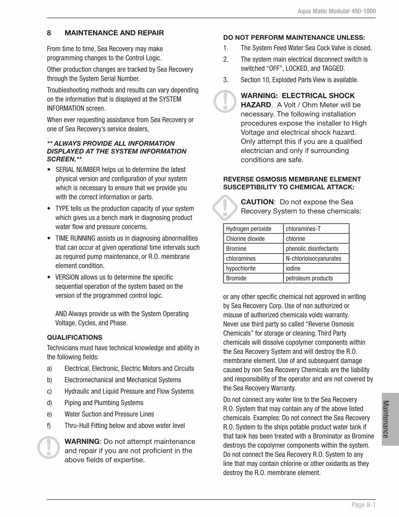
Aqua Matic Modular 450-1800
Page 8-1
Maintenance
DO NOT PERFORM MAINTENANCE UNLESS:
1. The System Feed Water Sea Cock Valve is closed.
2. The system main electrical disconnect switch is switched “OFF”, LOCKED, and TAGGED.
3. Section 10, Exploded Parts View is available.
WARNING: ELECTRICAL SHOCK HAZARD. A Volt / Ohm Meter will be necessary. The following installation procedures expose the installer to High Voltage and electrical shock hazard. Only attempt this if you are a qualified electrician and only if surrounding conditions are safe.
REVERSE OSMOSIS MEMBRANE ELEMENT SUSCEPTIBILITY TO CHEMICAL ATTACK:
CAUTION: Do not expose the Sea Recovery System to these chemicals:
Hydrogen peroxide chloramines-T
Chlorine dioxide chlorine
Bromine phenolic disinfectants
chloramines N-chlorioisocyanurates
hypochlorite iodine
Bromide petroleum products
or any other specific chemical not approved in writing by Sea Recovery Corp. Use of non authorized or misuse of authorized chemicals voids warranty. Never use third party so called “Reverse Osmosis Chemicals” for storage or cleaning. Third Party chemicals will dissolve copolymer components within the Sea Recovery System and will destroy the R.O. membrane element. Use of and subsequent damage caused by non Sea Recovery Chemicals are the liability and responsibility of the operator and are not covered by the Sea Recovery Warranty.
Do not connect any water line to the Sea Recovery R.O. System that may contain any of the above listed chemicals. Examples: Do not connect the Sea Recovery R.O. System to the ships potable product water tank if that tank has been treated with a Brominator as Bromine destroys the copolymer components within the system. Do not connect the Sea Recovery R.O. System to any line that may contain chlorine or other oxidants as they destroy the R.O. membrane element.
8 MAINTENANCE AND REPAIR
From time to time, Sea Recovery may make programming changes to the Control Logic.
Other production changes are tracked by Sea Recovery through the System Serial Number.
Troubleshooting methods and results can vary depending on the information that is displayed at the SYSTEM INFORMATION screen.
When ever requesting assistance from Sea Recovery or one of Sea Recovery’s service dealers,
** ALWAYS PROVIDE ALL INFORMATION DISPLAYED AT THE SYSTEM INFORMATION SCREEN.**
• SERIAL NUMBER helps us to determine the latest physical version and configuration of your system which is necessary to ensure that we provide you with the correct information or parts.
• TYPE tells us the production capacity of your system which gives us a bench mark in diagnosing product water flow and pressure concerns.
• TIME RUNNING assists us in diagnosing abnormalities that can occur at given operational time intervals such as required pump maintenance, or R.O. membrane element condition.
• VERSION allows us to determine the specific sequential operation of the system based on the version of the programmed control logic. AND Always provide us with the System Operating Voltage, Cycles, and Phase.
QUALIFICATIONS
Technicians must have technical knowledge and ability in the following fields:
a) Electrical, Electronic, Electric Motors and Circuits
b) Electromechanical and Mechanical Systems
c) Hydraulic and Liquid Pressure and Flow Systems
d) Piping and Plumbing Systems
e) Water Suction and Pressure Lines
f) Thru-Hull Fitting below and above water level
WARNING: Do not attempt maintenance and repair if you are not proficient in the above fields of expertise.
Aqua Matic Modular 450-1800
Page 8-2
Mai
nten
ance
modified by Sea Recovery for a specific purpose of compatibility and are not commercially available from other sources.
Many of these special components can appear to be similar to Sea Recovery components. Extensive and expensive damage to the Sea Recovery System WILL result if incompatible components are used in the Sea Recovery System. Damage caused to the Sea Recovery System as a result of third party components is the liability and responsibility of both the Marine Dealer that sold the component for use in the Sea Recovery System as well as the Owner/Operator that purchased and installed the third party component in the Sea Recovery System and is not covered by the Sea Recovery Warranty.
Always insist on only Sea Recovery supplied components, spares, and consumable.
8.3 INDIVIDUAL COMPONENT MAINTENANCE AND REPAIR
The components are listed in order of their ID number assigned in the P&ID in Section 3.
1. Inlet Thru Hull Fitting: Non Sea Recovery component. Keep the Inlet Thru Hull Fitting free and clear of debris and marine growth. If the Inlet Thru Hull Fitting is clogged, this results in a low feed pressure condition, which causes the system to shut off.
Blockage at the Inlet Thru-Hull Fitting causes the System to shut off due to lack of Feed Water Flow. Unfortunately, since it is under water operators are reluctant to thoroughly inspect the Inlet Thru-Hull Fitting for problems. This can cause time consuming frustrations in attempting to gain feed water flow by trouble shooting other components in the System.
The Inlet Thru-Hull Fitting must be free and clear allowing the System to draw 4.5 U.S. Gallons (17 Liters) Per Minute through it with minimal resistance. Any blockage at the Inlet Thru-Hull Fitting will cause low pressure and low flow problems at the System. This Inlet Thru-Hull Fitting must be a Forward Facing Scoop so that the System receives a positive flow of water as the boat is under way. It must be minimum 3/4 in. (19 mm) inside diameter. It must be installed in a position on the bottom of the Hull so as to allow free flowing Feed Water without air.
If you use detergents to clean the internal wetted parts of the system ensure that they are rinsed thoroughly, wiped and dried prior to reassembly. After the components have been reassembled, product water can be used to remove any feed water residue from the exterior surfaces of the components.
USE OF NON-AUTHORIZED OR MISUSE OF AUTHORIZED CHEMICALS VOIDS SYSTEM WARRANTY.
8.1 WEEKLY QUICK CHECK
The following steps ensure that potential problems are resolved preventing major repairs:
1. Inspect all fasteners for tightness including brackets, screws, nuts, and bolts. Pay special attention to the High Pressure Pump and Electric Motor since they are subject to increased vibration.
2. Clean any salt water or salt deposits from the system with a wet rag.
3. Check for water leaks throughout the System and supporting water lines.
4. Check all tubing and high-pressure hoses for wear and abrasion against rough surfaces. The hoses must not contact heated or abrasive surfaces.
8.2 OPERATOR MAINTENANCE INTERVALS
The frequency of required maintenance is dependent on the regularity of usage, the condition of the intake water (the location of use), the length of time the system is exposed to water, the total running time and, in some cases, the manner in which the system is installed or operated. Because of these factors, it is virtually impossible to comprise an exact timetable for required maintenance. The maintenance timetable, Page 8-3, is an estimate of the time intervals at which maintenance may be required on the various system components. This is based upon factual data compiled from Sea Recovery installations around the world. However, this schedule must be adjusted to each individual system depending upon the variables listed.
WARNING: Components, spares, and consumable utilized within the Sea Recovery System can be specific to Sea Recovery specifications and are not commercially available from other sources. Other Components utilized within the Sea Recovery System are

Aqua Matic Modular 450-1800
Page 8-3
Maintenance
COMPONENT MAINTENANCE REQUIRED TIME INTERVAL CONTINUOUS TIME INTERVAL INTERMITTENT DUTY
Sea Strainer Inspect & Clean Screen & Housing
weekly 100 hours
Plankton Filter Inspect & clean weekly 100 hours
Multi Media Filter Back wash & Rinse when pressure drops 20 PSI (1.37 BAR) across the filter
Pre-filter Replace element(s) Low Pressure <10 psi (0.68 BAR) Low Pressure <10 psi (0.68 BAR)
Oil/water Separator Replace element Low Pressure <10 psi (0.68 BAR) Low Pressure <10 psi (0.68 BAR)
Std HP Pump
Opt HP Pump
Internal Service
Change OilReplace Seal KitReplace Valve Kit
Approxi 8000 hrs
500 hrs2000 hrs2000 hrs
500 hrs2000 hrs2000 hrs
R. O. Membrane Clean Element When production or salt rejection decreases by 10%
Salinity Probe Clean Probes Annually Annually
Charcoal Filter Replace Element 3 months 3 months
pH Neutralizing Cartridge Replace Cartridge clean quartz sleeve
when calcium carbonate granules are depleted
UV Sterilizer Replace lamp & 2000 Hours 2000 Hours
Fresh Water Flush Charcoal Element
Replace Element 3 months 3 months
CAUTION: A flat profile, flush mount, inlet thru-hull fitting will cause a vacuum as the boat is under way, and this will cause loss of feed water flow and cavitation of the Booster Pump and High Pressure Pump resulting in continual system shut down due to low feed water flow and pressure. The resulting failure of the system to remain in operation is attributed to improper installation, is the liability of the installer, and is not covered by the Sea Recovery warranty.
CAUTION: If the thru-hull fitting has been placed in a position on the underside of the hull that allows air to continually enter the thru-hull fitting, this will cause the system to continually shut down due to loss of feed water. The resulting failure of the system to remain in operation is attributed to improper installation, is the liability of the installer, and is not covered by the Sea Recovery warranty.
CAUTION: The Sea Recovery System must not be tied into another existing auxiliary water line already supplying another accessory on the boat. Using one Thru Hull fitting for other equipment will cause the Sea Recovery System to draw air or cavitate leading to continual system shut down. The resulting failure of the system to remain in operation is attributed to improper installation, is the liability of the installer, and is not covered by the Sea Recovery warranty.
CAUTION: If the Sea Recovery System is connected to a Sea Chest or Stand Up Pipe, do not plumb the Sea Recovery System feed line to the “top” of the Sea Chest or Stand Up Pipe. If plumbed into the top of these feed water arrangements, the Sea Recovery System will experience continual shut down due to air inducement into the system. The resulting failure of the system to remain in operation is attributed to improper
Maintenance Timetable:

Aqua Matic Modular 450-1800
Page 8-4
Mai
nten
ance
due to external source, not the motor itself, then correct the cause or else the replacement or repaired motor will fail again.
Failures of the electric motor may be:
Winding failure. Generally caused by low or high power, below or above the specified voltage requirements of the system. This is Not economically repairable.
Capacitor failure. Generally caused by low power feeding the motor and or low cycles from the power source. Also caused by rapidly repeating starting and stopping of the motor. Field replaceable.
The Electric Motor is 1/2 horse power, Totally Enclosed Fan Cooled, 2 pole, dual Cycle, and dual Voltage.
WARNING: The Booster Pump MUST rotate in the COUNTER CLOCKWISE DIRECTION ONLY Rotating the Booster Pump in the clockwise direction will cause extensive damage to it. Never operate the Booster Pump in the clockwise direction.
WARNING: When switching from Three Phase Generator power to Three Phase Shore power ALWAYS check phases prior to operating the System else Reverse Rotation along with extensive damage to the Booster Pump will occur should the power be out of phase.
Problems and Symptoms appearing and caused by the Booster Pump or its Electric Motor:
1. The Single Phase (115 or 230 VAC) Electric Motor “hums”, pulls starting current (locked rotor) amperage, does not rotate, and trips the supply power circuit breaker when attempting to operate the System.
The Single Phase Electric Motor is a capacitor start motor. If the motor was started with low voltage, a drop in voltage during starting, and if this was repeated several times in rapid concession
installation, is the liability of the installer, and is not covered by the Sea Recovery warranty. Plumb the Sea Recovery System to the “bottom” of such feed water arrangements to ensure a continual air free supply of feed water to the system.
2. Sea Cock Valve: Non Sea Recovery component. The packing and connections of the Inlet Sea Cock Valve must be tight and must properly seal. Clean the valve cavity of debris or replace the seal and seat or the entire valve, as required. This section is under a vacuum condition while operating the system. Loose fittings or a worn seal will allow air to enter the Sea Recovery system causing continual shut down due to subsequent low feed water pressure.
3. Inlet Connection: Replace if damaged.
4. Inline Vacuum / Pressure Gauges: If the Vacuum/Pressure gauge needle does not move; or does not register proper vacuum or pressure this may be caused by a plugged orifice. The Vacuum/Pressure Gauges have a very small orifice at the bottom of the pipe fitting end. This orifice can become plugged with debris or corrosion. Using a small diameter wire clean the debris from the orifice. Replace the gauge if cleaning of the orifice does not restore functionality.
5. Sea Strainer: Keep the mesh screen free and clear of debris. When the mesh screen is clogged, it results in a low-pressure condition causing system shut off. This section is under a vacuum condition while operating the system. If the Sea Strainer’s bowl is loose or if the O-ring seal is worn or not properly seated, air will enter the system causing continual shut down due to subsequent low feed water pressure.
6. Booster Pump: (centrifugal; counter clockwise rotation as viewed from volute end {front end} of pump)
A. Electric Motor:
Troubleshoot electric motor failure to ensure that any abnormality from the power, wiring, connections, contactors, or control circuit are not at fault or at cause. If the electric motor has failed, it will require repair. However, depending upon failure, replacement may be more cost effective than repair. If failure of the motor is

Aqua Matic Modular 450-1800
Page 8-5
Maintenance
b) Measure voltage at the motor during attempt to start it. If voltage drops more than 10% locate and correct the reason. Cross check voltage across all 3 power leads.
c) Check the motor starter relay (contactor) for “burnt” contacts.
3. The Electric Motor makes an unusual “grinding” sound when operated.
Solutions:
a) Check and replace as necessary the front and rear bearings.
b) Check to see if the fan is rubbing against the fan guard.
B. Booster Pump:
Replace the ceramic seal approximately every 2000 hours, or at the sign of leakage:
DISASSEMBLY:
Remove the four 3/8-16 Bolts holding the volute to the motor bracket. To remove the impeller, remove the bearing cap on the motor to expose the screwdriver slot on the motor shaft. Hold the motor shaft with a large screwdriver and remove the impeller by grasping it with your hand and turning the impeller counter clockwise. Remove the Seal. Two screwdrivers wedged into the seal at 180º apart serve as tools to wedge the seal out. The ceramic seat is removed by removing the end bell gasket.
REASSEMBLY:
Clean the motor shaft and the bracket of any corrosion or salt deposits. Replace the end bell gasket and the tap seat portion into the bracket cavity. Use a new gasket. Place the ceramic seat into the cavity over the shaft. Make sure that the polished side is toward the end of the shaft. Tap into place evenly using a hollow piece of wood or plastic tool. If a metal tool is used to tap it into place, protect the seat with cardboard or a clean cloth. Lubricate the shaft with water and soap or a light oil and slip the rotating portion of the seal over the shaft with the carbon element toward the ceramic. Slide it down onto the shaft as far as possible. Apply blue Loctite to the motor shaft threads. Hold the Motor shaft and reinstall the impeller. Tighten the impeller by turning it clockwise until it is snug. Reinstall the volute. Tighten the bolts evenly. Thoroughly prime the pump.
the capacitor will short out. Without the aid of a working capacitor the motor will “hum”, pull starting current (locked rotor) amperage, not rotate, and trip the supply power circuit breaker when attempting to operate the System.
Low voltage will also cause the same symptom. Low voltage is caused by an undersized power supply or generator, undersized power lead wires to the System or motor, loose power wire, or connection at the motor or within the power supply line, and “burnt” contacts on the motor starter relay (contactor).
Solutions:
a) Check wiring size and connections to, from, and in between the Power Supply and the electric motor. Correct wire size or any loose wires.
b) Check the capacitor on the motor, and replace it if it has shorted out.
c) Measure voltage at the motor during attempt to start it. If voltage drops more than 10% locate and correct the reason.
d) Check the motor starter relay (contactor) for “burnt” contacts.
2. The Three Phase (230/380/460 VAC) Electric Motor “hums”, pulls starting current (locked rotor) amperage, does not rotate, and trips the supply power circuit breaker when attempting to operate the System.
The Three Phase Electric Motor requires all three power lines (all three phases) to be operative else it will “single phase” causing extensive damage to the motor’s internal windings.
Low voltage will also cause the same symptom. Low voltage is caused by an undersized power supply or generator, undersized power lead wires to the System or motor, loose power wire, or connection at the motor or within the power supply line, and “burnt” contacts on the motor starter relay (contactor).
Solutions:
a) Check wiring size and connections to, from, and in between the Power Supply and the electric motor. Correct wire size or any loose wires.

Aqua Matic Modular 450-1800
Page 8-6
Mai
nten
ance
through it. When the silica sand becomes packed with suspended solids, as indicated by a loss of pressure, it must then be back washed to waste. This back washing procedure fluffs the silica sand and dislodges the suspended solids from the sand base. During back washing the suspended solids are discharged to waste through the Multi Media Filter Waste outlet.
If replacing the media, the Multi Media Filter requires approximately 15 lbs. (7 kg) of small gravel (1/8 x 1/4 in. (3.27 x 6.35 mm) first on the bottom then approximately 26 lbs. (12 kg) of #20 silica sand last (on top of the small gravel).
NOTE: The new gravel and sand contain fines and contaminates. The Multi Media Filter must be back washed prior to use.
Instructions for Back-washing of the Multi Media Filter:
a) Open the Inlet Sea Cock Valve.
b) Position the Rinse Clean Inlet Valve, if installed, to the normal operating position towards the Sea Strainer.
c) Position the Rinse Clean Outlet Valve, if installed, to the normal operating position towards the Brine Discharge Thru-Hull Fitting.
d) Position the Multi Media Filter valves to Backwash
e) In the Manual mode of operation, operate only the Booster Pump.
f) After 10 minutes of back washing Stop the Booster Pump.
g) Position the Multi Media Filter Valves to Rinse.
h) In the Manual mode of operation, operate only the Booster Pump.
i) After 5 minutes of Rinsing Stop the Booster Pump.
j) Position the Multi Media Filter Valves to Normal Operation. Refer to figure 8a, page 8-7.
11. Commercial Prefilter Element Replacement: The Commercial Prefilter Pleated Cartridge Element may be cleaned with water spray once or twice. After cleaning the expected life will be reduced in half. Attempts to clean the element more than twice will result in a very short life and will
Some Electric Motors supplied by Sea Recovery have permanently sealed and lubricated bearings. Others require lubrication from time to time. If your Electric Motor has grease jerks at each end of the motor, over the front and rear bearings, the bearings require lubrication every 6 months. Give three pumps of high temperature motor bearing lubricant into each grease jerk. Use a Polyurea Base Grease such as Chevron SRI (Polyurea Base) or Shell Dolium R (Polyurea Base). DO NOT USE LITHIUM OR SILICONE BASE GREASE.
7. T-Connector Pressure Pick-Up: Replace any hose or tube that is kinked. Disconnect each end of the tube and blow air through the tube to ensure that it is not blocked. Replace if damaged.
8. Pressure Transducers: The Pressure Transducers are not repairable and can not be calibrated. If inoperative check connections at the Transducer and at the Printed Circuit Board to ensure there is no visible corrosion or loose connections.
9. Plankton Filter Element Cleaning:
a) Unscrew the bowl counter clockwise.
b) Remove the Plankton Filter Elements from the bowl.
c) Remove the O-Ring from the top of the bowl.
d) Clean the mesh screen filter elements with a bristle brush and water spray.
e) Wipe the O-Ring with a damp cloth.
f) Lightly lubricate the O-Ring with O-Ring lubricant.
g) Place the O-Ring back onto the bowl.
h) Insert the cleaned or new plankton filter elements into the bowls.
i) Screw the bowls on clockwise.
j) Hand snug to seal the O-Ring; do not use a wrench or other tool to tighten; do not over tighten. Over tightening transfers stress to the lid and bowl threads causing the lid or bowl to fail (crack or break) and making subsequent disassembly difficult.
10. Multi Media Filter Backwash:
The Multi Media Filter contains fine gravel and #20 silica sand. This silica sand traps suspended solids larger than 20 micron. The top layer of the silica sand within the Multi Media Filter becomes packed with suspended solids and restricts flow

Aqua Matic Modular 450-1800
Page 8-7
Maintenance
WARNING: By-pass of debris through the third party element will extensively damage the High Pressure Pump. By-pass of debris through the third party element will also prematurely foul the R.O. membrane element. Use of third party prefilter elements will void any and all Sea Recovery warranty to the High Pressure Pump and the R.O. membrane element.
IMPORTANT: Do not use “string wound” or “fiber” prefilter elements. These type of elements are designed for the Photographic Film Developing industry. When used in sea water, they will plug up rapidly in 1/10th or less the time causing frequent shut down of the system and very frequent changing which will also lead to very high cost of maintenance. Use of String Wound or Fiber type elements will only lead to user frustration and very high maintenance costs. Use of third party prefilter elements will void any and all Sea Recovery warranty to the High Pressure Pump and the R.O. membrane element.
DO NOT ACCEPT THIRD PARTY PREFILTER ELEMENTS FROM ANY MARINE DEALER. USE ONLY SEA RECOVERY SUPPLIED PREFILTER ELEMENTS. The resulting failure of the system to remain in operation, and or damage to the Sea Recovery System caused by Third Party Prefilter Elements is attributed to improper maintenance and operation, is the liability of the operator and owner, and is not covered by the Sea Recovery warranty.
Commercial Prefilter Element Replacement:
To clean or replace the Commercial Prefilter Element:
a) Unscrew the lid locking ring counter clockwise.
b) Remove and discard the used Commercial Prefilter Pleated Cartridge Element from the housing.
c) Thoroughly clean the inside of the bowl. The High Pressure Pump is manufactured to very tight tolerance spacing between moving parts. Any debris entering the Pump will cause extensive and expensive damage to the
damage the element rendering it useless. Change the element after the first or second cleaning. Clean or replace the element when plugged to the extent that the pressure into the High Pressure Pump is 10 PSI (69 kPa) or less. At slightly below 6 PSI (41 kPa) the System will turn off and display a fault screen.
CAUTION: Do not use third party prefilter elements; use only Sea Recovery Prefilter Elements. Third party prefilter elements on the market do not properly fit, the seams fall apart, they will allow by-pass.
Figure 8a: Valve Positioning of the Multi Media Filter during 4 separate modes of Operation.
PSI Differential with clean media5 psi @ 4.2 gpm • 4 psi @ 3.5 gpm • 3 psi @ 2.5 gpm
Filling plug
Inlet of Multi Media Filter from Booster Pump outlet -or-Fresh Water Flush outlet
Outlet of Multi Media Filter to Prefilter Inlet
Waste discharge of Multi Media Filter to Multi Media Filter waste overboard dump fitting
Valves positioned for Media Filter Rinse
Valves positioned for Normal Operation
Valves positioned for Media Filter Backwash
Valves positioned for Emergency Media Filter Bypass

Aqua Matic Modular 450-1800
Page 8-8
Mai
nten
ance
To clean or replace the Prefilter Element:
a) Unscrew the bowl counter clockwise.
b) Remove and discard the used Prefilter Pleated Cartridge Element from the bowl.
c) Remove the O-Ring from the top of the bowl.
d) Thoroughly clean the inside of the bowl. The High Pressure Pump is manufactured to very tight tolerance spacing between moving parts. Any debris entering the Pump will cause extensive and expensive damage to the internal parts. The Sea Recovery Prefilter will stop any debris and protect the High Pressure Pump. Use caution when changing filter elements and do not allow any debris from the prefilter element to enter the outlet port of it’s housing.
e) Wipe the O-Ring with a damp cloth.
f) Sparingly lubricate the O-Ring with O-Ring lubricant.
g) Place the O-Ring back onto the bowl.
h) Insert the cleaned or new Sea Recovery Prefilter Pleated Cartridge Element into the bowl. 20 micron into filter housing and 5 micron into filter housing
i) Screw the bowl on clockwise.
j) Hand snug to seal the O-Ring; do not use a wrench or other tool to tighten; do not over tighten. Over tightening causes stress to the bowl and lid threads leading to cracks, breakage, and difficult disassembly at the next filter change.
12. T-Connector Pressure Pick-Up: Replace any hose or tube that is kinked. Disconnect each end of the tube and blow air through the tube to ensure that it is not blocked. Replace if damaged.
13. Oil/Water Separator Filter Element Replacement: The Oil/Water Separator Coalescing Filter Element is not cleanable. Replace the element when plugged to the extent that the pressure into the High Pressure Pump is 10 PSI (69 kPa) or less. At slightly below 6 PSI (41 kPa) the System will turn off and display a fault screen indicating low pressure.
internal parts. The Sea Recovery Prefilter will stop any debris and protect the High Pressure Pump. Use caution when changing filter elements and do not allow any debris from the prefilter element to enter the outlet port of it’s housing.
d) Inspect the O-Ring attached to the lid. Replace if damaged or if the lid leaks water.
e) Wipe the O-Ring with a damp cloth.
f) Sparingly lubricate the O-Ring with O-Ring lubricant.
g) Insert the cleaned or new Sea Recovery Commercial Prefilter Pleated Cartridge Element into the bowl.
h) Replace the lid into the top of the housing.
i) Replace the lid locking ring. Tighten ONLY two finger tight. Finger or lightly Hand snug to retain the lid in place. Do not use a wrench or other tool to tighten. Do not over tighten. Over tightening causes stress to the bowl and lid lock ring threads leading to cracks, breakage, and difficult disassembly at the next filter change.
j) Open the Sea Cock Valve, open the air bleed valve located on the lid. Bleed any air from the Commercial Prefilter Housing. After water appears close the air bleed valve. It may be necessary to operate the Booster Pump manually in order to purge the Commercial Prefilter housing of air.
WARNING: For safety reasons ALWAYS purge air from the Prefilter Housing.
Dual Prefilter Element Replacement:
The Prefilter Pleated Cartridge Element may be cleaned with water spray once or twice. After cleaning the expected life will be reduced in half. Attempts to clean the element more than twice will result in a very short life and will damage the element rendering it useless. Change the element after the first or second cleaning. Clean or replace the element when plugged to the extent that the pressure into the High Pressure Pump is 10 PSI (69 kPa) or less. At slightly below 6 PSI (41 kPa) the System will turn off and display a fault screen indicating low pressure.

Aqua Matic Modular 450-1800
Page 8-9
Maintenance
contactors, or control circuit are not at fault or at cause. If the electric motor has failed, it will require repair. However, depending upon failure, replacement may be more cost effective than repair. If failure of the motor is due to external source, not the motor itself, then correct the cause or else the replacement or repaired motor will fail again.
Failures of the electric motor may be:
Winding failure. Generally caused by low or high power, below or above the specified voltage requirements of the system. This is Not economically repairable.
Capacitor failure. Generally caused by low power feeding the motor and or low cycles from the power source. Also caused by rapidly repeating starting and stopping of the motor. Field replaceable.
The Electric Motor is 3 horse power, Totally Enclosed Fan Cooled, 2 pole, dual Cycle, and dual Voltage.
WARNING: The High Pressure Pump MUST rotate in the COUNTER CLOCKWISE DIRECTION ONLY Rotating the High Pressure Pump in the clockwise direction will cause extensive damage to it. Never operate the High Pressure Pump in the clockwise direction.
WARNING: When switching from Three Phase Generator power to Three Phase Shore power ALWAYS check phases prior to operating the System else Reverse Rotation along with extensive damage to the High Pressure Pump will occur should the power be out of phase.
Problems and Symptoms appearing and caused by the High Pressure Pump or its Electric Motor:
A. The Single Phase (115 or 230 VAC) Electric Motor “hums”, pulls starting current (locked rotor) amperage, does not rotate, and trips the supply power circuit breaker when attempting to operate the System.
The Single Phase Electric Motor is a capacitor start motor. If the motor was started with low voltage,
Oil/Water Separator Filter Element Replacement:
To replace the Oil/Water Separator Filter Element:
a) Unscrew the lid locking ring counter clockwise.
b) Remove and discard the used Oil/Water Separator Filter Element from the housing.
c) Thoroughly clean the inside of the bowl. The High Pressure Pump is manufactured to very tight tolerance spacing between moving parts. Any debris entering the Pump will cause extensive and expensive damage to the internal parts. The Sea Recovery Prefilter will stop any debris and protect the High Pressure Pump. Use caution when changing filter elements and do not allow any debris from the prefilter element to enter the outlet port of it’s housing.
d) Inspect the O-Ring attached to the lid. Replace if damaged or if the lid leaks water.
e) Wipe the O-Ring with a damp cloth.
f) Sparingly lubricate the O-Ring with O-Ring lubricant.
g) Insert the new Sea Recovery Oil/Water Separator Filter Element into the bowl.
h) Replace the lid into the top of the housing.
i) Replace the lid locking ring. Tighten ONLY two finger tight. Finger or lightly Hand snug to retain the lid in place. Do not use a wrench or other tool to tighten. Do not over tighten. Over tightening causes stress to the bowl and lid lock ring threads leading to cracks, breakage, and difficult disassembly at the next filter change.
j) Open the Sea Cock Valve, open the air bleed valve located on the lid. Bleed any air from the Oil/Water Separator Filter Housing. After water appears close the air bleed valve. It may be necessary to operate the Booster Pump manually in order to purge the filter housing of air.
14. Transducer Manifold is not repairable. If broken or leaking replace it.
15. High Pressure Pump and Electric Motor:
A) Electric Motor:
Troubleshoot electric motor failure to ensure that any abnormality from the power, wiring, connections,
Aqua Matic Modular 450-1800
Page 8-10
Mai
nten
ance
b) Measure voltage at the motor during attempt to start it. If voltage drops more than 10% locate and correct the reason. Cross check voltage across all 3 power leads.
c) Check the motor starter relay (contactor) for “burnt” contacts.
C. The Electric Motor makes an unusual “grinding” sound when operated.
Solutions:
a) Check and replace as necessary the front and rear bearings.
b) Check to see if the fan is rubbing against the fan guard.
B) High Pressure Pump:
This High Pressure Pump is a Quintiplex Radial Axial Positive Displacement Plunger Pump made of high grade Duplex material specifically designed for sea water Reverse Osmosis applications. This Pump is not commercially available. This pump is specifically manufactured to Sea Recovery specifications.
WARNING: Two similar Pumps are commercially available. One has a higher flow rate and the other has a lower flow rate. Both of these pumps will cause damage to the Sea Recovery System because of excess flow or under flow. The use of any similar pump, not supplied by Sea Recovery, will either cause the Electric Motor to fail, or the R.O. membrane element to prematurely foul. USE ONLY SEA RECOVERY SUPPLIED PARTS AND COMPONENTS FOR THE SEA RECOVERY SYSTEM.
As with all Positive Displacement pumps it must receive a specified minimum amount of water at a positive pressure. A vacuum at the inlet of the pump will cause cavitation and damage. This pump does not use oil, it is self lubricated with the feed water. Internal components are designed for 8,000 hours of continual service in sea water. As with any component exposed to sea water, use is best.
The Pump is manufactured to very tight tolerance spacing between moving parts. Any debris entering the Pump will cause extensive and expensive damage to the internal parts. The Sea Recovery Prefilter will stop any
a drop in voltage during starting, and if this was repeated several times in rapid concession the capacitor will short out. Without the aid of a working capacitor the motor will “hum”, pull starting current (locked rotor) amperage, not rotate, and trip the supply power circuit breaker when attempting to operate the System.
Low voltage will also cause the same symptom. Low voltage is caused by an undersized power supply or generator, undersized power lead wires to the System or motor, loose power wire, or connection at the motor or within the power supply line, and “burnt” contacts on the motor starter relay (contactor).
Solutions:
a) Check wiring size and connections to, from, and in between the Power Supply and the electric motor. Correct wire size or any loose wires.
b) Check the capacitor on the motor, and replace it if it has shorted out.
c) Measure voltage at the motor during attempt to start it. If voltage drops more than 10% locate and correct the reason.
d) Check the motor starter relay (contactor) for “burnt” contacts.
B. The Three Phase (230/380/460 VAC) Electric Motor “hums”, pulls starting current (locked rotor) amperage, does not rotate, and trips the supply power circuit breaker when attempting to operate the System.
The Three Phase Electric Motor requires all three power lines (all three phases) to be operative else it will “single phase” causing extensive damage to the motor’s internal windings.
Low voltage will also cause the same symptom. Low voltage is caused by an undersized power supply or generator, undersized power lead wires to the System or motor, loose power wire, or connection at the motor or within the power supply line, and “burnt” contacts on the motor starter relay (contactor).
Solutions:
a) Check wiring size and connections to, from, and in between the Power Supply and the electric motor. Correct wire size or any loose wires.

Aqua Matic Modular 450-1800
Page 8-11
Maintenance
a) Disconnect the High Pressure Hose from each end of the High Pressure Vessel Assembly.
b) Using a 5/16” Allen wrench remove the 3 each Socket Head Cap Screws #16 from the three-piece Segment Rings [14] located at each end of the Pressure Vessel.
c) Push inward on the End Plug [3 & 4] and Remove the three-piece segment ring [14] from one end, repeat for the other end.
d) Remove the Port Retainer [15] from each end.
e) Remove the High Pressure Port [5 & 9] from each end.
f) Remove the product water tube [13] from the product water tube fitting [12].
g) Remove the product water tube fitting [12] and nipple [11] from the end plug.
h) Insert all three of the Socket Head Cap Screws [16] finger tight back into the End Plug [3 & 4]. These screws are used as a grip to remove the End Plug.
i) Grasp one or more of the Socket Head Cap Screws with a pair of pliers and pull slowly outward to remove the End Plug. There is some resistance due to the two Brine O-Rings exerting friction against the Vessel wall. With the End Plug removed from the High Pressure Vessel, the Reverse Osmosis Membrane Element is visible.
j) Remove and discard the brine O-ring [6] from each of the End Plugs.
k) Remove and discard the Product Water O-ring [7]from each of the End Plugs.
l) Clean the end plugs with a cloth and inspect each for any sign of wear, cracks, or damage.
m) Sparingly, lightly, lubricate NEW Brine O-Ring and new Product Water O-Ring.
n) Place the NEW Product Water O-Ring into the product port inner O-Ring groove in each of the End Plugs.
o) Place the NEW Brine O-Ring onto the outer Brine O-Ring grooves of each of the End Plugs.
p) CAUTION: At each end of the Reverse Osmosis Membrane Element is a Product Water Tube approximately ¾ in. (1.9 cm)
debris and protect the High Pressure Pump. Use caution when changing filter elements and do not allow any debris from the prefilter element to enter the outlet port of it’s housing.
The High Pressure Pump is not field repairable. If the High Pressure Pump fails to properly function return it to Sea Recovery, or to a Sea Recovery Authorized Dealer for return to Sea Recovery.
A Pressure Pump requiring maintenance within the warranty period, and if after examination by Sea Recovery is found to be non-operational due to a warranty failure, will be repaired or replaced with a rebuilt pump at Sea Recovery’s option.
A High Pressure Pump requiring maintenance that is not within the warranty period, or is damaged due to non warranty reasons, will be repaired or replaced with a rebuilt pump depending on the severity of damage.
For repair or replacement, contact Sea Recovery for a Material Return Authorization and shipping instructions.
16. High Pressure Hose: The High Pressure Hose has been assembled with crimp fittings by Sea Recovery. The High Pressure Hose is NOT repairable. Should a leak, damage, or failure develop order a replacement hose from Sea Recovery.
17. Reverse Osmosis Membrane and Pressure Vessel Assembly:
NOTES: The System Membrane Element is accessible with the Vessel still attached to the frame, provided there is sufficient room to the left and right of the System to remove the R.O. membrane element.
Replace all Brine and Product Water O-Rings attached to the End Plugs within the High Pressure Vessel Assembly each time the Reverse Osmosis Membrane Element is removed or replaced. Ensure these O-Rings are on hand prior to repair.
R.O. Membrane Elements are only installed and removed from the INLET end of the High Pressure Vessel.
Disassembly of the Reverse Osmosis Membrane and Vessel Assembly:
In this section the number in brackets [#] refer to the reference number in the illustration on the next page (figure 8b).
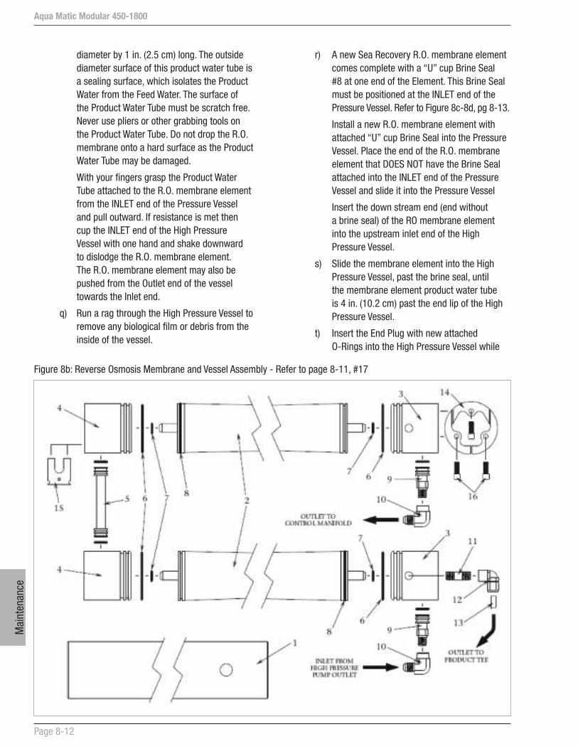
Aqua Matic Modular 450-1800
Page 8-12
Mai
nten
ance
r) A new Sea Recovery R.O. membrane element comes complete with a “U” cup Brine Seal #8 at one end of the Element. This Brine Seal must be positioned at the INLET end of the Pressure Vessel. Refer to Figure 8c-8d, pg 8-13.
Install a new R.O. membrane element with attached “U” cup Brine Seal into the Pressure Vessel. Place the end of the R.O. membrane element that DOES NOT have the Brine Seal attached into the INLET end of the Pressure Vessel and slide it into the Pressure Vessel
Insert the down stream end (end without a brine seal) of the RO membrane element into the upstream inlet end of the High Pressure Vessel.
s) Slide the membrane element into the High Pressure Vessel, past the brine seal, until the membrane element product water tube is 4 in. (10.2 cm) past the end lip of the High Pressure Vessel.
t) Insert the End Plug with new attached O-Rings into the High Pressure Vessel while
diameter by 1 in. (2.5 cm) long. The outside diameter surface of this product water tube is a sealing surface, which isolates the Product Water from the Feed Water. The surface of the Product Water Tube must be scratch free. Never use pliers or other grabbing tools on the Product Water Tube. Do not drop the R.O. membrane onto a hard surface as the Product Water Tube may be damaged.
With your fingers grasp the Product Water Tube attached to the R.O. membrane element from the INLET end of the Pressure Vessel and pull outward. If resistance is met then cup the INLET end of the High Pressure Vessel with one hand and shake downward to dislodge the R.O. membrane element. The R.O. membrane element may also be pushed from the Outlet end of the vessel towards the Inlet end.
q) Run a rag through the High Pressure Vessel to remove any biological film or debris from the inside of the vessel.
Figure 8b: Reverse Osmosis Membrane and Vessel Assembly - Refer to page 8-11, #17

Aqua Matic Modular 450-1800
Page 8-13
Maintenance
WARNING: Anytime the valve stem and or Motor gear shaft is rotated separately from the other they must be replaced. If the coupler set screws have become loose allowing the shafts to rotate independently, or if repair has been performed where in the valve has been separated from the coupler or the motor gear shaft, then the motor gear shaft and the valve stem MUST BE REPLACED. If the valve stem has rotated separately from the motor gear shaft the control logic will not be able to maintain and control the system operating pressure.
A) Motor Function Test
Perform a Function Test on the Electric Motor Actuator as described in Section 6.4.
WARNING: DO NOT BENCH TEST the Electric Motor Actuator. DO NOT APPLY DIRECT VOLTAGE TO THE ACTUATOR. Bench testing of the motor can cause physical damage to the positioning signal device located within the Actuator assembly.
B) Valve Packing Leak
If the Back Pressure Regulator valve leaks from the valve stem, lightly tighten the packing gland nut located below the valve stem. Should adjustment fail to stop the leak, replace the entire valve.
aligning the High Pressure Port and Product Water Port to the respective holes in the High Pressure Vessel. Continue pushing inward on the End Plug until its exposed end travels just past the Segment Ring Groove in the Pressure Vessel. Ensure that the Ports of the End Plug are aligned with the Port Holes of the High Pressure Vessel.
u) Insert the High Pressure Port Fitting with attached O-Rings into the High Pressure Port.
v) Replace the Port Retainer.
w) Insert the three-piece Segment Ring Set into the Segment Ring Groove of the High Pressure Vessel. Align the Segment Ring Set with the tapped holes in the End Plug for insertion of the three Socket Head Cap Screws. Attach the three Socket Head Cap Screws and tighten.
x) Connect the High Pressure Hoses to the respective fitting on the Pressure Vessel.
18. High Pressure Manifold. Replace the High Pressure Manifold if it is visibly cracked or broken and leaking. Replace High Pressure fitting O-rings if damaged, worn, or leaking.
19. High Pressure Transducer: The Pressure Transducers are not repairable and can not be calibrated. If inoperative check connections at the Transducer and at the Printed Circuit Board to ensure there is no visible corrosion or loose connections.
20. Automatic Motor Actuated Back Pressure Regulator: The Motor Actuator and Gear Assembly are not repairable. If the motor has been confirmed to be non operational, replace it.
Figure 8c: R.O. Membrane illustration of brine sealsLeft side: Inlet / Feed Water Entry / R.O. Membrane Element Brine Seal EndRight Side: Outlet / Brine Discharge / No brine seal in this end
Figure 8d: Inlet end of Pressure Vessel / Brine Seal End of R.O. Membane Element

Aqua Matic Modular 450-1800
Page 8-14
Mai
nten
ance
24. Multi Media Filter Waste & Brine Discharge Tee: This 90 degree elbow fitting attaches to the over board thru-hull fitting for connecting the brine discharge hose. If it breaks or cracks replace it.
25. Thru-Hull Discharge Fitting: This Owner or Installer supplied Discharge Thru-Hull Fitting is not repairable. If it breaks or cracks replace it.
26. Product Water T-Collector: The Product Water T-Collector is not repairable. If it breaks or should a crack develop replace it.
27. Salinity Probe: The salinity probe requires cleaning from time to time should debris build up onto the monel probes. Clean the probes once a year.
a) Unscrew the black tube fitting nut below the probe to disconnect it from the control manifold.
b) Using a soft bristle brush, scrub the probes to remove any built up debris. Thoroughly dry the probe area.
c) Should the salinity reading become inaccurate replace it.
28. Product Water Flow Meter: The electronic flow meters used in the System are not repairable. If the flow meter gives an inaccurate reading replace it.
29. 3-way Product Water Diversion Solenoid Valve:
A) Do not assume that the Valve’s Solenoid is not operational. Check it by performing a Function Test as described in Section 6.4.
B) Over tightening of the tube fittings into the valve’s body can cause the Diversion Valve internal ports to move out of proper position resulting in internal blockage or bypassing.
Refer to Figure 8e through 8f, page 8-15 and follow the instructions listed below.
1) Remove Diversion Valve from the system.
2) Position the manual over ride button OUTWARD to normal position by first pushing the button inward and rotating it counter clockwise allowing it to spring outward away from the coil body.
3) With your mouth, blow into port “P”, air should expel from port “B” which is the “normally open” or “bad water” port.
4) If it is extremely difficult to expel air from port “B” or if no air expels from port “B”, then valve needs to be replaced.
CAUTION: DO NOT over tighten the packing gland. Over tightening will cause premature wear and failure of the packing and stem.
WARNING: Over tightening will also cause excessive drag increasing the torque requirement of the valve’s electric motor. Excessive drag resulting in increased torque requirement will cause the valve motor to draw high current. When the valve’s motor draws high current the system Control Logic will stop the system and the touch screen will display an error message.
When the actuator motor starts, it momentarily draws high current (this is normal). Once the motor begins to rotate, with no restrictions, the current lowers to normal running current. The motor, in turn, rotates the gear box, sensing POT (potentiometer) and valve stem.
If the motor movement is blocked or restricted and does not rotate it will draw high current and the sensing POT will not rotate. The System Control Logic receives the high current signal and the lack of sensing POT movement. This results in the stopping of the System and display an error message.
Determine what is restricting the movement of the Valve.
Proceed in this order:
a) Check the brass coupling that connects the valve stem and gear box shaft to ensure it allows free movement and turning.
b) Check for external signs of corrosion or water intrusion into the Actuator housing.
c) Ensure that the Valve Stem packing nut is not over tightened causing friction and resistance.
21. Brine Discharge Flow Meter: The electronic flow meters used in the System are not repairable. If the flow meter gives an inaccurate reading replace it.
22. Brine Discharge T-Connector: The Brine Discharge T-Connector is not repairable. If it breaks or should a crack develop replace it.
23. Brine Discharge Connector: This 90 degree elbow fitting attaches to the over board thru-hull fitting for connecting the brine discharge hose. If it breaks or cracks replace it.
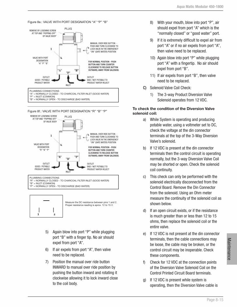
Aqua Matic Modular 450-1800
Page 8-15
Maintenance
5) Again blow into port “P” while plugging port “B” with a finger tip. No air should expel from port “A”.
6) If air expels from port “A”, then valve need to be replaced.
7) Position the manual over ride button INWARD to manual over ride position by pushing the button inward and rotating it clockwise allowing it to lock inward close to the coil body.
8) With your mouth, blow into port “P”, air should expel from port “A” which is the “normally closed” or “good water” port.
9) If it is extremely difficult to expel air from port “A” or if no air expels from port “A”, then valve need to be replaced.
10) Again blow into port “P” while plugging port “A” with a fingertip. No air should expel from port “B”.
11) If air expels from port “B”, then valve need to be replaced.
C) Solenoid Valve Coil Check:
1) The 3-way Product Diversion Valve Solenoid operates from 12 VDC.
To check the condition of the Diversion Valve solenoid coil:
a) While System is operating and producing potable water, using a voltmeter set to DC, check the voltage at the din connector terminals at the top of the 3-Way Diversion Valve’s solenoid.
b) If 12 VDC is present at the din connector terminals then the control circuit is operating normally, but the 3-way Diversion Valve Coil may be shorted or open. Check the solenoid coil continuity.
c) This check can only be performed with the solenoid electrically disconnected from the Control Board. Remove the Din Connector from the solenoid. Using an Ohm meter measure the continuity of the solenoid coil as shown below.
d) If an open circuit exists, or if the resistance is much greater than or less than 12 to 15 ohms, then replace the solenoid coil or the entire valve.
e) If 12 VDC is not present at the din connector terminals, then the cable connections may be loose, the cable may be broken, or the control circuit may be inoperable. Check these components.
f) Check for 12 VDC at the connection points of the Diversion Valve Solenoid Coil on the Control Printed Circuit Board terminals.
g) If 12 VDC is present while system is operating, then the Diversion Valve cable is
Figure 8e.: VALVE WITH PORT DESIGNATION “A” “P” “B”
PLUGREMOVE BY LOSENING SCREW
AT TOP AND “POPPING OFF” OF VALVE BODY
1
VALVE WITH PORT DESIGNATION
“A” “P” “B”
OUTLET GOOD / POTABLE PRODUCT WATER
OUTLET BAD / NOT POTABLE TO PRODUCT WATER REJECT
INLET
MANUAL OVER RIDE BUTTON - PUSH AND TURN CLOCKWISE TO LOCK VALVE IN THE EMERGENCY “ON” (SAFE WATER) POSITION
FOR NORMAL POSITION - PUSH BUTTON AND TURN COUNTER CLOCKWISE TO RELEASE BUTTON OUTWARD, AWAY FROM SALENOID.
PLUMBING CONNECTIONS “A” = NORMALLY CLOSED - TO CHARCOAL FILTER INLET (GOOD WATER)“P” = INLET (COMMON)“B” = NORMALLY OPEN - TO DISCHARGE (BAD WATER)
Figure 8f.: VALVE WITH PORT DESIGNATION “R” “B” “P”
REMOVE BY LOSENING SCREW AT TOP AND “POPPING OFF”
OF VALVE BODY
VALVE WITH PORT DESIGNATION
“R” “B” “P”
OUTLET GOOD / POTABLE PRODUCT WATER
1
OUTLET BAD / NOT POTABLE TO PRODUCT WATER REJECT
INLET
MANUAL OVER RIDE BUTTON - PUSH AND TURN CLOCKWISE TO LOCK VALVE IN THE EMERGENCY “ON” (SAFE WATER) POSITION
FOR NORMAL POSITION - PUSH BUTTON AND TURN COUNTER CLOCKWISE TO RELEASE BUTTON OUTWARD, AWAY FROM SALENOID.
PLUG
PLUMBING CONNECTIONS “R” = NORMALLY CLOSED - TO CHARCOAL FILTER INLET (GOOD WATER)“B” = INLET (COMMON)“P” = NORMALLY OPEN - TO DISCHARGE (BAD WATER)
Measure the DC resistance between pins 1 and 2. Proper resistance reading is aprox. 12 to 15 Ω
Aqua Matic Modular 450-1800
Page 8-16
Mai
nten
ance
loose at one of the connections or the cable is defective.
h) If there is no voltage present while system is operating, then troubleshoot the Control Printed Circuit Board.
30. Charcoal Filter: A sulfurous (rotten eggs) odor from the product water requires the replacement of the Charcoal Element. Otherwise, the Charcoal Element should be replaced every 3 to 4 months. It is not cleanable.
CAUTION: Do not use third party charcoal or carbon filter elements; use only Sea Recovery Charcoal Filter Elements. Many third party Charcoal Filter Elements on the market do not properly fit, the seams fall apart, and they will allow by-pass.
WARNING: Many third party Charcoal and Carbon Filter Elements on the market are designed for a very low flow rate and will cause extensive and expensive damage to the Sea Recovery System resulting from several hundred pounds of pressure build up on the product water line. Excessive pressure resulting from third party Charcoal or Carbon Filter Elements will damage: R.O. Membrane Element, Product Water Flow Meter, 3-Way Product Water Diversion Valve, Charcoal Filter Housing, and the Product Water Line.
DO NOT ACCEPT THIRD PARTY CHARCOAL FILTER ELEMENTS FROM ANY MARINE DEALER. USE ONLY SEA RECOVERY SUPPLIED CHARCOAL FILTER ELEMENTS. The resulting failure of the system to remain in operation, and or damage to the Sea Recovery System caused by Third Party Charcoal or Carbon Filter Elements is attributed to improper maintenance and operation, is the liability of the operator and owner, and is not covered by the Sea Recovery warranty.
To replace the Charcoal Filter Element:
a) Unscrew the bowl counter clockwise.
b) Remove the Charcoal Filter Element from the bowl.
c) Remove the O-Ring from the top of the bowl and take care to not damage it.
d) Replace the Charcoal Filter Element with a new Sea Recovery element.
e) Wipe the O-Ring with a damp cloth.
f) Sparingly lubricate the O-Ring lightly with O-Ring lubricant.
g) Place the O-Ring back onto the bowl.
h) Insert the new, Sea Recovery Charcoal Filter Element into the bowl.
i) Screw the bowl on clockwise.
j) Hand snug to seal the O-Ring, do not use a wrench or other tool to tighten, do not over tighten. Over tightening causes stress to the lid and bowl threads resulting in damage, breakage, or cracks and subsequent removal difficult.
31. pH Neutralizing Filter: The pH Neutralizing cartridge will require replacement when the calcium carbonate within the cartridge has dissolved.
To replace the pH Neutralizing Cartridge:
a) Unscrew the bowl counter clockwise.
b) Remove the pH Neutralizing Cartridge from the bowl.
c) Remove the O-Ring from the top of the bowl and take care to not damage it.
d) Replace the pH Neutralizing Cartridge with a new Sea Recovery Cartridge.
e) Wipe the O-Ring with a damp cloth.
f) Sparingly lubricate the O-Ring lightly with O-Ring lubricant.
g) Place the O-Ring back onto the bowl.
h) Insert the new, Sea Recovery pH Neutralizing Cartridge into the bowl.
i) Screw the bowl on clockwise.
j) Hand snug to seal the O-Ring, do not use a wrench or other tool to tighten, do not over tighten. Over tightening causes stress to the lid and bowl threads resulting in damage, breakage, or cracks and subsequent removal difficult.

Aqua Matic Modular 450-1800
Page 8-17
Maintenance
32. Ultraviolet Sterilizer: The UV Sterilizer lamp emits a low frequency form of light. This light degrades and loses intensity and ability to sterilize biological matter over approximately 8,000 hours of use. Therefore, the lamp may remain lit, but requires replacement every 4400-8000 hrs.
CAUTION: Make sure that system power is turned off before beginning sterilizer maintenance. Ultra Violet light is harmful to eyes and skin.
Lamp Replacement:
a) Remove the four screws on the ballast box and remove lid.
b) Remove the rubber boot and carefully pull lamp out of the quartz sleeve.
c) Replace the lamp. During lamp replacement clean the quartz sleeve as well. The quartz sleeve should be crystal clear and if it has discolored, it must be cleaned or replaced.
Quartz Sleeve Cleaning:
a) Remove the four screws on the ballast box and remove lid.
b) Remove the rubber boot and carefully pull lamp out of the quartz sleeve.
c) Unscrew and remove the two compression nuts (ballast box and view port).
d) Remove the O-ring on the view port side only.
e) With care pull the quartz sleeve out from the ballast box side.
f) Clean the quartz tube with water and a bottle brush without moving the O-ring. Dry with a soft cloth. Handle the quartz sleeve carefully.
Reassembly:
a) Replace old O-rings with new O-rings.
b) Insert the quartz sleeve (close-end first) through the ballast box passthru until O-ring contact passthru. Screw on the ballast box compression nut. Insert view port O-ring and screw on view port compression nut..
c) Attach a new UV Lamp into the plug.
d) Slide the lamp into the Quartz Sleeve and install rubber boot over the compression nut.
e) Replace the three 1/4-20 cap head screws.
33. Fresh Water Flush Carbon Filter Element: The Carbon Filter Element in the Fresh Water Flush should be replaced every 3 months.
The Fresh Water Flush will automatically flush the system with Fresh Water every preset number of days. The duration of the flush cycle will be 90 seconds for a system connected to 60 Hz power and to 120 seconds for systems connected to 50 Hz power.
To replace the Carbon Filter Element:
a) Unscrew the bowl counter clockwise.
b) Remove the Carbon Filter Element from the bowl.
c) Remove the O-Ring from the top of the bowl and take care to not damage it.
d) Replace the Carbon Filter Element with a new Sea Recovery element.
e) Wipe the O-Ring with a damp cloth.
f) Sparingly lubricate the O-Ring lightly with O-Ring lubricant.
g) Place the O-Ring back onto the bowl.
h) Insert the new, Sea Recovery Carbon Filter Element into the bowl.
i) Screw the bowl on clockwise.
j) Hand snug to seal the O-Ring, do not use a wrench or other tool to tighten, do not over tighten. Over tightening causes stress to the lid and bowl threads resulting in damage, breakage, or cracks and subsequent removal difficult.

Aqua Matic Modular 450-1800
Page 8-18
Mai
nten
ance
Unit Maintenance
The exterior surfaces of the UV unit should be kept clean and dry. In most cases it may be necessary to clean the exterior of the unit once a month. Use soft cloth and soapy water, or any commercial stainless steel cleaner.
Interior of the ballast box should be inspected for debris. Any debris should be removed using vacuum.
Quartz Sleeve
Debris and other matter in the water will settle onto the quartz sleeve and eventually block the ultraviolet rays from penetrating into the water. It is necessary to determine a cleaning schedule for the quartz sleeve. The frequency will depend on the specific type of water being processed and the duty cycle of the unit.
Inspect the quartz sleeve 30 days after initial installation to assess the amount of contamination collected over the 30-day period. Use the finding to determine a reasonable schedule and frequency for periodic cleaning.
Clean-In-Place (CIP) cleaning is sometimes effective in removing debris from the quartz sleeve. Conduct a CIP cleaning test to determine its effectiveness. If CIP cleaning is not effective, then a manual cleaning or replacement is required.
When the quartz sleeve is due for cleaning, use the following procedures.
1. Turn off the water source to the UV unit.
2. Disconnect the power source to the UV unit.
3. Drain the UV treatment chamber.
4. Remove the ballast box cover.
5. Remove rubber boot and carefully pull out the UV lamp through the compression nut pass-thru.
6. Use a channel lock to remove the compression nuts.
7. Remove the Quartz Sleeve carefully.
8. Wash the Quartz Sleeve with mild soapy water and rinse in clean hot water.
If dirt remains after rinsing, the quartz sleeve should be replaced. Contact your local CSR to order a replacement.
NOTE! Failure to perform quartz sleeve maintenance may reduce the efficiency of the UV light to adequately treat water in the treatment chamber.
8.4 UV STERILIZER MAINTENANCE
Follow the preventative maintenance procedures to maximize the efficiency, reliable, and longevity of the UV Sterilizer.
Refer to Table on Page 8-17 for recommended maintenance schedule.
WARNING! The most important consideration is operator safety. The following directly relates to operator safety. All personnel must review and comply with the following.
CAUTION! Operators must observe Safety Requirements at all times
Safety Requirements
The following safety requirements are mandatory. Failure to comply can cause injuries and/or damages to the UV unit.
1. Never look directly at the blue ultraviolet lamp when it’s “ON”. Never operate the ultraviolet lamp outside the stainless steel cabinet. UV light exposure can severely burn and damage eyes and skin.
2. Properly ground the UV unit. Failure to properly ground the UN unit can cause severe electrical shock hazard.
3. Provide watertight piping and compression nut seals. Failure to provide watertight seals can cause damage to electrical components or cause electrical shock hazard.
4. Disconnect power before servicing the UV unit. The UV lamp and electrical components operate with high voltage electrical power. Do not attempt to service the UV unit without first disconnecting the power source. Shut off the source of power at the main panel breaker and use appropriate tag-out or lock-out procedures to prevent accidental power-up.
5. Only qualified service personnel should perform services to the UV unit.
6. Remove pressure before servicing the UV unit.
7. Never operate the UV unit for more than 30 minutes without water flow. Elevated water temperature can damage the UV unit.
8. Do not exceed 3 “Start/Stop” cycles per 24-hour period. Exceeding 3 cycles will subjected the lamp filament to excessive thermal stress leading to premature failure of the UV lamp.

Aqua Matic Modular 450-1800
Page 8-19
Maintenance
NOTE! Sea Recovery recommends a valve with a discharge orifice not to exceed ¼” (6mm).
Sampling Procedure
Use sterile sample bottles obtained from reliable laboratory that has been autoclaved and kept in plastic bag for this procedure.
1. Use temporary tube to direct water from UV unit to container or drainage.
2. Pressurize the UV unit and flush unit with sample valve fully opened for 3.5 minutes. After flushing for 3.5 minutes, reduce valve opening to 50% and flush for 3 minutes.
3. Open the sample bottle and keep the inside of the cap facing down.
4. Fill the sample bottle and avoid breathing directly into the bottle or touching the inside of the bottle, cap, or neck.
5. Immediately cover and secure the cap after filling the sample bottle.
6. Label the sample bottle and place in a clean plastic bag.
7. Take sample bottle to the laboratory for plating as soon as possible.
NOTE! Sample processing must begin within 3 hours after sample collection and must comply with accepted standard methods.
Checking for Leaks
Visual inspect the UV unit exterior for signs of leakage. The cause of any leakage must be located and repaired.
If a leakage is detected, perform the following.
1. Shut off all electrical power. Shut off the source of power at the main panel breaker and use appropriate tag-out procedures to prevent accidental power-up.
2. Depressurize the UV unit.
3. Remove ballast box cover and remove the rubber boot.
4. Locate which end of the quartz sleeve is leaking.
Repairing Leaks
If both ends of the quartz sleeve are leaking, perform the following on both ends.
1. Use a channel lock to loosen and remove the compression nut.
2. Remove the quartz sleeve O-ring without pulling the quartz sleeve out.
3. Lubricate the quartz sleeve tip with clean water and place new O-ring. Ensure the O-ring has all-round contact with the cylinder pass-thru.
4. Replace and tighten the compression nut.
5. Refill the treatment chamber and verify a leak-free condition.
Measuring Performance
Every UV unit must be tested periodically to verify its efficiency. Regardless of the intended application or any optional equipment provided with the UV unit, the most accurate procedure is the Post-UV Analysis. The Post-UV Test must be performed in accordance with standard testing methods.
Verifying Lamp Operation
The UV lamp is “ON” when the blue light is emitting thru the viewport.
Obtaining Water Samples
Vast majority of unsatisfactory Post-UV Test results are directly related to the improper sample-taking techniques. Although several commercial sample collection apparatuses are available, the proper manufacturer’s sample procedures must be followed.

Aqua Matic Modular 450-1800
Page 8-20
Mai
nten
ance
Periodic Maintenance Table
The table below represents the recommended Periodic Maintenance (PM) for the SP Series UV Unit.
Description Init. Daily Mn Ann. Other
Quartz Sleeve Cleaning x
Quartz Sleeve Replacement* x
Operating Condition x
Unit Cleaning x x
Leak Inspection x x x
UV Lamp Inspection x x x
UV Lamp Replacement-SP-1 x 4,400 hrs
UV Lamp Replacement-SP-2 x 8,000 hrs
* Quartz Sleeve replacement will occur more frequently for systems operating with continuous high flow rate or low water quality water, and less frequently for systems operating with low flow rate or high water quality.
UV Unit Specifications
Type 12 VDC Operating UV Sterilizer for 2 gallon (7.5 liters) per minute of water flow
Ballast Type Solid State
Bulb Type 16 Watts Single Ended
Bulb Life 8000 Hours minimum
Materials Body: SS304; Ballast Box: PVC
Power Cord 13 ft. (4 meters) 2 conductors
Weight 1 lbs. (500g) Body
Temperature Range Operating: +37ºF to +104ºF (+3ºC to +40ºC); Dry Storage: -4ºF to +185ºF (-25ºC to +85ºC)
Operating Voltage Range 10.56V minimum; 16.50V maximum
Current 1.45A maximum @ Standard Test Voltage
UV Dosage 22mJ/cm2 @ 254nm
Operating Pressure 50psi (3.4 bar)
Inlet/Outlet Ports ¼ in. (6.3 mm) NPT Female
Flow Rate 2 gpm (7.5 lpm)
Disinfection Rate 99%
Troubelshooting
Aqua Matic Modular 450-1800
Section 9 - TROUBLESHOOTING

Trou
bels
hoot
ing

Aqua Matic Modular 450-1800
Page 9-1
Troubleshooting
expose the technician to High Voltage and electrical shock hazard. Only attempt this if you are a qualified electrician and only if surrounding conditions are safe.
From time to time, Sea Recovery may make changes to the Control Logic.
Other production changes are tracked by Sea Recovery through the System Serial Number.
Troubleshooting methods and results can vary depending on the information that is displayed at the SYSTEM INFORMATION screen.
Whenever requesting assistance from Sea Recovery or one of Sea Recovery’s service dealers:
ALWAYS PROVIDE ALL INFORMATION DISPLAYED AT THE SYSTEM INFORMATION SCREEN.
9.1 ALARM AND ERROR SCREENS
The following alarm and error screens provide operator information regarding the condition of the System. Where applicable, the alarm message (yellow background) or error message (red background) will recommend the corrective action to eliminate the system alarm or error.
9 TROUBLESHOOTING
This section deals with abnormal occurrences of the System. Some occurrences may have many different causes. For each symptom, one or more causes are given. In turn, each cause has one or more corresponding tests to help identify whether the cause of the occurrence is the correct one. When the test has confirmed the source of the problem, the appropriate remedy is given to correct it.
There may be more than one cause of a problem. In the following guide, when there is more than one cause of a problem, the causes are listed in the most likely to occur order. The tests given are designed to determine whether the cause of the problem is the correct one. When diagnosing the causes of a problem in this case, eliminate the listed causes one by one until the correct cause is found. Then the appropriate remedy is performed. Diagnosing and correcting the various occurrences in this manner makes troubleshooting easier and less time consuming.
Troubleshooting and subsequent correction or repair will require understanding of:
a) Electrical Circuits
b) Electronic Circuits
c) Electric Motors
d) Hydraulic Systems
e) Liquid Pressures and Flows
f) Electromechanical Systems
g) Mechanical knowledge and skills
WARNING! Do not attempt troubleshooting and/or subsequent correction or repair if you are not familiar with or are not proficient in the above fields of expertise.
**USE CAUTION WHEN TROUBLESHOOTING**
DO NOT PERFORM MAINTENANCE UNLESS:
a) The System Feed Water Sea Cock Valve is closed.
b) The electrical power to the system is switched “OFF”, LOCKED, and TAGGED.
c) Section 10, “EXPLODED PARTS VIEW” is available.
CAUTION!: ELECTRICAL SHOCK HAZARD. A Volt / Ohm Meter will be necessary. The following procedures
Aqua Matic Modular 450-1800
Page 9-2
Trou
bles
hoot
ing
9.2 TROUBLESHOOTING COMPONENTS
Refer to the P&ID in Section 3.
Blockage at the Inlet Thru-Hull Fitting causes the System to shut off due to lack of Feed Water Flow. This can cause time consuming frustrations in attempting to gain feed water flow by trouble shooting other components in the System.
The Inlet Thru-Hull Fitting must be free and clear allowing the System to draw 4.5 U.S. GPM (17 LPM) through it with minimal resistance. This Inlet Thru-Hull Fitting must be a Forward Facing Scoop so that the System receives a positive flow of water as the boat is under way. It must be minimum 3/4 in. (1.9 cm) inside diameter. It must be installed in a position on the bottom of the Hull so as to allow free flowing Feed Water without air.
CAUTION! A flat profile, flush mount, inlet thru-hull fitting will cause a vacuum as the boat is under way, and this will cause loss of feed water flow and cavitation of the Booster Pump and High Pressure Pump resulting in continual system shut down due to low feed water flow and pressure. The resulting failure of the system to remain in operation is attributed to improper installation, is the liability of the installer, and is not covered by the Sea Recovery warranty.
CAUTION! If the thru-hull fitting has been placed in a position on the underside of the hull that allows air to continually enter the thru-hull fitting, this will cause the system to continually shut down due to loss of feed water. The resulting failure of the system to remain in operation is attributed to improper installation, is the liability of the installer, and is not covered by the Sea Recovery warranty.
CAUTION! The Sea Recovery System must not be tied into another existing auxiliary water line already supplying another accessory on the boat. Using one Thru Hull fitting for other equipment will cause the Sea Recovery System to draw air or cavitate leading to continual system shut down. The resulting failure
1. Fresh Water Tank full.
2. Product flow was out of specifications. Check for leaks and wiring connections.
3. Conductivity sensor (#) failed measuring. Check wiring.
4. Fresh Water Tank was too low. Fresh Water Flush stopped.
5. Flow error in the Fresh Water Flush Operation. Check for leaks or blockage in the Fresh Water Supply.
6. Product flow is low. Check water temperature and reverse osmosis membrane.
7. Unable to communicate with the selected watermaker. Check the water maker.
8. The TDS salinity level at the product water line is too high. The system is unable to clean the water. Check for mechanical failure.
9. Pressure drop on inlet Filters to excessive. Check filters.
10. User initiated emergency break.
11. Power has been interrupted while the system was in operation. The system will not restart automatically.
12. Inlet Pressure of the High Pressure Pump dropped below specifications. Check Booster Pump and filters.
13. Outlet pressure of High Pressure Pump exceeded the specifications. Check Brine Discharge, Product Water lines and Post Filtration.
14. Brine Discharge flow was out of specifications. Check for leaks and wiring connections.
15. Back Pressure Regulator is stuck. Check for a mechanical failure and wiring connections.
16. Warning on the watermaker. For detailed information please check warning on the watermaker display.
17. Alarm on the watermaker. For detailed information please check alarm on the watermaker display
18. Low Pressure Sensor (#) failed to measure the pressure. Check wiring.
19. High Pressure sensor failed to measure the pressure. Check wiring.
20. Temperature Sensor (#) failed to measure the temperature. Check wiring.
Aqua Matic Modular 450-1800
Page 9-3
Troubleshooting
Solution: Clean all marine growth and debris from the Inlet Thru-Hull Fitting.
System is newly installed and operation is being performed for the first time. The feed water pressure is low and insufficient to keep the System in operation.
A NEW boat, or newly installed System, may have protective shipping tape covering the Inlet Thru-Hull Fitting. A New boat, or newly installed System, may have manufacturing debris such as caulking slopped over the Inlet Thru Hull or a rag may be stuffed into the Inlet Thru-Hull fitting. A NEW Inlet Thru-Hull Fitting may have casting slag, that has not been machined off, partially covering the “fingers” or the inside of the fitting.
Solution: Inspect the Inlet Thru-Hull Fitting and clean all manufacturing debris and casting slag from the fitting.
2) SEA COCK VALVE
The Sea Cock Valve is usually a 1/4 turn Ball Valve although any positive closing and opening valve is acceptable.
Problems and Symptoms appearing and caused by the SEA COCK VALVE:
a) The Sea Cock Valve is closed when attempting to Start the System.
System does not register feed water flow and feed water pressure when attempting to start. An error screen appears and the System shuts down.
When the System is not in use it is good practice, for the safety of the Boat, to close the Sea Cock Valve. Don’t forget to open it prior to starting the System.
Solution: Open the Sea Cock Valve.
b) The Sea Cock Valve seal is worn or the seal is loose causing air to enter the System Feed Line.
System feed water pressure is low and insufficient to keep the System in operation. This section of the Feed Line is under a vacuum condition when the System is in operation. If the valve’s seal is worn or loose air can enter the feed line causing the System to lose pressure.
Look for air bubbles moving through the Sea Strainer, or feed line.
Solution: Change the valve seals, tighten them, or if necessary replace the valve.
of the system to remain in operation is attributed to improper installation, is the liability of the installer, and is not covered by the Sea Recovery warranty.
CAUTION! If the Sea Recovery System is connected to a Sea Chest or Stand Up Pipe, do not plumb the Sea Recovery System feed line to the “top” of the Sea Chest or Stand Up Pipe. If plumbed into the top of these feed water arrangements, the Sea Recovery System will experience continual shut down due to air inducement into the system. The resulting failure of the system to remain in operation is attributed to improper installation, is the liability of the installer, and is not covered by the Sea Recovery warranty. Plumb the Sea Recovery System to the “bottom” of such feed water arrangements to ensure a continual air free supply of feed water to the system.
1) THRU-HULL INLET FITTING
Problems and Symptoms appearing and caused by the THRU-HULL INLET FITTING:
a) Flat profile Inlet Thru Hull Fitting:
System runs fine when at anchor. However, when under way the System shuts off due to low pressure or low feed water flow.
A flat profile Inlet Thru Hull Fitting will cause a vacuum at the System’s feed line cavitating the Booster Pump and reducing the efficiency of the Booster Pump resulting in low feed water pressure and low feed water flow.
Solution: Change the flat profile Thru Hull Fitting to a forward facing scoop.
b) Debris is blocking the Inlet Thru Hull Fitting:
System feed water pressure is low and insufficient to keep the System in operation.
Marine growth or debris such as a plastic bag or rag covering the Inlet Thru-Hull Fitting will cause a vacuum at the System’s feed line cavitating the Booster Pump and reducing the efficiency of the Booster Pump resulting in low feed water pressure and low feed water flow.

Aqua Matic Modular 450-1800
Page 9-4
Trou
bles
hoot
ing
the System is in operation. If the Sea Strainer O-Ring is not properly seated air will enter the feed line causing the System to loose pressure.
Look for air bubbles moving through the Sea Strainer and into the Feed Line.
Solution: Properly seat or replace the Sea Strainer O-Ring.
b) The Sea Strainer mesh screen element is the first line of defense to trap large suspended solids entering the Feed Line. Depending on Feed Water conditions the screen may plug up rapidly. Marine growth, plastic bags, jelly fish, and other debris can easily enter the feed line and plug up the Sea Strainer mesh screen.
System feed water pressure is low and insufficient to keep the System in operation because the Sea Strainer mesh screen is blocking feed water flow.
Solution: Regularly check and clean the Sea Strainer mesh screen. Keep it clear and free of debris.
6) BOOSTER PUMP
The Booster Pump is a centrifugal type pump. When mounted at or below feed water level it is able to draw feed water and deliver it with pressure into the prefiltration components and High Pressure Pump. If mounted above feed water level the Booster Pump may have trouble priming if air enters the feed line.
Prior to assuming that the Booster Pump’s Electric Motor has failed, perform a Function Test as described in Section 6.
Problems and Symptoms appearing and caused by the Booster Pump:
a) The Booster Pump leaks feed water between the pump and motor.
The Booster Pump has a ceramic and carbon seal. Ceramic and carbon seals will weep if the pump is not operated for extended periods of time. When used regularly the seal will give approximately 2000 hours of use. The seal continually wears during use and must be replaced approximately every 2000 hours of use. If left unused for extended periods of time seal replacement may be required sooner.
Solution: Replace seal.
3) INLET CONNECTOR
AS WELL AS ALL FITTINGS AND CONNECTIONS PRIOR TO THE INLET OF THE BOOSTER PUMP:
Problems and Symptoms appearing and caused by any fitting or connection in the Suction portion of the Feed Line:
a) One or more fittings or connections in the Suction portion of the Feed Line is causing air to enter the Feed Line.
System feed water pressure is low and insufficient to keep the System in operation. This section of the Feed Line is under a vacuum condition when the System is in operation.
Look for air bubbles moving through the Sea Strainer, or feed line.
Solution: Tighten any loose fitting or connection at the Inlet of the Booster Pump or prior to it that is allowing air to enter the feed line.
Replace worn or broken seal or O-ring at the Inlet of the Booster Pump or prior to it that is allowing air to enter the feed line.
Check positioning of all valves at or prior to the Inlet of the Booster Pump that may be allowing air to enter the feed line.
4) INLINE VACUUM / PRESSURE GAUGES
Problems and Symptoms appearing and caused by the Inline Vacuum/Pressure Gauges:
a) A Vacuum/Pressure gauge needle does not move; or does not register proper vacuum or pressure.
The Vacuum/Pressure Gauges have a very small orifice at the bottom of the pipe fitting end. This orifice can become plugged with debris or corrosion.
Solution: Using a small diameter wire clean the debris from the orifice.
5) SEA STRAINER
Problems and Symptoms appearing and caused by the Sea Strainer:
a) The Sea Strainer O-Ring seal is not properly seated, is worn, or is not properly compressed allowing air to enter the Feed Line.
System feed water pressure is low and insufficient to keep the System in operation. This section of the Feed Line is under a vacuum condition when

Aqua Matic Modular 450-1800
Page 9-5
Troubleshooting
9) PLANKTON FILTER
This optional filter assembly contains a cleanable ultra fine monel mesh screen. The mesh screen traps suspended solids or biological growth such as plankton. It also provides longer life to the Pre-filter Elements and in turn provides lower system maintenance costs. As with all prefiltration components the Plankton Filter mesh screen must be free of debris in order for the Feed Water to flow through it.
Problems and Symptoms appearing and caused by the Plankton Filter:
a) The Feed Water Pressure into the Plankton Filter is higher than normal, and the Feed Water Pressure into the High Pressure Pump is lower than normal.
The pressure differential readings across the Plankton Filter indicate that the element is filled with debris blocking the feed water.
Solution: Clean the Plankton Filter Element.
10) MULTI MEDIA FILTER
This optional filter assembly contains a back-washable bed of sand and gravel. The sand traps suspended solids larger than 30 microns which provides longer life to the pleated cartridge prefilter elements minimizing maintenance intervals, maintenance labor, and filter element cost. Pressure and flow will be restricted as the sand bed becomes clogged with debris and marine growth. The sand bed is washable by reversing the feed water flow across it. This process is referred to as Back Washing.
Problems and Symptoms appearing and caused by the Plankton Filter:
a) The Feed Water Pressure into the Multi Media Filter is higher than normal, and the Feed Water Pressure into the High Pressure Pump is lower than normal.
The pressure differential readings across the Multi Media Filter indicate that the Multi Media Filter requires back washing.
Solution: Back wash the Multi Media Filter.
11) DUAL PRE-FILTER
This two stage filter removes suspended solids first through a 20 micron cartridge filter element then through a 5 micron cartridge filter element. By stepping the filtration both prefilter elements gain longer life and require less maintenance labor and prefilter element
7) T-CONNECTOR PRESSURE PICK-UP
Booster Pump Outlet/Prefilter Inlet for line pressure pick up to Low Pressure Transducer #1 between the outlet of the Booster Pump and the inlet of the first prefiltration component.
Problems and Symptoms appearing and caused by the T-Connector Pressure Pick-Up:
a) The Low Pressure Transducer #1 does not register pressure.
The 1/4 in. (5 mm) O.D. tube connecting the T-Connector to the Low Pressure Transducer Manifold may become kinked or debris may block the tube.
Solution: Replace any hose or tube that is kinked. Disconnect each end of the tube and blow air through the tube to ensure that it is not blocked.
8) LOW PRESSURE TRANSDUCER #1
Booster Pump Outlet or 1st Prefilter Inlet for line pressure pick up from the Outlet of the Booster Pump to the Inlet of the 1st Prefiltration component.
The Low Pressure Transducer sends a DC voltage signal to the System Control Logic. The minimum value is .5 VDC when no pressure is applied to it, and the maximum value that the System will accept is 4.5 VDC. The variation of voltage output from the Transducer is converted to pressure value by the System Control Logic.
Problems and Symptoms appearing and caused by the Low Pressure Transducer #1:
a) The Low Pressure Transducer #1 does not register pressure or the pressure displayed is inaccurate.
The 1/4 in. (5 mm) O.D. tube connecting the T-Connector to the Low Pressure Transducer Manifold may become kinked or debris may block the tube.
Solution: Replace any hose or tube that is kinked. Disconnect each end of the tube and blow air through the tube to ensure that it is not blocked.
The pressure readings at the Touch Pad are inaccurate. The minimum voltage output is below .5VDC and or the maximum voltage output is above 5 VDC.
Solution: Check wiring and connections to and from the Transducer. Replace the Transducer.

Aqua Matic Modular 450-1800
Page 9-6
Trou
bles
hoot
ing
The pressure differential readings across the Prefilter indicate that the elements are filled with debris blocking the feed water.
Solution: Replace the Prefilter Elements.
12) COMMERCIAL PRE-FILTER
The Commercial Prefilter housing contains a 5 micron cartridge filter element that has 38 square feet of filtering surface area. This over size cartridge provides extended life that greatly reduces maintenance and prefilter element replacement cost. As the cartridge filter element becomes plugged up with debris pressure and flow drop resulting is System shut down due to low pressure into the High Pressure Pump. The cartridge filter element may be cleaned once to gain approximately 50% of the original life. After the first cleaning it must be discarded and replaced with a new element.
WARNING!: PREFILTER ELEMENT Do not use third party prefilter elements, use only Sea Recovery prefilter elements. Third party prefilter elements do not properly fit and the seams fall apart. They also allow by-pass resulting in premature fouling of the R.O. membrane element and extensive damage to the High Pressure Pump. Damage to the Sea Recovery System caused by the use of third party, non Sea Recovery, Prefilter Elements is the responsibility and liability of the operator and not covered by the Sea Recovery Warranty.
CAUTION! Finger tighten the lid locking ring onto the base. DO NOT over tighten. DO NOT use any wrench or device to tighten the lid locking ring. The lid is O-ring sealed, two finger tightening is adequate. Over tightening will stress the threads on the base and the lid locking ring causing them to crack.
Problems and Symptoms appearing and caused by the Prefilter:
a) The Feed Water Pressure into the Prefilter is higher than normal, and the Feed Water Pressure into the High Pressure Pump is lower than normal.
replacement cost. As the cartridge filter elements become plugged up with debris pressure and flow drop resulting in System shut down due to low pressure into the High Pressure Pump. The cartridge filter elements may be cleaned once to gain approximately 50% of the original life. After the first cleaning they must be discarded and replaced with new elements.
WARNING!: PREFILTER ELEMENT Do not use third party prefilter elements, use only Sea Recovery prefilter elements. Third party prefilter elements do not properly fit and the seams fall apart. They also allow by-pass resulting in premature fouling of the R.O. membrane element and extensive damage to the High Pressure Pump. Damage to the R.O. membrane element or High Pressure Pump caused by the use of third party, non Sea Recovery, Prefilter Elements is the responsibility and liability of the operator and not covered by the Sea Recovery Warranty.
CAUTION!: PREFILTER ELEMENT Do not use “string wound” or “fiber” prefilter elements. These types of elements are designed for the Photographic Film Developing Industry. When used in sea water, they will plug up rapidly in 1/10th or less the time. This will cause frequent shut downs of the system and very frequent changing which will result in very high cost of maintenance and user frustration.
CAUTION! Hand tighten the bowl onto the filter top housing. DO NOT over tighten. DO NOT use any wrench or device to tighten the bowl. It is O-ring sealed, hand tightening is adequate. Over tightening will stress the bowl and top causing it to crack.
Problems and Symptoms appearing and caused by the Prefilter:
a) The Feed Water Pressure into the Prefilter is higher than normal, and the Feed Water Pressure into the High Pressure Pump is lower than normal.
Aqua Matic Modular 450-1800
Page 9-7
Troubleshooting
The 1/4 in. (5 mm) O.D. tube connecting the T-Connector to the Pressure Differential Transducer may become kinked or debris may block the tube.
Solution: Replace any hose or tube that is kinked. Disconnect each end of the tube and blow air through the tube to ensure that it is not blocked.
The pressure readings at the Touch Pad are inaccurate. The minimum voltage output is below .5VDC and or the maximum voltage output is above 5 VDC.
Solution: Check wiring and connections to and from the Transducer. Replace the Transducer.
15) OIL/WATER SEPARATOR
The Oil/Water Separator housing contains a 10 micron coalescing filter element. This Oil/Water Separator is positioned after the Prefilter in the Feed Water Line. Unlike a conventional cartridge filter element, the water flow is into the center and out ward. The purpose of this filter is to coalesce and trap oil so that it doesn’t reach the R.O. membrane element. Oil will permanently foul the R.O. membrane element.
WARNING! OIL/WATER SEPARATOR ELEMENT: Do not use third party Oil/Water Separator elements, use only Sea Recovery supplied elements. Third party elements do not properly fit and will not adequately coalesce the oil from the feed water. They also allow by-pass resulting in premature fouling of the R.O. Membrane Element and extensive damage to the High Pressure Pump. Damage to the Sea Recovery System caused by the use of third party, non Sea Recovery, Oil/Water Separator Elements is the responsibility and liability of the operator and not covered by the Sea Recovery Warranty.
CAUTION! Finger tighten the lid locking ring onto the base. DO NOT over tighten. DO NOT use any wrench or device to tighten the lid locking ring. The lid is O-ring sealed, two finger tightening is adequate. Over tightening will stress the threads on the base and the lid locking ring causing them to crack.
The pressure differential readings across the Prefilter indicate that the element is filled with debris blocking the feed water.
Solution: Replace the Prefilter Element.
13) T-CONNECTOR PRESSURE DIFFERENTIAL PICK-UP
The T Connector is for line differential pressure pick up between optional prefiltration components to the Differential Pressure Transducer #3. This Transducer allows the operator to determine exactly which prefiltration component requires servicing.
Problems and Symptoms appearing and caused by the T-Connector Pressure Pick-Up:
a) The Pressure Differential Transducer does not register pressure.
The 1/4 in. (5 mm) O.D. tube connecting the T-Connector to the Low Pressure Transducer Manifold may become kinked or debris may block the tube.
Solution: Replace any hose or tube that is kinked. Disconnect each end of the tube and blow air through the tube to ensure that it is not blocked.
14) PRESSURE DIFFERENTIAL TRANSDUCER
The Pressure Differential Transducer for line pressure reading across (between) prefiltration components allowing the operator to determine which prefiltration component requires servicing.
The Pressure Differential Transducer sends a DC voltage signal to the System Control Logic. The minimum value is .5 VDC when no pressure is applied to it, and the maximum value that the System will accept is 4.5 VDC. The variation of voltage output from the Transducer is converted to pressure value by the System Control Logic.
Problems and Symptoms appearing and caused by the Pressure Differential Transducer:
a) The Pressure Differential Transducer does not display on the Touch Screen.
Solution: Refer to Section 6 to Set Up and Inform the System Control Logic that the Pressure Differential Transducer has been installed and connected.
b) The Pressure Differential Transducer does not register pressure or the pressure displayed is inaccurate.
Aqua Matic Modular 450-1800
Page 9-8
Trou
bles
hoot
ing
The pressure readings at the Touch Pad are inaccurate. The minimum voltage output is below 0.5 VDC and or the maximum voltage output is above 5 VDC.
Solution: Check wiring and connections to and from the Transducer. Replace the Transducer.
18) TRANSDUCER MANIFOLD
The Transducer Manifold must be replaced if broken and allowing leakage.
19) STANDARD HP PUMP ASSEMBLY
The Electric Motor is 3 horse power, Totally Enclosed Fan Cooled, 2 pole, dual Cycle, and dual Voltage.
WARNING! The High Pressure Pump MUST rotate in the COUNTER CLOCKWISE DIRECTION ONLY. Rotating the High Pressure Pump in the clockwise direction will cause extensive damage to it. Never operate the High Pressure Pump in the clockwise direction.
WARNING! When switching from Three Phase Generator power to Three Phase Shore power ALWAYS check phases prior to operating the System else Reverse Rotation along with extensive damage to the High Pressure Pump will occur should the power be out of phase.
This High Pressure Pump is a Quintiplex Radial Axial Positive Displacement Plunger Pump made of high grade Duplex material specifically designed for sea water Reverse Osmosis applications. The Pump is connected to the attached electric motor with a flex coupler and safety bell housing.
As with all Positive Displacement pumps it must receive a specified minimum amount of water at a positive pressure. A vacuum at the inlet of the pump will cause cavitation and damage. This pump does not use oil, it is self lubricated with the feed water. Internal components are designed for 8,000 hours of continual service in sea water. As with any component exposed to sea water, use is best.
Problems and Symptoms appearing and caused by the High Pressure Pump or its Electric Motor:
Prior to assuming that the High Pressure Pump’s Electric Motor has failed, perform a Function Test.
Problems and Symptoms appearing and caused by the Oil/Water Separator:
a) The Feed Water Pressure into the Oil/Water Separator is higher than normal, and the Feed Water Pressure into the High Pressure Pump is lower than normal.
The pressure differential readings across the Oil/Water Separator indicate that the element is filled with debris blocking the feed water.
Solution: Replace the Oil/Water Separator Element.
16) T-CONNECTOR PRESSURE PICK-UP
Outlet of Last Prefiltration component - Inlet of High Pressure Pump
This T-Connector is for line pressure pick up to Low Pressure Transducer #2 between the outlet of the last prefiltration component and the inlet of the High Pressure pump.
Problems and Symptoms appearing and caused by the T-Connector Pressure Pick-Up:
a) The Low Pressure Transducer #2 does not register pressure.
The 1/4 in. (5 mm) O.D. tube connecting the T-Connector to the Low Pressure Transducer Manifold may become kinked or debris may block the tube.
Solution: Replace any hose or tube that is kinked. Disconnect each end of the tube and blow air through the tube to ensure that it is not blocked.
17) LOW PRESSURE TRANSDUCER #2
Located on the High Pressure Pump Inlet. The Low Pressure Transducer #2 is for line pressure pick up at the Inlet of the High Pressure Pump.
The Low Pressure Transducer sends a DC voltage signal to the System Control Logic. The minimum value is 0.5 VDC when no pressure is applied to it, and the maximum value that the System will accept is 4.5 VDC. The variation of voltage output from the Transducer is converted to pressure value by the System Control Logic.
Problems and Symptoms appearing and caused by the Low Pressure Transducer #2:
a) The Low Pressure Transducer #2 does not register pressure or the pressure displayed is inaccurate.
Solution: Replace any hose or tube that is kinked. Disconnect each end of the tube and blow air through the tube to ensure that it is not blocked.

Aqua Matic Modular 450-1800
Page 9-9
Troubleshooting
or connection at the motor or within the power supply line, and “burnt” contacts on the motor starter relay (contactor).
Solutions: Check wiring size and connections to, from, and in between the Power Supply and the electric motor. Correct wire size or any loose wires.
Measure voltage at the motor during attempt to start it. If voltage drops more than 10% locate and correct the reason.
Check the motor starter relay (contactor) for “burnt” contacts.
Ensure all three phases have power.
c) Grinding Sound
The Electric Motor makes an unusual “grinding” sound when operated.
Solutions: Check and replace as necessary the front and rear bearings.
Check to see if the fan is rubbing against the fan guard.
d) Grinding Noise
The High Pressure Pump makes an unusual “grinding” noise.
The pump will make a grinding noise if its drive shaft has been forced into the pump body. The Electric Motor and Pump are coupled with a “Flex Coupler” specially designed for use with this specialized pump. Never replace the Flex Coupler with another make or style. ALWAYS leave 3/32 in. (2mm) spacing between the two mating Flex Couplers. ALWAYS ensure that the Safety Bell Housing attached to the electric motor and the pump seats evenly on both ends.
Internal spacing of moving components within the High Pressure Pump hold to very tight tolerance. Any debris larger than 10 micron entering the High Pressure Pump will cause abrasion to the pump’s internal parts, and will cause an audible grinding noise. Hard debris, such as sand or metal, will cause the pump to “freeze up” and will cause extensive damage to the internal parts of the pump.
If the System incorporates a Multi Media Filter use caution to not allow sand to enter the High Pressure Pump. When changing Prefilter Elements use caution to not allow debris to enter the High Pressure Pump.
a) Single Phase Motor
The Single Phase (115 or 230 VAC) Electric Motor “hums”, pulls starting current (locked rotor) amperage, does not rotate, and trips the supply power circuit breaker when attempting to operate the System.
The Single Phase Electric Motor is a capacitor start motor. If the motor was started with low voltage, a drop in voltage during starting, and if this was repeated several times in rapid concession the capacitor will short out. Without the aid of a working capacitor the motor will “hum”, pull starting current (locked rotor) amperage, not rotate, and trip the supply power circuit breaker when attempting to operate the System.
Low voltage will also cause the same symptom. Low voltage is caused by an undersized power supply or generator, undersized power lead wires to the System or motor, loose power wire, or connection at the motor or within the power supply line, and “burnt” contacts on the motor starter relay (contactor).
Solutions: Check wiring size and connections to, from, and in between the Power Supply and the electric motor. Correct wire size or any loose wires.
Check the capacitor on the motor, and replace it if it has shorted out.
Measure voltage at the motor during attempt to start it. If voltage drops more than 10% locate and correct the reason.
Check the motor starter relay (contactor) for “burnt” contacts.
b) Three Phase Motor
The Three Phase (230/380/460 VAC) Electric Motor “hums”, pulls starting current (locked rotor) amperage, does not rotate, and trips the supply power circuit breaker when attempting to operate the System.
The Three Phase Electric Motor requires all three power lines (all three phases) to be operative else it will “single phase” causing extensive damage to the motor’s internal windings.
Low voltage will also cause the same symptom. Low voltage is caused by an undersized power supply or generator, undersized power lead wires to the System or motor, loose power wire,

Aqua Matic Modular 450-1800
Page 9-10
Trou
bles
hoot
ing
8,000 hours of use. The seal continually wears during use and must be replaced approximately every 8,000 hours or at the sign of leakage.
Solution: Return the High Pressure Pump to Sea Recovery for service and Seal replacement.
g) Knocking Noise
The High Pressure Pump makes an unusual “very loud knocking” noise.
All positive displacement pumps will make a very loud knocking noise if they do not receive sufficient flow at a positive pressure. This knocking noise results from cavitation which is caused by insufficient feed water flow at an insufficient pressure.
Solutions: Service the Prefiltration Section (Low Pressure Section) of the System. Check all components between the Inlet Thru-Hull Fitting and the Inlet of the High Pressure Pump to determine what is causing the loss in feed water flow and pressure to the High Pressure Pump.
20) OPTIONAL HP PUMP ASSEMBLY
This High Pressure pump is a marine quality stainless steel manifold, positive displacement ceramic plunger pump, operates with minimal noise and vibration.
Problems and Symptoms appearing and caused by the Std HP Pump:
a) Pulsations at low and high pressure gauges.
Possible cause: Worn or broken valve, valve spring, valve seat. Debris in valve chamber.
Solution: Check valve chamber for debris, inspect valve seat. Replace valve assembly as necessary.
b) Water leaks between the pump manifold and rear crankcase section.
Possible cause: Worn seals or seals damaged due to running dry.
Solution: Inspect seals and replace if necessary.
c) Normal flow when not pressurized but flow drops dramatically when pressurized.
Possible cause: Worn seals or seals damage due to running dry, broken valve, valve spring, or debris in valve chamber.
Solution: Check seals and valve chambers, clean chamber or replace parts as necessary.
Damage to the High pressure Pump caused by debris is the responsibility of the person performing maintenance to the System, is the liability of the person performing maintenance to the System, and is not covered by the Sea Recovery warranty.
Solutions: Check spacing between the motor’s and pump’s flex coupler. Spacing must be minimum 3/32 in. (2mm) and maximum 1/8 in. (3mm).
Check Safety Bell Housing to ensure it is flush and secured to both the motor and pump.
Check Pump for signs of foreign debris entering the inlet.
e) Decreased Pressure
The High Pressure Pump flow and or pressure have decreased from normal.
As with all High Pressure Pumps, over time of operation flow and pressure will decline due to internal wear. Under normal use and care no significant pressure or flow loss will occur for 8,000 hours of operation or longer.
Do not confuse low feed water flow and low feed water pressure with a High Pressure Pump problem. All positive displacement pumps must receive a specific flow at a minimum pressure else cavitation will occur. Check to ensure that the Booster Pump is delivering at least 4.5 U.S. Gallons (17 Liters) Per Minute of feed water at 10 to 40 PSI (69 to 276 kPa) at the Inlet of the High Pressure Pump. Note: Systems operating on 50 Hz power will deliver 3.75 U.S. Gallons (14.2 Liters) Per Minute of feed water.
Solutions: If Feed Water Flow and Pressure into the High Pressure Pump are within minimum specifications, and if the electric motor is rotating at the proper rotation (the proper cycles are present from the power source) yet the High Pressure Pump has lost Flow and or Pressure then return the High Pressure Pump to Sea Recovery for servicing.
f) Leaks between Pump and Motor
The High Pressure Pump leaks water between the pump and motor.
The HP Pump has a ceramic and carbon seal. Ceramic and carbon seals will weep if the pump is not operated for extended periods of time. When used regularly the seal will give approximately

Aqua Matic Modular 450-1800
Page 9-11
Troubleshooting
the Brine Flow will decrease appropriately (by the increase in Product Water).
Solution: Replace the O-Ring if wear or damage is present.
Should the End Plug develop a crack, between the product water port and the pressurized feed water, similar increase in Product Water flow and high Product Water salinity will occur.
Solution: Replace the End Plug if it is damaged or cracked.
At ONE end only of the R.O. membrane element there is a “U” cup seal referred to as the “brine seal”. NEVER use two Brine Seals. NEVER place a Brine Seal on both ends of the R.O. membrane element. This will cause an air pocket between the outer surface of the R.O. membrane element and the inner wall of the Pressure Vessel. The air pocket would allow the R.O. membrane element to expand outward during operation causing irreversible mechanical damage to the R.O. membrane element resulting in higher than normal Product Water Flow and High Product Water Salinity.
Solution: Replace the R.O. membrane element. NEVER place two Brine Seals on one R.O. membrane element.
NEVER Block the Product Water Line. NEVER place a valve in the Product Water Line that can close and block the Product Water Line. Blockage of the Product Water line will result in high pressure build up of 950 PSI (66 BAR) within the line and within the product water tube and product water channel of the R.O. membrane element. If the System is shut down while the Product Water Line is blocked irreversible damage to the R.O. membrane element will occur.
Solution: Determine what blocked the Product Water Line and correct the condition. Replace the R.O. membrane element.
Chemical attack, one that will dissolve the membrane surface such as an oxidant like Chlorine, has destroyed the R.O. membrane element surface.
Solution: Determine the source and correct the situation. Replace the R.O. membrane element.
c) Product Water Flow slowly, over months, decreases and Product Water Salinity, slowly over
21) HIGH PRESSURE HOSE
The High Pressure Hose has been assembled with crimp fittings by Sea Recovery. The High Pressure Hose is NOT repairable. Should a leak, damage, or failure develop replace the High Pressure Hose.
Solution: Replace a damaged High Pressure Hose
22) REVERSE OSMOSIS MEMBRANE AND VESSEL ASSEMBLY
The Reverse Osmosis Membrane Element allows potable water molecules to pass through while rejecting the salt ions. Only a small percentage of the Seawater Feed becomes fresh Product Water. The remainder carries the rejected salt ions out of the R.O. membrane element in a concentrated brine stream. The R.O. System may have one or two R.O. membrane elements and Vessel in series depending on the specific model and system capacity.
Problems and Symptoms appearing and caused by the Reverse Osmosis Membrane and Vessel Assembly:
a) Prior to assuming that there is a problem with the R.O. membrane elements due to your observance that:
The System does not produce the correct amount of Product Water (too much or too little)
The System produces poor quality Product Water, high in Salinity
The System Operating Pressure is excessively higher than 800 PSI (55 BAR) when operating in normal Sea Water at moderate temperatures (77º F or 25º Celsius)
The System Operating Pressure is excessively lower than 800 PSI (55 BAR) when operating in normal Sea Water at moderate temperatures (77º F or 25º Celsius)
Go to Section 6 to ensure that the Model Set-Up has been properly performed.
b) Product Water Flow suddenly and dramatically increases and Product Water Salinity increases making the Product Water unpotable:
The Pressurized Feed Water and the unpressurized Product Water are separated by an O-Ring which seals on the Product Water Tube at each end of the R.O. membrane element and the End Plug at each end of the Pressure Vessel. Should this O-Ring fail Feed Water will mix with Product Water. If this happens the Product Water will be very salty, the Product Water Flow will increase dramatically, and

Aqua Matic Modular 450-1800
Page 9-12
Trou
bles
hoot
ing
seal is the “Brine O-Ring”. Should a leak develop between the End Plug and the inside wall of the Pressure Vessel remove the end plug and inspect the Brine O-Rings for wear or damage. Replace them if wear or damage is present.
Solution: Replace the O-Ring if wear or damage is present.
23) HIGH PRESSURE MANIFOLD
There are no parts within the High Pressure Manifold that would require troubleshooting. If it is broken or leaks then replace it.
24) HIGH PRESSURE TRANSDUCER
The High Pressure Transducer attaches to the High Pressure Manifold measures the System Operating Pressure from the Outlet of the High Pressure Pump through the R.O. membrane and vessel and into the Automatic Back Pressure Regulator.
The High Pressure Transducer sends a DC voltage signal to the System Control Logic. The minimum value is 0.5 VDC when no pressure is applied to it, and the maximum value that the System will accept is 4.5 VDC. The variation of voltage output from the Transducer is converted to pressure value by the System Control Logic.
Problems and Symptoms appearing and caused by the High Pressure Transducer:
a) The High Pressure Transducer does not register pressure or the pressure displayed is inaccurate.
The pressure readings at the Touch Pad are inaccurate. The minimum voltage output is below 0.5 VDC and or the maximum voltage output is above 5 VDC.
Solution: Check wiring and connections to and from the Transducer. Replace the Transducer.
25) AUTOMATIC MOTOR ACTUATED BACK PRESSURE REGULATOR
Automatic Motor Actuated Back Pressure Regulator is a U.S. Patent Pending device that automatically adjusts the system operating pressure to varying feed water temperatures and salinities making the Sea Recovery System a truly self functioning and fully automatic watermaker.
The Motor Control is sealed against moisture and encased within an anodized aluminum housing. The Motor Control is not serviceable. Do not attempt to remove the anodized aluminum housing from the bracket
months, increases, quality decreases:
As the Reverse Osmosis Membrane Element is exposed, operated or not, to Sea Water eventually biological matter will coat the membrane surface causing a drop in production, loss of product water flow accompanied by an increase in salt passage in the product water. Fresh Water Rinsing will minimize and slow down the biological fouling that naturally occurs. Chemical Cleaning at appropriate intervals will remove the biological fouling and extend the life of the R.O. membrane element.
Solution: Refer to Section 7 R.O. membrane element Cleaning procedures or replace the R.O. membrane element(s).
As the RO membrane element is operated eventually dissolved solids, salts or minerals, will build up on the membrane surface causing a drop in production, loss of product water flow accompanied by an increased percentage of dissolved solids, salt, in the product water. Chemical Cleaning at appropriate intervals will dissolve the salt and mineral fouling and extend the life of the R.O. membrane element.
Solution: Refer to Section 7 for R.O. membrane element cleaning procedures or replace the R.O. membrane element(s).
d) Product Water Flow suddenly decreases and Product Water Salinity, suddenly increases, quality decreases:
Chemical, one that will foul or plug up the membrane surface, or Oil attack to the R.O. membrane element will cause the production to suddenly decrease and the product water quality will suddenly worsen.
Solution: Replace the R.O. membrane element(s) if they have been attacked by Chemicals or Oil.
e) Feed Water leaks from the Pressure Vessel:
The High Pressure fittings entering the Pressure Vessel are O-Ring sealed at the End Plug that they attach to. Should a leak develop at a High Pressure Fitting inspect the respective O-Ring for signs of wear or damage.
Solution: Replace the O-Ring if wear or damage is present.
The End Plugs seal against the inner surface of the High Pressure Vessel. The O-Ring that creates this

Aqua Matic Modular 450-1800
Page 9-13
Troubleshooting
When the System Feed Water is lower than normal in salinity and/or higher than normal in temperature the operating pressure will automatically decrease to not exceed the specified amount of product water. Pressure will decrease until the specified product water flow is achieved.
Solution: The System is programmed to not exceed the specified amount of Product Water Flow. No correction is necessary.
c) The Operating Pressure does not increase when the System is operated or does not decrease when the System is stopped when operated in the Automatic Mode.
The Back Pressure Regulator Valve is controlled by a gear motor arrangement. The Valve is coupled to the gear shaft with a female coupler. The set screws holding the gear shaft or Valve shaft to the coupler may have become loose. The gear shaft is turning but the valve shaft is not.
When the System Feed Water is lower than normal in salinity and/or higher than normal in temperature the operating pressure will automatically decrease to not exceed the specified amount of product water. Pressure will decrease until the specified product water flow is achieved.
Solution: Tighten the set screws to secure the gear shaft and valve shaft to the coupler if they are loose.
d) The gear shaft does not rotate at all.
The Electric Motor and or gear assembly may not be functioning.
Solution: Repair or replace the Back Pressure Regulator.
26) BRINE DISCHARGE FLOW METER
The Brine Discharge Flow Meter measures the brine water rate of flow from the R.O. Membrane Element and Vessel. By adding the amount of Product Water flow to the Brine Discharge Flow the operator is able to determine the total Feed Water Flow which is helpful in diagnosing problems with the High Pressure Pump.
Problems and Symptoms appearing and caused by the Brine Discharge Flow Meter:
Prior to assuming that the Brine Discharge Water Flow Meter has failed, check the Control Logic model setup. Refer to Section 6.8.
base. Electrical troubleshooting may be performed to determine if it is damaged, functional, or non functional.
The Back Pressure Regulator Valve contains a seal that is serviceable.
When the System is operated the Automatic Motor Actuated Back Pressure Regulator will rotate clock wise to increase operating pressure until the specified flow of Product water is achieved or until the System Operating Pressure reaches 950 PSI (66 BAR) which ever comes first. The System Control Logic will not allow Product Water production to exceed the specific set flow rate. This protects the R.O. membrane element(s) from prematurely fouling. The System Control Logic will also not allow the System Operating pressure to exceed 950 PSI (66 BAR). This protects the R.O. Membrane Element(s) and the High Pressure Pump Electric Motor.
CAUTION! Should the set screws loosen causing the coupler, between the Motor shaft and or the Back Pressure Regulator shaft, to become loose the Motor and Valve shafts MUST be repaired or replaced.
Problems and Symptoms appearing and caused by the Automatic Motor Actuated Back Pressure Regulator:
Prior to assuming that the Back Pressure Regulator’s Electric Motor Actuator has failed, perform a Function Test as described in Section 6.4.
a) The Operating Pressure is higher than normal when the System is operated in the Automatic mode.
When the System Feed Water is higher than normal in salinity and/or lower than normal in temperature the operating pressure will automatically increase in an attempt to produce the specified amount of Product Water. Pressure will increase until the Product Water flow is achieved or until the operating pressure reaches 950 PSI (66 BAR).
Solution: The System is programmed to not exceed 950 PSI (66 BAR) operating pressure. No correction is necessary.
b) The Operating Pressure is lower than normal when the System is operated in the Automatic mode.
The Product Water Flow reading at the Touch Pad indicates that the System is producing the specified amount of Product Water. However, the Operating Pressure is lower than normal.
Aqua Matic Modular 450-1800
Page 9-14
Trou
bles
hoot
ing
29) THRU HULL DISCHARGE FITTING**
The Discharge Thru-Hull Fitting should be installed above water level for discharge of the Brine Discharge Water from the system. If it breaks or cracks replace it.
30) PRODUCT WATER T COLLECTOR
The T collector combines the product water from the two individual R.O. Membrane Elements. If it breaks or cracks replace it.
31) SALINITY PROBE
The Salinity Probe electronically measures, with temperature compensation, the salinity content of the Product Water. The Salinity Probe is calibrated at the factory to 800 PPM TDS NaCl at 77º Fahrenheit (25º Celsius). Although the Salinity Probe is temperature compensated, it is not 100% linear across the full range that it must measure. The full range of salinity that the probe must attempt to measure is from 5 to 2000 PPM at 34º to 122ºF (1º to 50º Celsius). Always reference the probe accuracy and calibration to 800 PPM TDS NaCl at 77º Fahrenheit (25º Celsius).
Debris or biological growth can cause the Salinity Probe to give incorrect measurement of the Product Water Salinity.
Solution: Clean the Salinity Probe contact pins annually or at any sign of incorrect reading.
The Salinity Probe may have drifted from it’s original calibration point.
Solution: Replace the Salinity Probe.
32) PRODUCT WATER FLOW METER
The Product Water Flow Meter measures the Product water rate of flow from the R.O. Membrane Element and Vessel. By adding the amount of Product Water flow to the Brine Discharge Flow the operator is able to determine the total Feed Water Flow which is helpful in diagnosing problems with the High Pressure Pump.
Problems and Symptoms appearing and caused by the Product Water Flow Meter:
Prior to assuming that the Product Water Flow Meter has failed, check the Control Logic model setup.
a) The Product Flow Meter registers higher than System Product Water Flow specification at the Touch Pad.
Model set up was performed incorrectly at the Touch Pad.
a) The Brine Flow Meter does not register the proper Brine Water Flow at the Touch Pad.
Debris may be trapped within the flow meter body causing false readings.
Solution: Remove the Flow Meter from the System. Using a water hose force water into the outlet of the flow meter to dislodge any trapped debris.
Solution: Replace the Brine Flow Meter.
There may be a water substantial leak prior to the Brine Flow Meter resulting in a lower than normal reading.
Solution: Correct and repair any water leaks.
Feed Water may be exiting the Product Water Line resulting in lower than normal Brine Water Flow. Abnormalities that would allow Feed Water to by-pass into the Product Water Line would include: The R.O. membrane element is not installed; the R.O. membrane element is damaged allowing brine water to mix with product water; a damaged O-Ring or cracked End Plug is allowing brine water to mix with product water. All of these abnormalities result in higher than normal Product Water Flow reading and lower than normal Brine Flow reading.
Solution: Ensure that the R.O. membrane elements are installed. Replace any damaged R.O. membrane elements. Replace any damaged Product Water O-Rings. Replace any cracked End Plugs.
b) The Brine Flow Meter does not register any flow at all at the Touch Pad.
There may be a loose wire, loose connection, broken wire, or damaged Flow Meter.
Solution: Check all wiring and plug connections. Replace the Flow Meter if determined to be non-functional.
27) BRINE DISCHARGE T-CONNECTOR
This T connector collects the brine discharge water and unpotable product water for routing out of the System in one line. If it breaks or leaks replace it.
28) BRINE DISCHARGE CONNECTOR
This 90º elbow fitting or Multi Media Filter Waste T fitting attaches to the over board thru-hull fitting for connecting the brine discharge hose. If it breaks or cracks replace it.

Aqua Matic Modular 450-1800
Page 9-15
Troubleshooting
a) The 3-Way Product Water Diversion Solenoid Valve is allowing Brine Discharge Water to mix with Potable Water.
There is a blockage in the Brine Discharge line creating pressure on the Brine Water. This abnormal pressure is forcing open the seat of the 3-Way Product Water Diversion Solenoid Valve allowing Brine Water to mix with Product Water.
Solution: Determine the cause of excess pressure in the Brine Discharge Line and correct it so that no back pressure is present in the Brine Discharge Line.
The 3-Way Product Water Diversion Solenoid Valve seat is not properly allowing Brine Water to mix with Product Water.
Solution: Replace Valve.
b) The 3-Way Product Water Diversion Solenoid Valve does not switch to Potable Water even though the Touch Pad indicates that the System is OK performing normally and producing Potable Product Water.
The Solenoid is not actuating the Valve’s seat.
Solution: Check for 12 VDC at the valve’s Solenoid, and at the Main Printed Circuit Board. Check for loose Wire and correct it.
Check the valve’s solenoid continuity and functionality, refer to Section 8. Replace the Solenoid Valve if the Solenoid is found to be non-functional.
c) The 3-Way Product Water Diversion Solenoid Valve is always in the “good water” position even when the Touch Pad indicates that the Product Water is high in salinity.
The Manual By-Pass button located on the side of the solenoid is in the Manual By-Pass position.
Solution: Release the button to the normal position. Refer to Section 8.
34) CHARCOAL FILTER
The Charcoal Filter is designed to remove foul odors from the Product Water. Sulfurous odor (rotten egg smell) transmitted to the Product Water is caused when biological matter decays in the feed water section. Fresh water flushing of the system helps to minimize this.
Problems and Symptoms appearing and caused by the Charcoal Filter:
Solution: Check control logic setup. Refer to Section 6.8.
One of the following abnormalities is causing High Product Water Flow: Damage to the R.O. membrane element; a Product Water O-Ring; an End Plug is cracked and allowing Brine Water by-pass into the Product Water; a blockage in the Brine Discharge Line is causing reverse flow of Brine Water into the 3-way Product Water Diversion Valve.
Solution: Locate the damaged R.O. membrane element(s) and replace it/them. Locate the damaged or missing Product Water O-Ring and replace it. Locate the cracked End Plug and replace it. Locate the blockage in the Brine Discharge Line.
The Product Water Flow rate is lower than normal because the Feed Water temperature is lower than normal, the Feed Water salinity is higher than normal, or the R.O. membrane element is fouled.
Solution: If Temperature or Salinity of the Feed Water are the cause of the lower than normal Product Water Flow rate this is normal and no corrective action is required.
If the reason for lower than normal Product Water Flow rate is due to fouled R.O. membrane element(s) refer to R.O. Membrane Element cleaning procedures in Section 7, or replace the R.O. membrane element(s).
33) 3-WAY PRODUCT WATER DIVERSION SOLENOID VALVE
The 3-Way Product Water Diversion Solenoid Valve, Electric Solenoid Actuated, is energized by the System Electronic Controller to the “Potable” position when the system produces water which meets the set salinity requirement. If the Product Water being produced is “Unpotable”, high in salinity, then no signal is sent to the valve, and it thus remains in the normal open position. The “fail safe” normal open position diverts the unpotable Product Water to discharge.
Problems and Symptoms appearing and caused by the 3-Way Product Water Diversion Solenoid Valve:
Prior to assuming that the 3-Way Product Water Diversion Valve’s Solenoid has failed, perform a Function Test as described in Section 6.4.
Aqua Matic Modular 450-1800
Page 9-16
Trou
bles
hoot
ing
a) The Product Water has a smell of rotten egg.
The smell originates in the Feed Water and passes through the R.O. membrane element into the Product Water.
Solution: Change Prefilter Elements with new elements and Fresh Water Flush the System to minimize the decaying biological matter.
Change the Charcoal Filter Element with a new element.
Drain and replace the Product water in the Fresh Water Tank.
35) pH NEUTRALIZING FILTER
The product water from the system will be slightly acidic, approximately pH 6.5. This is normal for any Reverse Osmosis System. The pH Neutralizer Filter replaces alkaline, calcium carbonate, which neutralizes the pH of the product water back to a normal of pH 7.5. The life of the neutralizing cartridge depends on the amount of use, amount of product water flowing through it. Replace the element as necessary.
CAUTION: Use only Sea Recovery replacement pH cartridges. Third party pH cartridges are for use with very low flow rates and cause excessive restriction resulting in Product Water Line pressure build up. These third party cartridges will damage the R.O. Membrane Element and components in the Product Water Line. Damage to the Sea Recovery System caused by the use of Non Sea Recovery supplied pH Neutralizing Cartridge is the liability and responsibility of the operator and not covered by the Sea Recovery Warranty.
36) ULTRA VIOLET STERILIZER***
The UV Sterilizer destroys at least 99.9% of any virus, bacteria, and other micro-organisms which may pass through the R.O. Membrane Element. The UV sterilizer is recommended if the Product Water Storage Tank is not otherwise treated by means such as chlorination.
The UV Lamp is rated for approximately 4,400-8,000 hours of use. When the intensity of the lamp diminishes replace the lamp.
Problems and Symptoms appearing and caused by the Ultra Violet Sterilizer:
Prior to assuming that the UV Sterilizer Ballast and or Lamp have failed, perform a Function Test as described in Section 6.4.
a) The UV Lamp is not properly functioning:
The UV Lamp flickers on and off and does not remain illuminated steady.
Solution: Replace the UV Lamp with a new lamp.
The UV Lamp illuminated steady but has lost it’s original intensity.
Solution: Replace the UV Lamp with a new lamp.
The UV Lamp does not illuminate at all.
Solution: Replace the UV Lamp with a new lamp.
Check the condition of the UV Lamp Ballast to ensure its functionality.
37) PRODUCT WATER CONNECTOR
The Product Water Connector attaches to the Potable Water unpressurized tank for connection of the Product Water hose. Replace it if it is damaged or cracked.
38) POTABLE WATER STORAGE TANK**
Storage tank may be any non pressurized container suitable for storing Potable Water, i.e. existing water storage tank on a boat or cistern for a home. This container must not be pressurized.
39) FRESH WATER PRESSURE PUMP**
If used, this pump must deliver a minimum of 4.5 U.S. Gallons (17 Liters) Per Minute at minimum 25 PSI (173 kPa) If the Fresh Water Flush cycle is unable to perform due to insufficient Fresh Water flow and pressure replace the Pressure Pump with a pump capable of meeting the minimum standards stated above.
40) AIR ENTRAINMENT TANK** (accumulator)
Some Fresh Water Pressure Systems rely only on the Pressure Pump to deliver pressurized Fresh Water to the boat or home piping. Other Fresh Water Pressure Systems incorporate an Air Entrainment Tank. It is not important to the System which configuration the boat or home has. The only requirement to the System, for Fresh Water Flushing, is that the Fresh Water Pressure System in the boat or home must deliver to the System during the Fresh Water Flush cycle a minimum of 4.5 U.S. Gallons (17 Liters) Per Minute at minimum 25 PSI (173 kPa) If the Fresh Water Flush cycle is unable to perform due to insufficient Fresh Water flow and pressure replace the Pressure Pump with a pump capable of meeting the minimum standards stated above.
Aqua Matic Modular 450-1800
Page 9-17
Troubleshooting
41) AUTOMATIC FRESH WATER FLUSH
Includes a 2-Way Solenoid Valve, potable water Check Valve, Carbon Filter, and feed water Check Valve that allow automated flushing of the System with Fresh Water. This process is automatic at each shut down of the system and repeats automatically. Fresh Water Flushing replaces the seawater in the system with less corrosive fresh water, and this also reduces the biological growth and subsequent decay that naturally occur if the feed water (sea water) is not flushed from the system with fresh water during disuse.
a) Fresh Water 2-Way Solenoid Valve energizes to allow fresh water to flush the System at shut down and automatically every preset number of days. In the de-energized position the valve isolates the feed water from the fresh water.
b) Potable water Check Valve is another safe guard to isolate the fresh water from the feed water.
c) Fresh Water Flush Carbon Filter removes chlorine, if present, in the fresh water prior to flowing through the R.O. Membrane Element.
d) Feed water Check Valve ensures that the fresh water used to flush the system travels through the system and prevents it from exiting the inlet thru hull fitting.
Fresh Water Flush 2-Way Solenoid Valve is normally closed and actuates to open during the fresh water flush cycle to allow fresh water into the system.
Problems and Symptoms appearing and caused by the Fresh Water Flush 2-Way Solenoid Valve:
a) The Fresh Water Flush Cycle is off but fresh water is passing through the Fresh Water Flush 2-Way Solenoid Valve
The valve ports may be improperly allowing by-pass.
Solution: Replace the valve.
b) The Fresh Water Flush Cycle is on but fresh water does not pass through the Fresh Water Flush 2-Way Solenoid Valve
The valve ports may be improperly allowing by-pass.
Solution: Replace the valve.
The valve’s solenoid may be electrically non-functional.
Solution: Check for 12 VDC. If present, replace the valve. If 12 VDC is not present troubleshoot the electronics.
Fresh Water Flush Check Valve stops feed water from entering the potable water line.
Problems and Symptoms appearing and caused by the Fresh Water Flush 2-Way Solenoid Valve:
a) The Fresh Water Flush Check Valve is allowing feed water to mix with potable water.
Solution: Replace the Fresh Water Flush Check Valve.
Fresh Water Flush Charcoal Filter removes chlorine, if present, in the fresh water prior to flowing through the R.O. membrane element.
Problems and Symptoms appearing and caused by the Fresh Water Flush Charcoal Filter:
a) The Charcoal Filter is no longer removing the chlorine form the Fresh Water.
As the Charcoal Filter becomes saturated it looses its ability to remove chlorine from the Fresh Water.
Solution: Replace the Charcoal Filter Element every 3 months.
Fresh Water Flush Tee Connector and Check Valve stops fresh water from exiting the Inlet Thru Hull Fitting and routes the fresh water through the system during the Fresh Water Flush Cycle. If debris causes the valve to not properly seat clean the internal components of the valve.
42) RINSE CLEAN INLET VALVE*** and RINSE CLEAN OUTLET VALVE***
These two 3-way PVC Ball Valves are used in conjunction with each other to simplify the storage and cleaning procedures by allowing the operator to turn a valve rather than disconnect a hose. Also used for a manual fresh water flush if the Automatic Fresh Water Flush System is not installed.
Problems and Symptoms appearing and caused by the Rinse Clean Inlet and Outlet Valves:
a) The position of these valves cause the feed and brine water to travel in a specific direction.
If the direction of feed water and or brine water travel is incorrect then one or both of the valves are positioned incorrectly for the given operation or cycle.
Solution: Refer to the Piping and Interconnect Diagrams to determine the proper positioning of these valves.

Aqua Matic Modular 450-1800
Page 9-18
Trou
bles
hoot
ing
9.3 ELECTRICAL TROUBLESHOOTING
CAUTION: ELECTRICAL SHOCK HAZARD. A Volt / Ohm Meter will be necessary to Troubleshoot and Repair abnormalities or failures in the Electrical and Electronic circuits and components. The following procedures expose the technician to High Voltage and electrical shock hazard. Only attempt this if you are a qualified electrician and only if surrounding conditions are safe.
1. SYSTEM TOUCH SCREEN
The System Touch Screen is where all system functions are operated by touching the screen and where all operating conditions are monitored.
Problems and Symptoms appearing and caused by the Touch Pad:
a The Touch Screen “blacks out” or “whites out”.
Extreme temperatures will cause an LCD Touch Screen to gain or loose contrast.
Solution: Bring the temperature in the area to a more moderate setting.
b. The Touch Screen is sometimes slow in responding.
The System Control Logic is continually processing a great amount of data while controlling various aspects and components within the System. Some of the data being processed is critical and takes priority, such as monitoring the System Operating Pressure. During data processing or control the Control Logic will process or control the critical aspects of operation prior to responding to commands from the Touch Screen. In other words, it places less priority on your command if it is involved in a critical process. However, the command given from the Touch Pad for Emergency Stop will take priority over all other functions.
Solution: Delayed response to Touch commands is normal depending on the data being processed at that instant by the System Logic Controller.
c. The Touch Screen “freezes” or “locks up” on a specific screen and does not allow further Touch Commands.
Control Logic has become scrambled and bi-directional communication between the Touch Screen logic and the Main Printed Circuit Board logic are corrupted.
Solution: Re-boot the System. Switch power off to the System, wait at least 30 seconds, and re-apply power to the System. Start the System and operate normally.
d. The Touch Screen accepts some commands but not other commands. The commands that it does not accept are all physically located in the same area on the Touch Screen.
The Touch Screen can become damaged in a specific physical area of the Screen, as well as the whole screen, causing no response from a Touch command.
Solution: Confirm that a specific area of the screen, or entire screen, is non responsive. Replace the Touch Screen.
e. The Touch Screen does not illuminate when power is applied to the System.
Power and control signals may not be reaching the Touch Screen.
Solution: Check for a loose wire or connection between the Main Printed Circuit Board and the Touch Screen.
e. The Touch Screen does not respond when Touching a “switch” or feature directly over the outline of the “switch” or feature. However, the Touch Screen does respond if the Screen is Touched below, on top of, or to the side of the same “switch” or feature.
The LCD Touch Screen must be calibrated (aligned) during the manufacturing assembly process. If the calibration (alignment) has drifted the active response area will not be in alignment with the “switch” or feature.
Solution: Replace the Touch Screen.
42. CLEANING BUCKET**
This can be any non ferrous (non iron) container capable of holding at least 10 U.S. Gallons (37.8 Liters) of water. This container is used during the R.O. membrane Element cleaning, storing, or winterizing process.
a) The bucket or container must not leak.
The bucket or container leaks.
Solution: Replace the leaky bucket or container.
Aqua Matic Modular 450-1800
Page 9-19
Troubleshooting
2. REMOTE CONTROL TOUCH PANEL***
Refer to SYSTEM TOUCH SCREEN for similar troubleshooting.
3. SOFT MOTOR STARTER***
The Soft Motor Starter, used only in AC (Alternating Current) Single Phase systems, reduces the initial startup amperes required to start the motor and in turn allows a smaller sized KW generator to start the system. Starting amperage is reduced by 40% with the Soft Start installed. The maximum design rated Horse Power that the Soft Motor Starter will accept is 3 Horse Power.
Should the Soft Motor Starter fail to function refer to wiring diagrams in Section 4. Check all wiring for correct position and tight connection. Check wiring from the incoming power, through the Soft Motor Starter, and at the Electric Motor that it is controlling.
Owner or Installer Supplied Items that are Not Numbered or shown on the Piping and Interconnect Diagrams but are included in the Electrical Diagrams in Section 4:
FRESH WATER TANK LOW LEVEL SWITCH **:
This owner/installer supplied Fresh Water Tank Low Level Switch provides an optional feature to the System Control Logic that works in conjunction with the Automatic Fresh Water Flush option.
When installed and connected to the Main Printed Circuit Board, the Fresh Water Tank Low Level Switch must be connected as a N.O. (Normally Open) 1PST (One Pole Single Throw) switch.
When the Fresh Water Tank is empty the switch is Open. As water rises a few inches in the tank the switch Closes. This informs the System Control Logic that there is sufficient Fresh Water to perform the Automatic Fresh Water Flush Cycle.
If this Switch is Open, indicating that the Fresh Water Tank is empty the Fresh Water Flush cycle will be automatically canceled by the System Control Logic.
FRESH WATER TANK HIGH LEVEL SWITCH **:
This owner/installer supplied Fresh Water Tank High Level Switch provides an optional feature to the System Control Logic that allows the System to shut off automatically when the Fresh Water Tank is full, when the System is operated in the Automatic mode. Additionally, the System will not start in the Automatic mode when the Fresh Water Tank High Level Switch signals the System Control Logic that the Fresh Water Tank is full.
When installed and connected to the Main Printed Circuit Board, the Fresh Water Tank High Level Switch must be connected as a N.C. (Normally Closed) 1PST (One Pole Single Throw) switch.
When the Fresh Water Tank is several inches below the full mark the switch is Closed. As water rises and reaches the top of the full mark the switch Opens. This informs the System Control Logic that the Fresh Water Tank is full, the System will shut down if operating in the Automatic mode, and the System will not start in the Automatic mode.
If operation of the System is desired when the Fresh Water Tank Switch signals the System Control Logic that the Fresh Water Tank is full then the System may be operated in the Manual mode.
4. ELECTRICAL CHASSIS
The Electrical Control Box contains all of the Electronic and Electrical circuits and components. Troubleshooting of major components is described below:
a. Fuses
b. High Pressure Pump Contactor
c. Booster Pump Contactor
d. Fresh Water Flush Relay
e. Customer Supplied Alarm
f. 12 VDC Power Supply
g. Main Printed Circuit Board
h. Step Down Transfer used in 3 phase systems only
Additional external devices connected to the Main Printed Circuit Board:
a. UV Sterilizer
b. 3-Way Product Water Diversion Solenoid Valve
1 Fuses
There are 2 fuses protecting the 12 VDC Power Supply primary circuit. Should one or both of these fuses fail this is an indication of high current draw from any one of several 12 VDC devices in the System. Devices powered from the 12 VDC produced by the 12 VDC Power Supply include:
a. Main Printed Circuit Board/Main Touch Screen
b. Remote Touch Screen
c. High Pressure Pump Contactor
d. Booster Pump Contactor

Aqua Matic Modular 450-1800
Page 9-20
Trou
bles
hoot
ing
4 Customer Supplied Alarm
The maximum allowable current consumption at the customer’s supplied alarm is 1 Ampere at 12 VDC.
5 12 VDC Power Supply
The 12 VDC Power Supply provides power to:
a. Main Printed Circuit Board/Main Touch Screen
b. Remote Touch Screen
c. High Pressure Pump Contactor
d. Booster Pump Contactor
e. Fresh Water Flush Relay
f. Automatic Fresh Water Flush Valve
g. Automatic Back Pressure Regulator Motor Actuator
h. 3-Way Product Water Diversion Valve Solenoid
i. UV Sterilizer
If the 12 VDC Power Supply is not functional then all of the above components will not function, and the System will not function.
Should the 12 VDC Power Supply fail, check for allowable high voltage (64 to 264 VAC) into it and regulated low voltage (12 VDC) out of it:
a. Check for operating voltage at the electrical chassis supplying voltage to the 2 fuses
b. Check for operating voltage at the input of the 2 fuses
c. Check for operating voltage at the output of the 2 fuses
d. Check for operating voltage at the input of the 12 VDC Power Supply
e. Check for 12 VDC at the output of the 12 VDC Power Supply.
6 Main Printed Circuit Board
The Main printed Circuit Board (inside the Main Touch Screen) controls, supplies power to, and or receives signals from the various electronic and electrical components within the System.
Always troubleshoot and track voltage at the end of the line first and work your way up to the start of the line. For example, when determining why a Booster Pump is not operating first check the voltage at the Booster Pump and work your way back to each component checking for voltage across each connection and each component.
e. Fresh Water Flush Relay
f. Automatic Fresh Water Flush Valve Motor Actuator
g. Automatic Back Pressure Regulator Valve Motor Actuator
h. 3-Way Product Water Diversion Valve Solenoid
i. UV Sterilizer
Troubleshooting the cause of fuse failure must include physical inspection and electrical check of all of these devices and all wires connected to these devices in order to pinpoint the cause of the high current resulting in the failure of the fuse(s).
The System can operate on one bad fuse but if both fuses are bad the System will not operate.
2 High Pressure Pump Contactor
Should the High Pressure Pump Electric Motor fail to start check for operating voltage at the following component and in the following order:
a. High Pressure Pump Electric Motor Power Leads at the Electric Motor Junction Box
b. Main Terminal Strip power from Contactor to Motor
c. High Pressure Pump Contactor T (Terminal)
d. High Pressure Pump Contactor L (Line)
e. Main Terminal Strip power from Power Source to Contactor
Check for Control Voltage at the Terminal Strip.
3 Booster Pump Contactor
Should the Booster Pump Electric Motor fail to start check for operating voltage at the following component and in the following order:
a. Booster Pump Electric Motor Power Leads at the Electric Motor Junction Box
b. Main Terminal Strip power from Contactor to Motor
c. Booster Pump Contactor T (Terminal)
d. Booster Pump Contactor L (Line)
e. Main Terminal Strip power from Power Source to Contactor
Check for Control Voltage at the Terminal Strip.

Aqua Matic Modular 450-1800
Page 9-21
Troubleshooting
7 Step Down Transformer used in 3 phase systems only
The Step Down Transformer is not required for single phase systems. It is only required for three phase systems. It accepts the high voltage operating power at its primary and steps the voltage down to 115 VAC out of the transformer’s secondary for primary input power to the 12 VDC Power Supply.

Aqua Matic Modular 450-1800
Page 9-22
Trou
bles
hoot
ing
Parts View
Aqua Matic Modular 450-1800
Section 10 - EXPLODED PARTS VIEW

Parts
Vie
w This page is intentionally left blank.

Aqua Matic Modular 450-1800
Page 10-1
Parts View
AND
SYSTEM INFORMATION FROM THE SYSTEM INFORMATION SCREEN
SERIAL NUMBER helps us to determine the latest physical version and configuration of your system which is necessary to ensure that we provide you with the correct information or parts.
SIZE tells us the production capacity of your system which gives us a bench mark in diagnosing product water flow and pressure concerns.
FWF tells us if you have installed and are utilizing the Fresh Water Flush feature.
TOTAL TIME assists us in diagnosing abnormalities that can occur at given operational time intervals such as required pump maintenance, or R.O. membrane element condition.
DV Set Point helps us to determine if the R.O. membrane element is losing its rejection capabilities or if the 3-Way Product Water Diversion Solenoid Valve Set Point is simply adjusted too high or too low.
CONTROL VER allows us to determine the specific sequential operation of the system based on the version of the programmed control logic.
AND provide us with information on the part that you wish to order:
Part Number Part Description Quantity
Having this information will expedite your request and ensure that you receive the correct part.
10 EXPLODED PARTS VIEW
10.1. WHEN ORDERING
When ordering Parts or Accessories from your local Sea Recovery Dealer or from Sea Recovery direct, order to save time and to ensure that you receive the correct part provide the following information:
System Model System Style System Production System Serial #
Aqua Matic Modular 450-1 (one short 21 in. (53.3 cm) long R.O. Membrane Element) SN
Aqua Matic Modular 700-1 (one medium 31 in. (78.7 cm) long R.O. Membrane Element) SN
Aqua Matic Modular 900-1 (one long 40 in. (101.6 cm) long R.O. Membrane Element) SN
Aqua Matic Modular 900-2 (two short 21 in. (53.3 cm)” long R.O. Membrane Element) SN
Aqua Matic Modular 1400-2 (two medium 31” long R.O. Membrane Element) SN
Aqua Matic Modular 1800-2 (two long 40” long R.O. Membrane Element) SN

Aqua Matic Modular 450-1800
Page 10-2
Parts
Vie
w
10.3 AVAILABLE TUBES AND FITTINGS
PART NO DESCRIPTION
1. CONNECTOR MALE
0204090669 1/4 inch tube x 1/8 inch mnpt
0204090869 1/4 inch tube x 1/4 inch mnpt
0204091669 3/8 inch tube x 1/8 inch mnpt
0204091769 3/8 inch tube x 1/4 inch mnpt
0204091869 3/8 inch tube x 3/8 inch mnpt
0204091969 3/8 inch tube x 1/2 inch mnpt
0204092069 3/8 inch tube x 3/4 inch mnpt
0204092269 1/2 inch tube x 1/8 inch mnpt
0204092369 1/2 inch tube x 1/4 inch mnpt
0204092469 1/2 inch tube x 3/8 inch mnpt
0204092569 1/2 inch tube x 1/2 inch mnpt
0204092669 1/2 inch tube x 3/4 inch mnpt
0204099069 5/8 inch tube x 1/8 inch mnpt
0204099169 5/8 inch tube x 1/4 inch mnpt
0204092869 5/8 inch tube x 3/8 inch mnpt
0204092969 5/8 inch tube x 1/2 inch mnpt
0204093169 5/8 inch tube x 3/4 inch mnpt
2. CONNECTOR FEMALE
0204120669 1/4 inch tube x 1/8 inch fnpt
0204120869 1/4 inch tube x 1/4 inch fnpt
0204121769 3/8 inch tube x 1/4 inch fnpt
0204121869 3/8 inch tube x 3/8 inch fnpt
0204121969 3/8 inch tube x 1/2 inch fnpt
0204122569 1/2 inch tube x 1/2 inch fnpt
0204122669 1/2 inch tube x 3/4 inch fnpt
0204122969 5/8 inch tube x 1/2 inch fnpt
PART NO. DESCRIPTION
3. ELBOW 90 MALE
0204020669 1/4 inch tube x 1/8 inch mnpt
0204020869 1/4 inch tube x 1/4 inch mnpt
0204020969 1/4 inch tube x 3/8 inch mnpt
0204021769 3/8 inch tube x 1/4 inch mnpt
0204021869 3/8 inch tube x 3/8 inch mnpt
0204021969 3/8 inch tube x 1/2 inch mnpt
0204022069 3/8 inch tube x 3/4 inch mnpt
0204022469 1/2 inch tube x 3/8 inch mnpt
0204022569 1/2 inch tube x 1/2 inch mnpt
0204022969 5/8 inch tube x 1/2 inch mnpt
4. ELBOW 90 FEMALE
0204010669 1/4 inch tube x 1/8 inch fnpt
0204010869 1/4 inch tube x 1/4 inch fnpt
0204011769 3/8 inch tube x 1/4 inch fnpt
0204011869 3/8 inch tube x 3/8 inch fnpt
0204012469 1/2 inch tube x 3/8 inch fnpt
0204012569 1/2 inch tube x 1/2 inch fnpt
0204012969 5/8 inch tube x 1/2 inch fnpt
5. BRANCH TEE MALE
0204150669 1/4 inch tube x 1/8 inch mnpt
0204151769 3/8 inch tube x 1/4 inch mnpt
0204152469 1/2 inch tube x 3/8 inch mnpt
0204152969 5/8 inch tube x 1/2 inch mnpt
Continued on next page (10-4)
1. 3. 5. 7. 10.
2. 4. 6. 9.
8.
11.

Aqua Matic Modular 450-1800
Page 10-3
Parts View
AVAILABLE TUBE COMPRESSION FITTINGS CONTINUED
PART NO. DESCRIPTION
6. RUN TEE MALE
0204170669 1/4 inch tube x 1/8 inch mnpt
0204170869 1/4 inch tube x 1/4 inch mnpt
0204171769 3/8 inch tube x 1/4 inch mnpt
0204171869 3/8 inch tube x 3/8 inch mnpt
0204172469 1/2 inch tube x 3/8 inch mnpt
0204172569 1/2 inch tube x 1/2 inch mnpt
0204172969 5/8 inch tube x 1/2 inch mnpt
7. UNION TEE
0204240869 1/4 inch tube
0204241869 3/8 inch tube
0204242469 1/2 inch tube x 3/8 inch tube
0204242569 1/2 inch tube
0204242869 5/8 inch tube x 3/8 inch tube
0204243069 5/8 inch tube
8. UNION
0204210869 1/4 inch tube
0204211769 3/8 inch tube x 1/4 inch tube
0204211869 3/8 inch tube
0204212469 1/2 inch tube x 3/8 inch tube
0204212569 1/2 inch tube
0204212869 5/8 inch tube x 3/8 inch tube
0204212969 5/8 inch tube x 1/2 inch tube
0204213069 5/8 inch tube
9. UNION ELBOW 90
0204220869 1/4 inch tube
0204221769 3/8 inch tube x 1/4 inch tube
0204221869 3/8 inch tube
0204222569 1/2 inch tube
0204223069 5/8 inch tube
10. UNION BULKHEAD
0204270869 1/4 inch tube
0204271869 3/8 inch tube
0204272569 1/2 inch tube
11. TUBE
0312122969 1/4 inch tube Black Nylon
0306152969 1/4 inch tube Blue Polypropylene
0306142969 1/4 inch tube Red Polypropylene
0312124169 3/8 inch tube Black Nylon
0306154169 3/8 inch tube Blue Polypropylene
0306144169 3/8 inch tube Red Polypropylene
0312125069 1/2 inch tube Black Nylon
0305125869 5/8 inch tube Black Polypropylene

Aqua Matic Modular 450-1800
Page 10-4
Parts
Vie
w
TUBE COMPRESSION FITTINGS REPLACEMENT PARTS
1
11
2
ITEM DESCRIPTION PART NO.
FOR 1/4" O.D. TUBE
1 NUT/SPACER/GRAB & O-RING 1/4" 0204-1/469
2 TUBE 1/4 BLACK 0312121969
FOR 3/8" O.D. TUBE
1 NUT/SPACER/GRAB & O-RING 3/8" 0204-3/869
2 TUBE 3/8 BLACK 0312123569
FOR 1/2" O.D. TUBE
1 NUT/SPACE/GRAB & O-RING 1/2" 0204-1/269
2 TUBE 1/2 BLACK NO SUBSTITUTE 0312124269
FOR 5/8" O.D. TUBE
1 NUT/SPACER/GRAB & O-RING 5/8" 0204-5/869
2 TUBE 5/8 BLACK POLYPRO 0305125169
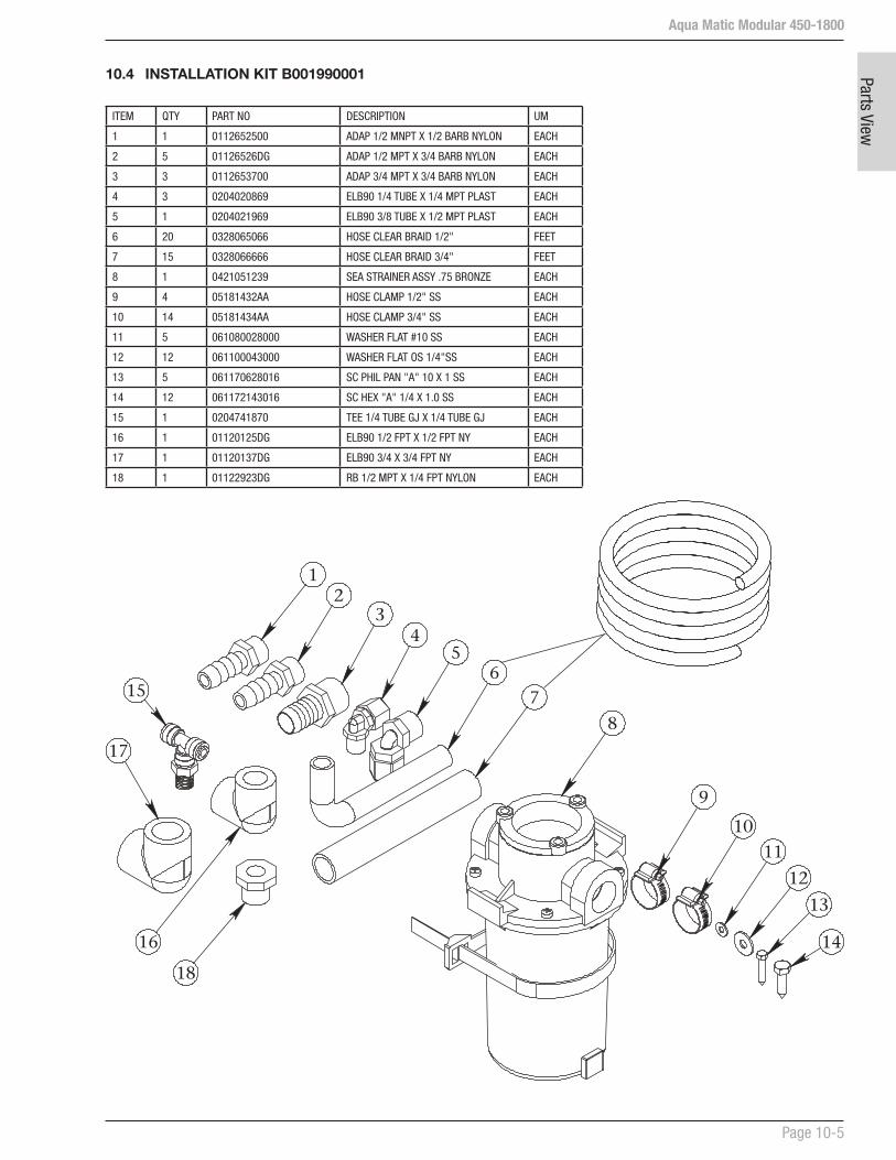
Aqua Matic Modular 450-1800
Page 10-5
Parts View
10.4 INSTALLATION KIT B001990001
ITEM QTY PART NO DESCRIPTION UM
1 1 0112652500 ADAP 1/2 MNPT X 1/2 BARB NYLON EACH
2 5 01126526DG ADAP 1/2 MPT X 3/4 BARB NYLON EACH
3 3 0112653700 ADAP 3/4 MPT X 3/4 BARB NYLON EACH
4 3 0204020869 ELB90 1/4 TUBE X 1/4 MPT PLAST EACH
5 1 0204021969 ELB90 3/8 TUBE X 1/2 MPT PLAST EACH
6 20 0328065066 HOSE CLEAR BRAID 1/2" FEET
7 15 0328066666 HOSE CLEAR BRAID 3/4" FEET
8 1 0421051239 SEA STRAINER ASSY .75 BRONZE EACH
9 4 05181432AA HOSE CLAMP 1/2" SS EACH
10 14 05181434AA HOSE CLAMP 3/4" SS EACH
11 5 061080028000 WASHER FLAT #10 SS EACH
12 12 061100043000 WASHER FLAT OS 1/4"SS EACH
13 5 061170628016 SC PHIL PAN "A" 10 X 1 SS EACH
14 12 061172143016 SC HEX "A" 1/4 X 1.0 SS EACH
15 1 0204741870 TEE 1/4 TUBE GJ X 1/4 TUBE GJ EACH
16 1 01120125DG ELB90 1/2 FPT X 1/2 FPT NY EACH
17 1 01120137DG ELB90 3/4 X 3/4 FPT NY EACH
18 1 01122923DG RB 1/2 MPT X 1/4 FPT NYLON EACH
23
45
7
8
9
1011
12
13
14
6
1
15
16
17
18

Aqua Matic Modular 450-1800
Page 10-6
Parts
Vie
w
10.5 MAJOR PARTS
1. SEA STRAINER ASSY 3/4-B B006080002
ITEM PART NUMBER DESCRIPTION QTY U/M
1 B006080002 SEA STRAINER ASSY 3/4-B (INCLUDES P/N 2-7) 1
2 0101073783 ELB90 .75 MNPT X .75 BARB PVC 2 EACH
3 05181434AA HOSE CLAMP 3/4” SS 4 EACH
4 0421051239 SEA STRAINER-3/4 BRONZE 1 EACH
5 0421051239-1 SIGHT GLASS 1 EACH
6 0421051239-7 BASKET MONEL 1 EACH
7 0421051239-2 O-RING, LID SEA STRAINER 1 EACH
5
7
6
2
3
4
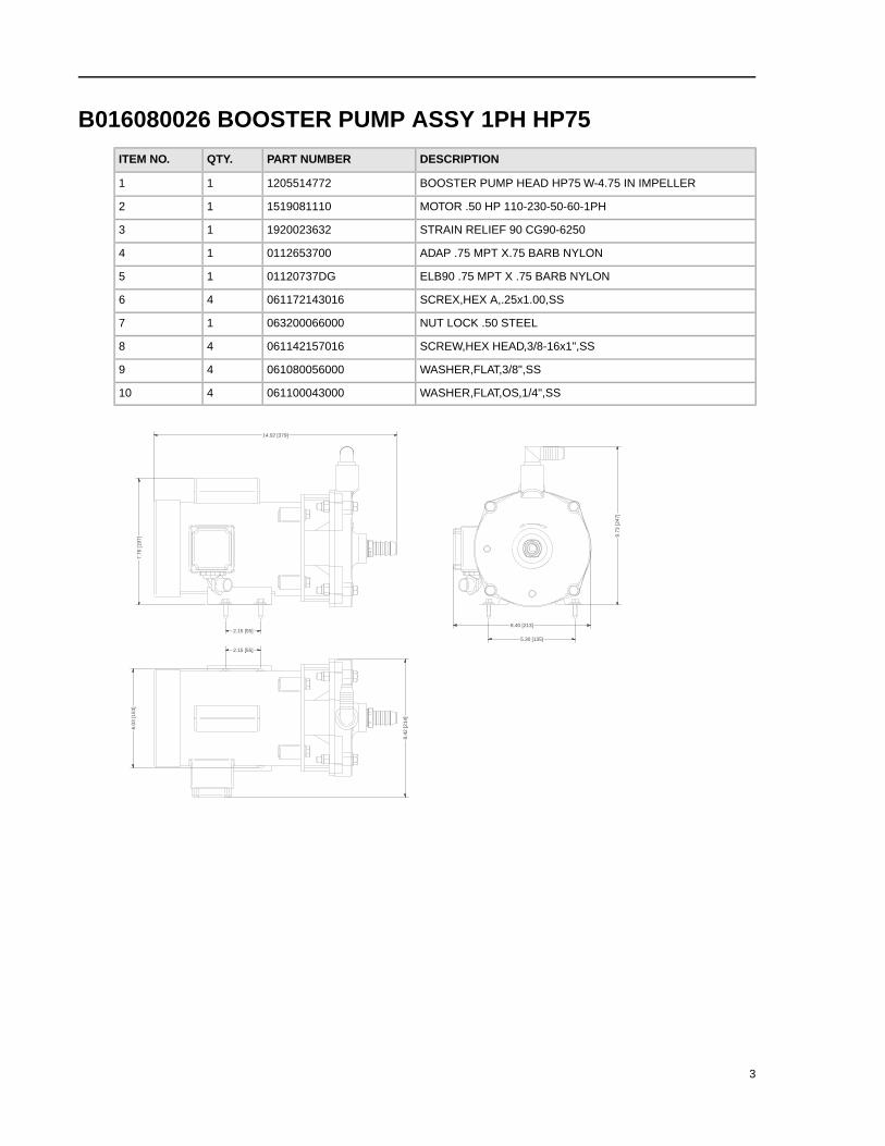
B016080026 BOOSTER PUMP ASSY 1PH HP75
DESCRIPTIONPART NUMBERQTY.ITEM NO.
BOOSTER PUMP HEAD HP75 W-4.75 IN IMPELLER120551477211
MOTOR .50 HP 110-230-50-60-1PH151908111012
STRAIN RELIEF 90 CG90-6250192002363213
ADAP .75 MPT X.75 BARB NYLON011265370014
ELB90 .75 MPT X .75 BARB NYLON01120737DG15
SCREX,HEX A,.25x1.00,SS06117214301646
NUT LOCK .50 STEEL06320006600017
SCREW,HEX HEAD,3/8-16x1",SS06114215701648
WASHER,FLAT,3/8",SS06108005600049
WASHER,FLAT,OS,1/4",SS061100043000410
9.73
[247
]
8.40 [213]
14.92 [379]
7.76
[197
]
5.30 [135]
2.15 [55]
2.15 [55]
6.03
[153
]
8.42
[214
]
3

7
3 6
10
9
8
1
4
5
2
RECOMMENDED SPARES:
DESCRIPTIONPART NUMBERQTY.
SEAL/SEAT BOOSTER PMP HP75 AB/SS26251301721
GASKET/ORING HP75 PP1205514772-11
IMPELLER 5" HP75 CPVC80290203500721
B016080026 BOOSTER PUMP ASSY 1PH HP754

B016080027 BOOSTER PUMP ASSY 3PH HP75
DESCRIPTIONPART NUMBERQTY.ITEM NO.
BRACKET,MTG,PUMP,BOOSTER1221514722-311
BOOSTER PUMP HEAD HP75 W-4.75 IN IMPELLER120551477212
MOTOR .50 HP 208-230-460-50-60152018111013
STRAIN RELIEF 90 CG90-6250192002363214
ADAP .75 MPT X.75 BARB NYLON011265370015
ELB90 .75 MPT X .75 BARB NYLON01120737DG16
SCREX,HEX A,.25x1.00,SS06117214301647
NUT LOCK .50 STEEL06320006600018
SCREW,HEX HEAD,3/8-16x1-1/4",SS06114215702049
WASHER,FLAT,3/8",SS061080056000410
WASHER,FLAT,OS,1/4",SS061100043000411
10.4
2 [2
65]
7.90 [201]
14.92 [379]
4.63 [118]3.63 [92]
3.26 [83]
4.94
[125
]
7.92
[201
]
3
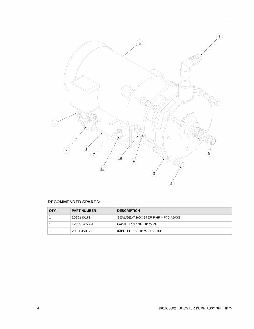
8
47
11
109
2
5
6
3
1
2
RECOMMENDED SPARES:
DESCRIPTIONPART NUMBERQTY.
SEAL/SEAT BOOSTER PMP HP75 AB/SS26251301721
GASKET/ORING HP75 PP1205514772-11
IMPELLER 5" HP75 CPVC80290203500721
B016080027 BOOSTER PUMP ASSY 3PH HP754

Aqua Matic Modular 450-1800
Page 10-10
Parts
Vie
w 5. MEDIA FILTER ASSY -4 HS/AW/UW B071080002
TEM PART NUMBER DESCRIPTION QTY U/M
1 0708040468-1 MEDIA FILTER HOUSING 818 ALMOND 1 EA
2 20200404010 BRACKET ""L"" MOUNTING FEET 4 EA
3 20200325000 SKID MEDIA FILTER AS>7/97 1 EA
4 061100043000 WASHER FLAT OS 1/4"SS 16 EA
5 061060045000 NUT HEX 1/4-20 W/INSERT SS 8 EA
6 05180851CC GAUGE BRACKET CBM SS 2 EA
7 0204010869 ELB90 1/4 TUBE X 1/4 FPT PLAST 2 EA
8 061142145012 BOLT HEX 1/4-20 X 3/4 SS 4 EA
9 061161845012 SC ALLEN FLAT 1/4-20 X 3/4 SS 4 EA
10 0708040400-1 MEDIA FILTER TOP 1 EA
11 0708040400-2 MEDIA FILTER RISER 1 EA
12 4643020255 MEDIA SAND A1000 (100LB BAG) 25 LB.
13 4643070155 MEDIA GARNET 8-12 50# BAG 17 LB.
14 2614017300 O-RING 334 MEDIA LID 97 1 EA
15 2614013001 O-RING 209 1 EA
16 2614017400 O-RING 117 MEDIA TOP INLET 1 EA
17 0708040400-3 PLUG MEDIA FILTER TOP 1 EA
18 B075000001 MULTI MEDIA FILTER PLUMBING 1 EA
19 10181522CC GAUGE -30/0/70 CBM.NPT 2 EA
Refer to illustration on next page
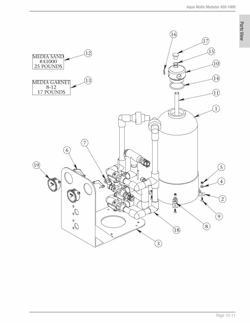
Aqua Matic Modular 450-1800
Page 10-11
Parts View
3
18
4
5
9
2
1
11
14
10
15
1716
19
6
7
8
12
13MEDIA GARNET8-12
17 POUNDS
MEDIA SAND#A1000
25 POUNDS
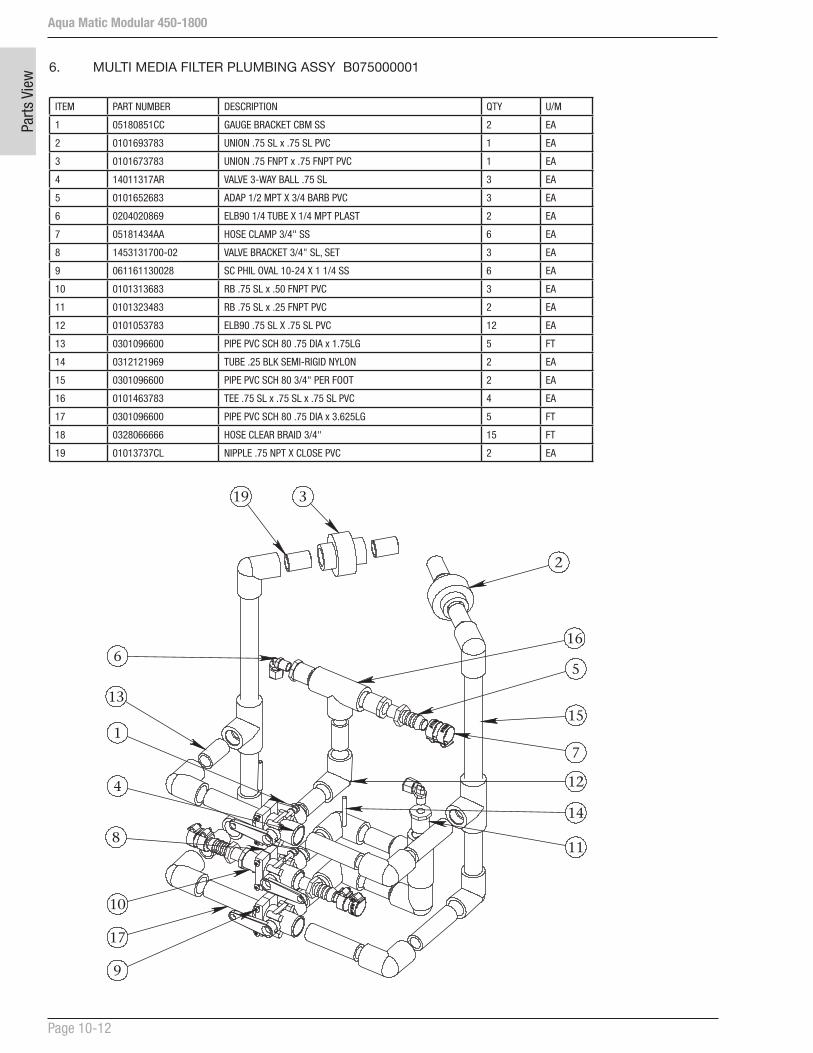
Aqua Matic Modular 450-1800
Page 10-12
Parts
Vie
w
6. MULTI MEDIA FILTER PLUMBING ASSY B075000001
ITEM PART NUMBER DESCRIPTION QTY U/M
1 05180851CC GAUGE BRACKET CBM SS 2 EA
2 0101693783 UNION .75 SL x .75 SL PVC 1 EA
3 0101673783 UNION .75 FNPT x .75 FNPT PVC 1 EA
4 14011317AR VALVE 3-WAY BALL .75 SL 3 EA
5 0101652683 ADAP 1/2 MPT X 3/4 BARB PVC 3 EA
6 0204020869 ELB90 1/4 TUBE X 1/4 MPT PLAST 2 EA
7 05181434AA HOSE CLAMP 3/4" SS 6 EA
8 1453131700-02 VALVE BRACKET 3/4" SL, SET 3 EA
9 061161130028 SC PHIL OVAL 10-24 X 1 1/4 SS 6 EA
10 0101313683 RB .75 SL x .50 FNPT PVC 3 EA
11 0101323483 RB .75 SL x .25 FNPT PVC 2 EA
12 0101053783 ELB90 .75 SL X .75 SL PVC 12 EA
13 0301096600 PIPE PVC SCH 80 .75 DIA x 1.75LG 5 FT
14 0312121969 TUBE .25 BLK SEMI-RIGID NYLON 2 EA
15 0301096600 PIPE PVC SCH 80 3/4" PER FOOT 2 EA
16 0101463783 TEE .75 SL x .75 SL x .75 SL PVC 4 EA
17 0301096600 PIPE PVC SCH 80 .75 DIA x 3.625LG 5 FT
18 0328066666 HOSE CLEAR BRAID 3/4" 15 FT
19 01013737CL NIPPLE .75 NPT X CLOSE PVC 2 EA
19 3
2
16
15
7
12
14
11
5
9
17
10
8
1
13
4
6

Aqua Matic Modular 450-1800
Page 10-13
Parts View
7. PLANKTON FILTER ASSY-SINGLE B008800001
ITEM PART NUMBER DESCRIPTION QTY U/M
1 B008800001 PLANKTON FILTER ASSY-AW SINGLE (INCLUDES P/N 2-7) 1 EA
2 05181434AA HOSE CLAMP 3/4” SS 4 EA
3 0805823578 ELEMENT PLANKTON 1 EA
4 0101073783 ELB90 .75 MNPT X .75 BARB PVC 2 EA
5 20200402102 SINGLE FILTER BRACKET 1 EA
6 0713020473 FILTER HOUSING-LID .75 X 10 ASM 1 EA
7 2614010473 O-RING 237 BLUE HOUSING 1 EA
5
3
6
2
6
4
7

Aqua Matic Modular 450-1800
Page 10-14
Parts
Vie
w 8. PLANKTON FILTER ASSY-DOUBLE B008800002
ITEM PART NUMBER DESCRIPTION QTY U/M
1 0713020473 FILTER HOUSING-LID .75 X 10 ASM 2 EA
2 01013737CL NIPPLE .75 NPT X CLOSE PVC 4 EA
3 0101423783 TEE .75 FNPT x .75 FNPT x .75 FNPT PVC 2 EA
4 0101653783 ADAP 3/4 MPT X 3/4 BARB PVC 3 EA
5 0101013783 ELB90 .75 FPT X .75 FPT PVC 2 EA
6 0101073783 ELB90 .75 MNPT X .75 BARB PVC 3 EA
7 0328066666 HOSE CLEAR BRAID 3/4" 2 EA
8 05181434AA HOSE CLAMP 3/4" SS 12 EA
9 0805823578 ELEMENT PLANKTON 2 EA
10 20200402102 SINGLE FILTER BRACKET 2 EA
11 061172143016 SC HEX "A" 1/4 X 1.0 SS 8 EA
12 061100043000 WASHER FLAT OS 1/4"SS 8 EA
13 061170628016 SC PHIL PAN "A" 10 X 1 SS 8 EA
14 065080028000 WASHER FLAT #10 NYLON 8 EA
1
2
3
6
5
4
7
8
9
10
1314
11
12

Aqua Matic Modular 450-1800
Page 10-15
Parts View
PREFILTRATION CARTRIDGE FILTER ELEMENT WARNING:
Do not use third party Prefiltration Elements (Plankton Filter Elements, Prefilter Elements, Commercial Prefilter Elements, or Oil/Water Separator Elements). Use only Sea Recovery supplied Prefiltration Elements. Third party prefiltration elements on the market do not properly fit into the Sea Recovery Filter Housings, the seams fall apart, and they will allow by-pass resulting in EXTENSIVE AND EXPENSIVE DAMAGE TO THE HIGH PRESSURE PUMP AS WELL AS PREMATURE FOULING OF THE R.O. MEMBRANE ELEMENT.
Damage caused to the Sea Recovery High Pressure Pump, R.O. Membrane Element, or any other component from the use of third party, non Sea Recovery supplied, filter elements is the responsibility and liability of the operator and is not covered by the Sea Recovery Warranty.
FILTER ELEMENT CAUTION:
Do not use “string wound” or “fiber” type prefilter elements. These type of elements are designed for the Photographic Film Developing industry. When used in sea water they will plug up rapidly in 1/10th or less the time causing frequent shut down of the system and very frequent changing resulting in very high cost of maintenance.

Aqua Matic Modular 450-1800
Page 10-16
Parts
Vie
w 9. PREFILTER DUAL AQM II B108140001
ITEM NO. PART NUMBER DESCRIPTION QTY.
1 B108140001 PREFILTER DUAL AQM II (INCLUDES P/N 2-8) 1
2 0801130257 ELEMENT PREFILTER 10-25 1
3 0801060157 ELEMENT PREFILTER 10-05 1
4 20200402101 DUAL BRACKET PREFILTER, CHRCL, PLNKTN 1
5 0112072600 ELB90 1/2 MPT X 3/4 BARB NYLON 2
6 05181434AA HOSE CLAMP 3/4" SS 4
7 2614010473 O-RING 237 BLUE HOUSING 2
8 0713020873 FILTER HOUSING 1/2" X 10 2
4
6
7
8
3
2
5

Aqua Matic Modular 450-1800
Page 10-17
Parts View
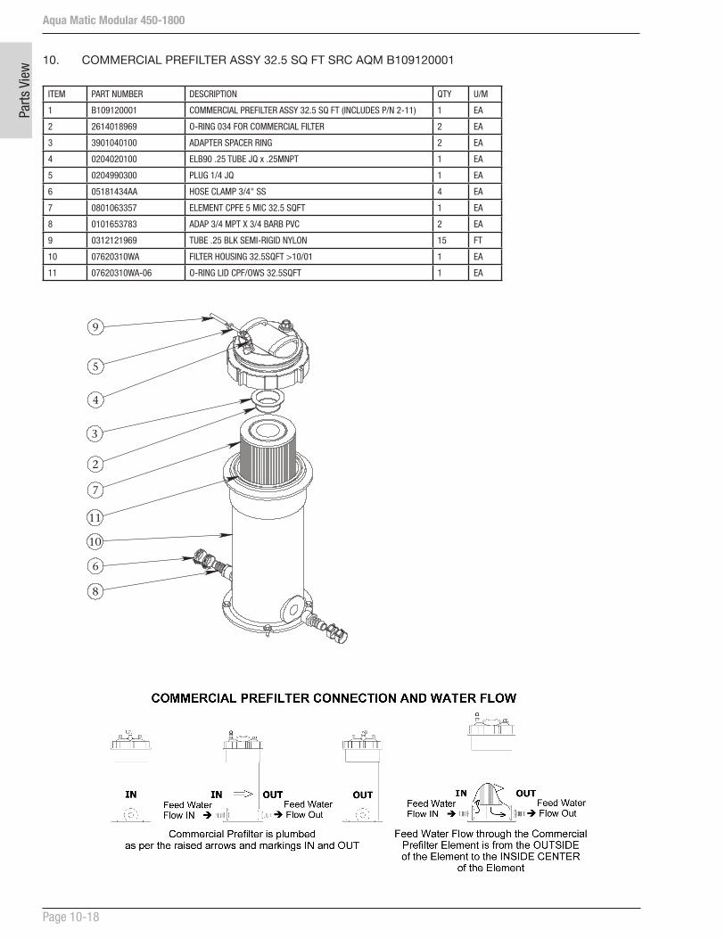
Aqua Matic Modular 450-1800
Page 10-18
Parts
Vie
w 10. COMMERCIAL PREFILTER ASSY 32.5 SQ FT SRC AQM B109120001
ITEM PART NUMBER DESCRIPTION QTY U/M
1 B109120001 COMMERCIAL PREFILTER ASSY 32.5 SQ FT (INCLUDES P/N 2-11) 1 EA
2 2614018969 O-RING 034 FOR COMMERCIAL FILTER 2 EA
3 3901040100 ADAPTER SPACER RING 2 EA
4 0204020100 ELB90 .25 TUBE JQ x .25MNPT 1 EA
5 0204990300 PLUG 1/4 JQ 1 EA
6 05181434AA HOSE CLAMP 3/4" SS 4 EA
7 0801063357 ELEMENT CPFE 5 MIC 32.5 SQFT 1 EA
8 0101653783 ADAP 3/4 MPT X 3/4 BARB PVC 2 EA
9 0312121969 TUBE .25 BLK SEMI-RIGID NYLON 15 FT
10 07620310WA FILTER HOUSING 32.5SQFT >10/01 1 EA
11 07620310WA-06 O-RING LID CPF/OWS 32.5SQFT 1 EA
9
5
4
7
8
6
3
2
11
10
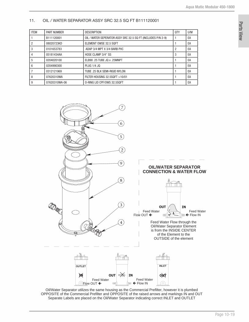
Aqua Matic Modular 450-1800
Page 10-19
Parts View
11. OIL / WATER SEPARATOR ASSY SRC 32.5 SQ FT B111120001
ITEM PART NUMBER DESCRIPTION QTY U/M
1 B111120001 OIL / WATER SEPERATOR ASSY SRC 32.5 SQ FT (INCLUDES P/N 2-9) 1 EA
2 08020723KD ELEMENT OWSE 32.5 SQFT 1 EA
3 0101653783 ADAP 3/4 MPT X 3/4 BARB PVC 2 EA
4 05181434AA HOSE CLAMP 3/4" SS 3 EA
5 0204020100 ELB90 .25 TUBE JQ x .25MNPT 1 EA
6 0204990300 PLUG 1/4 JQ 1 EA
7 0312121969 TUBE .25 BLK SEMI-RIGID NYLON 1 EA
8 07620310WA FILTER HOUSING 32.5SQFT >10/01 1 EA
9 07620310WA-06 O-RING LID CPF/OWS 32.5SQFT 1 EA
Feed WaterFlow OUT
INOUTIN OUT Feed Water Flow IN
Oil/Water Separator utilizes the same housing as the Commercial Prefilter, however it is plumbedOPPOSITE of the Commercial Prefilter and OPPOSITE of the raised arrows and markings IN and OUT
Separate Labels are placed on the Oil/Water Separator indicating correct INLET and OUTLET
Feed WaterFlow OUT
INOUT Feed Water Flow IN
Feed Water Flow through theOil/Water Separator Elementis from the INSIDE CENTER
of the Element to theOUTSIDE of the element
OIL/WATER SEPARATORCONNECTION & WATER FLOW
INLETOUTLET
5
7
2
3
8
4
9
6
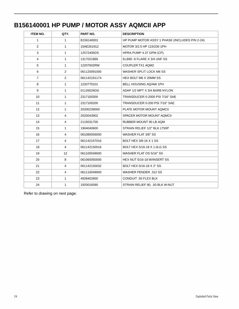
B156140001 HP PUMP / MOTOR ASSY AQMCII APPDESCRIPTIONPART NO.QTY.ITEM NO.
HP PUMP MOTOR ASSY 1 PHASE (INCLUDES P/N 2-24)B15614000111
MOTOR 3/2.5 HP 115/230 1PH15AE26191212
HPRA PUMP 4.37 GPM (CP)12572405DS13
ELB90 -6 FLARE X 3/4 UNF SS131702186914
COUPLER TX1 AQM212207602RW15
WASHER SPLIT LOCK M6 SS06112009100026
HEX BOLT M6 X 20MM SS06114219117427
BELL HOUSING AQ/AW 1PH122077010118
ADAP 1/2 MPT X 3/4 BARB NYLON01126526DG19
TRANSDUCER 0-2000 PSI 7/16" SAE2317100300110
TRANSDUCER 0-200 PSI 7/16" SAE2317100200111
PLATE MOTOR MOUNT AQMCII20200239000112
SPACER MOTOR MOUNT AQMCII2020043902413
RUBBER MOUNT 90 LB AQM2115031700414
STRAIN RELIEF 1/2" BLK LT50P1904040600115
WASHER FLAT 3/8" SS061080056000416
BOLT HEX 3/8-16 X 1 SS061142157016417
BOLT HEX 5/16-18 X 1.0LG SS061142150016418
WASHER FLAT OS 5/16" SS0611000490001219
HEX NUT 5/16-18 W/INSERT SS061060050000820
BOLT HEX 5/16-18 X 2" SS061142150032421
WASHER FENDER .312 SS061110049000422
CONDUIT .50 FLEX BLK4928402800123
STRAIN RELIEF 90, .50 BLK W-NUT1920016590124
Refer to drawing on next page.
Exploded Parts View24

2
8
11
5
10
7
9
3164
15
6
14
13
12
17
22
21
20
19
19
18
24
23
25

B156140002 HP PUMP / MOTOR ASSY AQMCII APP 3PHDESCRIPTIONPART NO.QTY.ITEM NO.
HP PUMP / MOTOR ASSY AQMC II 3PH (INCLUDES P/N 2-24)B15614000211
MOTOR 3/2.5 HP 3 PH AQM 50/615AF27191012
HPRA PUMP 4.37 GPM (CP)12572405DS13
ELB90 -6 FLARE X 3/4 UNF SS131702186914
COUPLER TX1 AQM212207602RW15
WASHER SPLIT LOCK M6 SS06112009100026
HEX BOLT M6 X 20MM SS06114219117427
BELL HOUSING AQ/AW 3PH122077010318
ADAP 1/2 MPT X 3/4 BARB NYLON01126526DG19
TRANSDUCER 0-2000 PSI 7/16" SAE2317100300110
TRANSDUCER 0-200 PSI 7/16" SAE2317100200111
PLATE MOTOR MOUNT AQMCII20200239000112
SPACER MOTOR MOUNT AQMCII2020043902413
RUBBER MOUNT 90 LB AQM2115031700414
STRAIN RELIEF 1/2" BLK LT50P1904040600115
WASHER FLAT 3/8" SS061080056000416
BOLT HEX 3/8-16 X 1 SS061142157016417
WASHER FLAT OS 5/16" SS0611000490001218
HEX NUT 5/16-18 W/INSERT SS061060050000819
STRAIN RELIEF 90, .50 BLK W-NUT1920016590120
CONDUIT .50 FLEX BLK4928402800121
BOLT HEX 5/16-18 X 1.0LG SS061142150016422
BOLT HEX 5/16-18 X 2" SS061142150032423
WASHER FENDER .312 SS061110049000424
Refer to drawing on next page.
Exploded Parts View26

2
8
11
5
10
7
9
3
6
415
12
13
14
19
18
23
24
21
20
1716
22
27
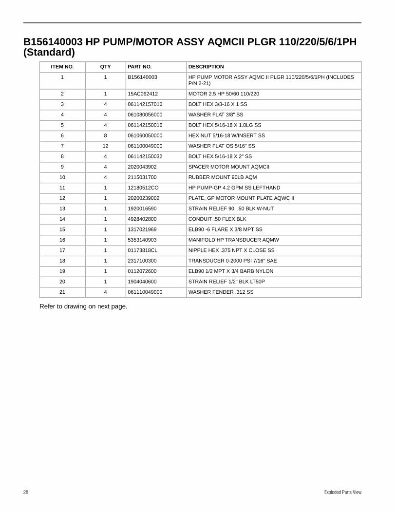
B156140003 HP PUMP/MOTOR ASSY AQMCII PLGR 110/220/5/6/1PH(Standard)
DESCRIPTIONPART NO.QTYITEM NO.
HP PUMP MOTOR ASSY AQMC II PLGR 110/220/5/6/1PH (INCLUDESP/N 2-21)
B15614000311
MOTOR 2.5 HP 50/60 110/22015AC06241212
BOLT HEX 3/8-16 X 1 SS06114215701643
WASHER FLAT 3/8" SS06108005600044
BOLT HEX 5/16-18 X 1.0LG SS06114215001645
HEX NUT 5/16-18 W/INSERT SS06106005000086
WASHER FLAT OS 5/16" SS061100049000127
BOLT HEX 5/16-18 X 2" SS06114215003248
SPACER MOTOR MOUNT AQMCII202004390249
RUBBER MOUNT 90LB AQM2115031700410
HP PUMP-GP 4.2 GPM SS LEFTHAND12180512CO111
PLATE, GP MOTOR MOUNT PLATE AQWC II20200239002112
STRAIN RELIEF 90, .50 BLK W-NUT1920016590113
CONDUIT .50 FLEX BLK4928402800114
ELB90 -6 FLARE X 3/8 MPT SS1317021969115
MANIFOLD HP TRANSDUCER AQMW5353140903116
NIPPLE HEX .375 NPT X CLOSE SS01173818CL117
TRANSDUCER 0-2000 PSI 7/16" SAE2317100300118
ELB90 1/2 MPT X 3/4 BARB NYLON0112072600119
STRAIN RELIEF 1/2" BLK LT50P1904040600120
WASHER FENDER .312 SS061110049000421
Refer to drawing on next page.
Exploded Parts View28
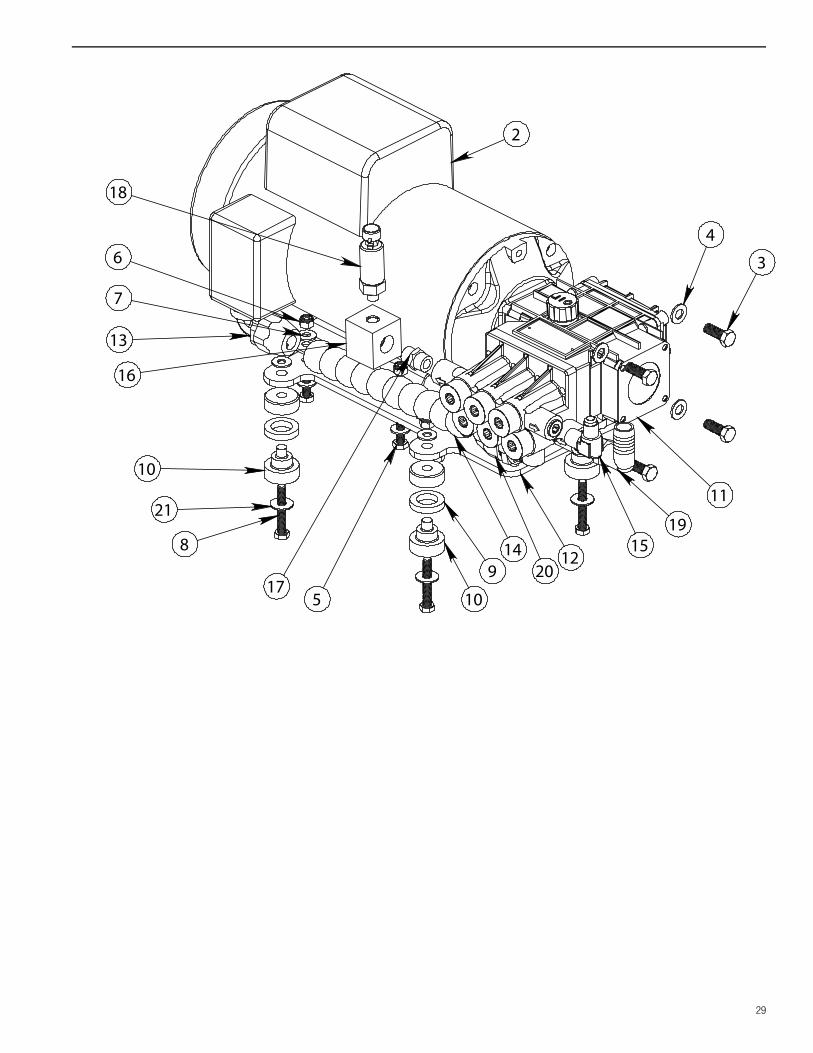
2
4
3
1915
11
129
10
8 14
17
16
10
13
5
6
18
7
21
20
29

B156140004 HP PUMP/MOTOR ASSY AQMCII PLGR 220/440/60/3PHDESCRIPTIONPART NO.QTYITEM NO.
HP PUMP MOTOR ASSY AQMC II PLGR 220/440/60/3PH (INCLUDESP/N 2-21)
B15614000411
BOLT HEX 3/8-16 X 1 SS06114215701642
WASHER FLAT 3/8" SS06108005600043
BOLT HEX 5/16-18 X 1.0LG SS06114215001644
HEX NUT 5/16-18 W/INSERT SS06106005000085
WASHER FLAT OS 5/16" SS061100049000126
BOLT HEX 5/16-18 X 2" SS06114215003247
SPACER MOTOR MOUNT AQMCII202004390248
RUBBER MOUNT 90LB AQM211503170049
HP PUMP-GP 4.2 GPM SS LEFTHAND12180512CO110
PLATE, GP MOTOR MOUNT PLATE AQWC II20200239002111
STRAIN RELIEF 90, .50 BLK W-NUT1920016590112
CONDUIT .50 FLEX BLK4928402800113
ELB90 -6 FLARE X 3/8 MPT SS1317021969114
MANIFOLD HP TRANSDUCER AQMW5353140903115
NIPPLE HEX .375 NPT X CLOSE SS01173818CL116
TRANSDUCER 0-2000 PSI 7/16" SAE2317100300117
ELB90 1/2 MPT X 3/4 BARB NYLON0112072600118
STRAIN RELIEF 1/2" BLK LT50P1904040600119
WASHER FENDER .312 SS061110049000420
MOTOR 3 HP 220/60-440/60 3PH15AE231012121
Refer to drawing on next page.
Exploded Parts View30
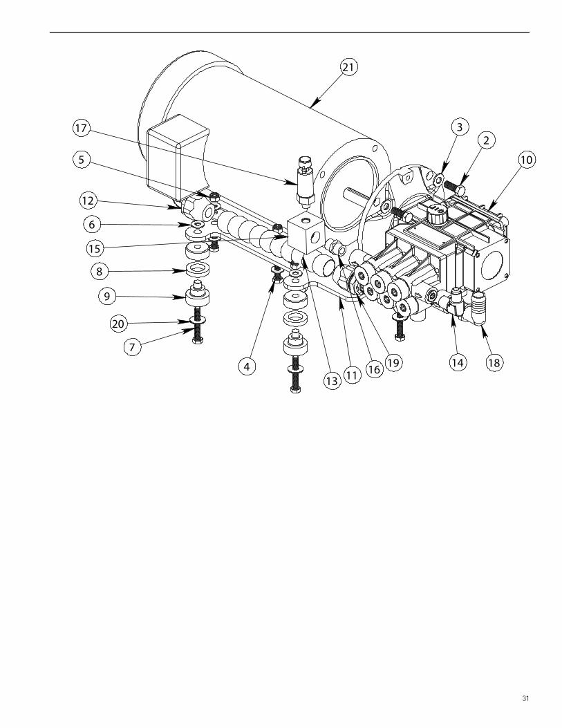
21
32
1814
10
11
7
16
15
9
12
4
5
17
20
19
8
6
13
31

B156140006 HP PUMP/MOTOR PLGR AQMCII 110/220/6/1 SMALL 60HZ
DESCRIPTIONPART NO.QTYITEM NO.
HP PUMP MOTOR PLGR AQMC II 110/220/6/1SMALL 60 HZ(INCLUDES P/N 2-21)
B15614000311
MOTOR 2.5 HP 50/60 110/22015AC06241212
BOLT HEX 3/8-16 X 1 SS06114215701643
WASHER FLAT 3/8" SS06108005600044
BOLT HEX 5/16-18 X 1.0LG SS06108005600045
HEX NUT 5/16-18 W/INSERT SS06106005000086
WASHER FLAT OS 5/16" SS061100049000127
BOLT HEX 5/16-18 X 2" SS06114215003248
SPACER MOTOR MOUNT AQMCII202004390249
RUBBER MOUNT 90LB AQM2115031700410
PLATE, GP MOTOR MOUNT PLATE AQWC II20200239002111
STRAIN RELIEF 90, .50 BLK W-NUT1920016590112
CONDUIT .50 FLEX BLK4928402800113
ELB90 -6 FLARE X 3/8 MPT SS1317021969114
MANIFOLD HP TRANSDUCER AQMW5353140903115
NIPPLE HEX .375 NPT X CLOSE SS01173818CL116
TRANSDUCER 0-2000 PSI 7/16" SAE2317100300117
ELB90 1/2 MPT X 3/4 BARB NYLON0112072600118
STRAIN RELIEF 1/2" BLK LT50P1904040600119
WASHER FENDER .312 SS061110049000420
HP PUMP-GP 3.0 GPM LEFTHAND12180511CO121
Refer to drawing on next page.
Exploded Parts View32

2
43
1814
21
119
10
8 13
16
15
10
12
5
6
17
7
20
19
33

Aqua Matic Modular 450-1800
Page 10-25
Parts View
This page is intentionally left blank.

Aqua Matic Modular 450-1800
Page 10-26
Parts
Vie
w
17. HP PUMP ASSY-12180513CO (Standard)
ITEM NO. PART NUMBER DESCRIPTION QTY
1-52 12180511CO Pump HP 3.0 GPM SS Left (complete high pressure pump) 1
12180512CO Pump HP 4.2 GPM SS Left (complete high pressure pump)
1-29 12180511CO-CCAL Crank Case Stuffed HP 3.0 GPM SS Left 1
12180512CO-CCAL Crank Case Stuffed HP 4.2 GPM SS Left
30-52 12180511CO-WE Manifold Stuffed HP 3.0 GPM SS 1
12180512CO-WE Manifold Stuffed HP 4.2 GPM SS
1 12180510CO-01 Crankcase 1
2 12180510CO-02 Connecting Rod 3
3 12180511CO-03 Crankshaft 5/8” Hollow 3.0 GPM 1
12180512CO-03 Crankshaft 5/8” Hollow 4.2 GPM
4 12180510CO-04 Bearing 2
5 12180510CO-05 Oil Seal, Crankshaft 1
6 12180510CO-06 Retainer, Oil Seal 1
7 12180510CO-07 O-ring, Oil Seal Retainer/Side Cover 2
8 12180510CO-08 Flange, NEMA 56C Face 1
9 12180510CO-09 Screw SHCS 18mm Long 4
10 12180510CO-10 Oil Cap Vented 1
11 12180510CO-11 Rear Cover 1
12 12180510CO-12 Screw SHCS 16mm Long 8
13 12180510CO-13 Sight Glass 1
14 12180510CO-14 O-ring, Rear Cover 1
15 12180510CO-15 Bushing 1
16 12180510CO-16 Washer 1
17 12180510CO-17 Screw HHCS 20mm long 1
18 12180510CO-18 Side Cover 1
19 12180510CO-19 Side Plate 1
20 12180510CO-20 Oil Drain Plug 1
21 12180510CO-21 Oil Seal Plunger 3
22 12180510CO-22 Wrist Pin 3
23 12180510CO-23 Plunger Rod 3
24 12180510CO-24 Slinger 3
25 12180510CO-25 Anti-Extrusion Ring 3
26 12180510CO-26 O-ring Plunger 3
27 12180510CO-27 Plunger 18mm 3
28 12180510CO-28 Washer, Plunger Rod 3
29 12180510CO-29 Nut, Plunger Rod 3
30 12180510CO-30 Seal Retainer 3
31 12180510CO-31 Low Pressure Seal 3
32 12180510CO-32 O-ring Seal Case 3
33 12180510CO-33 Seal case 3
34 12180510CO-34 Square Ring, High Pressure Seal 3
35 12180510CO-35 Glide Ring, High Pressure Seal 3
36 12180510CO-36 Manifold 1
37 12180510CO-37 1/4 NPT Plug 3
38 12180510CO-38 3/8 NPT Plug 1
39 12180510CO-39 1/2 NPT Plug 1
40 12180510CO-40 O-ring Valve Spacer 6
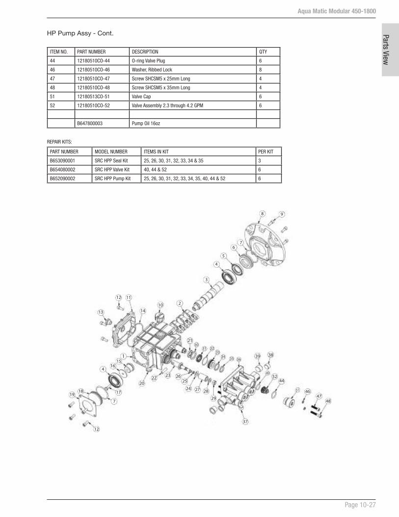
Aqua Matic Modular 450-1800
Page 10-27
Parts View
1
2
3
4
5
6
8 9
1112
13 14
1516
171819
21
2022
23
24
26
27 28
29
3031 32
3334 35 36
37
3839
40
4647
48
51
4
12
7
7
5244
10
25
ITEM NO. PART NUMBER DESCRIPTION QTY
44 12180510CO-44 O-ring Valve Plug 6
46 12180510CO-46 Washer, Ribbed Lock 8
47 12180510CO-47 Screw SHCSM5 x 25mm Long 4
48 12180510CO-48 Screw SHCSM5 x 35mm Long 4
51 12180513CO-51 Valve Cap 6
52 12180510CO-52 Valve Assembly 2.3 through 4.2 GPM 6
B647800003 Pump Oil 16oz
REPAIR KITS:
PART NUMBER MODEL NUMBER ITEMS IN KIT PER KIT
B653090001 SRC HPP Seal Kit 25, 26, 30, 31, 32, 33, 34 & 35 3
B654080002 SRC HPP Valve Kit 40, 44 & 52 6
B652090002 SRC HPP Pump Kit 25, 26, 30, 31, 32, 33, 34, 35, 40, 44 & 52 6
HP Pump Assy - Cont.

Aqua Matic Modular 450-1800
Page 10-28
Parts
Vie
w
18. HP HOSE ASSEMBLY
PART NUMBER DESCRIPTION QTY
2432160669 HOSE HP - 6P 1
1317481969 SWIVEL FITTING - 6 SSP 2

Aqua Matic Modular 450-1800
Page 10-29
Parts View
19. MEMBRANE RACK 450-1 - B198000032
ITEM NO. QTY. PART NUMBER DESCRIPTION
1 1 2408132500 VESSEL HIGH PRESSURE 450GPD
2 1 2724011233 MEMBRANE 450GPD W-SEAL
3 2 0520210600 RETAINER PORT MVA AW
4 4 2614014900 O-RING 230 BRINE 3" END PLUG
5 2 2614010100 O-RING 116 PRODUCT
6 1 0101370820 NIPPLE .25 NPT X 2.0 PVC
7 1 2453512400 END PLUG DUAL 3" AW
8 1 2453502401 END PLUG SINGLE 3 AW LONGER
9 6 061162345012 SC SOC CAP 1/4-20 X 3/4 SS
10 1 0204010869 ELB90 1/4 TUBE X 1/4 FNPT PLASTIC
11 1 0312121969 TUBE 1/4 BLACK
12 2 0117410800 NIPPLE HP MVA AW
13 4 2614017900 O-RING 115 INTERCONNECT AW
14 2 1317011769 ELB90 6 FLARE X .25 FPT SS
15 2 1317481969 SWIVEL FITTING 6 SS P
ITEM NO. QTY. PART NUMBER DESCRIPTION
16 2 20201030000 SEGMENT RING AW (SET)
17 2 2432160669 HOSE HP -6P
18 2 2632180426 DECOFELT .125 x 1.25 BLK
19 1 0204690100 REDUCER .375 x .25 JQ
20 1 2220010660 LABEL MEMBRANE SERIAL NO
21 1 2234011260 LABEL INLET (SRC BLUE)
22 1 2234011360 LABEL OUTLET (SRC BLUE)
23 2 061100043000 WASHER FLAT OS 1/4"SS
24 2 061142145012 BOLT HEX 1/4-20 X 3/4 SS
25 4 061161845012 SC ALLEN FLAT 1/4-20 X 3/4 SS
26 2 0520051800 MVA RACK AW SERIES
27 1 0204741800 UNION TEE 3/8 X 3/8 X 3/8 DIV
28 1 0204990200 PLUG .375 JQ
29 2 05202401GR BRACKET MVA U-CLAMP
9
16
3
74 5
2131214151728
27
19
11
10
6
25
26
23
1
29
8
24
(cont.)

Aqua Matic Modular 450-1800
Page 10-30
Parts
Vie
w
20. MEMBRANE RACK 700-1 - B198000033
ITEM NO. QTY. PART NUMBER DESCRIPTION
1 1 2408132500-01 VESSEL HIGH PRESSURE 700GPD
2 1 2724011333 MEMBRANE 700GPD W-SEAL
3 2 0520210600 RETAINER PORT MVA AW
4 4 2614014900 O-RING 230 BRINE 3" END PLUG
5 2 2614010100 O-RING 116 PRODUCT
6 1 0101370820 NIPPLE .25 NPT X 2.0 PVC
7 1 2453512400 END PLUG DUAL 3" AW
8 1 2453502401 END PLUG SINGLE 3 AW LONGER
9 6 061162345012 SC SOC CAP 1/4-20 X 3/4 SS
10 1 0204010869 ELB90 1/4 TUBE X 1/4 FNPT PLASTIC
11 1 0312121969 TUBE 1/4 BLACK
12 2 0117410800 NIPPLE HP MVA AW
13 4 2614017900 O-RING 115 INTERCONNECT AW
14 2 1317011769 ELB90 6 FLARE X .25 FPT SS
15 2 20201030000 SEGMENT RING AW (SET)
16 2 2632180426 DECOFELT .125 x 1.25 BLK
17 1 0204690100 REDUCER .375 x .25 JQ
18 1 2220010660 LABEL MEMBRANE SERIAL NO
19 1 2234011260 LABEL INLET (SRC BLUE)
20 1 2234011360 LABEL OUTLET (SRC BLUE)
21 2 061100043000 WASHER FLAT OS 1/4"SS
22 2 061142145012 BOLT HEX 1/4-20 X 3/4 SS
23 4 061161845012 SC ALLEN FLAT 1/4-20 X 3/4 SS
24 2 0520051800 MVA RACK AW SERIES
25 1 0204741800 UNION TEE 3/8 X 3/8 X 3/8 DIV
26 1 0204990200 PLUG .375 JQ
27 2 05202401GR BRACKET MVA U-CLAMP
9
15
37
4 5
213121426
25
17
11
10
6
23
24
21
1
27
8
22

Aqua Matic Modular 450-1800
Page 10-31
Parts View
21. MEMBRANE RACK 900-1 - B198000034
ITEM NO. QTY. PART NUMBER DESCRIPTION
1 1 2408132500-02 VESSEL HIGH PRESSURE 900GPD
2 1 2724011433 MEMBRANE 900GPD W-SEAL
3 2 0520210600 RETAINER PORT MVA AW
4 4 2614014900 O-RING 230 BRINE 3" END PLUG
5 2 2614010100 O-RING 116 PRODUCT
6 1 0101370820 NIPPLE .25 NPT X 2.0 PVC
7 1 2453512400 END PLUG DUAL 3" AW
8 1 2453502401 END PLUG SINGLE 3 AW LONGER
9 6 061162345012 SC SOC CAP 1/4-20 X 3/4 SS
10 1 0204010869 ELB90 1/4 TUBE X 1/4 FNPT PLASTIC
11 1 0312121969 TUBE 1/4 BLACK
12 2 0117410800 NIPPLE HP MVA AW
13 4 2614017900 O-RING 115 INTERCONNECT AW
14 2 1317011769 ELB90 6 FLARE X .25 FPT SS
15 2 20201030000 SEGMENT RING AW (SET)
16 2 2632180426 DECOFELT .125 x 1.25 BLK
17 1 0204690100 REDUCER .375 x .25 JQ
18 1 2220010660 LABEL MEMBRANE SERIAL NO
19 1 2234011260 LABEL INLET (SRC BLUE)
20 1 2234011360 LABEL OUTLET (SRC BLUE)
21 2 061100043000 WASHER FLAT OS 1/4"SS
22 2 061142145012 BOLT HEX 1/4-20 X 3/4 SS
23 4 061161845012 SC ALLEN FLAT 1/4-20 X 3/4 SS
24 2 0520051800 MVA RACK AW SERIES
25 1 0204741800 UNION TEE 3/8 X 3/8 X 3/8 DIV
26 1 0204990200 PLUG .375 JQ
27 2 05202401GR BRACKET MVA U-CLAMP
9
15
37
4 5
213121426
25
17
11
10
6
23
24
21
1
27
8
22
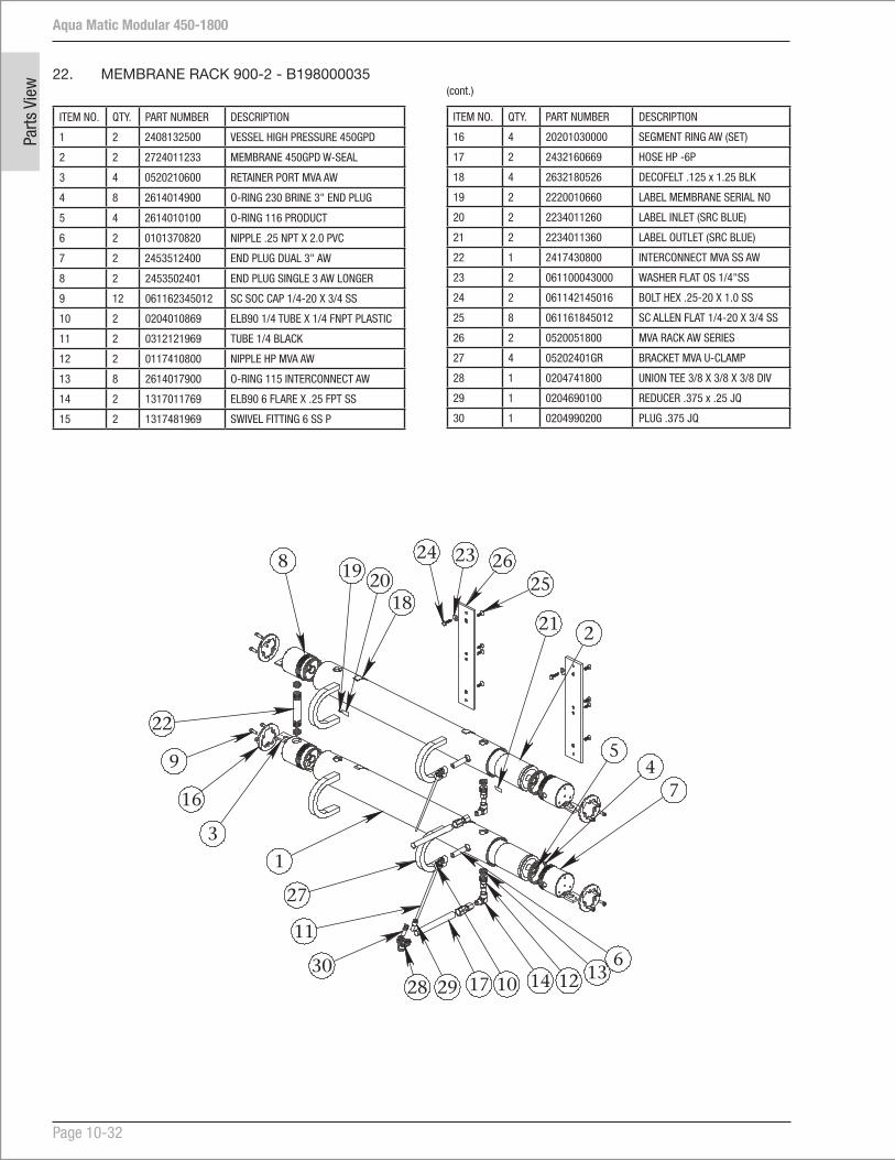
Aqua Matic Modular 450-1800
Page 10-32
Parts
Vie
w 22. MEMBRANE RACK 900-2 - B198000035
ITEM NO. QTY. PART NUMBER DESCRIPTION
1 2 2408132500 VESSEL HIGH PRESSURE 450GPD
2 2 2724011233 MEMBRANE 450GPD W-SEAL
3 4 0520210600 RETAINER PORT MVA AW
4 8 2614014900 O-RING 230 BRINE 3" END PLUG
5 4 2614010100 O-RING 116 PRODUCT
6 2 0101370820 NIPPLE .25 NPT X 2.0 PVC
7 2 2453512400 END PLUG DUAL 3" AW
8 2 2453502401 END PLUG SINGLE 3 AW LONGER
9 12 061162345012 SC SOC CAP 1/4-20 X 3/4 SS
10 2 0204010869 ELB90 1/4 TUBE X 1/4 FNPT PLASTIC
11 2 0312121969 TUBE 1/4 BLACK
12 2 0117410800 NIPPLE HP MVA AW
13 8 2614017900 O-RING 115 INTERCONNECT AW
14 2 1317011769 ELB90 6 FLARE X .25 FPT SS
15 2 1317481969 SWIVEL FITTING 6 SS P
ITEM NO. QTY. PART NUMBER DESCRIPTION
16 4 20201030000 SEGMENT RING AW (SET)
17 2 2432160669 HOSE HP -6P
18 4 2632180526 DECOFELT .125 x 1.25 BLK
19 2 2220010660 LABEL MEMBRANE SERIAL NO
20 2 2234011260 LABEL INLET (SRC BLUE)
21 2 2234011360 LABEL OUTLET (SRC BLUE)
22 1 2417430800 INTERCONNECT MVA SS AW
23 2 061100043000 WASHER FLAT OS 1/4"SS
24 2 061142145016 BOLT HEX .25-20 X 1.0 SS
25 8 061161845012 SC ALLEN FLAT 1/4-20 X 3/4 SS
26 2 0520051800 MVA RACK AW SERIES
27 4 05202401GR BRACKET MVA U-CLAMP
28 1 0204741800 UNION TEE 3/8 X 3/8 X 3/8 DIV
29 1 0204690100 REDUCER .375 x .25 JQ
30 1 0204990200 PLUG .375 JQ
(cont.)
25
2324
9
16
8
22
2019
3
28 17 14 12
1
2
7
30
11
106
21
29
26
13
45
18
27

Aqua Matic Modular 450-1800
Page 10-33
Parts View
23. MEMBRANE RACK 1400-2 - B198000036
ITEM NO. QTY. PART NUMBER DESCRIPTION
1 2 2408132500-01 VESSEL HIGH PRESSURE 700GPD
2 2 2724011333 MEMBRANE 700GPD W-SEAL
3 4 0520210600 RETAINER PORT MVA AW
4 8 2614014900 O-RING 230 BRINE 3" END PLUG
5 4 2614010100 O-RING 116 PRODUCT
6 2 0101370815 NIPPLE 1/4 NPT X 1 1/2 PVC
7 2 2453512400 END PLUG DUAL 3" AW
8 2 2453502401 END PLUG SINGLE 3 AW LONGER
9 12 061162345012 SC SOC CAP 1/4-20 X 3/4 SS
10 2 0204010869 ELB90 1/4 TUBE X 1/4 FNPT PLASTIC
11 2 0312121969 TUBE 1/4 BLACK
12 2 0117410800 NIPPLE HP MVA AW
13 8 2614017900 O-RING 115 INTERCONNECT AW
14 2 1317011769 ELB90 6 FLARE X .25 FPT SS
23
2122
9
15
8
20
18
17
3
26 14 12
1
2
7
28
11
106
19
27
24
13
45
16
25
ITEM NO. QTY. PART NUMBER DESCRIPTION
15 4 20201030000 SEGMENT RING AW (SET)
16 4 2632180526 DECOFELT 1/16 X 1 BLK ADH BACK
17 2 2220010660 LABEL MEMBRANE SERIAL NO
18 2 2234011260 LABEL INLET (SRC BLUE)
19 2 2234011360 LABEL OUTLET (SRC BLUE)
20 1 2417430800 INTERCONNECT MVA SS AW
21 2 061100043000 WASHER FLAT OS 1/4"SS
22 2 061142145016 BOLT HEX .25-20 X 1.0 SS
23 8 061161845012 SC ALLEN FLAT 1/4-20 X 3/4 SS
24 2 0520051800 MVA RACK AW SERIES
25 4 05202401GR BRACKET MVA U-CLAMP
26 1 0204741800 UNION TEE 3/8 X 3/8 X 3/8 DIV
27 1 0204690100 REDUCER .375 x .25 JQ
28 1 0204990200 PLUG .375 JQ
(cont.)
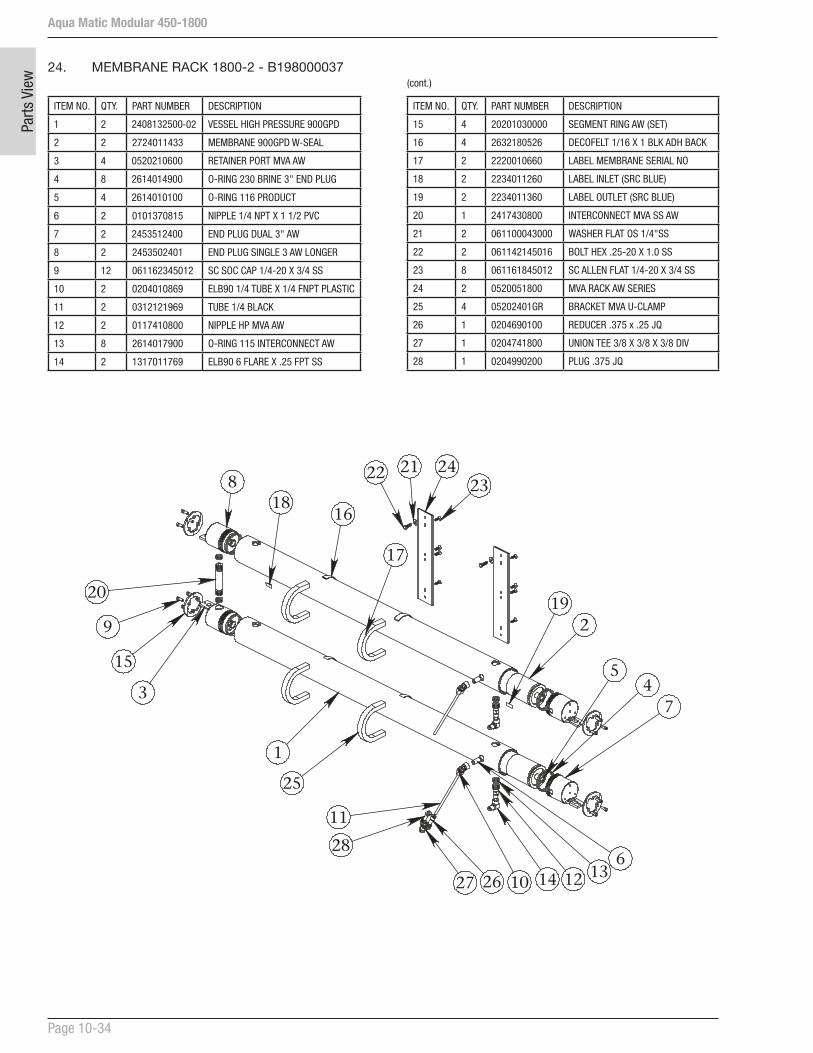
Aqua Matic Modular 450-1800
Page 10-34
Parts
Vie
w
24. MEMBRANE RACK 1800-2 - B198000037
ITEM NO. QTY. PART NUMBER DESCRIPTION
1 2 2408132500-02 VESSEL HIGH PRESSURE 900GPD
2 2 2724011433 MEMBRANE 900GPD W-SEAL
3 4 0520210600 RETAINER PORT MVA AW
4 8 2614014900 O-RING 230 BRINE 3" END PLUG
5 4 2614010100 O-RING 116 PRODUCT
6 2 0101370815 NIPPLE 1/4 NPT X 1 1/2 PVC
7 2 2453512400 END PLUG DUAL 3" AW
8 2 2453502401 END PLUG SINGLE 3 AW LONGER
9 12 061162345012 SC SOC CAP 1/4-20 X 3/4 SS
10 2 0204010869 ELB90 1/4 TUBE X 1/4 FNPT PLASTIC
11 2 0312121969 TUBE 1/4 BLACK
12 2 0117410800 NIPPLE HP MVA AW
13 8 2614017900 O-RING 115 INTERCONNECT AW
14 2 1317011769 ELB90 6 FLARE X .25 FPT SS
ITEM NO. QTY. PART NUMBER DESCRIPTION
15 4 20201030000 SEGMENT RING AW (SET)
16 4 2632180526 DECOFELT 1/16 X 1 BLK ADH BACK
17 2 2220010660 LABEL MEMBRANE SERIAL NO
18 2 2234011260 LABEL INLET (SRC BLUE)
19 2 2234011360 LABEL OUTLET (SRC BLUE)
20 1 2417430800 INTERCONNECT MVA SS AW
21 2 061100043000 WASHER FLAT OS 1/4"SS
22 2 061142145016 BOLT HEX .25-20 X 1.0 SS
23 8 061161845012 SC ALLEN FLAT 1/4-20 X 3/4 SS
24 2 0520051800 MVA RACK AW SERIES
25 4 05202401GR BRACKET MVA U-CLAMP
26 1 0204690100 REDUCER .375 x .25 JQ
27 1 0204741800 UNION TEE 3/8 X 3/8 X 3/8 DIV
28 1 0204990200 PLUG .375 JQ
(cont.)
232122
9
15
8
20
18
17
3
26 14 12
1
2
7
28
11
106
19
27
24
13
45
16
25

Aqua Matic Modular 450-1800
Page 10-35
Parts View
PREFILTRATION CARTRIDGE FILTER ELEMENT WARNING:
Do not use third party Prefiltration Elements (Plankton Filter Elements, Prefilter Elements, Commercial Prefilter Elements, or Oil/Water Separator Elements). Use only Sea Recovery supplied Prefiltration Elements. Third party prefiltration elements on the market do not properly fit into the Sea Recovery Filter Housings, the seams fall apart, and they will allow by-pass resulting in EXTENSIVE AND EXPENSIVE DAMAGE TO THE HIGH PRESSURE PUMP AS WELL AS PREMATURE FOULING OF THE R.O. MEMBRANE ELEMENT.
Damage caused to the Sea Recovery High Pressure Pump, R.O. Membrane Element, or any other component from the use of third party, non Sea Recovery supplied, filter elements is the responsibility and liability of the operator and is not covered by the Sea Recovery Warranty.
FILTER ELEMENT CAUTION:
Do not use “string wound” or “fiber” type prefilter elements. These type of elements are designed for the Photographic Film Developing industry. When used in sea water they will plug up rapidly in 1/10th or less the time causing frequent shut down of the system and very frequent changing resulting in very high cost of maintenance.

Aqua Matic Modular 450-1800
Page 10-36
Parts
Vie
w
25. CONTROLLER BOX A15M
ITEM NO. PART NUMBER DESCRIPTION QTY.
1 B586150003 FRAME ASSY AQMM II 1
2 B619940001 CONTROLLER CHASSIS 1 PH AQMMI 1
3 B595160001 CONTROLLER AQM / AW DX NON CON 1
4 B515150002 LP BACK PLATE ASSY 1
5 B147130002 LP TRANSDUCER MANIFOLD ASSY AQWM/AQMM 1
6 B476160003 BACK PRESS RGLR ASSY AQMMII 1
95
43
5
15
8
6
14
10
11
1
7
1716
13
12
2
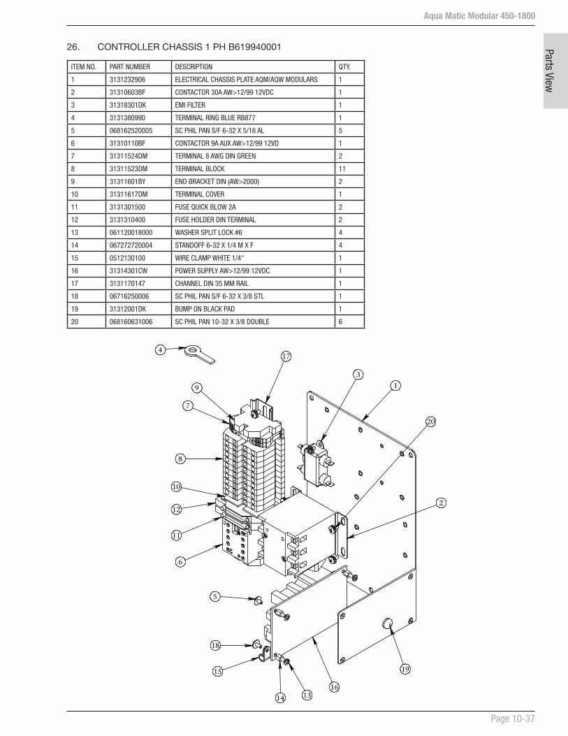
Aqua Matic Modular 450-1800
Page 10-37
Parts View
26. CONTROLLER CHASSIS 1 PH B619940001
ITEM NO. PART NUMBER DESCRIPTION QTY.
1 3131232906 ELECTRICAL CHASSIS PLATE AQM/AQW MODULARS 1
2 31310603BF CONTACTOR 30A AW>12/99 12VDC 1
3 31318301DK EMI FILTER 1
4 3131380990 TERMINAL RING BLUE RB877 1
5 068162520005 SC PHIL PAN S/F 6-32 X 5/16 AL 5
6 31310110BF CONTACTOR 9A AUX AW>12/99 12VD 1
7 31311524DM TERMINAL 8 AWG DIN GREEN 2
8 31311523DM TERMINAL BLOCK 11
9 31311601BY END BRACKET DIN (AW>2000) 2
10 31311617DM TERMINAL COVER 1
11 3131301500 FUSE QUICK BLOW 2A 2
12 3131310400 FUSE HOLDER DIN TERMINAL 2
13 061120018000 WASHER SPLIT LOCK #6 4
14 067272720004 STANDOFF 6-32 X 1/4 M X F 4
15 0512130100 WIRE CLAMP WHITE 1/4" 1
16 31314301CW POWER SUPPLY AW>12/99 12VDC 1
17 3131170147 CHANNEL DIN 35 MM RAIL 1
18 06716250006 SC PHIL PAN S/F 6-32 X 3/8 STL 1
19 31312001DK BUMP ON BLACK PAD 1
20 068160631006 SC PHIL PAN 10-32 X 3/8 DOUBLE 6
18
5
15
1314
1
4
19
3
20
16
2
17
9
7
8
12
11
6
10
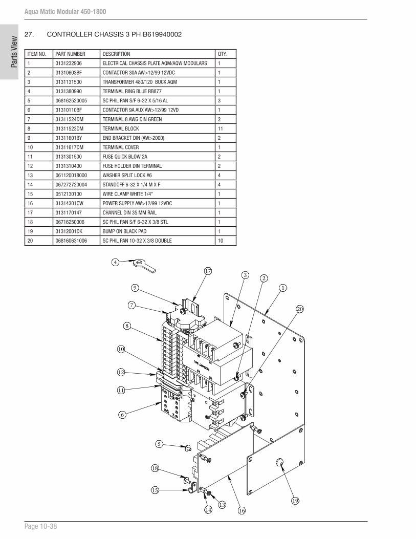
Aqua Matic Modular 450-1800
Page 10-38
Parts
Vie
w
ITEM NO. PART NUMBER DESCRIPTION QTY.
1 3131232906 ELECTRICAL CHASSIS PLATE AQM/AQW MODULARS 1
2 31310603BF CONTACTOR 30A AW>12/99 12VDC 1
3 3131131500 TRANSFORMER 480/120 BUCK AQM 1
4 3131380990 TERMINAL RING BLUE RB877 1
5 068162520005 SC PHIL PAN S/F 6-32 X 5/16 AL 3
6 31310110BF CONTACTOR 9A AUX AW>12/99 12VD 1
7 31311524DM TERMINAL 8 AWG DIN GREEN 2
8 31311523DM TERMINAL BLOCK 11
9 31311601BY END BRACKET DIN (AW>2000) 2
10 31311617DM TERMINAL COVER 1
11 3131301500 FUSE QUICK BLOW 2A 2
12 3131310400 FUSE HOLDER DIN TERMINAL 2
13 061120018000 WASHER SPLIT LOCK #6 4
14 067272720004 STANDOFF 6-32 X 1/4 M X F 4
15 0512130100 WIRE CLAMP WHITE 1/4" 1
16 31314301CW POWER SUPPLY AW>12/99 12VDC 1
17 3131170147 CHANNEL DIN 35 MM RAIL 1
18 06716250006 SC PHIL PAN S/F 6-32 X 3/8 STL 1
19 31312001DK BUMP ON BLACK PAD 1
20 068160631006 SC PHIL PAN 10-32 X 3/8 DOUBLE 10
27. CONTROLLER CHASSIS 3 PH B619940002
18
5
15
1314
1
4
19
20
3
8
12
11
6
9
7
2
10
16
17

Aqua Matic Modular 450-1800
Page 10-39
Parts View
28. BACK PRESSURE REGULATOR ASSY B476160003
ITEM NO. PART NUMBER DESCRIPTION QTY.
1 2020043900 BRACKET MOUNT, BPR AQM II 1
2 1417017896 VALVE PRESS REGULATOR-AS 1
3 B079400004 BPR GEAR ASSY AQM II 1
4 3421020100 COUPLER BACK PRESSURE REG-AQM 1
5 0204021769 ELB90 3/8 TUBE X 1/4 MPT PLASTIC 1
6 061222345006 SC ALLEN SET SCREW 1/4-20 x 3/8 LG 1
7 21010110MC RUBBER MNT BUSHING PVC 8
8 01634109CQ PRESSURE PORT SHAFT AQMM II 1
9 5353140901 PRESSURE PORT MANIFOLD AQMM II 1
10 2317100300 TRANSDUCER 0-2000 PSI 7/16" SAE 1
11 061120023000 WASHER SPLIT LOCK #8 SS 4
12 061162826010 SC PHIL SHLD 8-32 X 1/2 LG SS 4
13 061100043000 WASHER FLAT OS #10 SS 12
14 2020043903 BPR MOUNTING BRACKET AQMM II 1
15 2614017900 O-RING 115 INTERCONNECT AW 4
16 061080023000 WASHER FLAT #8 SS 4
17 061160626012 SC PHIL PAN 8-32 X 3/4 SS 4
18 061160631006 SC PHIL PAN 10-32 X 3/4 SS 6
19 061060031000 NUT HEX 10-32 W/INSERT SS 2
2
5
7
1
3
10
9
8
12
6
18
13
1419
15
4
11
17
16

Aqua Matic Modular 450-1800
Page 10-40
Parts
Vie
w
ITEM NO. PART NUMBER DESCRIPTION QTY.
1 0301094100 PIPE PVC SCH 80 3/8 1
2 11026920AO FLOWMETER IN-LINE .53 - 7.9 GPM 1
3 3131680298 PLUG (CONNECTOR) DIN 3-PIN 1
4 1401095998 VALVE SOLENOID 12VDC AED/CSFE 1
5 01015518HR COUPLER 3/8 FPT X 3/8 FPT PVC 2
6 0204021769 ELB90 3/8 TUBE X 1/4 MPT PLASTIC 1
7 0204021869 ELB90 3/8 TUBE X 3/8 MPT PLASTIC 1
8 11026520AO FLOW METER IN-LINE .13 - 1.3 GPM 1
9 0101551883 ADAP 3/8 SL X 3/8 FPT PVC 3
10 2001043901 MOUNT DIVERSION VALVE AQMMII 1
11 0204121869 CONN 3/8 TUBE X 3/8 FPT PLASTIC 1
12 0312123569 TUBE 3/8 BLACK 1
13 0301094100 PIPE SCH80 PVC AQM II MODULAR 1
14 0101421883 TEE 3/8 FT X 3/8 FT X 3/8 FT PVC 1
15 01013718CL NIPPLE 3/8 NPT X CLOSE PVC 1
29. LP BACK PRESSURE PLATE ASSY B515150002
(cont.)
ITEM NO. PART NUMBER DESCRIPTION QTY.
16 0101191800 ELB90 3/8 SL X 3/8 FNPT PVC 1
17 0103631700 ADAPT 3/8 MPT X 1/4 MPT SCH 40 2
18 0204091969 CONN 3/8 TUBE X 1/2 MPT PLASTIC 1
19 0112651900 ADAP 3/8 MPT X 1/2 BARB NYLON 1
20 0101422583 TEE 1/2 FT X 1/2 FT X 1/2 FT PVC 1
21 0101378500 NIPPLE 3/8 X 5" PVC NPT 1
22 0101292483 RB 1/2 MT X 3/8 FT PVC 1
23 0101322483 RB 1/2 SL X 3/8 SLPVC 1
24 01126526DG ADAP 1/2 MPT X 3/4 BARB NYLON 1
25 0101602583 ADAP 1/2 FPT X 1/2 SL PVC 1
26 B511080004 SALINITY PROBE AQM II 1
27 061160131020 SC PHIL RD 10-32 X 1.25 SS 2
28 061080028000 WASHER FLAT #10 SS 2
29 061170623010 SC PHIL PAN "B" 8 X 5/8 SS 4
13
23
25
24
1
9
7
161514102
5
19
9
11
12
6
9
21
22 2018
26
8
5
17
173
4
2728
29
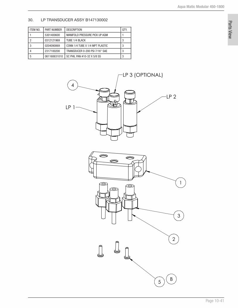
Aqua Matic Modular 450-1800
Page 10-41
Parts View
30. LP TRANSDUCER ASSY B147130002
ITEM NO. PART NUMBER DESCRIPTION QTY.
1 5301400600 MANIFOLD PRESSURE PICK UP AQM 1
2 0312121969 TUBE 1/4 BLACK 3
3 0204090869 CONN 1/4 TUBE X 1/4 MPT PLASTIC 3
4 2317100200 TRANSDUCER 0-200 PSI 7/16" SAE 3
5 061160631010 SC PHIL PAN #10-32 X 5/8 SS 3
4
1
3
2
5
LP 2
LP 3 (OPTIONAL)
LP 1
B
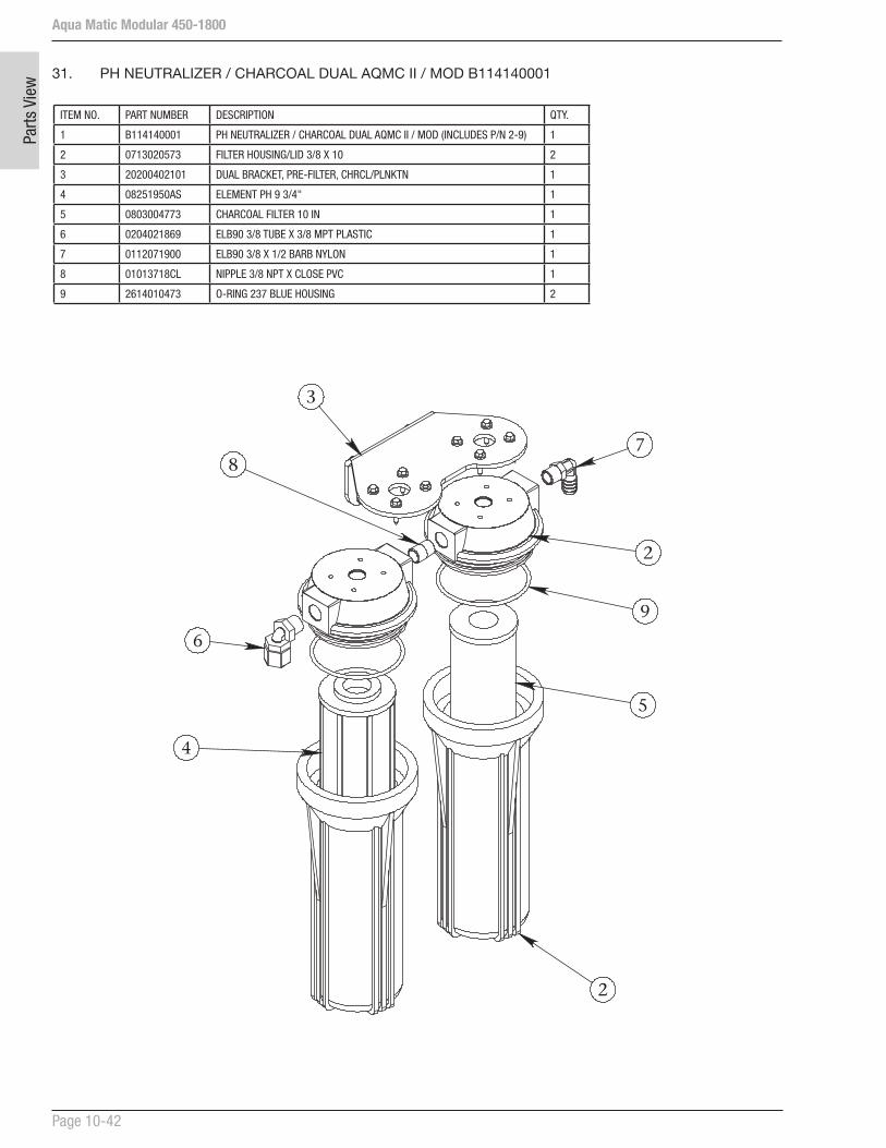
Aqua Matic Modular 450-1800
Page 10-42
Parts
Vie
w
ITEM NO. PART NUMBER DESCRIPTION QTY.
1 B114140001 PH NEUTRALIZER / CHARCOAL DUAL AQMC II / MOD (INCLUDES P/N 2-9) 1
2 0713020573 FILTER HOUSING/LID 3/8 X 10 2
3 20200402101 DUAL BRACKET, PRE-FILTER, CHRCL/PLNKTN 1
4 08251950AS ELEMENT PH 9 3/4" 1
5 0803004773 CHARCOAL FILTER 10 IN 1
6 0204021869 ELB90 3/8 TUBE X 3/8 MPT PLASTIC 1
7 0112071900 ELB90 3/8 X 1/2 BARB NYLON 1
8 01013718CL NIPPLE 3/8 NPT X CLOSE PVC 1
9 2614010473 O-RING 237 BLUE HOUSING 2
31. PH NEUTRALIZER / CHARCOAL DUAL AQMC II / MOD B114140001
3
7
2
2
6
5
4
8
9

Aqua Matic Modular 450-1800
Page 10-43
Parts View
2
4
5 6
3
ITEM PART NUMBER DESCRIPTION QTY U/M
1 B591120001 CLEAN AND RINSE KIT AQM (INCLUDES P/N 2-6) 1 EA
2 14011334AR VALVE 3-WAY BALL 3/4” MPT 2 EA
3 0101063783 ELB90 3/4” FPT X 3/4” BARB PVC 4 EA
4 0501164200 PIPE SUPPORT 1 1/8” #36 4 EA
5 0101613783 ADAP 3/4 FPT X 3/4 BARB PVC 2 EA
6 05181434AA HOSE CLAMP 3/4” SS 12 EA
32. CLEAN AND RINSE KIT AQM B591120001
INLET FEED WATER FROM SEA STRAINER
[4] OUTLET
OUTLET TO BOOSTER PUMP [6] INLET
INLET FEED WATER FROM SEA STRAINER [4] OUTLET
OUTLET TO RINSE/CLEAN BUCKET [44]
INLET BRINE DISCHARGE FROM SYSTEM OUTLET
OUTLET TO BRINE DISCHARGE CONNECTOR [30]
VALVE CONNECTIONS:
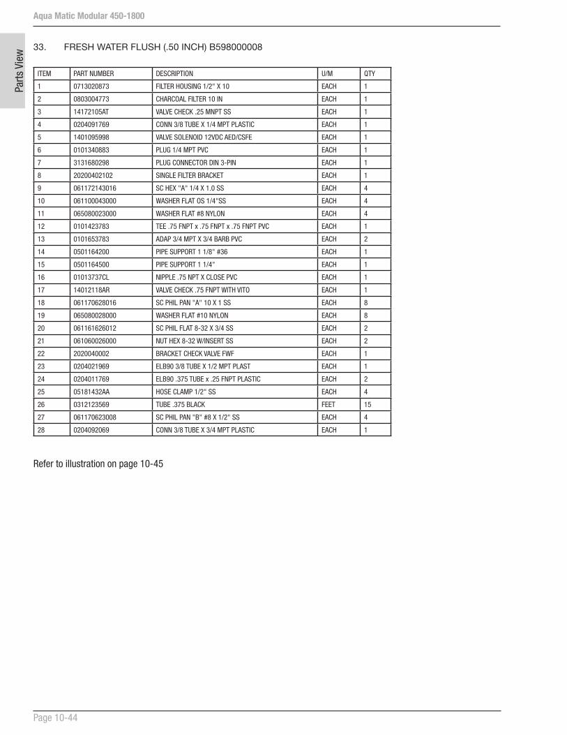
Aqua Matic Modular 450-1800
Page 10-44
Parts
Vie
w 33. FRESH WATER FLUSH (.50 INCH) B598000008
ITEM PART NUMBER DESCRIPTION U/M QTY
1 0713020873 FILTER HOUSING 1/2" X 10 EACH 1
2 0803004773 CHARCOAL FILTER 10 IN EACH 1
3 14172105AT VALVE CHECK .25 MNPT SS EACH 1
4 0204091769 CONN 3/8 TUBE X 1/4 MPT PLASTIC EACH 1
5 1401095998 VALVE SOLENOID 12VDC AED/CSFE EACH 1
6 0101340883 PLUG 1/4 MPT PVC EACH 1
7 3131680298 PLUG CONNECTOR DIN 3-PIN EACH 1
8 20200402102 SINGLE FILTER BRACKET EACH 1
9 061172143016 SC HEX "A" 1/4 X 1.0 SS EACH 4
10 061100043000 WASHER FLAT OS 1/4"SS EACH 4
11 065080023000 WASHER FLAT #8 NYLON EACH 4
12 0101423783 TEE .75 FNPT x .75 FNPT x .75 FNPT PVC EACH 1
13 0101653783 ADAP 3/4 MPT X 3/4 BARB PVC EACH 2
14 0501164200 PIPE SUPPORT 1 1/8" #36 EACH 1
15 0501164500 PIPE SUPPORT 1 1/4" EACH 1
16 01013737CL NIPPLE .75 NPT X CLOSE PVC EACH 1
17 14012118AR VALVE CHECK .75 FNPT WITH VITO EACH 1
18 061170628016 SC PHIL PAN "A" 10 X 1 SS EACH 8
19 065080028000 WASHER FLAT #10 NYLON EACH 8
20 061161626012 SC PHIL FLAT 8-32 X 3/4 SS EACH 2
21 061060026000 NUT HEX 8-32 W/INSERT SS EACH 2
22 2020040002 BRACKET CHECK VALVE FWF EACH 1
23 0204021969 ELB90 3/8 TUBE X 1/2 MPT PLAST EACH 1
24 0204011769 ELB90 .375 TUBE x .25 FNPT PLASTIC EACH 2
25 05181432AA HOSE CLAMP 1/2" SS EACH 4
26 0312123569 TUBE .375 BLACK FEET 15
27 061170623008 SC PHIL PAN "B" #8 X 1/2" SS EACH 4
28 0204092069 CONN 3/8 TUBE X 3/4 MPT PLASTIC EACH 1
Refer to illustration on page 10-45

Aqua Matic Modular 450-1800
Page 10-45
Parts View
25
13
17
15
21
14
16
12
22 19 18
10
97 5
6
8
26
3
4
20
1
2
24
27
11
23
28
FRESH WATER FLUSH (.50 INCH) B598000008 - Illustration

Aqua Matic Modular 450-1800
Page 10-46
Parts
Vie
w
34. UV STERILIZER 12VDC 2GPM B5262000CV
Item No. Part No. Description Qty
1 20010418002A Valve Bracket Clean/Rinse Kit 2
2 20010418001A Bracket Mount Saddle UV-AW Top 2
3 40000306CV UV Sterilizer 2 GPM 12VDC 1
4 40000100CV UV LAMP 2 GPM 1
5 2614019000 O-RING 212 QUARTZ SLEEVE 1
6 0204091869 CONN 3/8 TUBE X 3/8 MPT PLASTIC 1
7 0204021769 ELB90 3/8 TUBE X 1/4 MPT PLASTIC 1
2
1
3
4
56
7
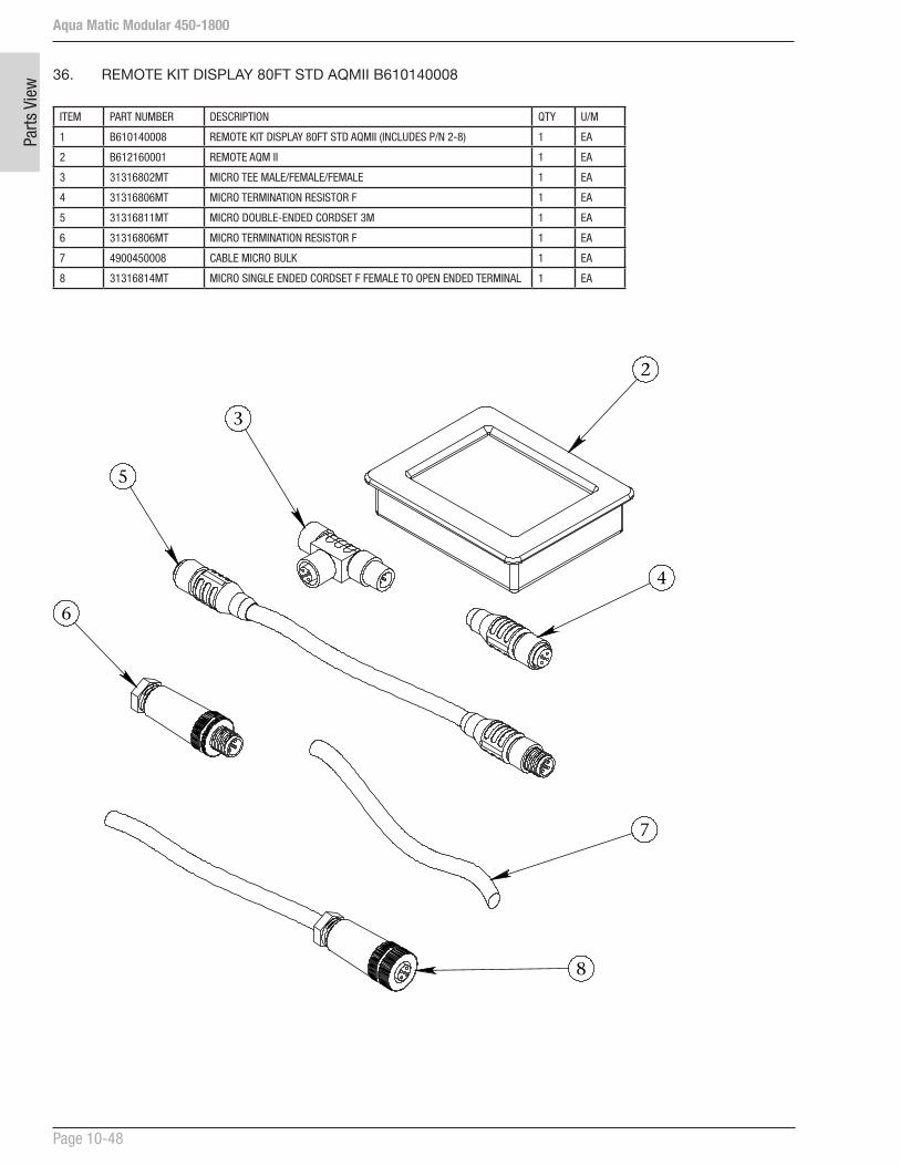
Aqua Matic Modular 450-1800
Page 10-48
Parts
Vie
w 36. REMOTE KIT DISPLAY 80FT STD AQMII B610140008
ITEM PART NUMBER DESCRIPTION QTY U/M
1 B610140008 REMOTE KIT DISPLAY 80FT STD AQMII (INCLUDES P/N 2-8) 1 EA
2 B612160001 REMOTE AQM II 1 EA
3 31316802MT MICRO TEE MALE/FEMALE/FEMALE 1 EA
4 31316806MT MICRO TERMINATION RESISTOR F 1 EA
5 31316811MT MICRO DOUBLE-ENDED CORDSET 3M 1 EA
6 31316806MT MICRO TERMINATION RESISTOR F 1 EA
7 4900450008 CABLE MICRO BULK 1 EA
8 31316814MT MICRO SINGLE ENDED CORDSET F FEMALE TO OPEN ENDED TERMINAL 1 EA
2
4
3
5
6
7
8
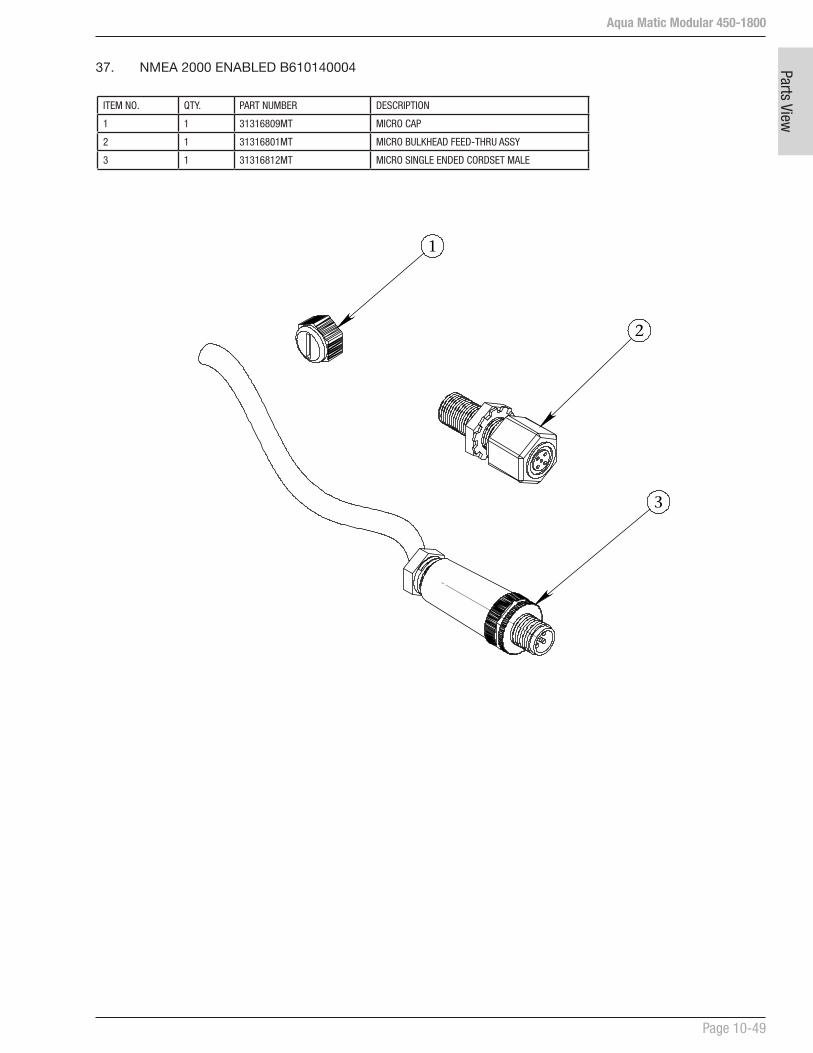
Aqua Matic Modular 450-1800
Page 10-49
Parts View
ITEM NO. QTY. PART NUMBER DESCRIPTION
1 1 31316809MT MICRO CAP
2 1 31316801MT MICRO BULKHEAD FEED-THRU ASSY
3 1 31316812MT MICRO SINGLE ENDED CORDSET MALE
37. NMEA 2000 ENABLED B610140004
1
2
3
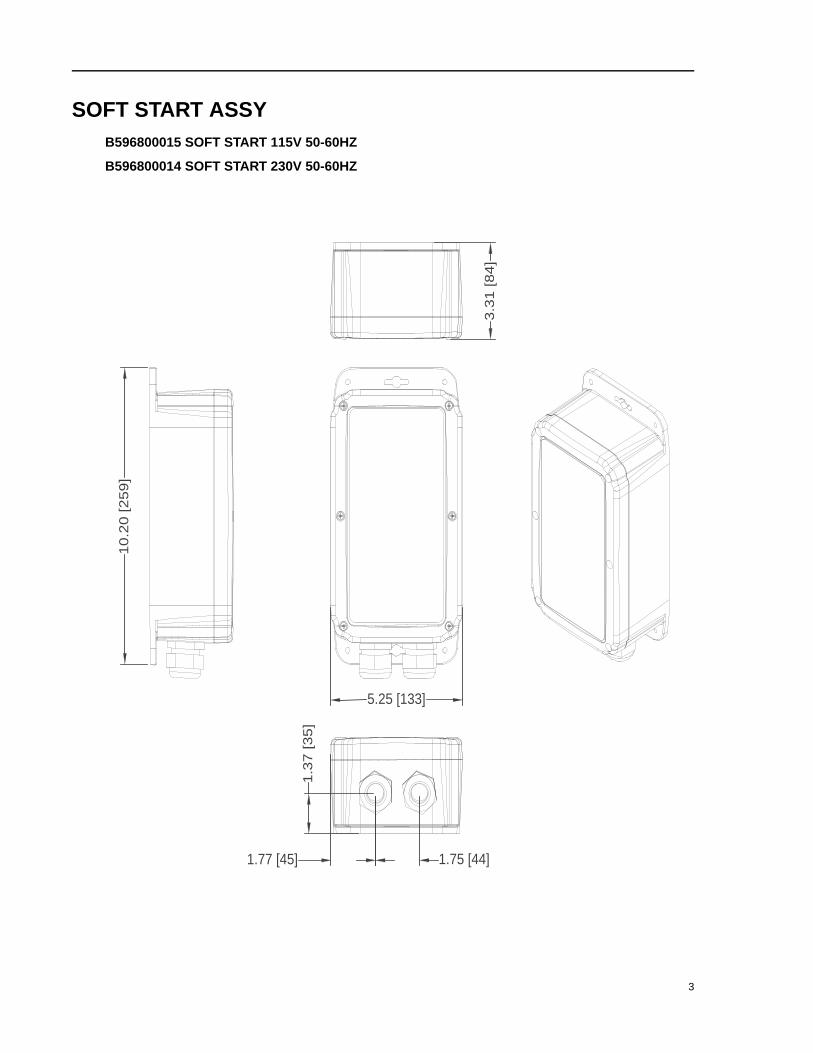
SOFT START ASSYB596800015 SOFT START 115V 50-60HZ
B596800014 SOFT START 230V 50-60HZ
10
.20
[2
59
]
5.25 [133]
3.3
1 [8
4]
1.75 [44]
1.3
7 [3
5]
1.77 [45]
3
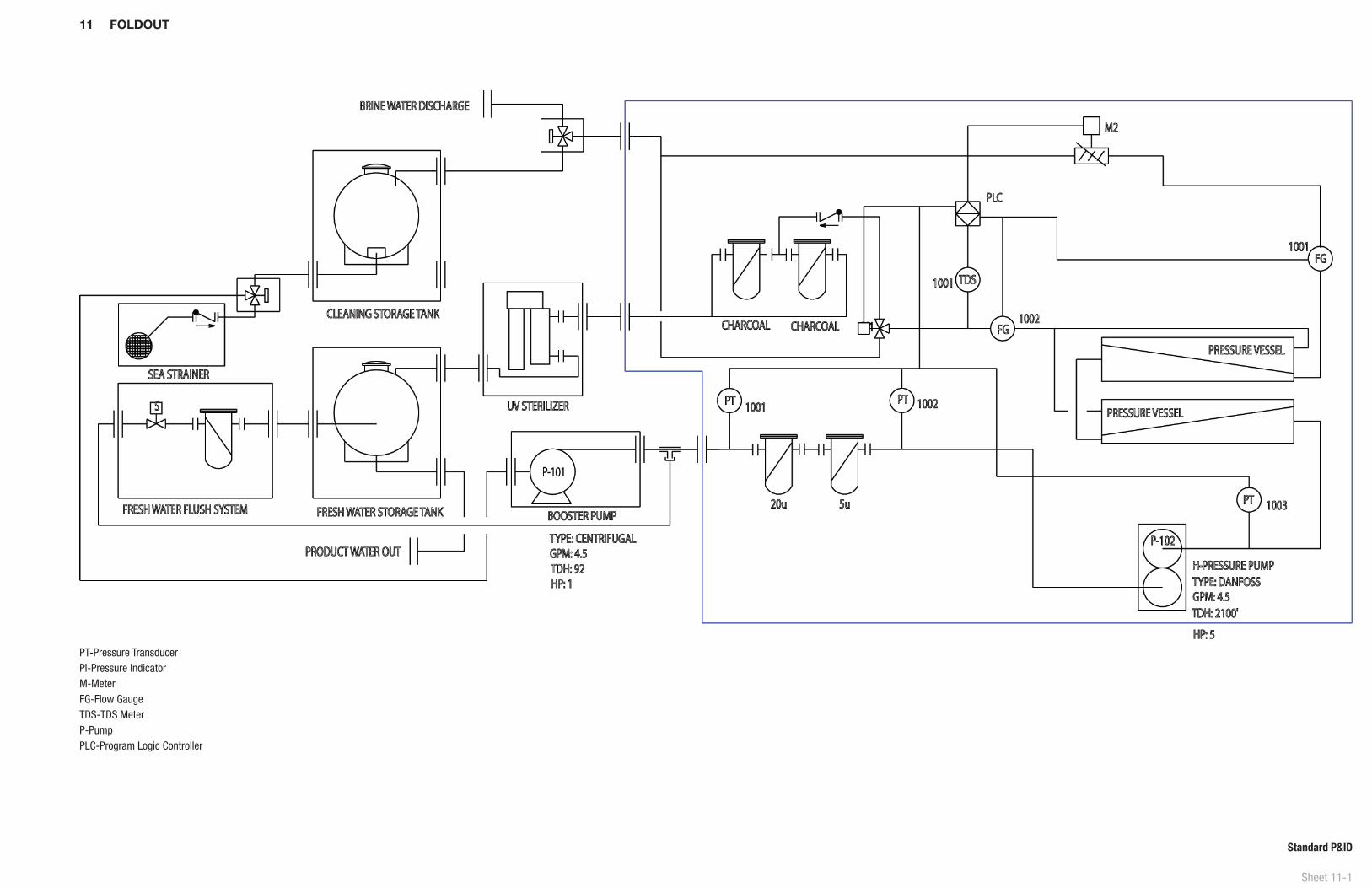
Sheet 11-1
Standard P&ID
PT-Pressure TransducerPI-Pressure IndicatorM-MeterFG-Flow GaugeTDS-TDS MeterP-PumpPLC-Program Logic Controller
11 FOLDOUT
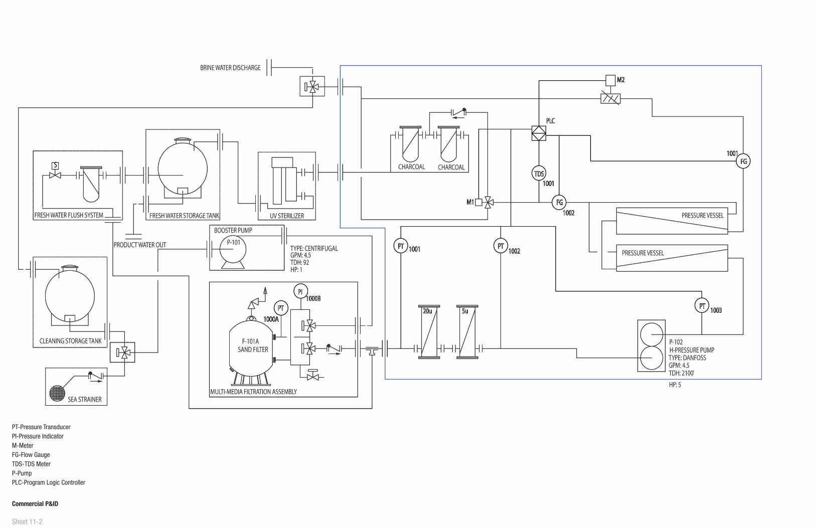
Sheet 11-2
Commercial P&ID
PT-Pressure TransducerPI-Pressure IndicatorM-MeterFG-Flow GaugeTDS-TDS MeterP-PumpPLC-Program Logic Controller


Part Number: B651140002
Sea Recovery Corporation P.O. Box 5288 • Carson, CA 90745-5288 • [email protected]
www.searecovery.com