ar-15 builder’s resource - the guns network llc
TRANSCRIPT
AR-15 Builder’s Resource
Created and Maintained by: JE3146 of Gunsnet.net
Version 1 (rev 1) - © 2006 Jordan Edgar

Table of Contents
Chapter 1 – Tools & Pieces Chapter 2 – Lower Half Assembly Chapter 3 – Upper Half Assembly Chapter 4 – Collapsible Stock Installation Chapter 5 – Fixed Stock Installation Chapter 6 – Headspacing & Function Checks Chapter 7 – Disassembly & Maintenance Chapter 8 – Build Options Chapter 9 – Exploded Diagram

Special Thanks M700Police – Photos of Fixed Stock Installation
Legal This tutorial in no way signifies liability for person or property during assembly or usage. The creator of the AR-15 Builder’s Guide will not be responsible or accountable for, but not limited to, anything that may arise during purchase, assembly, function checks, or usage of anything in some way related to this guide.
Use this guide at your own risk.

Chapter 1 – Tools & Pieces What tools do I need? If you’re considering that you might do a complete build in the future, then it’s recommended to just buy the tools now. It will save you from the expense later, and you’ll have the tools to perform maintenance on the rifle you currently have. Tools such as the telescoping stock wrench are integrated within the Armorer’s wrench. Buying both is not necessary. For a Kit Build:
• Roll Pin Punches (3/32", 1/8", 5/32") • A flathead screwdriver and/or allen key • Hammer • Needle nose Pliers • Telescoping stock wrench (if you have a collapsible stock)
For a Complete Build:
• Roll Pin Punch (1/16") • A vice • Action block • Barrel or Armorer's wrench
Recommended, but not necessary Tools for a Complete Build:
• Gas tube pusher • Snap-Ring pliers • Pivot Pin Detent tool or razor blade
What pieces do I need for a kit build? The following is a list of pieces you will need for a kit build:
• AR-15 kit • AR-15 stripped lower receiver
1

What pieces do I need for a complete build? The following is a list of pieces you will need for a complete build:
• Stripped Lower Receiver • Upper Receiver • Lower Receiver Parts Kit (*) • Bolt Assembly • Charging Handle • Gas Tube & Gas Tube Roll Pin • Delta Ring Assembly • Barrel with Barrel Nut • Handguard • Stock Assembly with Buffer Spring and Buffer • Sight, Optic, or other aiming device if your upper does not include one
(*) Lower Receiver Parts Kit Expanded
• Trigger Guard • Disconnector • Trigger • Bolt Catch • Magazine Catch Button • Magazine Catch • Hammer • Selector • Trigger and Hammer Pins • Takedown and Pivot Detent Springs • Selector Spring • Bolt Catch Spring • Buffer Retaining Spring • Disconnector Spring • Magazine Catch Spring • Trigger Spring • Hammer Spring • Pistol Grip Lock Washer & Screw • Takedown Pin • Pivot Pin • Bolt Catch Roll Pin • Trigger Guard Roll Pin • Buffer Retainer • Bolt Catch Buffer • Selector Detent • Takedown and Pivot Detents
2

Chapter 2 - Lower Half Assembly Lay out the Parts Before starting any project, be sure to layout the parts and make sure you have everything you need. Do the same with your tools. Starting a project and finding out halfway through it, that you don't have the tool you need could pose a problem. On one hand, you could wait until you find, locate, or acquire the tool, or on the other hand you could make due with what you have. Doing the latter poses a great risk and many AR's have been messed up by people being impatient without proper tooling. Take this step seriously.
Courtesy of AR15.com for this picture
All parts will be coated with protective grease. Prior to installation, make sure to clean off this protective grease and coat with a lubricant of your choice. I used BreakFree CLP for this installation. All parts will have very tight tolerances. However, nothing should have to be overly forced into place. If something is not going right, then stop, take another look at the guide, figure out what isn't going right and then start again. The key element to any successful build is PATIENCE. The only parts that need to be hammered into place are the two roll pins.
3

1. The Magazine Catch
CAREFUL - YOU CAN SCRATCH YOUR RECEIVER ON THIS STEP First you insert the Mag Catch Spring into the hole shown. The next step is to insert the Magazine Catch into its hole on the opposite side. Then proceed to stick the MRelease Button into its proper hole shown and depress it downuntil the threads of the Magazine Catch meet the button. Push the button into the hole. This will create spring tension and push the Magazine Catch out the other side.The goal is to thread the MagazCatch onto the button.
ag
ward
ine
4

Once the Magazine Catch is threaded onto the Mag Release Button, you can take a punch (one of the larger ones) and depress the button downward. Rotating the Magazine Catch clockwise will thread it into place. Keep doing this until the threads of the Magazine Catch are flush with the top of the hole on the button. This can be seen a few photos down.
5

Finished Mag Catch
2. The Bolt Catch
CAREFUL - YOU CAN SCRATCH YOUR RECEIVER ON THIS STEP
Insert the Bolt Catch Spring into proper hole on the receiver as shown.
Insert the Bolt Catch Buffer onto the Bolt Catch Spring.
6

Insert the Bolt Catch.
This step is best done with the receiver vertical. Place the Bolt CRoll pin into its proper spot, and givit 1 or two taps with the roll pin punch and a hammer to start it in the hole.
atch e
et
The next part is best done with some form of protection on the receiver. Masking tape, duct tape or a plastic Ziploc bag work nicely for protecting the finish. You will have to line up the Bolt Catch with one hand while tapping the roll pin in with the other. This job requires 3 hands to be done effectively and is sometimes best done with a 2nd person. Once you gthe roll pin going and everything is lined up, you can stand it vertical again to finish it the rest of the way. Don’t push it too far through though.
7

The finished product will look like this.
3. The Trigger Guard
CAREFUL - YOU CAN BREAK YOUR RECEIVER ON THIS STEP
The easiest way to complete this step is to position the "ears" of the receiver onto a book for support. In my example, I've found the ONLY use for a Differential Equations book. My trigger guard may look a little different, but that's nothing to worry about. Find the roll pin and use the (1/8") punch. Go SLOW on this step. Without the receiver on a support, and going too fast could result in breaking the ears off your receiver. That would be bad. Give the pin sold hits, but don't take large swings at it. It will gradually move into place. Once the roll pin is in place, rotate the trigger guard foreword, and the front part will snap into place with a spring loaded pin that comes preinstalled on the trigger guard.
8

4. The Pivot Pin -
TIP: Do this step in a 1 gallon Ziploc bag. If parts fly, and they will for a first timer, then they will be isolated in Ziploc bag. This saves time. Otherwise you'd be hunting a very tiny piece that's now located several feet away and buried in the carpet. A Razorblade works well to hold the pin in place during installation, and a Pivot Pin Detent Installation Tool works even better. First insert the Detent Spring into the hole.
Next insert the Detent onto the Detent Spring. The goal is to get the setup looking like the next photo down. The easiest way to accomplish this is using a flat razor blade to hole the detent pin in the hole, while you slide the pivot pin into place over the top of the detent. Another method is using a pair of needle nose pliers. The final method is using a special 4$ tool. The tool saves headaches, but is not necessary.
Finished Pivot Pin.
9

5. The Trigger
Insert the disconnector spring as shown below. Make sure the "fat" part of the spring is downward. If iis not downward, the disconnectorwon't sit right and you won't getyour trigger pin in right.
t
ext put your Trigger Spring onto
ext put your Trigger Spring onto
Nthe Trigger as shown. Nthe Trigger as shown.
10

Finally place the trigger assembly
o
nd this is the finished product.
6. The Hammer
nly 3 pieces for this step.
into the receiver, and insert the trigger pin. Push downward onto the disconnector to get the holes tline up right. A
O
11

Put the hammer spring onto the
hen insert the hammer egs
t
.
ugh
ce
bad
e
properly installed hammer.
hammer as shown below. Tcorrectly with the spring lsitting atop the trigger pin thayou just installed. Then insert the hammer pin in the same fashion as you did the triggerPush downward on the hammeruntil the holes line up and shove the Hammer Pin throthe receiver. This pin usually is a little tight, so a few VERY light taps from a hammer onthe pin has been started through is generally not aidea. Just make sure not to overly hit it or miss. A very very light tap should be morthan enough. A
12

Carefully lock back the
, but
ur
. The Safety Selector and Pistol Grip
sert the Selector Switch to the proper hole, as
ip the receiver over and sert the Selector Detent,
e
hammer to function testDO NOT let go of the hammeruntil you are fully sure it locks into place. If the hammer releases, it could crack yoreceiver upon impact.
7
Ininshown.
Flinpoint side down, so that thbase of the pin fits nearly flush, as shown.
13

Insert the Selector Spring into the Grip hole, and wiggle the grip
ng
ush the grip down fully.
Find the Grip Screw and make sure the washer is in place. The Grip Screw may either require a
onto the receiver lining the spriup with the Selector Detent hole.
P
flathead screwdriver or an allenkey pending on the make of the Lower Parts Kit.
14

Screw the grip down tightly.
inished Lower Receiver
his is what your finished receiver will look like. The remaining parts will be installed uttstock. Be sure not to lose them as there is no way to
stall them on the lower receiver without a buttstock.
F Tlater when you attach your bin
15

Chapter 3 - Upper Half Assembly Lay out the Parts Before starting any project, be sure to layout the parts and make sure you have everything you need. Do the same with your tools. Starting a project and finding out halfway through it, that you don't have the tool you need could pose a problem. On one hand, you could wait until you find, locate, or acquire the tool, or on the other hand you could make due with what you have. Doing the latter poses a great risk and many AR's have been messed up by people being impatient without proper tooling. Take this step seriously.
16
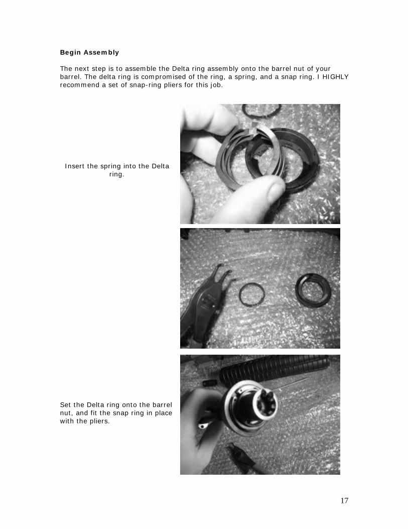
Begin Assembly The next step is to assemble the Delta ring assembly onto the barrel nut of your barrel. The delta ring is compromised of the ring, a spring, and a snap ring. I HIGHLY recommend a set of snap-ring pliers for this job.
Insert the spring into the Delta ring.
Set the Delta ring onto the barrel nut, and fit the snap ring in place with the pliers.
17

With the delta ring on. Place your receiver in the action block.
Place the block in a vice. Insert your barrel into the receiver. If there is extreme resistance, then remove the barrel and rub steel wool on the outside of the barrel, where it wslip into the receiver.
ill
Sometimes the parkerization can be a little thick.
18

Coat the threads with a form of moly based grease (*) to prevent any form of seizing from occurring. Screw the barrel nut onto the receiver threads until hand tight. (*) NOTHING WITH A GRAPHITE ADDITIVE! Now take the wrench and tighten the nut just a LITTLE bit. Enough for it to grab hold. The next step is to index the slots on the snap ring and delta ring spring. Make sure they align on the top most part of the receiver. A small punch works best for twisting them around. Next push the gas tube from the rear and push it through the indexed snap ring and spring, but NO further than that. This will keep your snap ring and spring in alignment while you do your final torquing.
19

Finish Assembly Using the barrel wrench, torque the nut to ~ 30 ft lbs. A rule of thumb is to tighten the barrel till it's hand tight, then tighten the nut until the next slot on the barrel nut aligns with the indexed snap ring and spring holes. A torque wrench can be used, but it's not necessary. After torquing the nut, align the hole on the delta ring to see completely through the indexed snap ring, spring, delta ring, and barrel nut. When everything is aligned with the hole on the receiver, remove the gas tube. Feed the gas tube from the muzzle end through the barrel nut, and through the receiver. Wiggle it around the front sight post. It will be a tight fit, but the kink in the gas tube will provide enough clearance. Push it foreword and make sure the gas port on the tube is downward. Feed it into the front sight post, and push it foreword until it is completely in. Using a small punch, you can index the hole of the front sight post with the hole in the gas tube. Insert the roll pin, and using a 1/16" punch, tap in the roll pin.
20

Chapter 4 - Collapsible Stock Installation Lay out the Parts
Parts Needed:
• Complete Lower Receiver minus Stockset Assembly • Stock Body • Buffer Tube • Buffer Spring • Buffer • Castle Nut • Retainer Plate • Rear Takedown Pin • Rear Takedown Detent • Rear Takedown Detent Spring • Buffer Retainer • Buffer Retaining Spring
21

Begin Installation Thread the castle nut on with the notches outward, and place the retainer plate on the buffer tube with the dimple inward towards the receiver. Thread the buffer tube onto the receiver. Screw it on for a couple turns, but nothing more. Insert the Buffer Retaining Spring into the Buffer Retainer.
22

Insert the Buffer Retaining Assembly into the receiver as shown. (Spring side down) Depress the Buffer Retaining Assembly into the receiver while continuing to screw the Buffer Tube onto the receiver. Continue to do this until you can no longer do so. The next step is to place the Rear Takedown Pin into its hole. Make sure the side with the internal groove is facing rearward.
23

On the rearward portion of the receiver you’ll find a small hole. Insert the Takedown Detent into the hole (pointed end first). Then insert the Takedown Detent Spring into the hole. Make sure the Castlenut is as unscrewed as it possibly can be, then proceed to pull the retainer plate towards it. Unscrew the buffer tube slightly until everything’s alignment resembles the picture on the right. Push the retainer plate towards the receiver and then finger tighten the Castlenut. Take your Stock Wrench and fully tighten the Castlenut. Attach your stock body to the buffer tube. Most of the time this is done for you already. To do this properly, rather than depressing the latch on the stock, pull it away from the stock to give the internal pin greater clearance, and slide the Stockset onto the tube until it latches securely.
24

Finish Installation Insert the buffer spring and buffer into the tube and let the Buffer Retainer catch the buffer as show. This will complete the installation of the Collapsible Stockset.
25

Chapter 5 - Fixed Stock Installation Lay out the Parts
Parts Needed:
• Complete Lower Receiver minus Stockset Assembly • Buffer Tube • Buttcap Spacer • Buttstock Screw • Rear Takedown Pin • Rear Takedown Detent • Rear Takedown Detent Spring
ining Spring • Buttstock
• Buffer Retainer • Buffer Reta
26

sert the Buffer Retaining Spring to the Buffer Retainer.
ssembly into the receiver as hown. (Spring side down)
to the receiver. Continue to o this until you can no longer do o.
Inin Insert the Buffer Retaining As Depress the Buffer Retaining Assembly into the receiver while continuing to screw the Buffer Tube onds
27
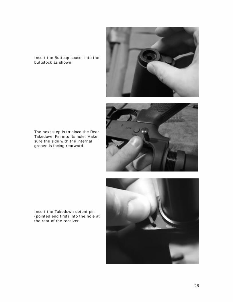
Insert the Buttcap spacer into the uttstock as shown.
e Rear akedown Pin into its hole. Make re the side with the internal
roove is facing rearward.
sert the Takedown detent pin ointed end first) into the hole at e rear of the receiver.
b The next step is to place thTsug
In(pth
28

Insert the spring next.
lace the buttstock onto the buffer be, and slide it into place,
ompressing the spring properly.
lace the screw into the hole at the nd of the buttstock.
Ptuc Pe
29

Screw it down tight with a athead screwdriver.
M700Police’s SPR clone
fl Finished Installation
30

Chapter 6 - Headspacing & Function Checks Headspacing The AR system is very unique in the regard that the bolt is cut to a spec and that the barrel is cut to a spec. The thing that determines headspace on an AR-15 is the barrel extension. This barrel extension comes pre-indexed from the factory. If your barrel and bolt are both made to spec, then there is no reason it should be out of headspace. Remember to buy quality components and you won’t have an issue. There are 3 headspace gauges on the market. The GO, the NO-GO, and the FIELD gauges. ANNUAL (or every 2k rounds) checks are recommended using a FIELD gauge. If your bolt closes on a FIELD gauge, replace the bolt with a new bolt and try again. If it fails with the new bolt, replace the barrel with a new barrel and put the old bolt back on. If it fails that test, put the new bolt back on and stick with that. For a new build, if you so choose to even bother checking its headspace, the bolt should close on a GO gauge, and not close on a NO-GO gauge. NOTE: Do NOT use commercial gauges. Use ones intended for the AR-15/M16 platform. The can be purchased at places like Bushmaster.com Headspacing Chart
Bolt Barrel Headspace Brand New Brand New PERFECT Brand New Lightly Used GOOD Brand New Heavily Used FINE Lightly Used Brand New FINE Lightly Used Lightly Used FINE Lightly Used Heavily Used CHECK Heavily Used Brand New CHECK Heavily Used Lightly Used CHECK Heavily Used Heavily Used CHECK
31

Function Checks Congratulations on your new build. Now let’s make sure it works properly. For starters, make sure the rifle is UNLOADED. Start by laying your new build down in front of you. Double check that it is UNLOADED. Turn the selector to SAFE and pull the trigger. The hammer should NOT drop. Turn the selector to FIRE/SEMI and pull the trigger. The hammer should drop. After it has dropped. Pull the trigger again. Nothing should happen. Try to rotate the selector back to SAFE. If it’s working properly, the rifle will not be able to return to SAFE. Pull bthe charging handle fully to reset the hammer. Now put the rifle back on SAFE. This time it should work.
ack
32

Pull the charging handle back while holding onto the bolt catch (the bottom tab of it). Once you feel it click into place, you can release your hand from the charging handle. If it works, the bolt will remain held in place. If you flip the rifle over, the ejection port should look like this. Empty with the bolt held in place. Flip the rifle back over and press the bolt catch release. The bolt should release and slam foreword. This will not hurt your rifle so do not be alarmed.
33
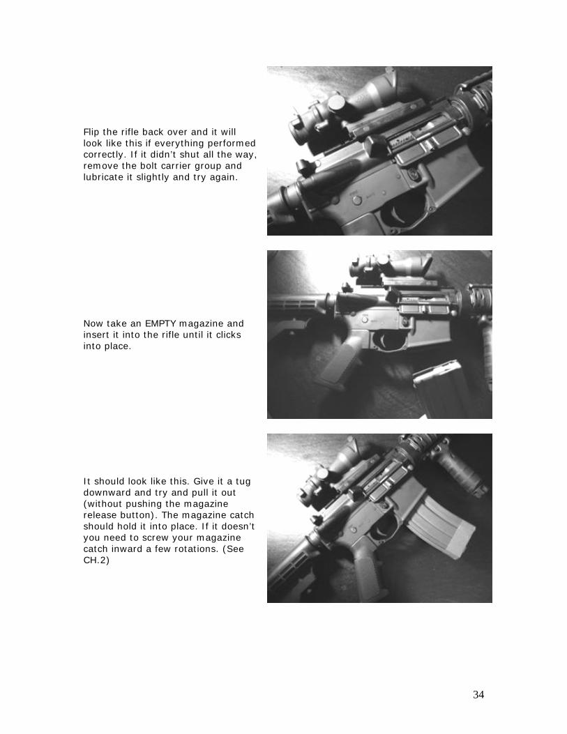
Flip the rifle back over and it will look like this if everything performed correctly. If it didn’t shut all the way, remove the bolt carrier group and lubricate it slightly and try again. Now take an EMPTY magazine and insert it into the rifle until it clicks into place. It should look like this. Give it a tug downward and try and pull it out (without pushing the magazine release button). The magazine catch should hold it into place. If it doesn’t you need to screw your magazine catch inward a few rotations. (See CH.2)
34

Now pick the rifle up and press the magazine release button. The magazine should drop free. If the magazine does not release at all, Unscrew your magazine catch a rotation or two. (See CH.2) If the magazine does not drop free even though it is released, it might not be in spec. Put the EMPTY magazine back into the rifle and pull back on the charging handle. The bolt should lock back. If it doesn’t the magazine spring could bweak, or there could be somwrong with your bolt catch. Deprthe bolt catch a few times to loosen it up and try this again.
e ething
ess
35

You’re now ready to test fire. Start
ill
ak
s you
tart by loading 1 round of and
or
p
ext load 3 rounds of ammunition
ress
ng
ot.
by getting some QUALITY brass cased ammunition. 200 rounds wbe sufficient for a Chrome Lined barrel break in. Do not clean the bore during the Chrome Lined brein. This will allow the chrome to polish. For a Chrome-Moly or Stainless barrel break in. Do aplease. Make sure your rifle is clean of any factory preservative oil, and properly lubricated. Sammunition into a magazineloading your rifle. Pull the charginghandle completely to the rear, and let go of it completely. The round should chamber. Rotate the SelectSwitch from SAFE to FIRE and pull the trigger. The bolt should lock back. Put the SAFETY on and drothe magazine. Ninto your magazine. Insert the magazine into the rifle, and depthe Bolt Catch Release button to release the bolt. The round shouldchamber. Fire 3 shots. If the rifle malfunctions, stop what you’re doiand consult the forums. The bolt should lock back after the third shIf nothing went wrong, resume your break in procedure and have fun with your new rifle!
36

Chapter 7 - Disassembly & Maintenance Disassembly This tutorial will show you how to properly field strip your AR-15.
Lay your UNLOADED rifle on a table to begin. Double check the safety is ON. Push the rear takedown out from left to right. It might be stiff, so you can use the cap from a ballpoint pen or the tip of a bullet to push it free. Pivot the upper a bit so it looks like the photo.
37
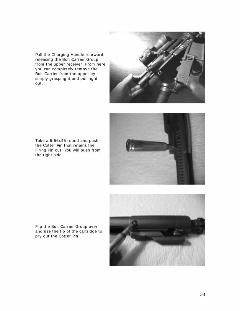
Pull the Charging Handle rearward releasing the Bolt Carrier Group from the upper receiver. From here you can completely remove the Bolt Carrier from the upper by simply grasping it and pulling it out. Take a 5.56x45 round and push the Cotter Pin that retains the Firing Pin out. You will push from the right side. Flip the Bolt Carrier Group over and use the tip of the cartridge to pry out the Cotter Pin.
38

It will look like this when that is complete. From here, stand the Bolt Carrier Group vertical, so the Bolt is on top, and the firing pin will fall out the bottom. To reinstall, just push it into the Bolt Carrier Group, tip first, just like the way it came out. When that is complete, feel free to clean off your firing pin with a rag and some CLP.
39

Push the Bolt all the way into the Carrier and rotate the Cam Pin (The rectangular pin) until it looks like the photo. When you reassemble, the Cam Pin will need to be rotated 90 degrees clockwise or counter-clockwise after insertion to be properly aligned for the re-installation of the firing pin. After the Cam Pin is in place and properly rotated, pull the Bolt to the left so it is sticking all the way out. This will ensure that you can properly reinstall your Firing Pin. Next pull out the Cam Pin. When you reinstall the Cam Pin, the hole in the Bolt will only allow it to be inserted one way. Since there is a hole on each side of the Bolt, try one side, then rotate the Bolt 180 degrees and try the other if the first didn’t allow the Cam Pin to slide in. Then pull out the Bolt. To reinstall, just push it straight in like you tit out.
ook
40

Proceed to take the Firing Pin and use it to push out the Extractor Pin from the Bolt. Finally, pull the Extractor off of the Bolt. Cleaning From here, give the Extractor, the Bolt, and the entire Bolt Carrier a good cleaning. Make sure to lubricate each piece with a good quality CLP like BreakFree CLP. Reinstall everything in reverse order and pay attention to the reinstallation instructions where applicable. Before inserting the Bolt Carrier Group back into the Upper Receiver, be sure to clean out the interior of the Upper Receiver and to clean out the bore with a cleaning rod and brush/patches or a Boresnake. If you wish to give your bore a light coat of gun oil, that is fine, but don’t get overzealous. Use oil sparingly in the bore and chamber, if at all. When everything is cleaned and reassembled, do a quick function check to ensure everything is working properly.
41

Maintenance Certain pieces of your rifle will wear quicker than others. This is a recommended outline of when you should replace or examine certain parts. This is not the rule, and definitely may not apply to every case or every rifle, but should serve as an outline of when to either inspect for damage or replace for peace of mind. This list doesn’t include everything. If anything ever looks damaged that you are unsure of, then consult the forums for advice.
Part When to Inspect Cost to Replace
Bolt / Barrel
Inspect headspace annually (See CH.6) or every 2 thousand rounds
Varies
Cam Pin
Every time you clean the rifle. If it appears well worn, replace it.
5$
Cotter Pin
Every time you clean the rifle. If it appears well worn, replace it.
1$
Firing Pin
Every time you clean the rifle. If the tip appears broken or worn, replace it.
7$
Extractor
Every time you clean the rifle. If it appears well worn, replace it.
13$
Extractor Spring
Every 5 to 10 thousand rounds or if it becomes compressed.
1$
Buffer Spring
Every 5 to 10 thousand rounds or if it becomes compressed.
5$
Buffer Retainer
If it appears worn or damaged, replace it.
1$
Hammer Spring
Every 10 thousand rounds or if it becomes compressed.
1$
42

Chapter 8 - Build Options Where to Start One of the great things about AR-15’s is the ability to create an entirely unique looking rifle out of parts that you choose and want. This is a number of different specifications that can get the ball rolling on which type of build you wish to pursue. This list doesn’t include everything, but it should give you a foundation of where to start. Receiver Options A1 – Old style upper with carry handle. Ghost ring sights adjustable with a bullet. A2 – Modern style upper with carry handle. Ghost ring sights adjustable with knob. A3/A4 – Flat top upper with picatinny rail on top. Detachable A2 Carry Handle – Optional upgrade for A3/A4 receiver. Platform Options SBR AR-15 – Requires NFA Form 1. Less than 16” barrel. Typically configured with either 10.5”, 11.5” or 12.5” barrels. Pistol Caliber Carbine – Typically 9mm. Requires new buffer, hammer and magwell block to accept pistol caliber magazines. Typically uses a smaller ejection port and cut down dust cover. CAR-15 Clone – Usually A1 or A2 receiver. 16” CAR profile barrel with 4 position CAR stock. M4 Clone – M4 “notched” barrel. Typically A2 or A3/A4 receiver. Usually 14.5” with permanently attached flash suppressor 1.5” or longer or 16” with an A2 flash suppressor. Midlength – 16” CAR profile barrel with Midlength gas system. This is slightly longer than a Carbine length gas system. Uses Midlength handguards. Dissipator – 16” barrel with a rifle length sight. The sight block is very close to the muzzle. Typically uses either a carbine or rifle length gas system. The carbine length gas system utilizes a secondary gas block that rests beneath the rifle length handguards. M16A2/A4 Clone – 20” Rifle profile barrel. Rifle length gas system and rifle handguards. It’s a clone of our typical service rifle.
43
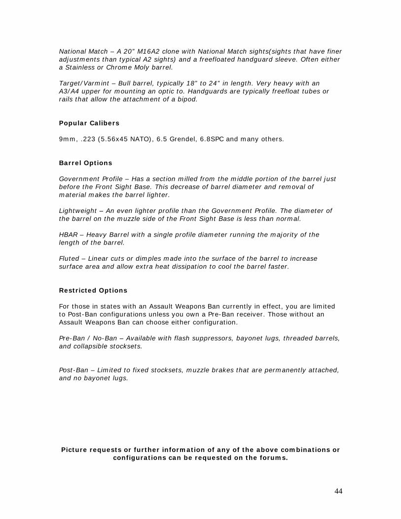
National Match – A 20” M16A2 clone with National Match sights(sights that have finer adjustments than typical A2 sights) and a freefloated handguard sleeve. Often either a Stainless or Chrome Moly barrel. Target/Varmint – Bull barrel, typically 18” to 24” in length. Very heavy with an A3/A4 upper for mounting an optic to. Handguards are typically freefloat tubes or rails that allow the attachment of a bipod. Popular Calibers 9mm, .223 (5.56x45 NATO), 6.5 Grendel, 6.8SPC and many others. Barrel Options Government Profile – Has a section milled from the middle portion of the barrel just before the Front Sight Base. This decrease of barrel diameter and removal of material makes the barrel lighter. Lightweight – An even lighter profile than the Government Profile. The diameter of the barrel on the muzzle side of the Front Sight Base is less than normal. HBAR – Heavy Barrel with a single profile diameter running the majority of the length of the barrel. Fluted – Linear cuts or dimples made into the surface of the barrel to increase surface area and allow extra heat dissipation to cool the barrel faster. Restricted Options For those in states with an Assault Weapons Ban currently in effect, you are limited to Post-Ban configurations unless you own a Pre-Ban receiver. Those without an Assault Weapons Ban can choose either configuration. Pre-Ban / No-Ban – Available with flash suppressors, bayonet lugs, threaded barrels, and collapsible stocksets. Post-Ban – Limited to fixed stocksets, muzzle brakes that are permanently attached, and no bayonet lugs. Picture requests or further information of any of the above combinations or
configurations can be requested on the forums.
44
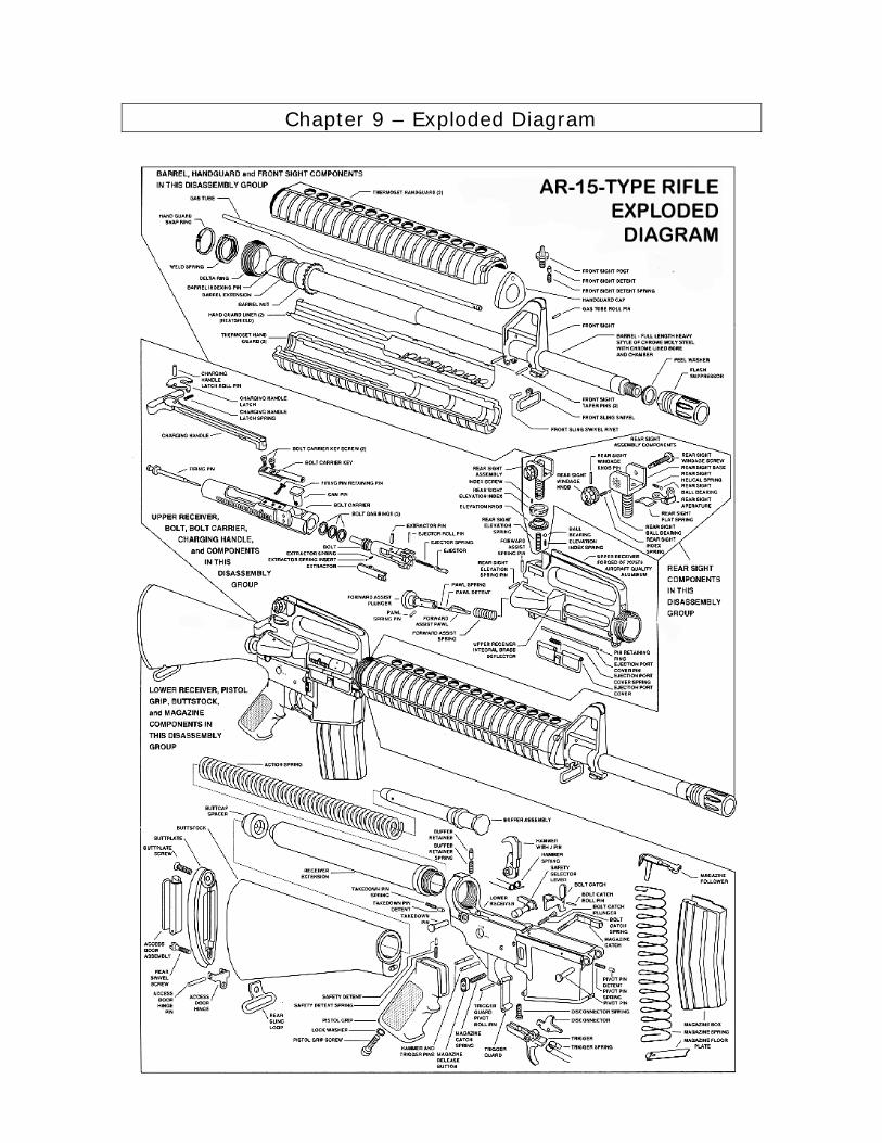
Chapter 9 – Exploded Diagram