arcgis geodatabases
TRANSCRIPT
ArcGIS Geodatabases
ENTERPRISE ARCHITECT
User Guide Series
Author: Sparx Systems
Date: 2021-09-02
Version: 15.2
CREATED WITH
Table of Contents
ArcGIS Geodatabases 3Getting Started 4Example Diagram 7Modeling with ArcGIS 8
ArcGIS Toolbox Pages 10Connectivity Rule Examples 15Topology Example 17Relationship Rule Example 19
Setting ArcGIS Coordinate Systems 21Applying ArcGIS Stereotypes to Abstract Classes 25
Importing ArcGIS XML Workspaces 28Exporting ArcGIS XML Workspaces 30Export Modular ArcGIS Schemas 32Validate ArcGIS Workspaces 38More Information 39
ArcGIS Geodatabases 2 September, 2021
ArcGIS Geodatabases
Exchange, Model and Visualize ArcGIS Geodatabases
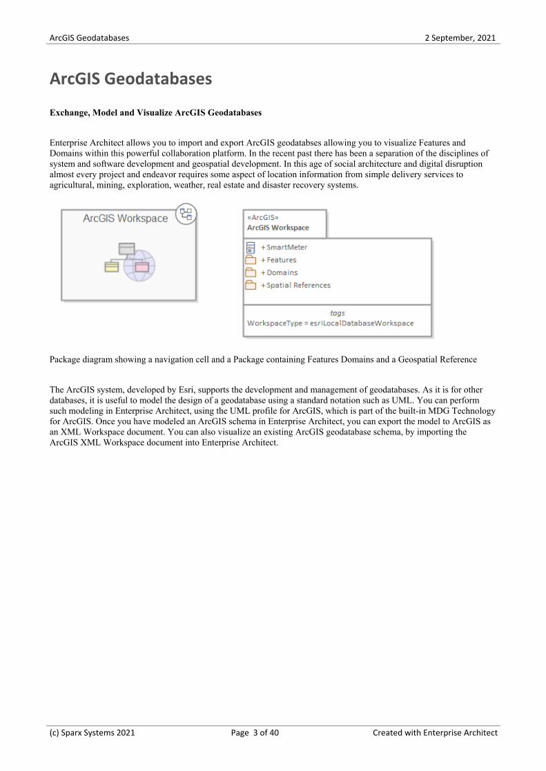
Enterprise Architect allows you to import and export ArcGIS geodatabses allowing you to visualize Features andDomains within this powerful collaboration platform. In the recent past there has been a separation of the disciplines ofsystem and software development and geospatial development. In this age of social architecture and digital disruptionalmost every project and endeavor requires some aspect of location information from simple delivery services toagricultural, mining, exploration, weather, real estate and disaster recovery systems.
Package diagram showing a navigation cell and a Package containing Features Domains and a Geospatial Reference
The ArcGIS system, developed by Esri, supports the development and management of geodatabases. As it is for otherdatabases, it is useful to model the design of a geodatabase using a standard notation such as UML. You can performsuch modeling in Enterprise Architect, using the UML profile for ArcGIS, which is part of the built-in MDG Technologyfor ArcGIS. Once you have modeled an ArcGIS schema in Enterprise Architect, you can export the model to ArcGIS asan XML Workspace document. You can also visualize an existing ArcGIS geodatabase schema, by importing theArcGIS XML Workspace document into Enterprise Architect.
(c) Sparx Systems 2021 Page 3 of 40 Created with Enterprise Architect

ArcGIS Geodatabases 2 September, 2021
Getting Started
Using the ArcGIS features in Enterprise Architect you can visualize geodatabases inside this powerful system andcollaboration platform. This allows you to unify teams working in traditional software centric and engineering systemswith your geospatial teams defining features and domains. Teams defining the strategy business rules and requirementsfor a system or the components that deliver the system functionality can share models with the geospatial teams creatingan integrated model that will help with integration and risk reduction. The multidisciplinary teams can communicate andcollaborate using the powerful collaboration features including chat, discussion and reviews insuring that the geospatialcomponents are well-considered during the strategy, specification, analysis, design, implementation and support of theoverall system.
ArcGIS diagram showing a trace between a Smart Meter and a formal system requirement.
In this topic you will learn how to work with the powerful features that support ArcGIS geodatabases outlined in thefollowing sections.
Selecting the Perspective
Enterprise Architect partitions the tools extensive features into perspectives this ensures that you can focus on a specifictask and work with the tools you need without the distraction of other features. To work with the ArcGIS Geodatabasesfeatures you first need to select the following perspective:
Database Engineering > ArcGIS
Setting the perspective ensures that the ArcGIS diagrams and their tool boxes and other features of the perspective willbe available by default.
Example Diagram
(c) Sparx Systems 2021 Page 4 of 40 Created with Enterprise Architect

ArcGIS Geodatabases 2 September, 2021
An example diagram provides a visual introduction to the topic and allows you to see some of the important elementsand connectors that are created in specifying or describing an ArcGIS geodatabase schema including Features andDomains. Diagrams in other topics will show how Spatial References, Geometric Network and Topology can be modeledin the tool.
Modeling with ArcGIS
This topic introduces the ArcGIS profile which covers the diagrams, toolboxes and elements that you will work withincluding connectivity rules and topologies. You are able to select the ArcGIS perspective from the Geospatial groupwhich will set the tool up for modeling geodabases.
Importing ArcGIS XML Workspaces
This functionality allows you to import an ArcGIS workspace which is an XML document that contains the geodatabaseschema. Any number of schemas can be imported and then layout tools can be used to show or hide features, includingthe ability to show or hide ArcGIS System features.
AcrGIS menu options on the Specialize ribbon to Import an ArcGIS Workspace.
Exporting ArcGIS XML Workspaces
You can model ArcGIS geodatabse schemas in Enterprise Architect and when you are happy that they have beenelaborated correctly, including adding Features and Coded Value and Range domains,they can be exported to an XMLdocument which in turn can be imported into the Esri tool.
Export Modular ArcGIS Schemas
In Enterprise Architect, you can export discreet parts of schemas. This is useful if you have a large geodatabase schema,for example a schema defined as part of an industry reference model. Individual Features (elements) can be exportedusing this facility allowing you to incrementally build up a geodatabase
Validate ArcGIS Workspaces
Enterprise Architect provides a powerful validation services that allows you to check whether the models that youdevelop are compliant with a set of inbuilt system rules for well-formed models.
(c) Sparx Systems 2021 Page 5 of 40 Created with Enterprise Architect
ArcGIS Geodatabases 2 September, 2021
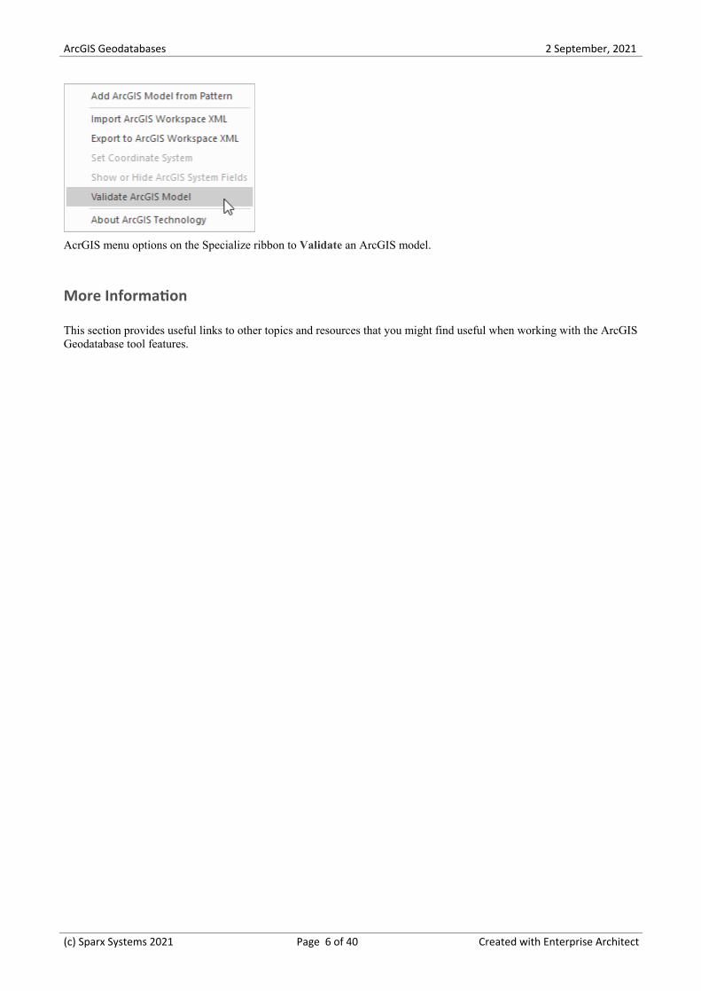
AcrGIS menu options on the Specialize ribbon to Validate an ArcGIS model.
More Information
This section provides useful links to other topics and resources that you might find useful when working with the ArcGISGeodatabase tool features.
(c) Sparx Systems 2021 Page 6 of 40 Created with Enterprise Architect
ArcGIS Geodatabases 2 September, 2021
Example Diagram
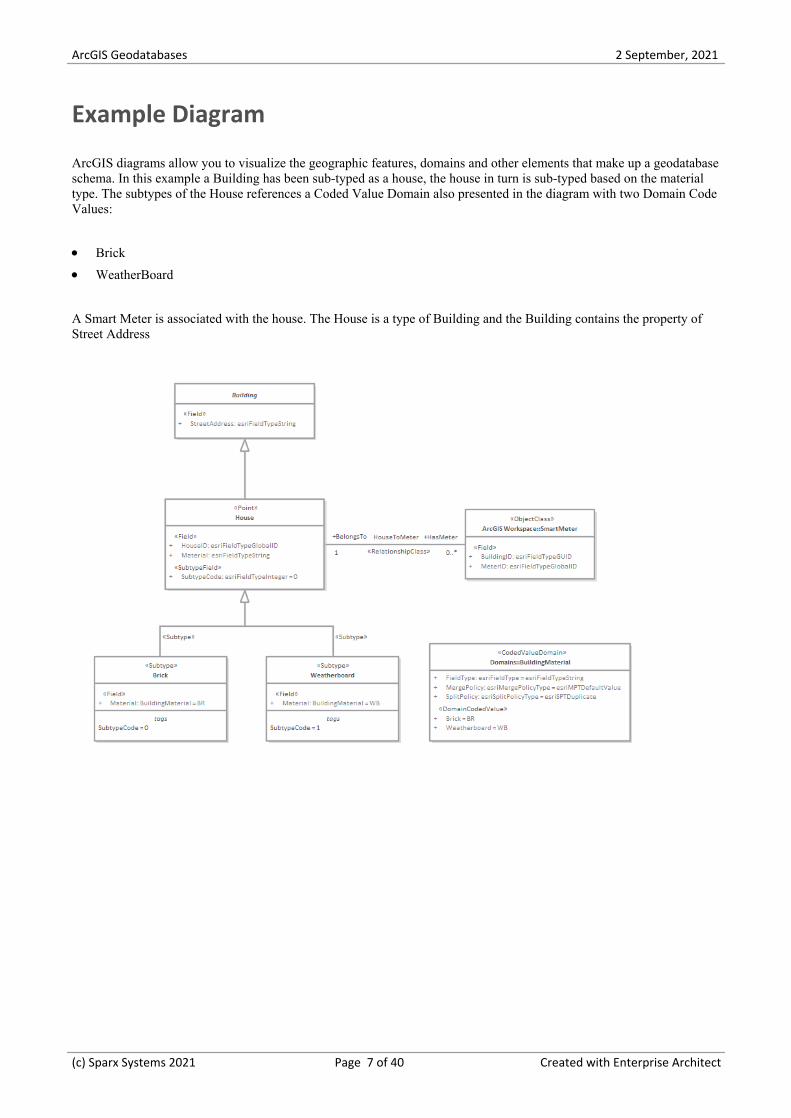
ArcGIS diagrams allow you to visualize the geographic features, domains and other elements that make up a geodatabaseschema. In this example a Building has been sub-typed as a house, the house in turn is sub-typed based on the materialtype. The subtypes of the House references a Coded Value Domain also presented in the diagram with two Domain CodeValues:
Brick·WeatherBoard·
A Smart Meter is associated with the house. The House is a type of Building and the Building contains the property ofStreet Address
(c) Sparx Systems 2021 Page 7 of 40 Created with Enterprise Architect

ArcGIS Geodatabases 2 September, 2021
Modeling with ArcGIS
The MDG Technology for ArcGIS is built in to the Enterprise Architect installer. A key component of the technology isthe UML Profile for ArcGIS.
Access
Ribbon Specialize > Technologies > ArcGIS
Context Menu Right-click on Package | Specialize | ArcGIS
Features
Feature Detail
Profile Support The built-in MDG Technology for ArcGIS provides:
ArcGIS Toolbox pages that map ArcGIS concepts to appropriately stereotyped·UML elements
A Model Pattern that helps you to start designing geodatabases quickly and to·use the required Package structure in Enterprise Architect
Datatypes that are specific to the ArcGIS platform·Quick Linker capabilities that help you make valid connections between·elements
ArcGIS Toolbox Pages The ArcGIS Toolbox contains five core pages:
Domains - for coded value and range domains·Features and Tables - for custom feature types and tables·Network Features - for geometric network and topology Packages·Raster - for raster datasets·Workspace - for ArcGIS workspace and spatial reference information·
Two additional Toolboxes group the objects used specifically in creating GeometricNetwork and Topology diagrams.
Spatial References Enterprise Architect helps you to model Spatial Reference information for yourArcGIS schema, including the selection of predefined coordinate systems andassociated values.
Show/Hide SystemAttribute Fields
The ArcGIS elements provided through the Toolbox pages contain a number ofsystem-assigned attributes that define the «AttributeIndex», «SpatialIndex» and«RequiredField» stereotypes. When you drag an element onto a diagram from theToolbox, these attributes are not visible in the newly-created structure.
If you want to show these system attributes, right-click on the element(s) and selectthe 'Specialize > Technologies > ArcGIS > Show or Hide ArcGIS System Fields'ribbon option. Similarly, if you have exposed the attributes and want to hide them,select the elements and select the menu option again.
(c) Sparx Systems 2021 Page 8 of 40 Created with Enterprise Architect
ArcGIS Geodatabases 2 September, 2021
This option does not operate on attributes or stereotypes you have added to theselected elements, nor on elements that you have not selected.
If you do not select any elements, the option is grayed out.
Notes
The MDG Technology for ArcGIS is available in the Professional, Corporate, Unified and Ultimate Editions of·Enterprise Architect
(c) Sparx Systems 2021 Page 9 of 40 Created with Enterprise Architect

ArcGIS Geodatabases 2 September, 2021
ArcGIS Toolbox Pages
The ArcGIS Toolbox pages provide elements and connectors that you can use to model ArcGIS geodatabase conceptsand relationships. The ArcGIS Toolbox consists of five Core pages:
Domains - for coded value and range domains·Features and Tables - for custom feature types and tables·Network Features - to identify geometric network and topology Packages·Raster - for raster datasets·Workspace - for ArcGIS workspace and spatial reference information·
Two additional Toolboxes group the objects used specifically in creating Geometric Network and Topology diagrams.
Access
On the Diagram Toolbox, click on to display the 'Find Toolbox Item' dialog and specify 'ArcGIS:
Core'·Geometric Network' or·Topology'·
Ribbon Design > Diagram > Toolbox
Keyboard Shortcuts Ctrl+Shift+3
ArcGIS Toolbox Pages
(c) Sparx Systems 2021 Page 10 of 40 Created with Enterprise Architect

ArcGIS Geodatabases 2 September, 2021
Diagram toolbox icons
Toolbox Icon Description
Packages
(c) Sparx Systems 2021 Page 11 of 40 Created with Enterprise Architect
ArcGIS Geodatabases 2 September, 2021
ArcGIS Workspace The geodatabase workspace Package, which holds all the ArcGIS modelingelements.
Export the contents of this Package to produce the Geodatabase XML WorkspaceDocument, which can be imported to Esri ArcCatalog.
ArcGIS Schema View A stereotyped Package that represents a subset of the geodatabase schema definedwithin the ArcGIS Workspace Package. ArcGIS Schema View Packages are usefulif you need to create partial or modular schemas based on your completegeodatabase design. You can create any number of ArcGIS Schema View Packagesunder your ArcGIS Workspace Package.
Add this element to a diagram under your workspace, then create a UMLDependency connector from it to each Package to include in the generated XMLWorkspace Document. For example, you could include only a subset of yourFeature Datasets and Domains, by drawing UML Dependency connectors to theappropriate Packages.
To export your ArcGIS Schema View for use with ArcCatalog, right-click on it andselect the 'Specialize | ArcGIS | Export to ArcGIS Workspace XML' option. Thesystem generates a Workspace XML document containing only the elementsassociated with the ArcGIS Schema View Package.
See the Export Modular ArcGIS Schemas topic.
Feature Dataset A stereotyped Package that holds or organizes Point, Polyline, Polygon orMultipatch elements with the same spatial reference, geometry type and attributefields (that is, Feature Classes).
The Feature Dataset is only created under the ArcGIS Workspace Package; it cannot be created under another Feature Dataset Package. Feature Dataset Packagescan contain other types of sub-Package, however, which can be useful fororganizing large Feature Datasets. When exported to an XML Workspacedocument, elements of any subPackages are included while the subPackagesthemselves are ignored, resulting in a 'flattened' model hierarchy.
Although ArcGIS prevents Tables (ObjectClasses) being defined under FeatureDatasets, Enterprise Architect lets you model Tables under Feature Datasets forconvenience. On export, Tables are placed at the root level to create a valid schema.
Geometric Network An extended UML Package that represents the logical relationships betweenfeatures in a network system – implemented in ArcGIS as a geometric network.
Raster Dataset A stereotyped Package that holds or organizes the raster data (as Raster Bandelements).
Topology An extended UML Package that represents the shared geometry of a set of FeatureClasses from a Feature Dataset.
Elements (in alphabeticalorder)
Abstract Class A standard UML Abstract Class, representing a concept and set of fields, that canbe shared by multiple Feature Classes. Feature Classes that connect to an AbstractClass via an Inheritance relationship gain all of its fields. Since the geodatabasedoes not directly support Abstract Classes, inherited fields are exported into thedefinition of each child Feature Class when generating a schema from the model.
Coded Value Domain An extended UML Class, representing a set of valid values that might apply to anytype of attribute.
(c) Sparx Systems 2021 Page 12 of 40 Created with Enterprise Architect
ArcGIS Geodatabases 2 September, 2021
Concrete Class A standard UML Class that can represent a Feature Class or a Table in ArcGIS,depending on the stereotype setting of its parent Class. If the element has nostereotyped parent Class, it is treated as an ArcGIS Table (Object Class) by default.
MultiPatch An extended UML Class, representing the ArcGIS MultiPatch.
Multipoint An extended UML Class, representing the ArcGIS Multipoint.
Point An extended UML Class, representing the ArcGIS Point.
Polygon An extended UML Class, representing the ArcGIS Polygon.
Polyline An extended UML Class, representing the ArcGIS Polyline.
Range Domain An extended UML Class, representing a valid range of numeric values that mightapply to a numeric type of attribute.
Raster Band An extended UML Class, representing one layer of a matrix of cell values.
Every Raster Dataset contains one or more Raster Bands.
Raster Catalog An extended UML Class, representing a collection of Raster Datasets in thegeodatabase.
Raster StorageDef An extended UML Class, representing the storage properties for a Raster value inthe geodatabase; this information is required when a Raster Dataset Packageelement is created.
Spatial Reference An extended UML Class that defines the spatial reference information of yourschema, such as a coordinate system and XYTolerance.
You can define one or more Spatial Reference elements, which you link to otherArcGIS elements via their Spatial Reference Tagged Value.
Subtype An extended UML Class, holding a subset of the attributes of an element in theFeature Dataset.
Table (Object Class) An extended UML Class, representing a collection of nonspatial data of the sametype or Class.
Relationships (inalphabetical order)
Association A normal UML Association connector.
Connectivity Rule(Edge-Edge)
An extended UML N-ary Association that models the valid relationships betweenedge elements in a Geometric Network.
For an example, see Connectivity Rule Examples.
Connectivity Rule(Edge-Junction)
An extended UML Association that models the valid relationships between edgeand junction elements in a Geometric Network.
For an example, see Connectivity Rule Examples.
Dependency A normal UML Dependency connector.
(c) Sparx Systems 2021 Page 13 of 40 Created with Enterprise Architect
ArcGIS Geodatabases 2 September, 2021
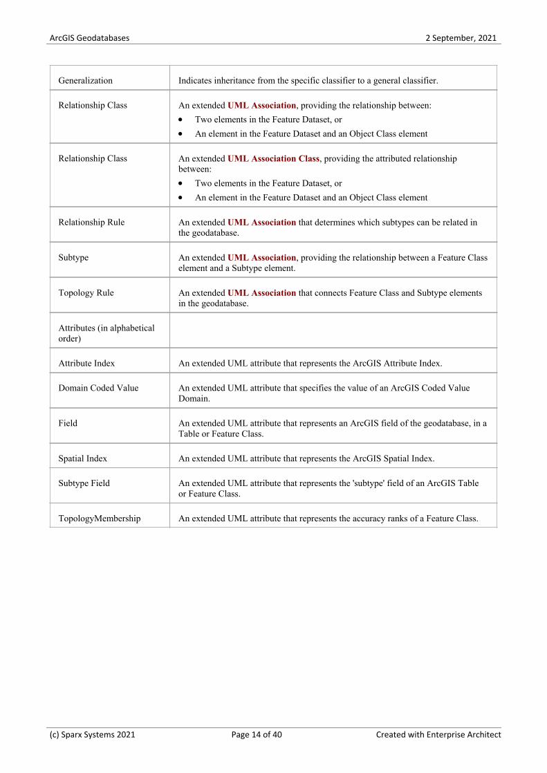
Generalization Indicates inheritance from the specific classifier to a general classifier.
Relationship Class An extended UML Association, providing the relationship between:
Two elements in the Feature Dataset, or·An element in the Feature Dataset and an Object Class element·
Relationship Class An extended UML Association Class, providing the attributed relationshipbetween:
Two elements in the Feature Dataset, or·An element in the Feature Dataset and an Object Class element·
Relationship Rule An extended UML Association that determines which subtypes can be related inthe geodatabase.
Subtype An extended UML Association, providing the relationship between a Feature Classelement and a Subtype element.
Topology Rule An extended UML Association that connects Feature Class and Subtype elementsin the geodatabase.
Attributes (in alphabeticalorder)
Attribute Index An extended UML attribute that represents the ArcGIS Attribute Index.
Domain Coded Value An extended UML attribute that specifies the value of an ArcGIS Coded ValueDomain.
Field An extended UML attribute that represents an ArcGIS field of the geodatabase, in aTable or Feature Class.
Spatial Index An extended UML attribute that represents the ArcGIS Spatial Index.
Subtype Field An extended UML attribute that represents the 'subtype' field of an ArcGIS Tableor Feature Class.
TopologyMembership An extended UML attribute that represents the accuracy ranks of a Feature Class.
(c) Sparx Systems 2021 Page 14 of 40 Created with Enterprise Architect
ArcGIS Geodatabases 2 September, 2021
Connectivity Rule Examples
In an ArcGIS Geometric Network diagram, you can use one or other of the two Connectivity Rule relationships -Edge-Junction or Edge-Edge. These examples illustrate the use of each type.
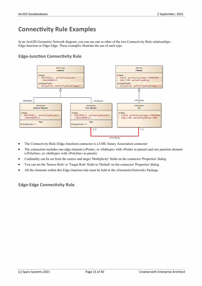
Edge-Junction Connectivity Rule
The Connectivity-Rule (Edge-Junction) connector is a UML binary Association connector·The connection includes one edge element («Point», or «Subtype» with «Point» as parent) and one junction element·(«Polyline», or «Subtype» with «Polyline» as parent)
Cardinality can be set from the source and target 'Multiplicity' fields on the connector 'Properties' dialog·You can set the 'Source Role' or 'Target Role' fields to 'Default' on the connector 'Properties' dialog·All the elements within this Edge-Junction rule must be held in the «GeometricNetwork» Package·
Edge-Edge Connectivity Rule
(c) Sparx Systems 2021 Page 15 of 40 Created with Enterprise Architect
ArcGIS Geodatabases 2 September, 2021
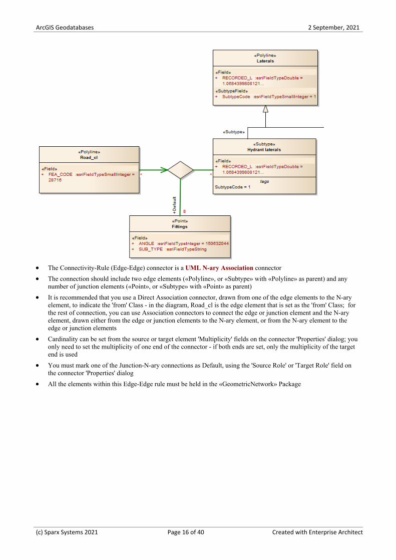
The Connectivity-Rule (Edge-Edge) connector is a UML N-ary Association connector·The connection should include two edge elements («Polyline», or «Subtype» with «Polyline» as parent) and any·number of junction elements («Point», or «Subtype» with «Point» as parent)
It is recommended that you use a Direct Association connector, drawn from one of the edge elements to the N-ary·element, to indicate the 'from' Class - in the diagram, Road_cl is the edge element that is set as the 'from' Class; forthe rest of connection, you can use Association connectors to connect the edge or junction element and the N-aryelement, drawn either from the edge or junction elements to the N-ary element, or from the N-ary element to theedge or junction elements
Cardinality can be set from the source or target element 'Multiplicity' fields on the connector 'Properties' dialog; you·only need to set the multiplicity of one end of the connector - if both ends are set, only the multiplicity of the targetend is used
You must mark one of the Junction-N-ary connections as Default, using the 'Source Role' or 'Target Role' field on·the connector 'Properties' dialog
All the elements within this Edge-Edge rule must be held in the «GeometricNetwork» Package·
(c) Sparx Systems 2021 Page 16 of 40 Created with Enterprise Architect

ArcGIS Geodatabases 2 September, 2021
Topology Example
In geodatabases, topology defines the spatial relationship between geographic features; that is, how Point, Polyline, andPolygon features share coincident geometry. Topology is fundamental to data integrity in a GIS database. In theEnterprise Architect ArcGIS profile, you use a «Topology» Package to model data integrity among the Feature Classes.
Modeling topology in the Enterprise Architect ArcGIS model is simple:
Select a «FeatureDataset» Package in which to create topology relationships.1.
Open the diagram under the «FeatureDataset» Package.2.
From the Diagram Toolbox ArcGIS Network Features page, drag and drop a «Topology» Package icon onto the3.diagram; this creates a Package that will contain all the elements and relationships that are required for topologydefinition.
A Topology defined in Enterprise Architect has these characteristics:
The «Topology» Package cannot be created outside a « FeatureDataset» Package·Within one «FeatureDataset» Package, multiple «Topology» Packages can be created·A Feature Class (Point, Polyline or Polygon) can only participate in one «Topology» Package·A Feature Class cannot participate in both a «Topology» Package and a «GeometricNetwork» Package·
Elements of Topology
Element Description
Name You can define the name for the Topology as the «Topology» Package name.
List of Feature Classes Either:
Create new Feature Classes from the Diagram Toolbox or·Drag existing Feature Classes from the Browser window into the «Topology»·Package
X,Y Cluster Tolerance and
Z Cluster Tolerance
You define the cluster tolerance values using the ClusterTolerance andZClusterTolerance Tagged Values of the «Topology» Package.
Accuracy ranks Accuracy ranks are defined using the Tagged Values of the TopologyMembershipattribute, which you can create using the 'TopologyMembership' icon on the'Topology' page of the Diagram Toolbox.
Add this stereotyped attribute to each Feature Class element and then set a value foreach rank.
The name of the attribute should be the name of the «Topology» Package·You do not need to set the type of the attribute·
Each Feature Class only has one TopologyMembership attribute. If you do not adda TopologyMembership attribute to a Feature Class, the ArcGIS exporter willgenerate a set of default ranking values for you. The values for XYRank and ZRankare between 1 and 50.
Topology Rules Topology Rules are represented by a UML Association connector that has the«TopologyRule» stereotype. You can create the connector using the 'Topology Rule'icon on the 'Topology' page of the Diagram Toolbox.
(c) Sparx Systems 2021 Page 17 of 40 Created with Enterprise Architect
ArcGIS Geodatabases 2 September, 2021
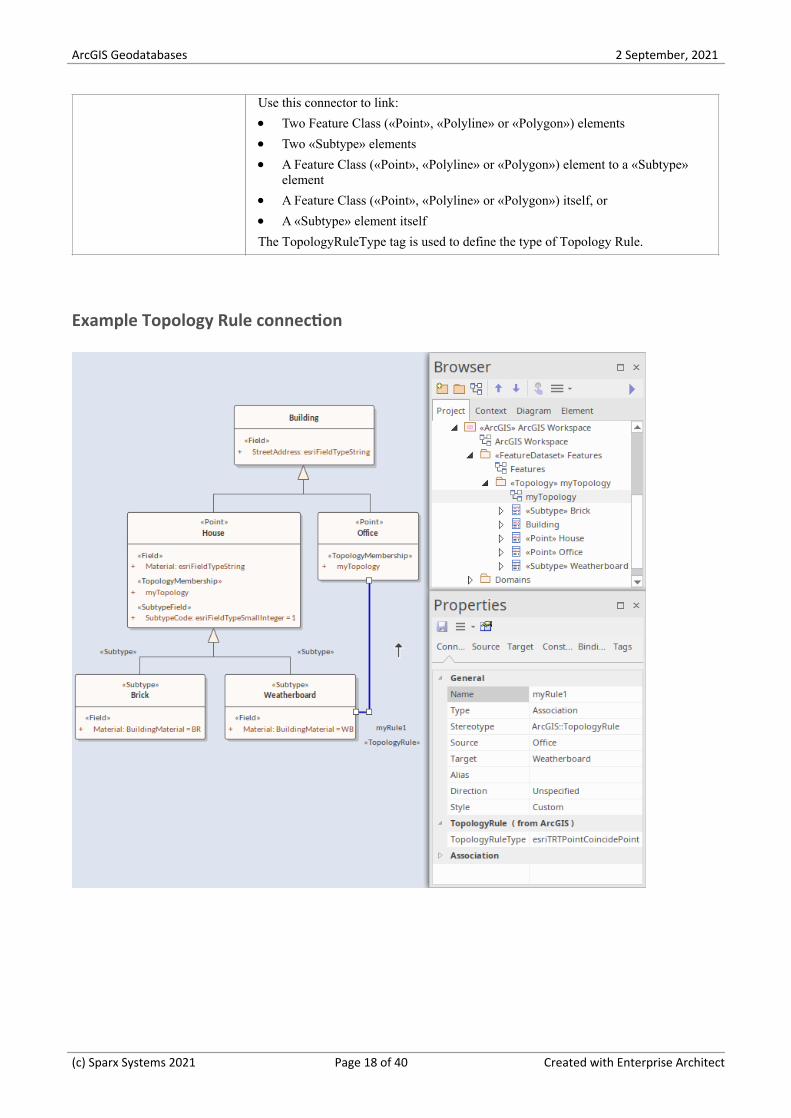
Use this connector to link:
Two Feature Class («Point», «Polyline» or «Polygon») elements·Two «Subtype» elements·A Feature Class («Point», «Polyline» or «Polygon») element to a «Subtype»·element
A Feature Class («Point», «Polyline» or «Polygon») itself, or·A «Subtype» element itself·
The TopologyRuleType tag is used to define the type of Topology Rule.
Example Topology Rule connection
(c) Sparx Systems 2021 Page 18 of 40 Created with Enterprise Architect

ArcGIS Geodatabases 2 September, 2021
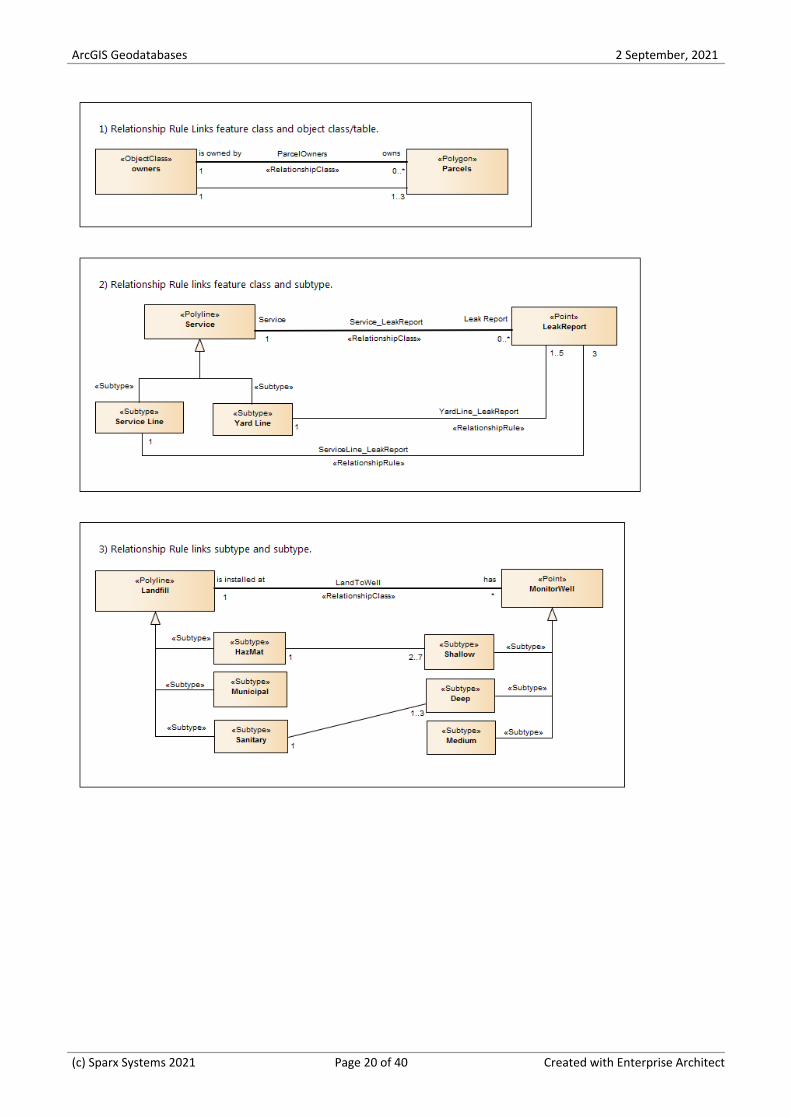
Relationship Rule Example
In ArcGIS modeling, you can use relationship rules to refine the cardinality of a «RelationshipClass» connector betweena source Feature Class or Table and a destination Feature Class or Table; a Relationship Class connector only defines theinitial cardinality, such as one-to-many or many-to-many.
A relationship rule in Enterprise Architect is represented by a «RelationshipRule» connector, a stereotyped UMLAssociation connector, which you can create using the Relationship Rule icon on the 'ArcGIS Core' page of theDiagram Toolbox. You set the cardinality from the source and target 'Multiplicity' fields on the connector 'Properties'dialog.
When creating a «RelationshipRule» connector between two objects, you must have:
An existing «RelationshipClass» connector between the two objects that you want to define the relationship rule for;·if there is no connector, the «RelationshipRule» you create is ignored during ArcGIS schema generation
A cardinality range at each end that is compatible with the cardinality of the parent «RelationshipClass»; for·example, if you define a cardinality of 1-M in a «RelationshipClass» connector, the source end of the«RelationshipRule» connector must be 1, while you can set the target end of the «RelationshipRule» to a specificnumber such as 3 (see the example diagrams in this topic)
Relationship rules can also restrict the type of object in the source Feature Class or Table that can be related to a certainkind of object in the destination Feature Class or Table. For example, if the source Class has no subtype elements, therelationship rule applies to all features. If the source Class has subtype elements and the «RelationshipRule» is linked toone of the subtype elements, this means only the associated subtype element is related to the «RelationshipRule». Thesame restriction is also applied to the destination Feature Class or Table.
Examples
This diagram provides three examples of possible «RelationshipRule» connections in an ArcGIS model. A custom LineThickness has been applied to highlight the Relationship Class connectors, and the «RelationshipRule» stereotype labelhas been hidden where appropriate:
(c) Sparx Systems 2021 Page 19 of 40 Created with Enterprise Architect
ArcGIS Geodatabases 2 September, 2021
(c) Sparx Systems 2021 Page 20 of 40 Created with Enterprise Architect
ArcGIS Geodatabases 2 September, 2021
Setting ArcGIS Coordinate Systems
ArcGIS Feature Classes and Feature Datasets use spatial references, which consist of a coordinate system and associatedvalues such as XY resolution and various tolerance values.
You can capture spatial reference properties using a Class stereotyped as «SpatialReference», which is available from theArcGIS Toolbox pages. The ArcGIS model Pattern includes a Package named Spatial References, as a placeholder forcreating such elements.
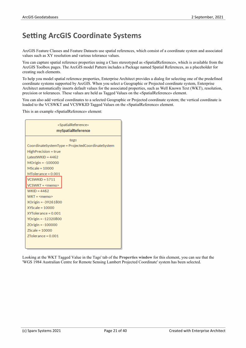
To help you model spatial reference properties, Enterprise Architect provides a dialog for selecting one of the predefinedcoordinate systems supported by ArcGIS. When you select a Geographic or Projected coordinate system, EnterpriseArchitect automatically inserts default values for the associated properties, such as Well Known Text (WKT), resolution,precision or tolerances. These values are held as Tagged Values on the «SpatialReference» element.
You can also add vertical coordinates to a selected Geographic or Projected coordinate system; the vertical coordinate isloaded to the VCSWKT and VCSWKID Tagged Values on the «SpatialReference» element.
This is an example «SpatialReference» element:
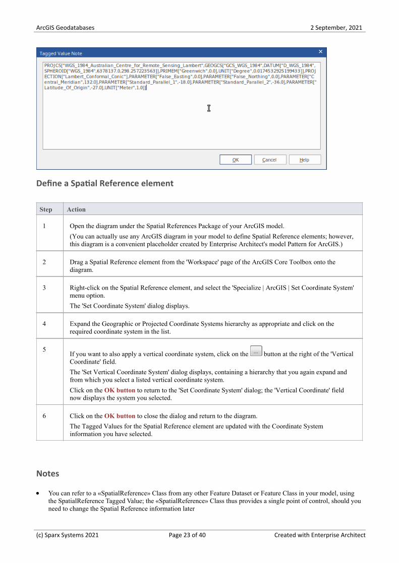
Looking at the WKT Tagged Value in the Tags' tab of the Properties window for this element, you can see that the'WGS 1984 Australian Centre for Remote Sensing Lambert Projected Coordinate' system has been selected.
(c) Sparx Systems 2021 Page 21 of 40 Created with Enterprise Architect
ArcGIS Geodatabases 2 September, 2021
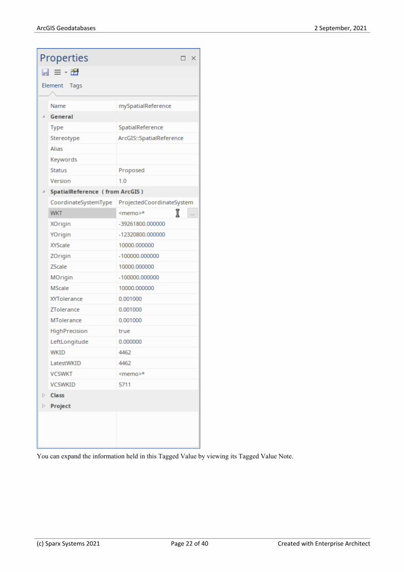
You can expand the information held in this Tagged Value by viewing its Tagged Value Note.
(c) Sparx Systems 2021 Page 22 of 40 Created with Enterprise Architect
ArcGIS Geodatabases 2 September, 2021
Define a Spatial Reference element
Step Action
1 Open the diagram under the Spatial References Package of your ArcGIS model.
(You can actually use any ArcGIS diagram in your model to define Spatial Reference elements; however,this diagram is a convenient placeholder created by Enterprise Architect's model Pattern for ArcGIS.)
2 Drag a Spatial Reference element from the 'Workspace' page of the ArcGIS Core Toolbox onto thediagram.
3 Right-click on the Spatial Reference element, and select the 'Specialize | ArcGIS | Set Coordinate System'menu option.
The 'Set Coordinate System' dialog displays.
4 Expand the Geographic or Projected Coordinate Systems hierarchy as appropriate and click on therequired coordinate system in the list.
5If you want to also apply a vertical coordinate system, click on the button at the right of the 'VerticalCoordinate' field.
The 'Set Vertical Coordinate System' dialog displays, containing a hierarchy that you again expand andfrom which you select a listed vertical coordinate system.
Click on the OK button to return to the 'Set Coordinate System' dialog; the 'Vertical Coordinate' fieldnow displays the system you selected.
6 Click on the OK button to close the dialog and return to the diagram.
The Tagged Values for the Spatial Reference element are updated with the Coordinate Systeminformation you have selected.
Notes
You can refer to a «SpatialReference» Class from any other Feature Dataset or Feature Class in your model, using·the SpatialReference Tagged Value; the «SpatialReference» Class thus provides a single point of control, should youneed to change the Spatial Reference information later
(c) Sparx Systems 2021 Page 23 of 40 Created with Enterprise Architect
ArcGIS Geodatabases 2 September, 2021
If a Feature Class element references a «SpatialReference» Class that contains a vertical coordinate, set the HasZ·Tagged Value on that Feature Class element to true if you want this Feature Class element to store three-dimensionaldata
If you do not refer to a «SpatialReference» Class from any Feature Dataset or Feature Class in your ArcGIS model,·the system will generate an XML schema with the Unknown Spatial Reference type for these elements
(c) Sparx Systems 2021 Page 24 of 40 Created with Enterprise Architect
ArcGIS Geodatabases 2 September, 2021
Applying ArcGIS Stereotypes to Abstract Classes
Using the Enterprise Architect UML Profile for ArcGIS, you can specify a geometry stereotype on the Feature Classes inyour geodatabase schema. Geometry stereotypes include «Point», «Polyline», «Polygon» and «Multipoint», amongothers. The ArcGIS Toolbox provides convenient icons for each geometry so that you can drag and drop stereotypedClasses into your geodatabase design model that are immediately ready to export. These Classes are referred to asconcrete Classes; since their UML property, IsAbstract, has a value of False, they will be implemented directly in thegeodatabase schema.
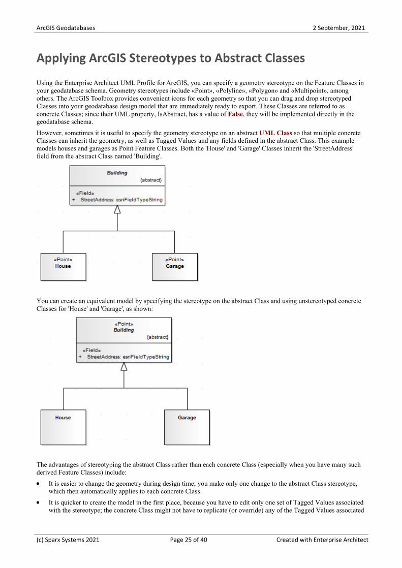
However, sometimes it is useful to specify the geometry stereotype on an abstract UML Class so that multiple concreteClasses can inherit the geometry, as well as Tagged Values and any fields defined in the abstract Class. This examplemodels houses and garages as Point Feature Classes. Both the 'House' and 'Garage' Classes inherit the 'StreetAddress'field from the abstract Class named 'Building'.
You can create an equivalent model by specifying the stereotype on the abstract Class and using unstereotyped concreteClasses for 'House' and 'Garage', as shown:
The advantages of stereotyping the abstract Class rather than each concrete Class (especially when you have many suchderived Feature Classes) include:
It is easier to change the geometry during design time; you make only one change to the abstract Class stereotype,·which then automatically applies to each concrete Class
It is quicker to create the model in the first place, because you have to edit only one set of Tagged Values associated·with the stereotype; the concrete Class might not have to replicate (or override) any of the Tagged Values associated
(c) Sparx Systems 2021 Page 25 of 40 Created with Enterprise Architect
ArcGIS Geodatabases 2 September, 2021
with its inherited geometry stereotype
For the same reason, the overall model is smaller and simpler·
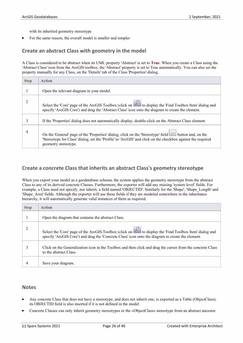
Create an abstract Class with geometry in the model
A Class is considered to be abstract when its UML property 'Abstract' is set to True. When you create a Class using the'Abstract Class' icon from the ArcGIS toolbox, the 'Abstract' property is set to True automatically. You can also set theproperty manually for any Class, on the 'Details' tab of the Class 'Properties' dialog.
Step Action
1 Open the relevant diagram in your model.
2Select the 'Core' page of the ArcGIS Toolbox (click on to display the 'Find Toolbox Item' dialog andspecify 'ArcGIS Core') and drag the 'Abstract Class' icon onto the diagram to create the element.
3 If the 'Properties' dialog does not automatically display, double-click on the Abstract Class element.
4On the 'General' page of the 'Properties' dialog, click on the 'Stereotype' field button and, on the'Stereotype for Class' dialog, set the 'Profile' to 'ArcGIS' and click on the checkbox against the requiredgeometry stereotype.
Create a concrete Class that inherits an abstract Class's geometry stereotype
When you export your model as a geodatabase schema, the system applies the geometry stereotype from the abstractClass to any of its derived concrete Classes. Furthermore, the exporter will add any missing 'system level' fields. Forexample, a Class need not specify, nor inherit, a field named 'OBJECTID'. Similarly for the 'Shape', 'Shape_Length' and'Shape_Area' fields. Although the exporter will use these fields if they are modeled somewhere in the inheritancehierarchy, it will automatically generate valid instances of them as required.
Step Action
1 Open the diagram that contains the abstract Class.
2Select the 'Core' page of the ArcGIS Toolbox (click on to display the 'Find Toolbox Item' dialog andspecify 'ArcGIS Core') and drag the 'Concrete Class' icon onto the diagram to create the element.
3 Click on the Generalization icon in the Toolbox and then click and drag the cursor from the concrete Classto the abstract Class.
4 Save your diagram.
Notes
Any concrete Class that does not have a stereotype, and does not inherit one, is exported as a Table (ObjectClass);·its OBJECTID field is also inserted if it is not defined in the model
Concrete Classes can only inherit geometry stereotypes or the «ObjectClass» stereotype from an abstract ancestor·
(c) Sparx Systems 2021 Page 26 of 40 Created with Enterprise Architect
ArcGIS Geodatabases 2 September, 2021
Class; currently, Enterprise Architect does not support stereotype inheritance from other concrete Classes
In addition to inheriting the stereotype, concrete Classes also inherit fields from ancestor abstract Classes·You can inherit the stereotype from an abstract Class at any level in inheritance hierarchy; for example, the abstract·Class that specifies the geometry can be the grandparent of the concrete Class, rather than the parent Class
Multiple shapes for a single Feature Class are not supported by ArcGIS, nor by Enterprise Architect's ArcGIS·profile; therefore, it would be a modeling error if a concrete Class inherited from more than onegeometry-stereotyped abstract Class
If you specify a given tag on a concrete Class that is already present in one of its parent abstract Classes, the·concrete Class has precedence and its Tagged Value will be exported to the schema
Enterprise Architect does not require you to show the Object and Feature Esri Classes on a diagram, nor even·include them in your model, because the system implicitly applies their characteristics when you apply a geometryor ObjectClass stereotype to a Class
It is not, however, an error to include the Object and Feature Esri Classes and model Generalization links to them,·even though they are typically not marked as abstract
(c) Sparx Systems 2021 Page 27 of 40 Created with Enterprise Architect
ArcGIS Geodatabases 2 September, 2021
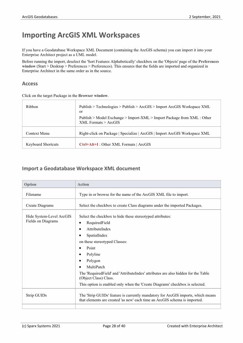
Importing ArcGIS XML Workspaces
If you have a Geodatabase Workspace XML Document (containing the ArcGIS schema) you can import it into yourEnterprise Architect project as a UML model.
Before running the import, deselect the 'Sort Features Alphabetically' checkbox on the 'Objects' page of the Preferenceswindow (Start > Desktop > Preferences > Preferences). This ensures that the fields are imported and organized inEnterprise Architect in the same order as in the source.
Access
Click on the target Package in the Browser window.
Ribbon Publish > Technologies > Publish > ArcGIS > Import ArcGIS Workspace XMLor
Publish > Model Exchange > Import-XML > Import Package from XML : OtherXML Formats > ArcGIS
Context Menu Right-click on Package | Specialize | ArcGIS | Import ArcGIS Workspace XML
Keyboard Shortcuts Ctrl+Alt+I : Other XML Formats | ArcGIS
Import a Geodatabase Workspace XML document
Option Action
Filename Type in or browse for the name of the ArcGIS XML file to import.
Create Diagrams Select the checkbox to create Class diagrams under the imported Packages.
Hide System-Level ArcGISFields on Diagrams
Select the checkbox to hide these stereotyped attributes:
RequiredField·AttributeIndex·SpatialIndex·
on these stereotyped Classes:
Point·Polyline·Polygon·MultiPatch·
The 'RequiredField' and 'AttributeIndex' attributes are also hidden for the Table(Object Class) Class.
This option is enabled only when the 'Create Diagrams' checkbox is selected.
Strip GUIDs The 'Strip GUIDs' feature is currently mandatory for ArcGIS imports, which meansthat elements are created 'as new' each time an ArcGIS schema is imported.
(c) Sparx Systems 2021 Page 28 of 40 Created with Enterprise Architect
ArcGIS Geodatabases 2 September, 2021
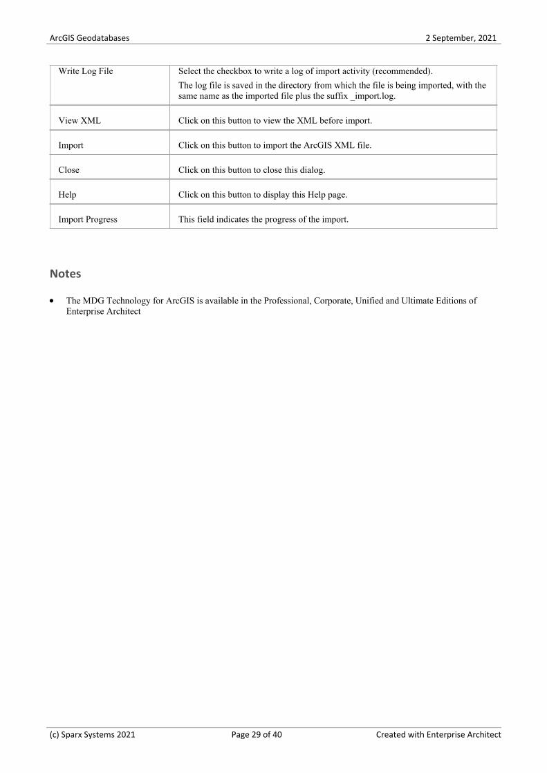
Write Log File Select the checkbox to write a log of import activity (recommended).
The log file is saved in the directory from which the file is being imported, with thesame name as the imported file plus the suffix _import.log.
View XML Click on this button to view the XML before import.
Import Click on this button to import the ArcGIS XML file.
Close Click on this button to close this dialog.
Help Click on this button to display this Help page.
Import Progress This field indicates the progress of the import.
Notes
The MDG Technology for ArcGIS is available in the Professional, Corporate, Unified and Ultimate Editions of·Enterprise Architect
(c) Sparx Systems 2021 Page 29 of 40 Created with Enterprise Architect
ArcGIS Geodatabases 2 September, 2021
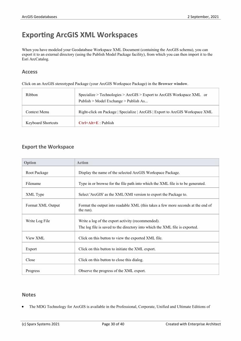
Exporting ArcGIS XML Workspaces
When you have modeled your Geodatabase Workspace XML Document (containing the ArcGIS schema), you canexport it to an external directory (using the Publish Model Package facility), from which you can then import it to theEsri ArcCatalog.
Access
Click on an ArcGIS stereotyped Package (your ArcGIS Workspace Package) in the Browser window.
Ribbon Specialize > Technologies > ArcGIS > Export to ArcGIS Workspace XML or
Publish > Model Exchange > Publish As...
Context Menu Right-click on Package | Specialize | ArcGIS | Export to ArcGIS Workspace XML
Keyboard Shortcuts Ctrl+Alt+E : Publish
Export the Workspace
Option Action
Root Package Display the name of the selected ArcGIS Workspace Package.
Filename Type in or browse for the file path into which the XML file is to be generated.
XML Type Select 'ArcGIS' as the XML/XMI version to export the Package to.
Format XML Output Format the output into readable XML (this takes a few more seconds at the end ofthe run).
Write Log File Write a log of the export activity (recommended).
The log file is saved to the directory into which the XML file is exported.
View XML Click on this button to view the exported XML file.
Export Click on this button to initiate the XML export.
Close Click on this button to close this dialog.
Progress Observe the progress of the XML export.
Notes
The MDG Technology for ArcGIS is available in the Professional, Corporate, Unified and Ultimate Editions of·
(c) Sparx Systems 2021 Page 30 of 40 Created with Enterprise Architect
ArcGIS Geodatabases 2 September, 2021
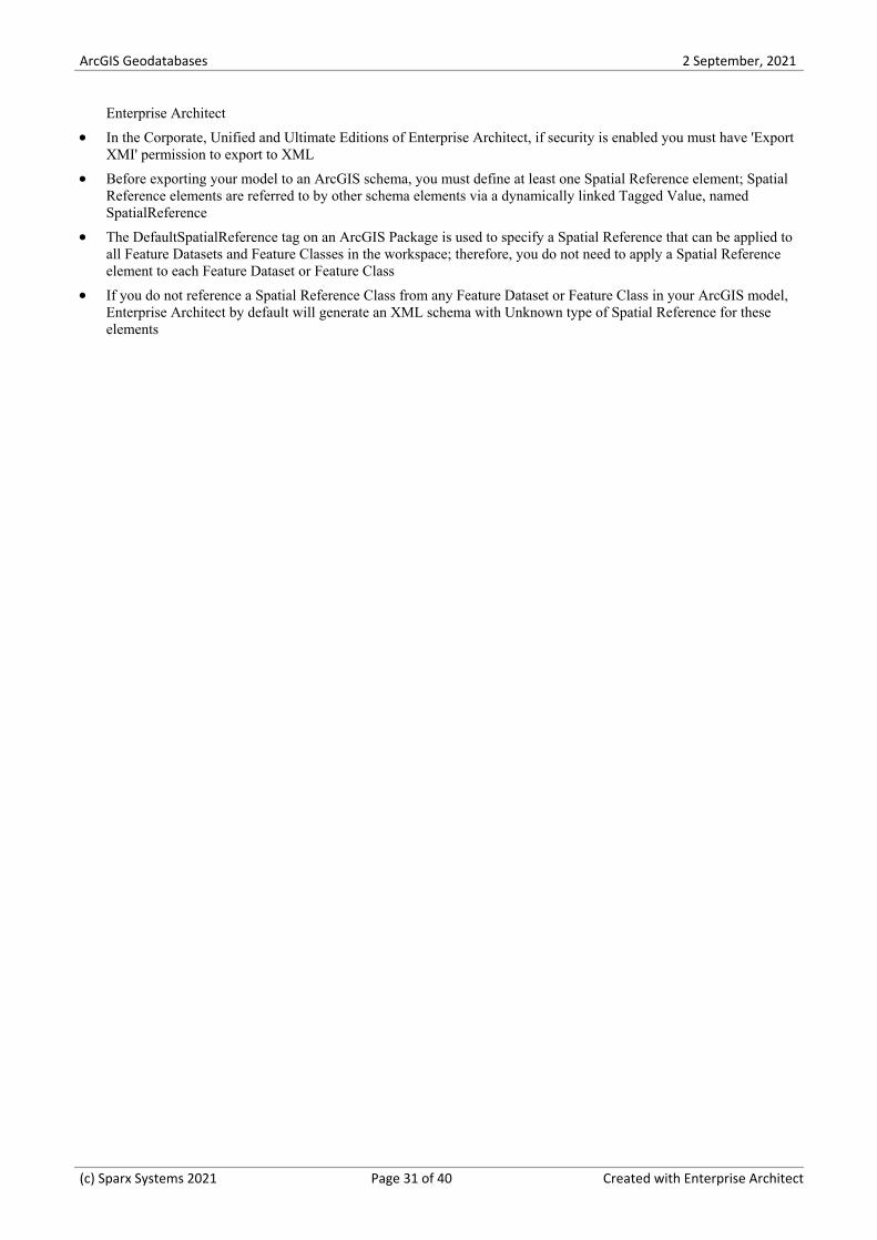
Enterprise Architect
In the Corporate, Unified and Ultimate Editions of Enterprise Architect, if security is enabled you must have 'Export·XMI' permission to export to XML
Before exporting your model to an ArcGIS schema, you must define at least one Spatial Reference element; Spatial·Reference elements are referred to by other schema elements via a dynamically linked Tagged Value, namedSpatialReference
The DefaultSpatialReference tag on an ArcGIS Package is used to specify a Spatial Reference that can be applied to·all Feature Datasets and Feature Classes in the workspace; therefore, you do not need to apply a Spatial Referenceelement to each Feature Dataset or Feature Class
If you do not reference a Spatial Reference Class from any Feature Dataset or Feature Class in your ArcGIS model,·Enterprise Architect by default will generate an XML schema with Unknown type of Spatial Reference for theseelements
(c) Sparx Systems 2021 Page 31 of 40 Created with Enterprise Architect
ArcGIS Geodatabases 2 September, 2021
Export Modular ArcGIS Schemas
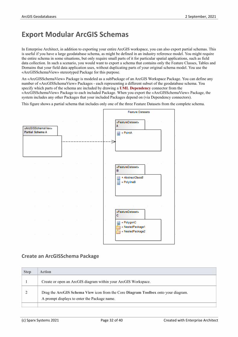
In Enterprise Architect, in addition to exporting your entire ArcGIS workspace, you can also export partial schemas. Thisis useful if you have a large geodatabase schema, as might be defined in an industry reference model. You might requirethe entire schema in some situations, but only require small parts of it for particular spatial applications, such as fielddata collection. In such a scenario, you would want to export a schema that contains only the Feature Classes, Tables andDomains that your field data application uses, without duplicating parts of your original schema model. You use the«ArcGISSchemaView» stereotyped Package for this purpose.
An «ArcGISSchemaView» Package is modeled as a subPackage of an ArcGIS Workspace Package. You can define anynumber of «ArcGISSchemaView» Packages - each representing a different subset of the geodatabase schema. Youspecify which parts of the schema are included by drawing a UML Dependency connector from the«ArcGISSchemaView» Package to each included Package. When you export the «ArcGISSchemaView» Package, thesystem includes any other Packages that your included Packages depend on (via Dependency connectors).
This figure shows a partial schema that includes only one of the three Feature Datasets from the complete schema.
Create an ArcGISSchema Package
Step Action
1 Create or open an ArcGIS diagram within your ArcGIS Workspace.
2 Drag the ArcGIS Schema View icon from the Core Diagram Toolbox onto your diagram.
A prompt displays to enter the Package name.
(c) Sparx Systems 2021 Page 32 of 40 Created with Enterprise Architect
ArcGIS Geodatabases 2 September, 2021
3 Type in a meaningful Package name and click on the OK button.
4 Drag onto the diagram any other Packages that you want to include in the exported schema.
(You could achieve the same result using the child diagram of the «ArcGISSchema View» Package todraw the included Packages).
5 Draw a Dependency connector from the «ArcGISSchema View» Package to each of the other Packages.
Notes
Defining the Dependency relationships on a diagram is convenient, but not necessary; as long as the dependencies·are defined in the model – irrespective of whether they exist on a diagram – the ArcGIS schema exporter will usethem
You can arrange your dependency diagrams in whatever part of the ArcGIS Workspace seems appropriate – the·diagrams can reside under the «ArcGISSchema View » Package itself or under any other element within the ArcGISWorkspace
Export an ArcGIS Schema View for use with ArcCatalog
Step Action
1 Select the ArcGIS Schema View Package in a diagram or in the Browser window.
2 Right-click and select the 'Specialize | ArcGIS | Export to ArcGIS Workspace XML' menu option.
3 Identify the target file and click on the Export button.
The system generates a Workspace XML document containing only the elements associated with theArcGIS Schema View Package.
Which related elements are included when you export an ArcGIS Schema ViewPackage?
These rules apply when you export an ArcGIS Schema View Package:
Dependencies are modeled using the UML Dependency connector·All elements of a Package that the ArcGIS Schema View depends on (directly or indirectly) are included in the·generated schema
All fields inherited from Abstract Classes by included elements are exported, regardless of the Package in which the·Abstract Classes reside
All Coded Value Domain elements to which included elements refer are exported, regardless of the Package in·which the Coded Value Domain elements reside
If an ArcGIS Schema View Package depends on one or more subPackages of a Feature Dataset Package, the Feature·Dataset is exported with only those elements contained in the linked subPackages - no Feature Classes, Domains andTables that are directly contained in the FeatureDataset Package are exported, because of the Dependency to one ofits subPackages; therefore, if you want to export the entire Feature Dataset you must use a Dependency to the
(c) Sparx Systems 2021 Page 33 of 40 Created with Enterprise Architect
ArcGIS Geodatabases 2 September, 2021
Feature Dataset Package itself
If a field of an included element refers to a Coded Value Domain element, that Coded Value Domain element is·exported, irrespective of whether the ArcGIS Schema View Package has an explicit dependency on the Coded ValueDomain element's Package
If an included element has a Relationship Class connector to another element X AND element X is not already·included by the ArcGIS Schema View, neither element X nor the Relationship Class connector are exported; the logfile will hold a list of names of the Relationship Class connectors that, for this reason, are not exported
Examples of modeling partial schemas
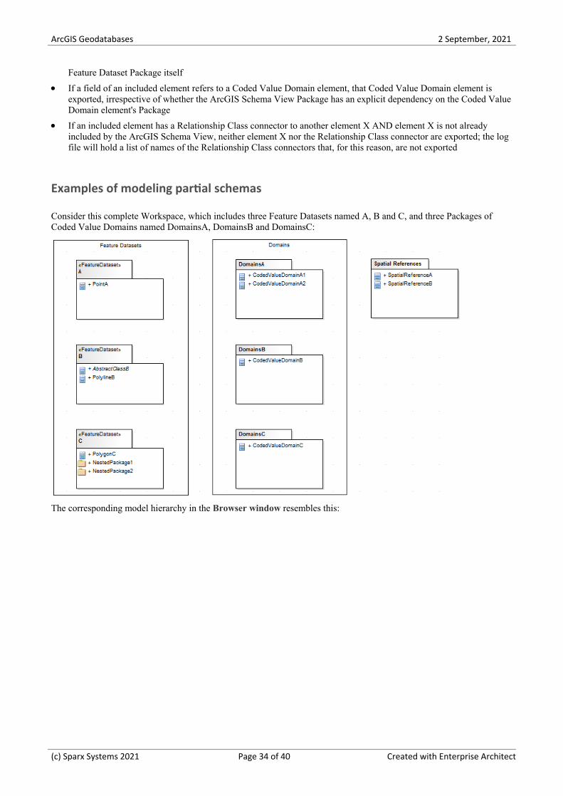
Consider this complete Workspace, which includes three Feature Datasets named A, B and C, and three Packages ofCoded Value Domains named DomainsA, DomainsB and DomainsC:
The corresponding model hierarchy in the Browser window resembles this:
(c) Sparx Systems 2021 Page 34 of 40 Created with Enterprise Architect

ArcGIS Geodatabases 2 September, 2021
If you want to export only Feature Dataset A and its required elements, you can model the Schema as a partial schemathat includes a single Feature Dataset, as shown:
(This diagram is equivalent to the first diagram provided at the start of the topic.) Assuming that Point A depends on noother elements, the resulting schema would include only FeatureDataset A with its Feature Class, Point A.
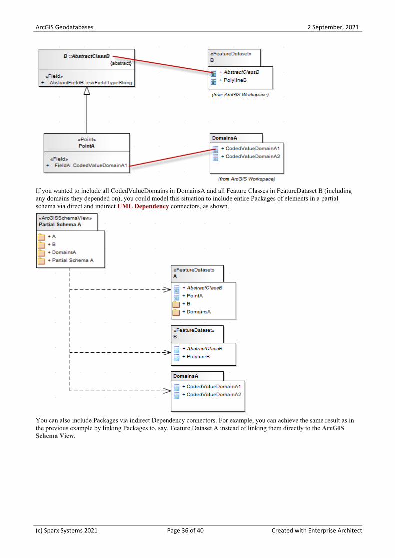
Now assume that Point A inherits from the Abstract Class AbstractClassB (defined in FeatureDataset Package B) andthat one of A's fields has type CodedValueDomainA1 defined in the DomainsA Package (as in the next model diagram).Now, the same Partial Schema model would result in an exported schema that included the fields of AbstractClassB andCodedValueDomainA1, even though Partial Schema A does not explicitly depend on Package B or Package DomainsA,because partial schemas automatically include elements that are related by inheritance or are referred to by field types.The exporter thus helps you to generate valid ArcGIS schemas by including such required elements.
(c) Sparx Systems 2021 Page 35 of 40 Created with Enterprise Architect
ArcGIS Geodatabases 2 September, 2021
If you wanted to include all CodedValueDomains in DomainsA and all Feature Classes in FeatureDataset B (includingany domains they depended on), you could model this situation to include entire Packages of elements in a partialschema via direct and indirect UML Dependency connectors, as shown.
You can also include Packages via indirect Dependency connectors. For example, you can achieve the same result as inthe previous example by linking Packages to, say, Feature Dataset A instead of linking them directly to the ArcGISSchema View.
(c) Sparx Systems 2021 Page 36 of 40 Created with Enterprise Architect
ArcGIS Geodatabases 2 September, 2021
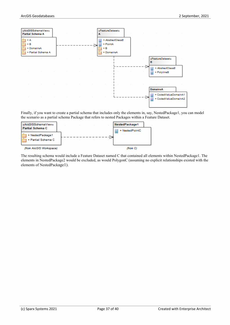
Finally, if you want to create a partial schema that includes only the elements in, say, NestedPackage1, you can modelthe scenario as a partial schema Package that refers to nested Packages within a Feature Dataset.
The resulting schema would include a Feature Dataset named C that contained all elements within NestedPackage1. Theelements in NestedPackage2 would be excluded, as would PolygonC (assuming no explicit relationships existed with theelements of NestedPackage1).
(c) Sparx Systems 2021 Page 37 of 40 Created with Enterprise Architect
ArcGIS Geodatabases 2 September, 2021
Validate ArcGIS Workspaces
When you have developed or imported an ArcGIS model, you can validate it against a set of rules in a system-providedArcGIS validation table.
Access
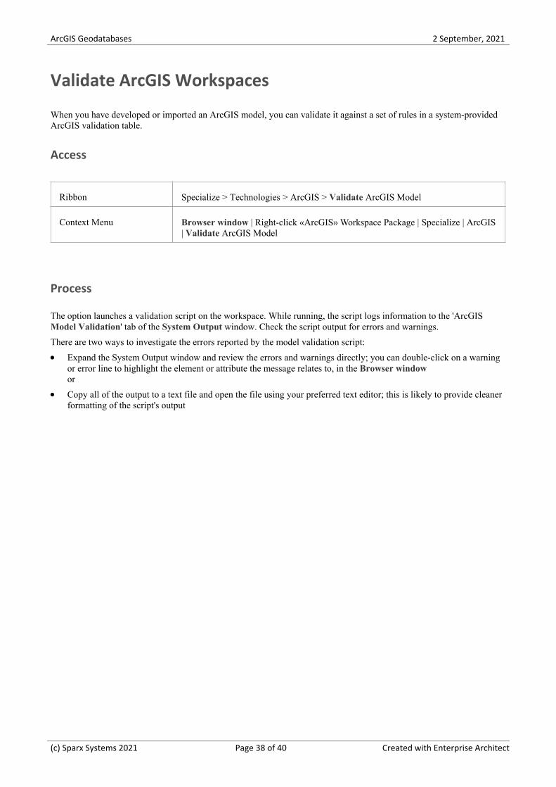
Ribbon Specialize > Technologies > ArcGIS > Validate ArcGIS Model
Context Menu Browser window | Right-click «ArcGIS» Workspace Package | Specialize | ArcGIS| Validate ArcGIS Model
Process
The option launches a validation script on the workspace. While running, the script logs information to the 'ArcGISModel Validation' tab of the System Output window. Check the script output for errors and warnings.
There are two ways to investigate the errors reported by the model validation script:
Expand the System Output window and review the errors and warnings directly; you can double-click on a warning·or error line to highlight the element or attribute the message relates to, in the Browser windowor
Copy all of the output to a text file and open the file using your preferred text editor; this is likely to provide cleaner·formatting of the script's output
(c) Sparx Systems 2021 Page 38 of 40 Created with Enterprise Architect
ArcGIS Geodatabases 2 September, 2021
More Information
Edition Information
The MDG Technology for ArcGIS is available in the Professional, Corporate, Unified and Ultimate Editions of·Enterprise Architect
Notice of Acknowledgement:
Support for modeling ArcGIS databases in Enterprise Architect was developed in collaboration with the CommonwealthScientific and Industrial Research Organization (CSIRO), who defined mappings between UML 2 and ArcGIS concepts,and prototyped an automated import and export capability for ArcGIS geodatabase schemas represented in UML.
(c) Sparx Systems 2021 Page 39 of 40 Created with Enterprise Architect
ArcGIS Geodatabases 2 September, 2021
(c) Sparx Systems 2021 Page 40 of 40 Created with Enterprise Architect