arch dam and skewback and dam abutment rock mass … · 2017-01-20 · according to the arch dam...
TRANSCRIPT

Procedia Environmental Sciences 12 ( 2012 ) 561 – 567
1878-0296 © 2011 Published by Elsevier B.V. Selection and/or peer-review under responsibility of National University of Singapore.doi: 10.1016/j.proenv.2012.01.318
2011 International Conference on Environmental Science and Engineering
(ICESE 2011)
Arch Dam and Skewback and Dam Abutment Rock Mass Deformation under Seepage Field and Stress Field Coupling
Huan Ling Wanga,Miao Heb
aCollege of Harbor, Coastal and Offshore Engineering,Hohai University
Nanjing, China 210098,[email protected] bJiangsu transportation research institute,Nanjing, China 211112,[email protected]
Abstract
Seepage and stress field interaction is one of important characteristics of rock mass which can not be ignored. Rock mass seepage and stress field coupling has become one of the hot and difficult problems in rock mechanics, and also a scientific problem in practical engineering which need to solve. In this paper, based on a Water Resources and Hydropower Engineering to establish the geotechnical model, according to the discrete fracture network, the equivalent continuous medium mathematical model of seepage and stress field coupling was constructed, the efficient numerical methods and computer program for solving seepage and stress field coupling were developed, the rock mass deformation and failure under seepage and stress coupling were conducted the quantitative analysis, which provide a new technical ways and means for scientific predicting the stability of Water Resources and Hydropower Engineering. The computation results show that the seepage and stress field coupling effect should be considered when analyzing rock mass deformation. © 2011 Published by Elsevier Ltd. Selection and/or peer-review under responsibility of [name organizer] Keywords:rock hydraulics, seepage field and stress field coupling, medium model, deformation analysis.
1.Introduction
Fractured rock mass is a complex medium, which frequently encountered in hydraulic and mining and others rock engineering. Seepage field and stress field interaction is one of important characteristics
This work is partially supported by NSFC Grant # 51009052 and Three Gorge Research Center for Geo-hazard, Ministry of Education Grant # TGRC201026 and Fundamental Research Funds for the Central Universities Grant # 2010B02514.
Available online at www.sciencedirect.com
© 2011 Published by Elsevier B.V. Selection and/or peer-review under responsibility of National University of Singapore.Open access under CC BY-NC-ND license.
Open access under CC BY-NC-ND license.
562 Huan Ling Wang and Miao He / Procedia Environmental Sciences 12 ( 2012 ) 561 – 567
of rock which can not be ignored. If it is not fully take into account the seepage field and stress field coupling problem, we can not take effective treatment and preventive measures to prevent the occurrence of major projects accident in the operation and management of water resources and hydropower engineering. The most typical example: France Malpasset arch dam had accident in 1959[1, 2], and the left bank of Italy Vajiont arch dam occurred large landslide in 1963[3]. These two major disasters occurred in 1960s, rock mechanics, especially the rock hydraulics was still at the embryonic stage in that era, the researchers have not recognized the key of rock mass seepage and stress coupling. Rock mass seepage and stress coupling has become one of the hot and difficult problems in rock mechanics with the research and development of series of large water conservancy and hydropower engineering [4, 5].
The research on the rock mass seepage and stress coupling is along with the development of rock engineering practice gradually developed, which has made a lot of theoretical and practical results. The coupled mechanism main includes two aspects: At first, the impact of rock deformation under stress on the seepage, which including the flow pattern of seepage field and water head field [6-12]; Secondly, the mechanical response of rock mass skeleton under seepage, which including the rock mass deformation, damage and stability et al [13]. The former research on the coupled mechanism focuses on the seepage mechanics and the latter one emphasis on solid mechanics. The mathematical model can be divided into three types, but each has its advantages and disadvantages and the limits of usage. Currently, the studies on large-scale and certainty have become more and more attention with the rising of large rock engineering of DECOVALEX (Development of Coupled models and their Validation against Experiments), at the same time, the coupling mechanism has been studied in details. Therefore, higher level of equivalent continuum model is becoming a hot and frontier issue [14-16], and also many new equivalent continuous method has been emerged, which include: (1)The equivalent continuum model method on the basis of discrete fracture network model; (2)Homogenization theory based on the asymptotic expansions; (3)Self-consistent method;(4) Micromechanics methods et al. These research results can be used as reference of hydropower Project rock mass deformation analysis under seepage and stress coupling.
2.Mathematical model and program development
The discrete fracture network method was proposed to determine the porous medium equivalence by Long et al (1982). Since then, many scholars have adopted this method to analyze the rock hydraulic problems [17, 18].Rock mass seepage equations derived by the following equations. According to mass conservation law, Continuity equation of ground water is as follows:
i
i
v nx t
i = 1 , 2 , 3 ( 1 )
Where is fluid density and vi denotes Darcy velocity, n is porosity and t denotes time. According to the Hook law, right side of formula (1) can be decomposed as follows:
sh hn n n n S
t t t t t (2)
Where is the compression coefficient of groundwater, is the compression coefficient of rock mass medium , Ss is storage coefficient, h denotes total water head, is fluid bulk density.
Groundwater flow partial differential equation is as follows:

563 Huan Ling Wang and Miao He / Procedia Environmental Sciences 12 ( 2012 ) 561 – 567
zhyhxh
kkkkkkkkk
vvv
v
zzyzxz
yzyyyx
zxyxxx
z
y
x
///
(3)
Where kxx, kxy... kzz are nine hydraulic conductivity coefficient; x, y, z are Cartesian coordinates. Set the permeability coefficient of groundwater of main permeability direction is kx, ky, kz, when the
axis chosen are in the same direction with the groundwater permeability direction, then get:
x y z sh h h hk k k S
x x y y z z t (4)
Equation (4) is rock mass seepage differential equations which expressed by a total water head h. In the stress field, elastic-plastic constitutive relation of rock mass can be expressed as follow:
{ } { } { }e pd d d (5)
Where { }d is the strain increment at any point when the material entered the yield, { }ed is elastic
strain increment and{ }pd is plastic strain increment.
The relationship between stress increment and strain increment is as follows:
p epd D D d D d (6)
Where d is the stress increment, [D] is elasticity matrix, [D]p is plastic matrix, [D]ep is elastic-plastic matrix. Relationship of permeability tensor and effective stress can be expressed as:
( ) 3( ) ( ) ( ) ( )( )
1 1 12
m
i j
N mNm m m m
ij ij n ijmi m
k k f n nS
(7)
Where N denotes the total number of fracture group; ( )mijk is permeability tensor of m group fracture; is
bulk density of water; S is the average distance between fractures; is viscosity coefficient of water; n(m)
is normal cosine of fissure plane; ij is Kronecker symbol and can be defined as: 1,0 ,
i ji j
i j ,
( )mn is normal effective stress of m group fissure plane. The program of seepage field and stress field developed by FISH language of FLAC3D, the specific
ideas are as follows: In the seepage field calculation module, which considers the dynamic changes of seepage boundary conditions (such as flux dynamic changes at the boundary and the water level dynamic changes) and the impact of permeability coefficient dynamic changes on the seepage field. To the stress field, Mohr-Coulomb constitutive model is adopted, which will get the deformation of each step until the pre-set accuracy. In order to realize seepage field and stress field coupling analysis, the program were developed about the permeability hydraulic gradient coupled to the stress field calculation unit and the effective stress coupled to the seepage field calculation unit.

564 Huan Ling Wang and Miao He / Procedia Environmental Sciences 12 ( 2012 ) 561 – 567
3.Project case
3.1.Geological engineering conditions and geological model
A hydropower station is located in the northwest of Yunnan Province of Jinsha River, which is an integrated hydraulic project. The arch dam foundation surface elevation is 1740m, normal water level is 2010m, the maximum bam height is 276m. The valley narrow in the dam site and valley cross-section is "V"shape, the topography of right and left bank is basic symmetry and the slope degree is 60-70°. The exposed terranes at dam site are Lower Devonian (D1) gray or gray green sericite quartz schist, sericite schist, dark gray sericite phyllite and Upper Devonian (D3) gray marble.
According to the arch dam design parameters and the corresponding topography and geological data, the 3-D joint model of arch dam and skewback and high slope were built by ANSYS software. The fault within the rock mass simulated by the solid elements, the 3-D model is divided into 22756 elements and 27021 nodes (Figure 1).
Fig. 1 Element meshes of three-dimensional arch dam and skewback and high slope geomechanical model.
3.2.Calculation parameters
Physical and mechanical parameters of rock mass are shown in Table 1.
TABLE I Rock (rock mass) main physical and mechanical parameters
rock mass marble Sericite phyllite
fold sericite quartz schist
sericite quartz schist and sericite
phyllite
sericite quartz schist fold sericite
phyllite
physical index
specific gravity 2.72 2.88 2.75 2.75 density/g/ cm3 2.70 2.85 2.71 2.71
saturated water absorption /% 0.3-0.4 0.22 0.38 0.38
porosity/% 0.7-1.1 0.69 0.9-1.1 1.0
mechanical index
saturated compressive strength /MPa 50-55 40 45-50 60-65
f 1.2 0.9 1.0 1.3 c/MPa 1.5 0.9 1.0 1.8
deformation index elastic modulus /GPa 15-17 10-12 10-13 16-18
deformation modulus /GPa 10-12 6-8 8-10 12-15 Poisson ratio 0.25 0.30 0.30 0.23
565 Huan Ling Wang and Miao He / Procedia Environmental Sciences 12 ( 2012 ) 561 – 567
Permeability coefficient of rock mass breeze weathered zone is 2.1x10⁻⁶cm /s and weak weathered zone is 1.7x10⁻⁵cm / s. The Mohr-Coulomb is used as the mechanical constitutive relations of rock mass.
3.3.The calculation results analysis
The 3-D geomechanical model can be read into FLAC3D software as a coupled computation model. The suction head of unsaturated zone treated as zero head in the process of calculation. According to the constitutive relation used in the 3-D computation model, point safety factor use the following formula:
cos2tansin
31
3131 cK p (8)
Where KP is point safety factor of the element; 1and 3 are the maximum and minimum principal stress of the element; c and are cohesion and internal friction angle of element material.
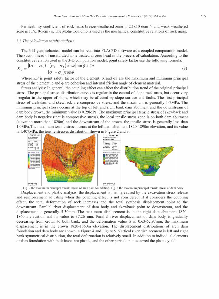
Stress analysis: In general, the coupling effect can affect the distribution trend of the original principal stress. The principal stress distribution curves is regular in the central of slope rock mass, but occur very irregular in the upper of slope, which may be affected by slope surface and faults. The first principal stress of arch dam and skewback are compressive stress, and the maximum is generally 1-7MPa. The minimum principal stress occurs at the top of left and right bank dam abutment and the downstream of dam body crown, the minimum value is 0.29MPa. The maximum principal tensile stress of skewback and dam body is negative (that is compressive stress), the local tensile stress zone is on both dam abutment (elevation more than 1820m) and the downstream of the crown, the tensile stress is generally less than 1.0MPa.The maximum tensile stress occurs at the left dam abutment 1820-1890m elevation, and its value is 1.407MPa, the tensile stresses distribution shown in Figure 2 and 3.
Fig. 2 the maximum principal tensile stress of arch dam foundation. Fig. 3 the maximum principal tensile stress of dam body Displacement and plastic analysis: the displacement is mainly caused by the excavation stress release
and reinforcement adjusting when the coupling effect is not considered. If it considers the coupling effect, the total deformation of rock increases and the total synthesis displacement point to the downstream. Parallel river displacement of dam body and skewback point to downstream, and the displacement is generally 5-30mm. The maximum displacement is in the right dam abutment 1820-1860m elevation and its value is 37.26 mm. Parallel river displacement of dam body is gradually decreasing from crown to both bank, and the deformation value is in 0.63-62.97mm, the maximum displacement is in the crown 1820-1860m elevation. The displacement distributions of arch dam foundation and dam body are shown in Figure 4 and Figure 5. Vertical river displacement is left and right bank symmetrical distribution, the total deformation is relatively small. In addition to individual elements of dam foundation with fault have into plastic, and the other parts do not occurred the plastic yield.
566 Huan Ling Wang and Miao He / Procedia Environmental Sciences 12 ( 2012 ) 561 – 567
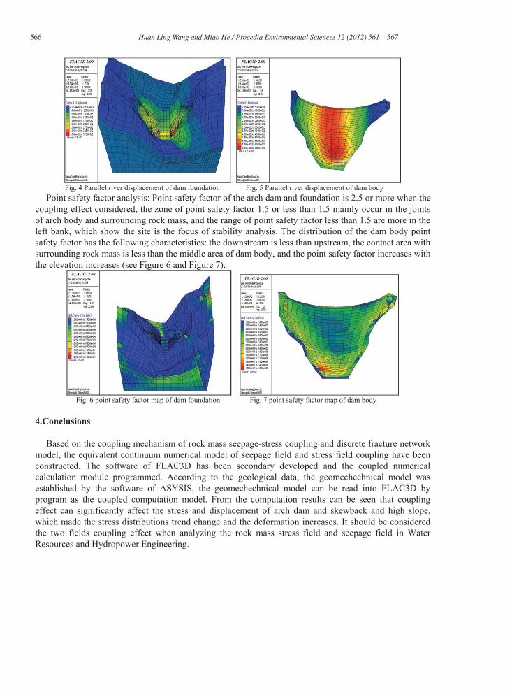
Fig. 4 Parallel river displacement of dam foundation Fig. 5 Parallel river displacement of dam body
Point safety factor analysis: Point safety factor of the arch dam and foundation is 2.5 or more when the coupling effect considered, the zone of point safety factor 1.5 or less than 1.5 mainly occur in the joints of arch body and surrounding rock mass, and the range of point safety factor less than 1.5 are more in the left bank, which show the site is the focus of stability analysis. The distribution of the dam body point safety factor has the following characteristics: the downstream is less than upstream, the contact area with surrounding rock mass is less than the middle area of dam body, and the point safety factor increases with the elevation increases (see Figure 6 and Figure 7).
Fig. 6 point safety factor map of dam foundation Fig. 7 point safety factor map of dam body
4.Conclusions
Based on the coupling mechanism of rock mass seepage-stress coupling and discrete fracture network model, the equivalent continuum numerical model of seepage field and stress field coupling have been constructed. The software of FLAC3D has been secondary developed and the coupled numerical calculation module programmed. According to the geological data, the geomechechnical model was established by the software of ASYSIS, the geomechechnical model can be read into FLAC3D by program as the coupled computation model. From the computation results can be seen that coupling effect can significantly affect the stress and displacement of arch dam and skewback and high slope, which made the stress distributions trend change and the deformation increases. It should be considered the two fields coupling effect when analyzing the rock mass stress field and seepage field in Water Resources and Hydropower Engineering.

567 Huan Ling Wang and Miao He / Procedia Environmental Sciences 12 ( 2012 ) 561 – 567
References
[1] J.L. Serafim, “Malpasset dam discussion-remembrances of failure of dams,” Engineering Geology, no. 2, pp. 355-366, 1987. [2] W. Wittke and G. A. Leonhards, “Modified hypothesis for failure of Malpasset dams, ” Engineering Geology, no. 24, pp.
367- 394, 1987. [3] L.Muller, “The rock slide in the Vajont Valley,” Rock Mech. Eng. Geol, no. 2, pp. 148-212, 1964. D.Savage, “The scientific and regulatory basis for the geological disposal of radioactive waste,” Chichester: John Wiley and
Sons, 1995 [4] U Wang, “Deep geological disposal of high-level radioactive waste in china,” In: Winter meeting of the united states of
nuclear waste technical review board. as Vegas, USA:[s.n.], p42-49, 1996 [5] R.Olsson, N.Barton, “An improved model for hydro mechanical coupling during shearing of rock joint,” Int J Rock Mech &
Mining Sci, no.38, p173-329, 2001 [6] H. S. Lee, T. F.Cho, “ Hydraulics characteristics of rough fractures in linear flow under normal and shear load,” Rock
Mechanics and Rock Engineering, vol.35, no.4 ,p299-318, 2002 [7] A. Makurat, N. Barton, S.Rad, “Joint conductivity variation due to normal and shear deformation,” In: Barton , N.,
Stephansson, O, ed. Rock joint, p299-318, 2000 [8] T. Esaki, S. Du, Y. Mitani, et al, “Development of shear-flow test apparatus and determination of coupled properties for a
single rock joint,” Int. J. Rock Mech. and Min.Sci , vol. 36, no. 5, p641-650,1999 [9] M.S.King, N.A. Chaudhry, A.Shakeel, “Experimental ultrasonic velocities and permeability for sandstones with aligned
cracks,” Int. J. Rock Mech. Min. Sci &Geomech.Abstr, vol. 32, no. 2, p155-163, 1999 [10] M. Bai, M. Meng, D.Elsworth, “Analysis of stress-dependent permeability in nonorthogonal flow and deformation field,”
Rock Mechanics and Rock Engineering, vol. 32, no.3, p195-219, 1999 [11] J.Liu, D.Elsworth, B. H.Brady, et al, “Strain-dependent fluid flow defined through rock mass classification schemes,” Rock
Mechanics and Rock Engineering, vol.33, no.3, p75-92, 2000 [12] Chang Soo-Ho, Lee Chung-In, Jeon Seokwon, “Measurement of rock fracture toughness under modes 1and 2 and mixed-
mode conditions by using disc-type specimens,” Engineering Geology, no.66, p79-97, 2002 [13] Tsang Chin-Fu, “Introductory editorial to the special issue on the DECOVALEX-THMC project,” Environ Geol , no.57,
p1217-1219, 2009 [14] Tsang Chin-Fu, Stephansson Ove, Jing Lanru, Fritz Kautsky, “DECOVALEX Project: from 1992 to 2007,” Environ Geol,
no.57 p1221-1237,2009 [15] Jonny Rutqvist, Deborah Barr, Jens T. Birkholzer, et al, “A comparative simulation study of coupled THM processes and
their effect on fractured rock permeability around nuclear waste repositories,” Environ Geol, no. 57 p1347-1360,2009 [16] G. Barla, M.Cravero and C.Fidelibus, “Comparing methods for the determination of the hydrological parameters of a ZD
equivalent Porous medium,” Int.J.Rock Mech. & Min.Sci., no.37, p1133-1141 , 2000 [17] T.Nakashima, N. Arihara and K.Sato, “ Effective Permeability estimation for modeling naturally fractured reservoirs,”
Paper Presented for the 2001 SPE Middle East oil Show, Bahrain, p17-20, 2001