architectural cfd simulation challenges - ibpsa · this paper discusses the capabilities and...
TRANSCRIPT

CFD ANALYSIS CHALLENGES IN BUILDING SIMULATIONFOR SIMBUILD2004 CONFERENCE
Ferdinand Schmid and Galen BurrellArchitectural Energy Corporation
ABSTRACTThis paper discusses the capabilities and challenges of computational fluid dynamic analysis (CFD) in thearchitectural engineering field. It is intended to provide a user's perspective of CFD challenges and not a scientificreport on cutting edge simulation techniques and algorithms. The combination of large dimensions with often nonorthogonal geometry poses a unique challenge to CFD software. Models quickly become very large and require morememory than some operating systems and workstations can provide. In addition to these model size issuesarchitectural models need to properly consider ambient weather conditions. Solar loading and the resulting buoyancydriven convection can completely change airflow patterns and comfort conditions in a building. Equally important isproper consideration of exterior wind pressure on building openings. Methods for determining these and otherboundary conditions are discussed. Changing weather conditions throughout the year require CFD analysis forseveral days of the year. Some problems cannot be solved in steady-state mode and require a transient analysis.Economic and project time limitations in the real world demand smart problem simplifications. A variety of methodsfor simplifying CFD problems without compromising the validity of the results are discussed.
INTRODUCTIONComputational Fluid Dynamic simulation is currently the most detailed building ventilation and comfort analysismethod. Air movement, building construction, exterior and interior boundary conditions, and even air compositionchanges are part of the simulation. This level of detail allows a precise analysis of building comfort beyond thermalcomfort. Unlike other building simulation systems, such as DOE2 (http://www.doe2.com), CFD does not assume fullair mixing. All air properties are calculated for thousands to millions of locations throughout the simulated space,which allows for analysis of thermal stratification. Humidity, mean age of air, and pollutants are part of the analysis.All of this detail comes at the expense of complexity and computational cost. However, there are many situationswhere the benefit of a CFD analysis far outweighs its cost.
Historically, CFD analysis was focused on fairly small geometries, such as automotive engines; and materialsciences, such as semiconductor manufacturing. The cost of CFD analyses in these situations was small compared tothe resulting value in the manufacturing environment. Larger scale CFD analysis was primarily found in academicand high-tech environments, such as aerospace engineering. Recent advances in computer processing power,combined with modern software, allow the application of CFD analysis to buildings. This paper describes how CFDworks, how it can be applied to building sciences, and what its current limitations are. The examples used are derivedfrom an analysis for a proposed National Museum of the Marine Corps in Quantico, Virginia. The simulationsoftware was Fluent Airpak. This paper is intended to provide a user's perspective of CFD challenges and not ascientific report on cutting edge simulation techniques and algorithms.
HOW CFD WORKS
System Overview
CFD analysis can be used to predict comfort and ventilation performance for a building during the design phase.
The input for CFD analysis is derived from available CAD drawings and information from the mechanical engineers.The architectural drawings contain many details that need to be removed for CFD analysis. Figure 1 and Figure 2show the dramatic level of simplification that was done to solve the example problem. This comparison shows thatCFD analysis of large, complex buildings requires far more than importing a CAD drawing into a software packageand pressing the start button.
SimBuild 2004, IBPSAUSA National Conference Boulder, CO, August 46, 20041

Computational Fluid Dynamics uses the concept of a computational domain, which encloses the analysis space. Inour example analysis we were interested in the interior space of the building. All fluid dynamic equations need to besatisfied for the computational domain (e.g. balance of energy into and out of the space). Appropriate boundaryconditions must be defined for the exterior surfaces. This includes pressure onto openings such as windows andexterior air temperature.
The CFD analysis is done by splitting the space of interest into a finite number of volume elements. A simpleexample would be splitting a rectangular room into a number of small cubes. This process of splitting the buildingspace into discrete volume elements is called meshing. During the analysis the software solves a set of differentialequations for continuity, energy, and x, y, and z velocity repeatedly until the change per iteration for all mesh cells isbelow a certain threshold. This process is called solving in steady-state mode. Some problems cannot be solved insteady-state mode because airflow patterns are unsteady. These dynamic cases require a transient analysis, whichrequires solving the model for a number of time increments.
Building Geometry and Meshing
Some architectural CFD systems can only solve models with a rectangular geometry efficiently because they offeronly a hexagonal mesher. For many situations, like data centers, this is an acceptable environment. However, thesimulation of complex landmark buildings requires a more sophisticated meshing approach, which Airpak providesthrough a tetrahedral mesher. A tetrahedral mesh can adjoin surfaces at any inclination and orientation angle.However, it is much more difficult to generate a tetrahedral mesh. Tetra solutions require up to an order ofmagnitude more computational time. This is caused in part by additional equation terms due to the non orthogonalnature of a tetra mesh. If solving a problem with 100,000 hexagonal grid cells takes 30 minutes, then solving aproblem with the same number of tetrahedral mesh cells will take many hours. It is important to limit the number ofgrid cells to an absolute minimum to control solver times. This requirement for problem simplification mandatesmanual work. Simply importing a three-dimensional architectural drawing into the CFD system would result in avery complex model. A better approach is to use the imported architectural drawing as a blueprint that can be tracedfor creating a suitable CFD representation of the building.
The example building shown in Figure 1 represents an architect's rendering of the proposed National Museum of theMarine Corps. The round public space of this building is underground. At its highest point the conical shaped glassroof rises 150 feet above its base. The purpose of the CFD simulation was to predict temperatures in the occupiedspace and in the roof area. CFD was also used to confirm that no condensation would occur at the glass roof duringevening banquets on winter nights.
SimBuild 2004, IBPSAUSA National Conference Boulder, CO, August 46, 20042
Figure 1 - Architect's Rendering of Example Building(Courtesy of Fentress Bradburn Architects)
Figure 2 - Thermal Profile (Vertical Cut)

Supply air for the building is only provided through nozzle diffusers on the perimeter of the occupied space. Thelarge glazed area of the roof produces a high solar gain that needs to be offset by the HVAC system.
Comparing Figure 1 and Figure 2 illustrates the below described simplifications, which were done to eliminate allnonessential details. The simplified model required a tetra mesh of about 800,000 grid cells, which is a small fractionof the grid cell number for a similar model with all architectural details.
The list of simplifications includes:
➢ The base of the building was approximated through planar walls:
This allows for easy placement of large return vents (rather than curved ones).Due to the large diameter of the building this simplification does not significantly impact airflow modeling.
The sloped glass surfaces of the roof can be aligned with the vertical walls without requiring odd shapedinterface pieces. Since convection is the only airflow in this region (slow velocity) this simplification won't cause differentairflow than a straight piece of glass that slightly overlaps a circular wall.
The supply vents can be perfectly aligned with the flat wall sections without requiring curved interface pieces.The CFD model has to be tight, without even minimal gaps between adjacent surfaces. Over the vent diameterthe curvature of the wall is minimal.
➢ The round supply air nozzles were approximated through square nozzles with identical physical properties likethrow, discharge velocity, and opening area. These square nozzles were much simpler to align to the walls thanround nozzles. The primary reason for this simplification are limitations of our CFD software, Airpak. Theselimitations of Airpak are not present in Fluent's general purpose CFD suite. However, Airpak's ease of use forarchitectural CFD outweighs this limitation.By the nature of its implementation (identical vent performance) this simplification doesn't affect the airflowpattern.
➢ The glass roof was simulated through planar inclined surfaces.Flow velocities close to the glass were expected to be very low, which was confirmed during the simulation.Stepped windows would cause mixing and other effects only when combined with moderate or fast airflow. Thelarger surface area of the stepped design was accounted for by adjusting the surface temperature of the glass.Differences in solar transmittance due to the different inclination and surface area were also compensated.
➢ All architectural detail around the glass was removed.As described above, differences in solar gain and shadingwere accounted for through manual calculations. Theexterior architectural details of the glazed roof were not partof the simulation so they were not needed in the model.
➢ The spire doesn't extend past the rooftop.The simulation only includes the building interior. Air ismechanically exhausted through the spire. The lack of amoderate stack effect through the removal of the extendedspire is insignificant due to the dominance of themechanical fans.
All of the geometry simplifications serve the primary goal ofsimplifying the solution mesh and thereby reducing solutiontime. The complex geometry of the example building mandatesthe use of a tetrahedral mesh. This mesh needs to offersufficient resolution near areas of high flow velocity. In wideopen areas, however, the mesh can be coarse to minimize thetotal number of grid cells for computational efficiency. Figure3 shows a vertical cut of the mesh with its coarse and fineareas.
SimBuild 2004, IBPSAUSA National Conference Boulder, CO, August 46, 20043
Figure 3 - Tetra Mesh
The quality of a mesh can be verified during the solution phase by comparing results from a simulation with a givenmesh to results from a simulation with a finer mesh. Mesh independent results confirm that the coarser version of themesh is sufficient. Future simulations like parametric studies with various boundary conditions can then be run withthe less detailed mesh version.
Boundary Conditions
As with the geometry, determining boundary conditions for a CFD model means finding the simplest accuratedescription of the objects surrounding the simulation space.
It is important to understand that a steady-state CFD simulation will only finish after all of the surface and fluidproperties change less than the convergence criteria defines. For example an interior wall surface will change itstemperature until it reaches a point where the thermal conduction to the outside is equivalent to the thermal exchange(convection, conduction, radiation) on the inside. The thermal mass of the wall cannot be considered in a steady-stateanalysis. With this limitation in mind it is often advisable to simulate well insulated walls as adiabatic. The sameapplies to interior walls that separate spaces with similar air temperatures. This reduces calculation effort without anysignificant impact on the simulation results.
The boundary conditions for our example building were defined as follows:
➢ Adiabatic walls and floor for the occupied space. Materials for these objects were assigned as appropriate toensure correct emissivity and other physical properties.
➢ The windows were simulated as glass with a given U value and transmittance (not adiabatic).
➢ The ambient conditions outside the building were defined through a combined solair temperature, which providescombined radiation and convective heat transfer data to the CFD software.
➢ No wind effects, such as pressure on building openings, were considered.
➢ The spire inside the building was simulated as a thermally conducting material (metal).
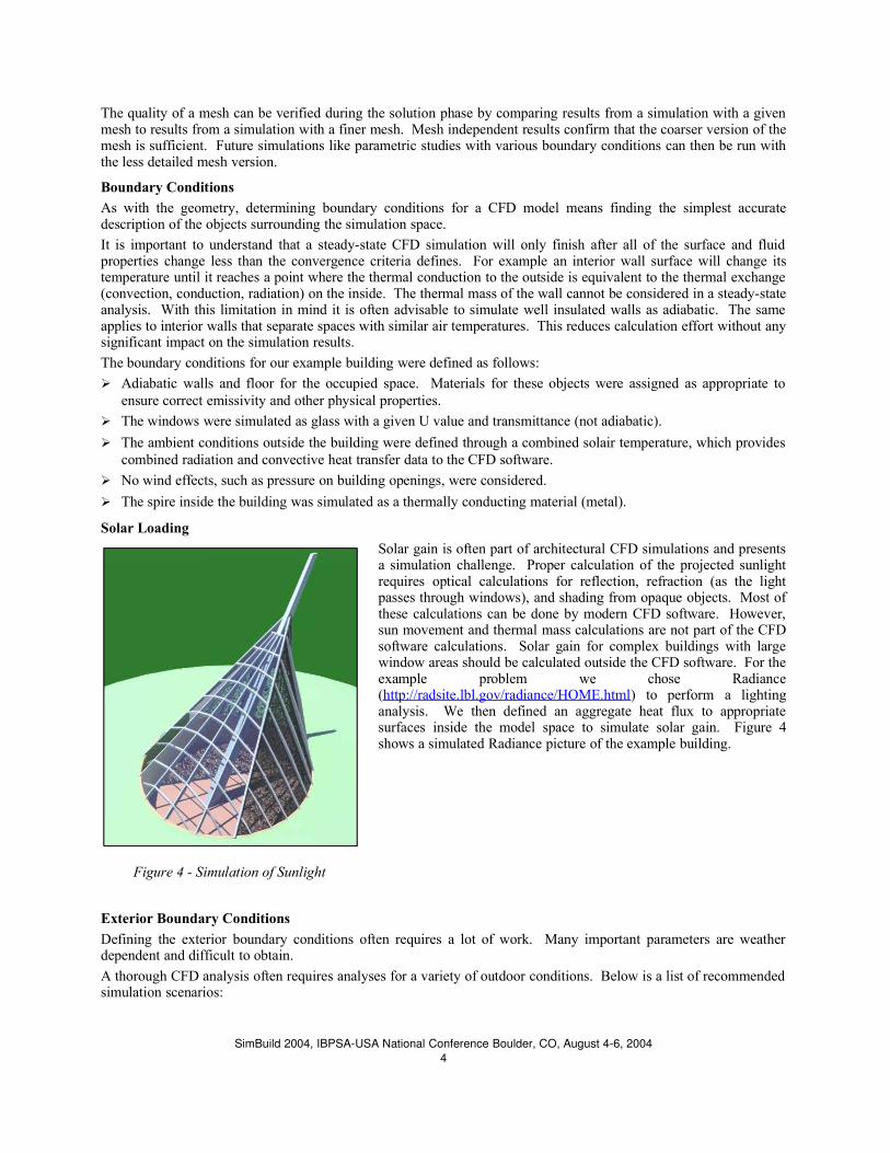
Solar Loading
Solar gain is often part of architectural CFD simulations and presentsa simulation challenge. Proper calculation of the projected sunlightrequires optical calculations for reflection, refraction (as the lightpasses through windows), and shading from opaque objects. Most ofthese calculations can be done by modern CFD software. However,sun movement and thermal mass calculations are not part of the CFDsoftware calculations. Solar gain for complex buildings with largewindow areas should be calculated outside the CFD software. For theexample problem we chose Radiance(http://radsite.lbl.gov/radiance/HOME.html) to perform a lightinganalysis. We then defined an aggregate heat flux to appropriatesurfaces inside the model space to simulate solar gain. Figure 4shows a simulated Radiance picture of the example building.
Exterior Boundary Conditions
Defining the exterior boundary conditions often requires a lot of work. Many important parameters are weatherdependent and difficult to obtain.
A thorough CFD analysis often requires analyses for a variety of outdoor conditions. Below is a list of recommendedsimulation scenarios:
SimBuild 2004, IBPSAUSA National Conference Boulder, CO, August 46, 20044
Figure 4 - Simulation of Sunlight

➢ Simulation of the hottest expected day and time is necessary to confirm proper cooling and comfort during peaksummer heat. Certain types of spaces, e.g. higher zones of atria, don't need to fully satisfy ASHRAE comfortconditions during the hottest hours of summer.
➢ A typical summer day simulation is required to verify that a proposed cooling design can provide comfort.
➢ Simulation of the coldest possible winter condition is used to verify that the heating system is capable ofmaintaining adequate temperature and humidity. In some cases, condensation on exterior surfaces is also aconcern that needs to be analyzed.
Some of the above scenarios need to be solved for a variety of ventilation scenarios. The CFD analysis may be usedto reduce HVAC equipment costs through the addition of natural ventilation, shading devices, or other energyconservation technologies.
Wind is another exterior boundary condition challenge. It generates positive and negative pressure on operablewindows and vents. Accurate calculation of wind pressure for openings often mandates an exterior CFD simulationto properly consider building architecture and the impact from surrounding buildings and trees. A conservative CFDanalysis requires several solutions with various wind speeds from all common wind directions.
As mentioned before the thermal exchange of a building with its environment can often be simplified through the useof solair temperatures. Solair temperatures combine radiative, convective, and conductive heat exchange. For wellinsulated buildings this simplified approach offers significant time savings without sacrificing accuracy.
Solving
The next step after defining geometry, mesh, and boundary conditions is solving the CFD model. This step requiresentering a few more parameters, such as selection of a turbulence model (we chose the zero equation indoor model),single or double precision solver, under-relaxation factors, and other solver specific information. Default values are agood starting point but if a solution doesn't converge, changing solver parameters can often solve the problem.
Depending on the size of the CFD model, it can bedesirable to use multiple CPUs during the solutionprocess. When using multiple CPUs the CFD softwaresplits the model into sections and each section can then besolved independently by one CPU. Experience shows thatthere is little benefit from splitting a CFD model intosmaller pieces than 200,000 mesh cells per CPU. We usedthree dual CPU machines running SuSE Linux(http://www.suse.com) for our simulations. We found thatrunning three concurrent simulations on two CPUs eachprovided the best efficiency for the example problem.
Airpak's solver allows the use of SMP (Shared MemoryProcessing) systems or a cluster of computers withindependent memory. Supported operating systemsinclude Linux and Microsoft Windows.
Fluent also offers a Remote Solving Facility (RSF), whichallows users to solve their problem on a large Unix systemwith significantly more capability than any workstationcan offer. This can be a cost-effective solution for solvingmany scenarios concurrently and fast. Their fees arebased on CPU hours (computation effort).
It is important to watch the residual plots during thesolution phase for efficient solving. Once the residualplots diverge there is no point in continuing the solutionphase. Figure 5 shows the residual plots for the first 100
iterations during the solution phase of one of the example runs. The convergence criteria is set to 0.001, which meansthat none of the values may change more than 0.1% between two iterations. The graph shows that a completesolution for this simulation requires many hundred iterations. An increase in residual values indicates a divergingsolution and requires intervention. Sometimes the residuals simply flatten out to a horizontal line, which also
SimBuild 2004, IBPSAUSA National Conference Boulder, CO, August 46, 20045
Figure 5 - Residual Plots from Airpak Solver
indicates a problem. Problem solving at this point requires a good understanding of physics and experience. It maybe necessary to modify some of the above mentioned solver parameters. Other potential input problems include a notperfectly sealed simulation volume or, as is frequently the case, mesh problems. However, it is also possible that thesolution cannot converge because there isn't a stable flow regime for the modeled space. An example would be alarge space with low ceiling and no air supply or return (sealed box). If the floor represents a uniform heat source,convection will start in one spot. However, air from the ceiling gets displaced and needs to flow back down. Sincethere is no favorable space for the location of rising air and dropping air, the rising air plume will migrate over time.This problem cannot be solved in steady-state mode. Problems of this type need to be solved in transient mode. TheCFD software will then attempt to solve the model for a finite number of time iterations. Transient solutions multiplythe solver time but they are sometimes the only option for solving a CFD problem.
A converged solution does not prove correct results. The results from a CFD simulation require rigorous analysisduring post processing to confirm their accuracy. This includes checking the energy balance of the simulation,checking for temperature, pressure, and flow velocity extremes; and verification that the calculated flow regime isrealistic.
Post Processing
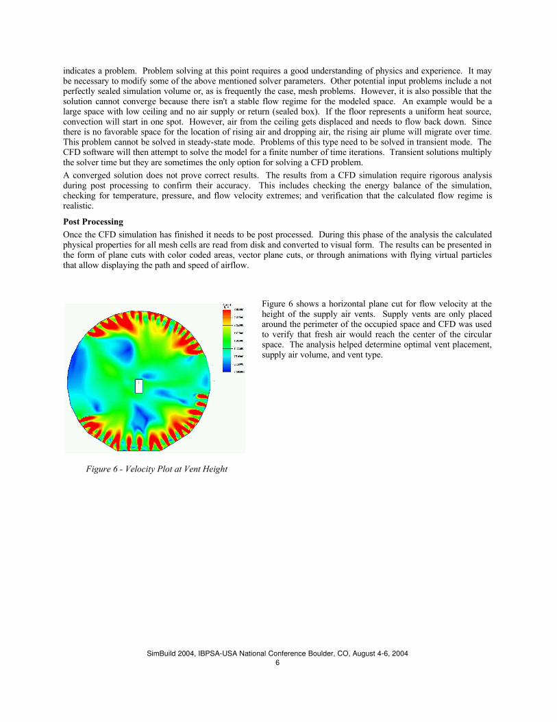
Once the CFD simulation has finished it needs to be post processed. During this phase of the analysis the calculatedphysical properties for all mesh cells are read from disk and converted to visual form. The results can be presented inthe form of plane cuts with color coded areas, vector plane cuts, or through animations with flying virtual particlesthat allow displaying the path and speed of airflow.
Figure 6 shows a horizontal plane cut for flow velocity at theheight of the supply air vents. Supply vents are only placedaround the perimeter of the occupied space and CFD was usedto verify that fresh air would reach the center of the circularspace. The analysis helped determine optimal vent placement,supply air volume, and vent type.
SimBuild 2004, IBPSAUSA National Conference Boulder, CO, August 46, 20046
Figure 6 - Velocity Plot at Vent Height

Figure 7 shows the flow at vent level as a vector plot. Thismacroscopic overview illustrates the general flow patterninside the space at vent level.
Figure 8 shows temperature in a horizontal plane cut sixfeet above ground during peak summer conditions. Atemperature probe in the picture shows the temperature atits location. This software feature lets users explorephysical property details in arbitrary locations. Thepicture shows that there are warm spots within theconditioned space, as is the case in real buildings.Without a CFD analysis it would be impossible to predictsuch details and the magnitude of the temperaturedifferences throughout the space. As stated before mostconventional simulation software assumes perfectlymixed air.
SimBuild 2004, IBPSAUSA National Conference Boulder, CO, August 46, 20047
Figure 7 - Vector Plot of Flow at Supply Vent Level
Figure 8 - Horizontal Cut Temperature Plot at six FeetAbove Ground

Vertical plane cut temperature graphs as shown in Figures 1and 9 complement horizontal views. They show thattemperature stratification occurs inside the building and thatthe temperature in the occupied space is within its allowablerange. They also confirm that the peak temperature at thetop of the roof is within acceptable limits, thanks to theexhaust system, which is placed at the top of the spire.
The most important performance goal for HVAC systems iscomfort, which depends on humidity, air movement, andradiation in addition to temperature. Airpak is capable ofcalculating a comfort metric called Predicted Mean Vote.Positive PMV indicates the percentage of the population(people) who are too hot, negative numbers indicate thepercentage of the population that are too cold. Of courseclothing matters for this assessment. Figure 10 shows avertical plane cut PMV graph for building occupants wearingshort sleeve shirts and light trousers, doing moderatephysical activity (standing and walking).
SimBuild 2004, IBPSAUSA National Conference Boulder, CO, August 46, 20048
Figure 10 - Vertical Plane Cut For Predicted MeanVote (PMV)
Figure 9- Vertical Plane Temperature Profile

Another valuable air quality metric is the mean age of air.CFD calculates all the required data to analyze the meanage of air. This metric is especially important in spaceswith high occupancy and in rooms with pollutingequipment, such as photocopiers. Figure 11 presents themean age of air for one of the ventilation scenarios in ourexample building. The mean age of air in the occupiedzone is between five and seven minutes, which isacceptable.
Conclusion
Computational Fluid Dynamic analysis for complex buildings requires significantly more effort than conventionalbuilding simulation, such as DOE2 models. The simulated building needs to be simplified through careful analysis tocreate a representative model without any unnecessary detail. This simplification may require hand calculations andeven computer simulations. Radiance is a good tool to analyze solar gain, DOE2 is suitable for predicting the peakcooling and heating day for the building, and external CFD simulations can be used to accurately predict windpressure on openings.
The computational effort for solving complex CFD models is significant. Simulating a complex building within theallowable time frame between architectural reviews may require access to at least a small cluster of computers.Combined hardware, labor, and software costs far exceed conventional building simulation costs.
The information from a CFD analysis is very valuable. CFD can help avoid millions of dollars in cost through anaccurate prediction of heating and cooling loads. It helps design better buildings with improved comfort. Theoperational costs of CFD optimized buildings is typically much lower due to more efficient HVAC designs, shadingsystems, and other technologies; and the risk to architect and building owner when planning and building new andinnovative structures is significantly reduced.
Of course, not all CFD models are as complicated as our example building. There can be very good reasons to do aCFD analysis in simple buildings. If smoke or pollutant management, quality of air at a detail level, or other detailventilation aspects are important, then CFD is the answer. Examples could be airport terminals, factories, serverrooms, and a long list of other applications. The required skill and computing resources are much lower for structureswith a simple geometry, which makes CFD even more attractive.
ACKNOWLEDGMENTS• We would like to thank Fentress Bradburn Architects (http://www.fentressbradburn.com) for allowing us to use
their rendering of the proposed National Museum of the Marine Corps. We also thank them for permitting us touse CFD images that resulted from the above project in this paper.
• We would like to thank Mr. Walter Schwarz and Mr. Viralkumar Gandhi for their outstanding expert support forFluent Airpak.
SimBuild 2004, IBPSAUSA National Conference Boulder, CO, August 46, 20049
Figure 11- Mean Age Of Air Plane Cuts