architectural testing - crl-arch€¦ · astm f 1642-04/gsa ts01 test report rendered to: united...
TRANSCRIPT

AST M F 1642-04/GSA TS01 T EST R EPO R T
Rendered to:
UNI T E D ST A T ES A L U M INU M
SE RI ES/M O D E L : B W3250
PR O DU C T T YPE : A luminum Combination F ixed Window
Summary of Results
T itle T est Specimen #1
T est Specimen #2
T est Specimen #3
T est Specimen #4
ASTM Hazard Rating Very Low Hazard
Very Low Hazard Low Hazard Low Hazard
GSA Performance Condition 4 2 4 4 Average Peak Blast Pressure 6.7 psi 6.6 psi 7.1 psi 7.2 psi
Average Positive Phase Impulse 47 psi-msec 45 psi-msec 47 psi-msec 46 psi-msec Average Positive Phase Duration 13 sec 13 msec 14 msec 13 msec
This report contains in its entirety: Cover Page: 1 page Report Body: 9 pages Test Facility: 1 page Pressure-Time Plots: 8 pages Photographs: 8 pages Drawings: 20 pages
Reference should be made to Architectural Testing, Inc. Report No. A8997.01-122-12 for complete test specimen description and data.
Architectural Testing
130 Derry Court
York, PA 17406-8405
phone: 717-764-7700
fax: 717-764-4129
www.archtest.com
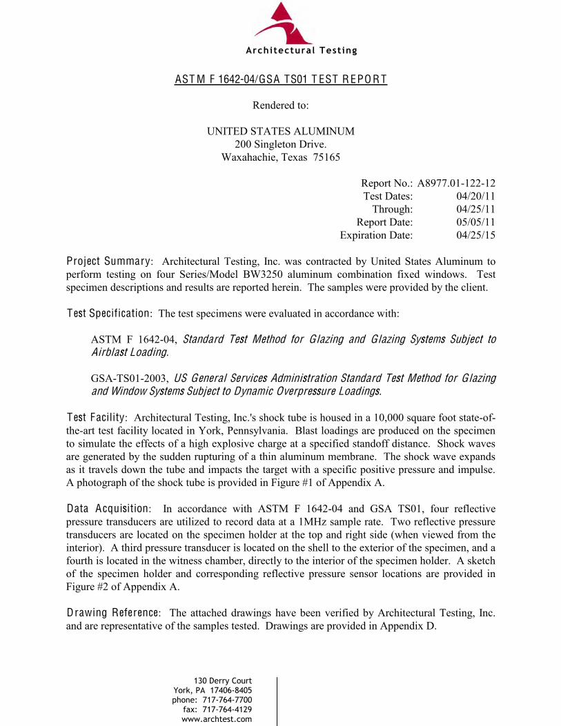
AST M F 1642-04/GSA TS01 T EST R EPO R T
Rendered to:
UNITED STATES ALUMINUM 200 Singleton Drive.
Waxahachie, Texas 75165
Report No.: A8977.01-122-12 Test Dates: 04/20/11 Through: 04/25/11 Report Date: 05/05/11
Expiration Date: 04/25/15 Project Summary: Architectural Testing, Inc. was contracted by United States Aluminum to perform testing on four Series/Model BW3250 aluminum combination fixed windows. Test specimen descriptions and results are reported herein. The samples were provided by the client. T est Specification: The test specimens were evaluated in accordance with: ASTM F 1642-04, Standard Test Method for Glazing and Glazing Systems Subject to
Airblast Loading.
GSA-TS01-2003, US General Services Administration Standard Test Method for Glazing
and Window Systems Subject to Dynamic Overpressure Loadings. T est Facility: Architectural Testing, Inc.'s shock tube is housed in a 10,000 square foot state-of-the-art test facility located in York, Pennsylvania. Blast loadings are produced on the specimen to simulate the effects of a high explosive charge at a specified standoff distance. Shock waves are generated by the sudden rupturing of a thin aluminum membrane. The shock wave expands as it travels down the tube and impacts the target with a specific positive pressure and impulse. A photograph of the shock tube is provided in Figure #1 of Appendix A. Data A cquisition: In accordance with ASTM F 1642-04 and GSA TS01, four reflective pressure transducers are utilized to record data at a 1MHz sample rate. Two reflective pressure transducers are located on the specimen holder at the top and right side (when viewed from the interior). A third pressure transducer is located on the shell to the exterior of the specimen, and a fourth is located in the witness chamber, directly to the interior of the specimen holder. A sketch of the specimen holder and corresponding reflective pressure sensor locations are provided in Figure #2 of Appendix A. Drawing Reference: The attached drawings have been verified by Architectural Testing, Inc. and are representative of the samples tested. Drawings are provided in Appendix D.
Architectural Testing
130 Derry Court
York, PA 17406-8405
phone: 717-764-7700
fax: 717-764-4129
www.archtest.com

A8977.01-122-12 Page 2 of 9
T est Specimen Description: The following descriptions apply to all specimens.
T est Series/Model: BW3250 System Product Type: Combination Fixed Window Overall Size: 82-3/4" wide by 82-3/4" high Interior Top L eft F ixed Daylight Opening: 23" wide by 69-1/2" high Interior Top Right F ixed Daylight Opening: 52-1/2" wide by 69-1/2" high Interior Bottom L eft F ixed Daylight Opening: 23" wide by 6" high Interior Bottom Right F ixed Daylight Opening: 52-1/2" wide by 6" high Overall A rea: 47.55ft2 Reinforcement: No reinforcement was utilized. F inish: Aluminum
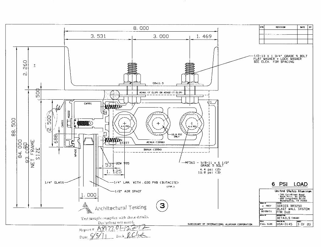
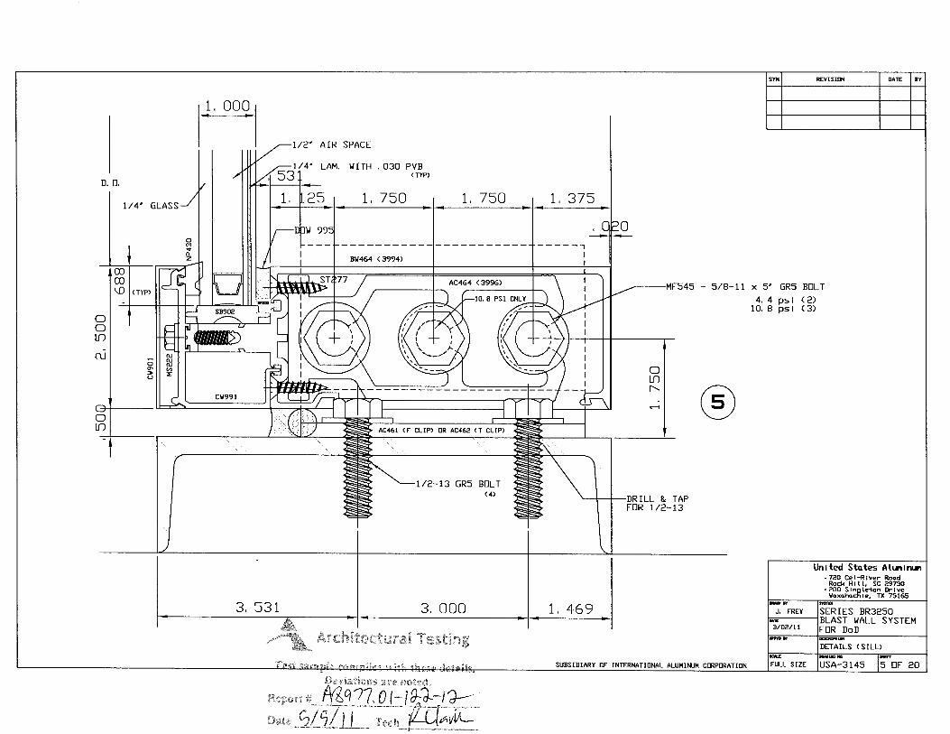
Glazing Details: Each lite was glazed with a 1" thick insulating glass unit. The outboard lite was constructed of 1/4" thick clear annealed glass and the inboard lite was constructed of 1/4" thick clear laminated glass separated by an aluminum spacer system. The laminated glass was constructed of two sheets of 1/8" thick clear annealed glass separated by a 0.030" thick PVB Butacite® interlayer. The glazing was installed from the exterior onto a bed of silicone sealant with a rubber gasket spacer against the glass. The exterior side was secured with an aluminum pressure plate and rubber gasket. The pressure plate was secured to the screw race of the framing members with 1/4" x 1" hex head screws spaced approximately 9" on center. The glazing bite measured 5/8". An aluminum snap cover was installed over the pressure plate. Note #1: The tested glazing represents the minimum allowable glazing thickness as per section B-3.1.1.1 and Table B-3.
Architectural Testing

A8977.01-122-12 Page 3 of 9
T est Specimen Description: (Continued)
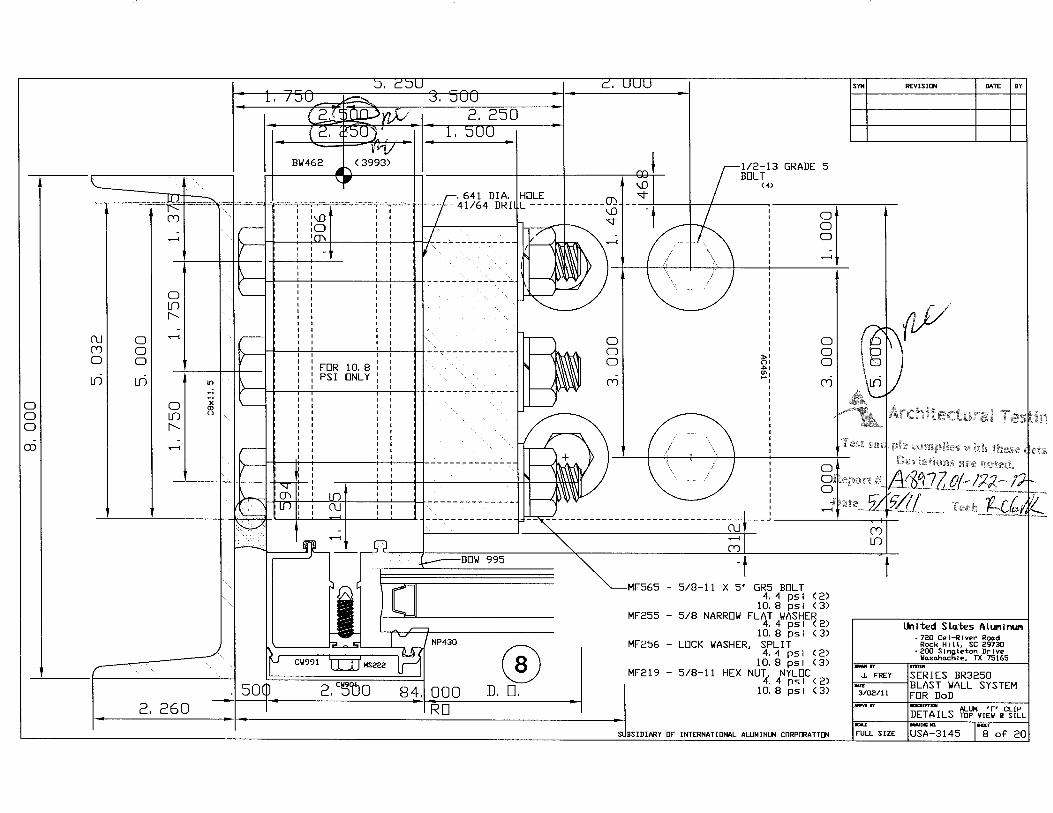
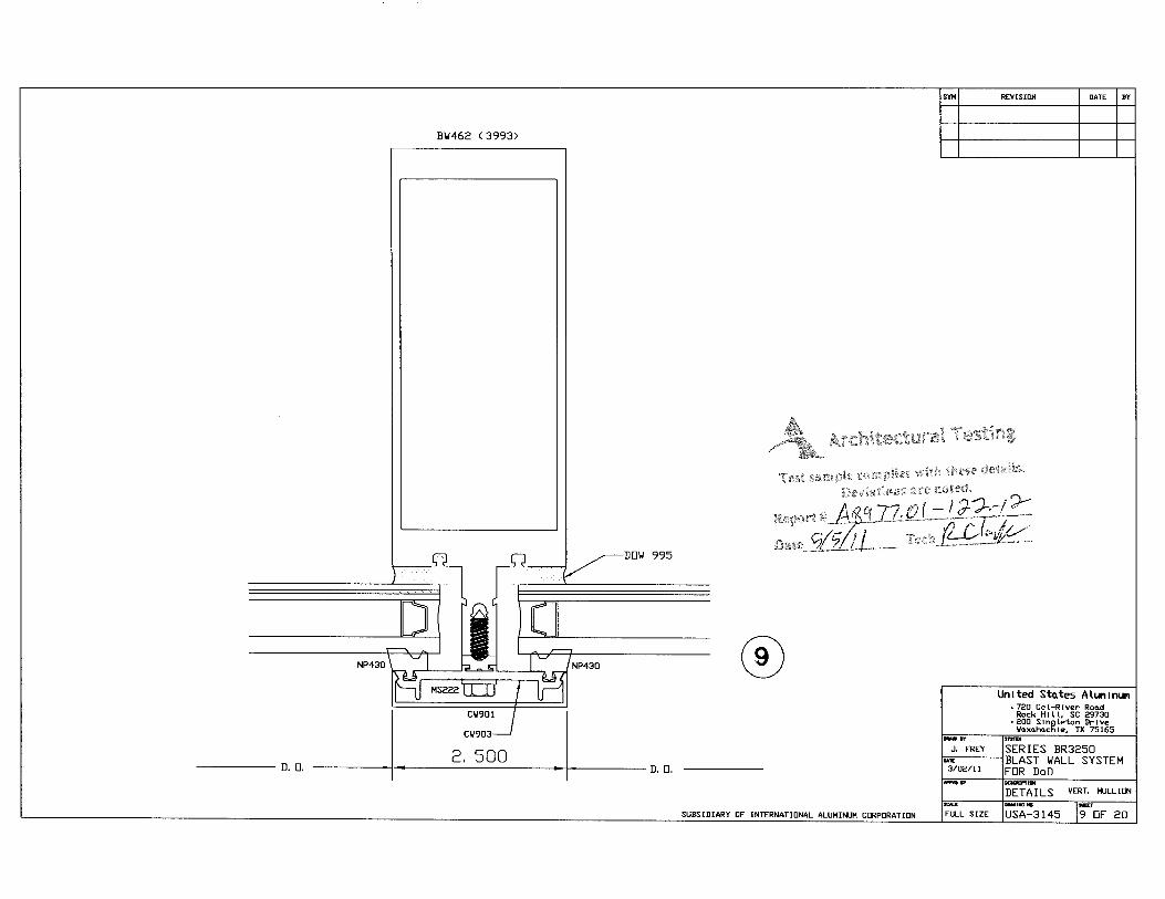
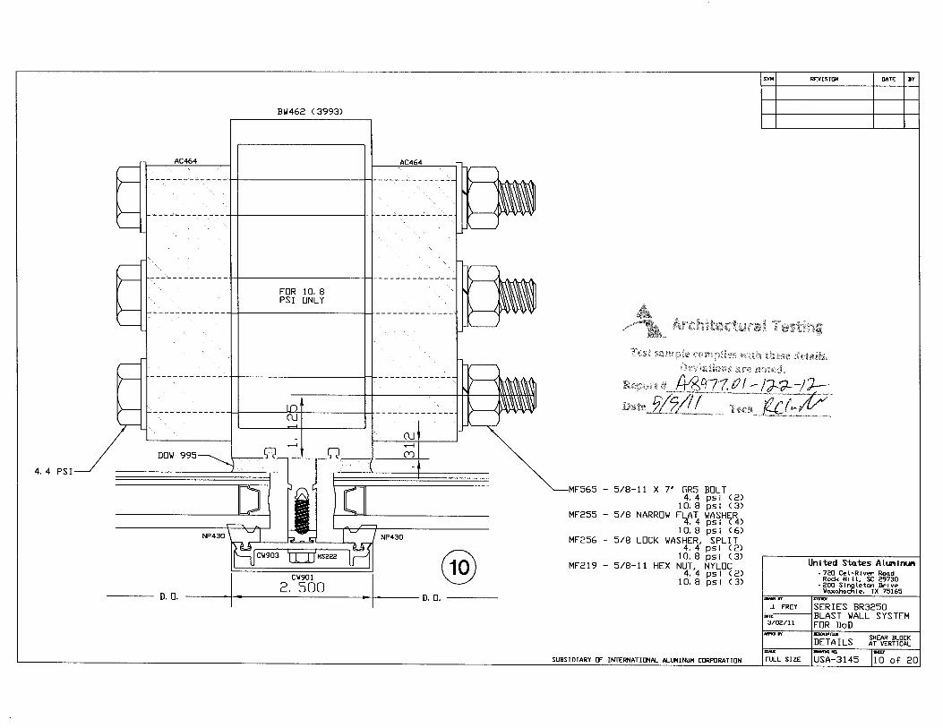
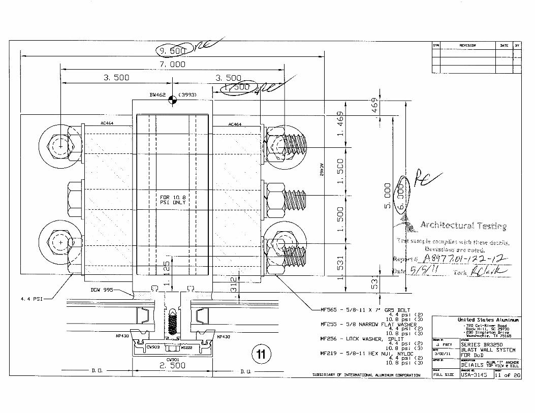
F rame Construction: All frame members were constructed of extruded aluminum, with coped and butted corners and sealed with silicone sealant. All horizontal to vertical connections utilized a shear block. Three 5/8" x 5" long bolts were used at each shear block connection to the vertical jambs and three 5/8" x 7" long bolts were used at all shear block connection to the intermediate mullion. Bolts extended through the vertical member and shear block and were secured with a washer and lock nut. Horizontal members were secured to the shear block with four #12 x 1" flat head screws extending through the horizontal into the shear block.
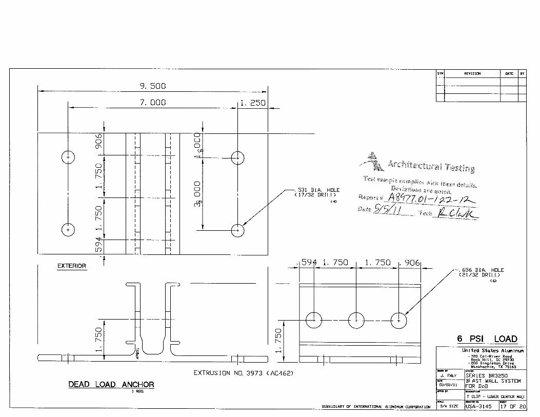
Hardware: No hardware was utilized. Installation: Each specimen was installed into a C8 steel channel test buck. "F" and "T" style anchors were used at the head and sill of the intermediate vertical mullion and at the head and sill of each vertical jamb member. "F" style anchors were secured to the steel channel with four 1/2" grade 5 bolts in a 2" x 3" square pattern in the center of the "F" style anchor. "T" style anchors were secured to the steel channel with four 1/2" grade 5 bolts, two bolts on each side of the anchor, 1-1/4" in from each end spaced 3" apart.
Architectural Testing

A8977.01-122-12 Page 4 of 9
T est Results: The results are tabulated as follows:
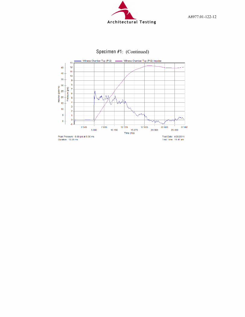
T est Specimen #1: Description Results Ambient Temperature 63ºF Glazing Temperature 66ºF Peak Positive Pressure Top Pressure 6.7 psi Right Pressure 7.1 psi Shell Pressure 6.3 psi Average Pressure 6.7 psi Positive Phase Duration Top Duration 13 msec Right Duration 14 msec Shell Duration 11 msec Average Duration 13 msec Positive Phase Impulse Top Impulse 47 psi-msec Right Impulse 47 psi-msec Shell Impulse 46 psi-msec Average Impulse 47 psi-msec
- No pressure rise was measured on the protected side of the specimen.
- Two 24" long tears in the laminate of the large lite and approximately 8" pull-out along the left jamb. One tear approximately 16" long on the large side lite. Total tears and pull-out for the large lite was greater than 20% of the sight perimeter.
- Fragments were observed in the witness area, with a sum total united dimension less
than 10" in the 1m-3m area. Three impacts on the back wall were observed below the 24" line.
ASTM Hazard Rating: Very Low Hazard GSA Performance Condition: 4 Pressure-time plots are presented in Appendix B. Pre-test and post-test photographs are provided in Appendix C.
Architectural Testing
A8977.01-122-12 Page 5 of 9
T est Results: (Continued)
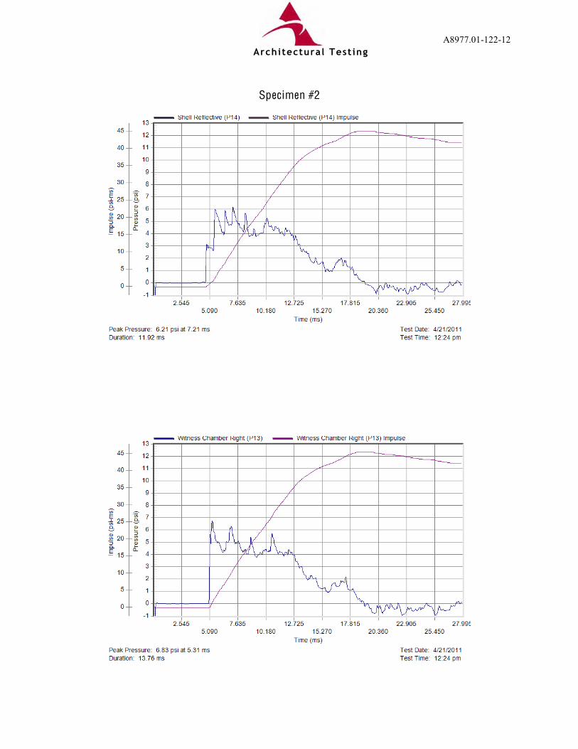
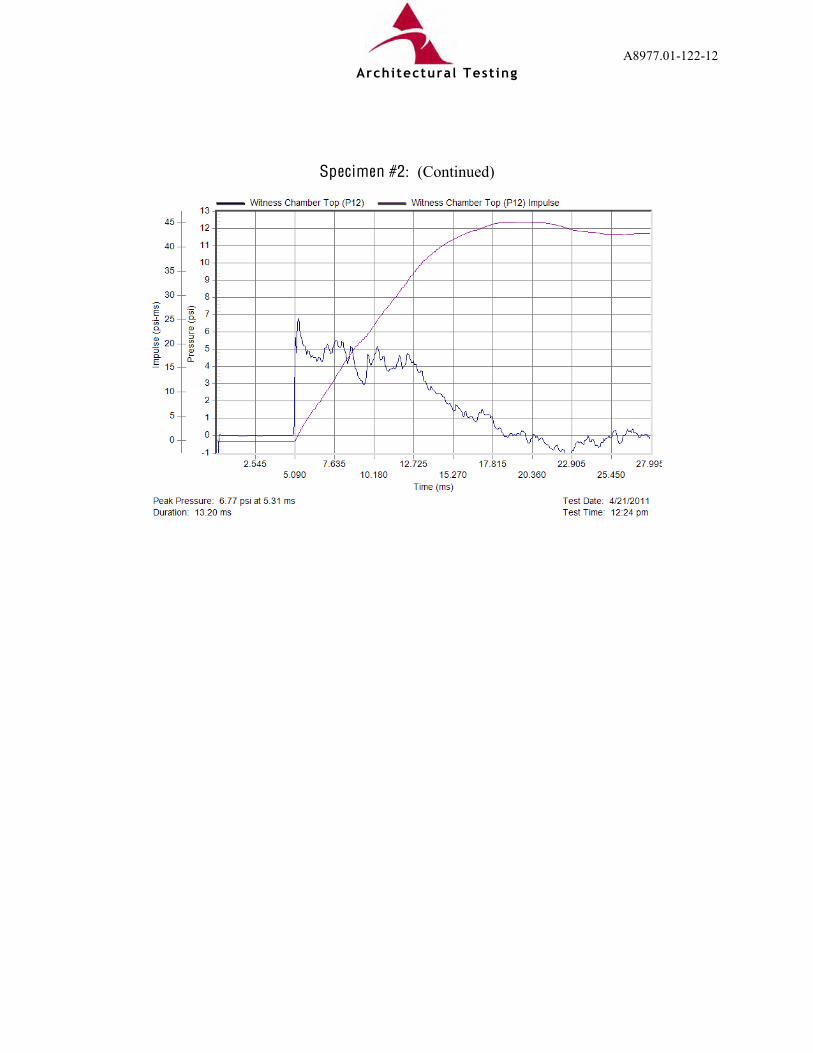
T est Specimen #2: Description Results Ambient Temperature 63ºF Glazing Temperature 64ºF Peak Positive Pressure Top Pressure 6.8 psi Right Pressure 6.8 psi Shell Pressure 6.2 psi Average Pressure 6.6 psi Positive Phase Duration Top Duration 13 msec Right Duration 14 msec Shell Duration 12 msec Average Duration 13 msec Positive Phase Impulse Top Impulse 46 psi-msec Right Impulse 45 psi-msec Shell Impulse 45 psi-msec Average Impulse 45 psi-msec
- No pressure rise was measured on the protected side of the specimen.
- A 14-1/2" tear in the laminate was observed at the top center of the large lite and 43" of pull-out was observed along the right jamb of the large lite. Total tears and pull-out for the large lite was greater than 20% of the sight perimeter.
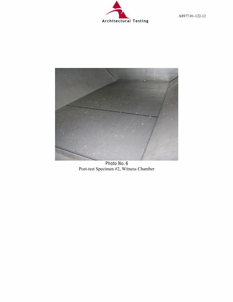
- Dusting of glass in the witness area. No fragments or damage to the back panel was
observed. ASTM Hazard Rating: Very Low Hazard GSA Performance Condition: 2 Pressure-time plots are presented in Appendix B. Pre-test and post-test photographs are provided in Appendix C.
Architectural Testing

A8977.01-122-12 Page 6 of 9
T est Results: (Continued)
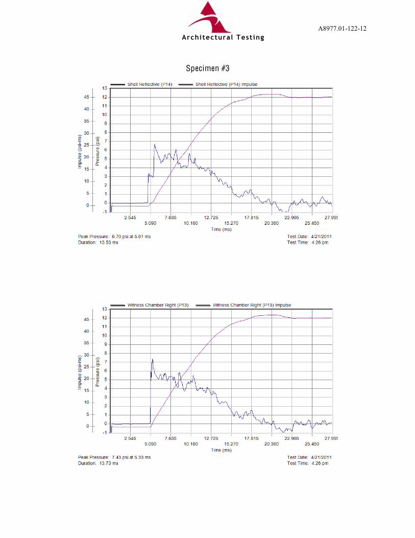
T est Specimen #3: Description Results Ambient Temperature 64ºF Glazing Temperature 64ºF Peak Positive Pressure Top Pressure 7.3 psi Right Pressure 7.4 psi Shell Pressure 6.7 psi Average Pressure 7.1 psi Positive Phase Duration Top Duration 13 msec Right Duration 14 msec Shell Duration 14 msec Average Duration 14 msec Positive Phase Impulse Top Impulse 47 psi-msec Right Impulse 47 psi-msec Shell Impulse 46 psi-msec Average Impulse 47 psi-msec
- No pressure rise was measured on the protected side of the specimen.
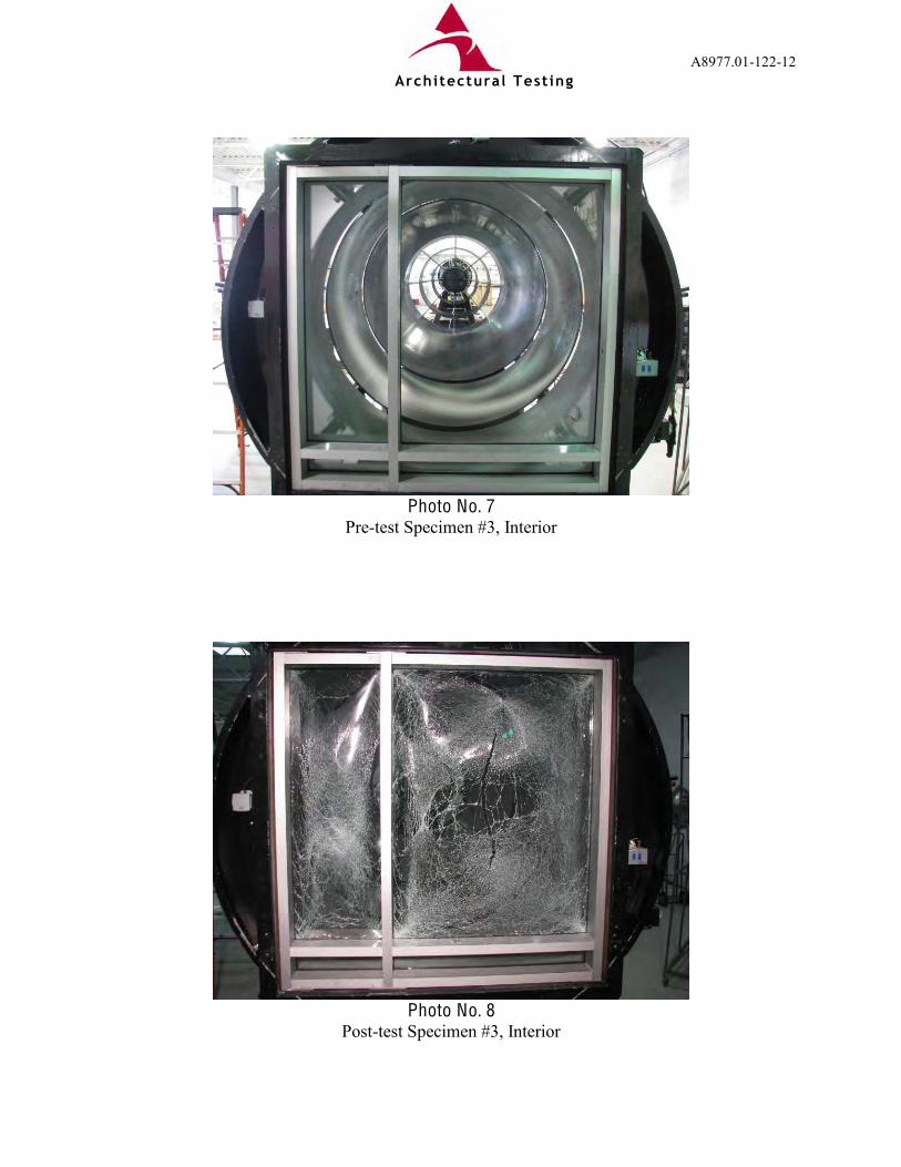
- A 43" long vertical tear in the laminate was observed at the center of the large lite. No pull-out was observed at the perimeter glazing.
- Multiple fragments were observed in the witness area with approximately 63" sum total
united dimensions in the 1m-3m area. Thirteen indents were observed in the wall panel below the 24" line.
ASTM Hazard Rating: Low Hazard GSA Performance Condition: 4 Pressure-time plots are presented in Appendix B. Pre-test and post-test photographs are provided in Appendix C.
Architectural Testing

A8977.01-122-12 Page 7 of 9
T est Results: (Continued) T est Specimen #4: Description Results Ambient Temperature 65ºF Glazing Temperature 67ºF Peak Positive Pressure Top Pressure 7.3 psi Right Pressure 7.4 psi Shell Pressure 6.8 psi Average Pressure 7.2 psi Positive Phase Duration Top Duration 13 msec Right Duration 13 msec Shell Duration 13 msec Average Duration 13 msec Positive Phase Impulse Top Impulse 46 psi-msec Right Impulse 47 psi-msec Shell Impulse 46 psi-msec Average Impulse 46 psi-msec
- No pressure rise was measured on the protected side of the specimen.
- A 43" horizontal tear in the laminate was observed at the center of the large lite, 39-1/2" of pull-out was observed out along the mullion and 29-1/2" pull-out was observed along the left jamb of the large lite. Total tears and pull-out for the large lite was greater than 20% of the sight perimeter.
- Multiple fragments were observed in the witness area with approximately 14" sum total
united dimensions in the 1m-3m area. One fragment indent was observed on the back witness panel, 1" from the floor.
ASTM Hazard Rating: Low Hazard GSA Performance Condition: 4 Pressure-time plots are presented in Appendix B. Pre-test and post-test photographs are provided in Appendix C.
Architectural Testing
A8977.01-122-12 Page 8 of 9
L ist of O fficial Observers:
Name Company Brady W. McNaughton, P.E. Architectural Testing, Inc. Russell W. Clark Architectural Testing, Inc.
Detailed drawings, data sheets, representative samples of test specimens, a copy of this report, and other pertinent project documentation will be retained by Architectural Testing, Inc. for a period of four years from the original test date. At the end of this retention period, such materials shall be discarded without notice and the service life of this report will expire. Results obtained are tested values and were secured by using the designated test methods. This report does not constitute certification of this product nor an opinion or endorsement by this laboratory. It is the exclusive property of the client so named herein and relates only to the specimens tested. This report may not be reproduced, except in full, without the written approval of Architectural Testing, Inc. For ARCHITECTURAL TESTING, INC: _________________________________ _________________________________ Russell W. Clark Brady W. McNaughton, P.E. Technician Senior Project Engineer RWC:ddr/cmd Attachments (pages): This report is complete only when all attachments listed are included. Appendix-A: Test Facility (1) Appendix-B: Pressure-Time Plots (8) Appendix-C: Photographs (8) Appendix-D: Drawings (20)
Architectural Testing

A8977.01-122-12 Page 9 of 9
Revision Log
Rev. # Date Page(s) Revision(s)
0 05/05/11 N/A Original report issue
This report produced from controlled document template ATI 00368, issued 04/13/09.
Architectural Testing

A8977.01-122-12
Appendix A
T est Facility
Architectural Testing

A8977.01-122-12
F igure #1
Shock Tube and Test Facility
F igure #2
Pressure Sensor Locations
Architectural Testing

A8977.01-122-12
Appendix B
Pressure-T ime Plots
Architectural Testing

A8977.01-122-12
Specimen #1
Architectural Testing
A8977.01-122-12
Specimen #1: (Continued)
Architectural Testing
A8977.01-122-12
Specimen #2
Architectural Testing
A8977.01-122-12
Specimen #2: (Continued)
Architectural Testing
A8977.01-122-12
Specimen #3
Architectural Testing

A8977.01-122-12
Specimen #3: (Continued)
Architectural Testing

A8977.01-122-12
Specimen #4
Architectural Testing

A8977.01-122-12
Specimen #4: (Continued)
Architectural Testing

A8977.01-122-12
Appendix C
Photographs
Architectural Testing

A8977.01-122-12
Photo No. 1
Pre-test Specimen #1, Interior
Photo No. 2
Post-test Specimen #1, Interior
Architectural Testing

A8977.01-122-12
Photo No. 3
Post-test Specimen #1, Witness Chamber
Architectural Testing

A8977.01-122-12
Photo No. 4
Pre-test Specimen #2, Interior
Photo No. 5
Post-test Specimen #2, Interior
Architectural Testing
A8977.01-122-12
Photo No. 6
Post-test Specimen #2, Witness Chamber
Architectural Testing
A8977.01-122-12
Photo No. 7
Pre-test Specimen #3, Interior
Photo No. 8
Post-test Specimen #3, Interior
Architectural Testing

A8977.01-122-12
Photo No. 9
Post-test Specimen #3, Witness Chamber
Architectural Testing

A8977.01-122-12
Photo No. 10
Pre-test Specimen #4, Interior
Photo No. 11
Post-test Specimen #4, Interior
Architectural Testing

A8977.01-122-12
Photo No. 12
Post-test Specimen #4, Witness Chamber
Architectural Testing

A8977.01-122-12
Appendix D
Drawings
Architectural Testing