architecture of faim-1kstevens/docs/computer87.pdf · teninaparallel formofprologthatis...
TRANSCRIPT

The Architecture of
FAIM-1
Judy M. Anderson, William S. Coates, Alan L. Davis, Robert W Hon,
Ian N. Robinson, Shane V. Robison, and Kenneth S. Stevens
Schlumberger Palo Alto Research
FAIM-1 can be scaledto provide two tothree orders ofmagnitudeimprovement over
conventional AImachines withmi mal. 0mconvenmence toprogrammers.
T his article describes a symbolicmultiprocessing system calledFAIM-1.* FAIM-l is a highly con-
current, general-purpose, symbolic accel-erator for parallel Al symbolic computa-tion. The paramount goal of the FAIMproject is to produce an architecture thatcan be scaled to a configuration capable ofperformance improvements of two tothree orders of magnitude over conven-tional architectures. In the design ofFAIM-1, prime consideration was given toprogrammability, performance, extensi-bility, fault tolerance, and the cost-effective use of technology.
Programmability. Although theFAIM-1 machine architecture is uncon-ventional, the software environment pro-vides a concurrent programming languageand an application development systemthat are based on models familiar to mem-bers of the Al community. This environ-ment permits immediate evaluation of theFAIM-I architecture when that architec-ture is used for existing applications, and iteases the burden on programmers of fu-ture applications.
Performnce. Effective use of concur-rency is the primary mechanism employedby the FAIM-1 system to increase signifi-cantly performance over conventional se-quential systems. Hardware concurrencyis exploited in the operation of* the individual processing elements,* subsystems within the processingelements, and
Work on the FAIM (Fairchild Al Machine) projectwas begun at the Fairchild Research Laboratories andhas since moved to another research lab withinSchlumberger.
0018-9162/87/OIOD-0055S01.00 i 1987 IEEE
* components within each subsystem.Software concurrency is exploited in twodistinct forms. Spatial concurrency in-volves a set of independent tasks, eachworking on a partitioned piece of theproblem. Temporal concurrency involvespipelined execution in which stages can beviewed as concurrent tasks operating onelements of a stream of data at differenttimes.
Extensibility. High priority was given tocreating a design permitting arbitrary ex-pansion of the hardware resources. Ex-pansion in FAIM-1 requires minimal re-wiring, and no modification to either theuser software or system software. Thecommunication topology is planar, andtherefore will not become a liability astechnology advances to permit evolutionfrom multiple-chip to single-chip process-ing elements. Wiring complexity scaleslinearly with processing-element count.All hardware module interfaces are self-timed I to permit individual componentsto evolve independently in performance,implementation technology, and function-ality. Self-timed circuit design is a type ofcircuit design discipline that does not use aglobal clock to guarantee synchroniza-tion. In this style, each component keepstime internally and provides interfacehandshaking signals to coordinate with itspartner subsystems. The result is an archi-tecture that is easy to modify and exhibits afavorable cost/performance ratio underscaling.
Fault toance. Any solution to thefault-tolerance problem inherently con-tains redundancy. The FAIM-l containssignificant redundancy, both in term's of
55January 1987
Authorized licensed use limited to: The University of Utah. Downloaded on August 15, 2009 at 11:06 from IEEE Xplore. Restrictions apply.

processing elements and in the way theseelements are interconnected. FAIM-1 isdesigned to be fault tolerant at the process-ing-element level, but not at the gate or cir-cuit level. The resource-allocation mecha-nism permits the reassignment of tasks toprocessors, the message-routing algorithmis capable of routing messages aroundfailed paths and processors, and the sys-tem software supports self-diagnosis.
Technology. The architecture is de-signed to take advantage of the cost andperformance of both advanced VLSI cir-cuit technology and advanced packagingtechnology (immersion-cooled wafer hy-bridization is an example of the latter) asthey become available.The focus of this article is on the physi-
cal architecture of the FAIM-1 system.However, to understand some of the de-sign decisions, one must examine the sa-lient aspects of both the software systemstructure and the programming languagethat the physical architecture supports.The next section ("Software structure")presents a synopsis of both topics; subse-quent sections present the hardwarearchitecture.
Software structureThe architecture of the FAIM-1 serves
as a high-speed evaluation engine for theconcurrent programming language OIL(Our Intermediate Language), and sup-ports a style of distributed multiprocessingsystem structure that is embodied in theruntime operating system.
The OIL language and OIL objects.OIL is a high-level, concurrent, symbolic-programming language. The design ofOIL was influenced by current AI pro-gramming practices, in which a number ofAI programming languages are widelyused. A distillation of these languagesleaves three main linguistic styles: object-oriented programming, logic program-ming (primarily Prolog), and proceduralprogramming (primarily Lisp). A complexAl application may require several (or all)of these programming styles. Emulatingone programming style within another isinefficient, so there is a need for a betterlinguistic mechanism, one that efficientlyincorporates or efficiently supports the es-sential features of the major styles. OILhas been designed to provide concurrentversions of each of the three linguisticstyles.
An OIL program is a collection of ob-jects that communicate by sending mes-sages. The nature of the communicationstructure explicitly indicates the top levelof concurrency represented by the pro-gram. Individual objects may themselvesbe concurrent program fragments. AnOIL object consists of some local state in-formation (typically in the form of vari-ables) and several ports through whichmessages are sent and received in FIFOorder. A behavior, associated with eachport, describes what the object does inresponse to a message. The behavior is aprogram that may modify the local stateand/or send messages to other objects.Atomic OIL objects are of two distincttypes: logical and procedural. Logicalbehaviors are written in a declarative stylesimilar to a parallel version of Prolog.2Procedural behaviors are written impera-tively in a lexically scoped dialect of Lispthat is similar to T. 3 Objects can be nestedheterogeneously to form other objects thatpermit control to pass between declarativeand imperative behaviors.An OIL object consists of9 state, which is represented as the col-lection of variables and data struc-tures that are considered local to theobject;
* ports, that is, the set of entry pointsthat may receive messages;
* entries (an entry is a subset of ports);and
* behaviors, that is, code that may beeither procedural or logical.
Objects can be created dynamically orstatically. Upon creation, the state of anobject is set to its initialization value. Anobject takes action when a message ar-rives. To support distributed procedurecalls and parallel process synchronization,subsets of ports may be grouped into en-tries. Behaviors are associated with entriesrather than ports. When all of an entry'sports have a message, then the associatedbehavior is said to be fireable. In caseswhere only a single port's message invokesa behavior, that port is also labelled as anentry. In cases where an object is defined interms of other objects, the inheritance isstatic.An object may consist of an arbitrary
number of behaviors and ports, and eachbehavior is viewed as a potentially inde-pendent code fragment. Since the object'sstate is accessible by any of that object'sbehaviors, a potential source of nondeter-minacy exists. To prevent this situation,the behaviors are viewed as a set of mutu-ally exclusive transactions. When a behav-
ior is started up, all other behaviors are in-hibited until that behavior terminates.Furthermore, a behavior may close portsand thereby temporarily inhibit messagedelivery on those ports until they aresubsequently re-opened.The roles of logic and procedural com-
ponents are quite distinct. The logic com-ponent is used to express in a succinctmanner nondeterministic pattern-drivensearch, while the procedural component isused for sequential algorithm specifica-tion, manipulating unique objects, and ex-pressing history-sensitive algorithms.Neither component projects its semanticson the other. Therefore, procedural ob-jects do not have multiple versions of theirenvironments, and logical objects do nothave changeable state variables. Commu-nication between logical and proceduralobjects is based on message streamsmanaged by manipulation of continua-tions in the sending and receiving objects.The exact semantic significance of contin-uations is somewhat different on eachside, but both use continuations as"handles" to obtain subsequent values ina stream. A logic component accepts aninput stream of goals, and produces anoutput stream of solutions. In general,there are several logical solutions per goal.A procedural component accepts an inputstream of function calls, and produces anoutput stream of response messages, usu-ally with one response per input functioncall.The binding of variables observes the
semantics of the object in which the vari-ables are defined. Thus, a logical variablehas multiple alternative bindings, in keep-ing with the nondeterministic semantics oflogic objects, and a procedural variablehas values that are changed by directassignment. Moreover, components arenot allowed to violate the binding policiesimposed by the variable's proprietor.Bound logic variables are invisible to pro-cedural accessors; instead, such accessesdirectly return the variable's value. Un-bound logic variables are detected as suchin procedural components, but cannot bebound by them. Procedural variables arepassed by value to logic components whenused in parameters. Hence, proceduralvariables (as assignable entities) are invisi-ble in logic components.The programmer may also annotate
OIL code with pragmas, which describesome of the expected runtime dynamic be-havior of the code. These programmer-supplied hints are used by the staticresource allocator to partition code and
COMPUTER56
Authorized licensed use limited to: The University of Utah. Downloaded on August 15, 2009 at 11:06 from IEEE Xplore. Restrictions apply.

data onto the physical resources ofthe ma-chine. The pragma information gives theprogrammer control over some aspects ofthe allocation strategy. Ifno pragma infor-mation is supplied, the program will stillrun, although perhaps not as efficiently.
Procedural OIL. The procedural com-ponent ofOIL is a parallel modification ofa lexically scoped dialect of Lisp called T. 3The primary modifications to T facilitatethe use ofconcurrency; they include a con-current reformulation of the basic seman-tics, and the addition of parallel controland data structures, operations on paralleldata structures, and specifiable evaluationstrategies that permit a variety of parallelevaluation methods. The primitive specialforms are exactly as defined byT with twoexceptions. The first exception involvesCond, which is the normal T conditional.Cond also exists in OIL, but Cond= hasbeen added, and is the parallel OIL ver-sion. Cond = causes the guards to evalu-ate in parallel, and the first one that evalu-ates to True is pursued. Semantically, thisimplies that an arbitrary evaluation of"True" by the guard forces selection,since the notion of what is first is not con-trollable by the programmer. The second isto permit special forms for specifyingpragmas and type infortnation. These are,respectively, the Pragma and Proclaimspecial forms. Pragmas fall into threecategories:
* estimates of the probability of takinga particular branch in a decision,
* estimates of the size of dynamic datastructures, and
* hints about appropriate allocationdecisions.
In all other respects procedural OIL isisomorphic to T.
Logical OIL. Logic behaviors are writ-ten in a parallel form of Prolog that is syn-tactically similar to DEC-10 Prolog. Thesame notation is used for clauses, lists, andseveral "evaluable predicates." In gener-al, operations such as arithmetic func-tions, which do not have an inherent se-quential semantics, are the same in bothlanguages. Operations like assert andretract are not supported.An OIL logical program consists ofa set
of named objects, each of which containsany number of clauses. The names of theobjects serve as names of worlds. The logicobjects can be nested, giving the effect ofadditional worlds. The programmer mayindicate a goal as solve(x,W), meaningthat goal x is to be solved in the context of
world W. This implies that the rules forsolving x are defined in world W. An innerworld inherits all the rules of the outerworlds. If the programmer omits the worldspecification, then a default single-worldmodel is used. The programnmer may alsoindicate private rules that are not inheritedby inner worlds. Logical objects differfrom procedural objects in that they can-not have internal state variables. Program-mers must use procedural code to describeoperations that modify an object's localstate. Variable bindings invoked underunification can affect local state only afterthey are passed back to a proceduralmodule, which assigns the value to one ofthe object's state variables.
Clauses of logic programs are compiledinto sets of primitive processes. Theseprimitive processes are objects that uselocal state variables to represent a portionof the global runtime environment. Theprocesses respond to incoming messagesby changing state and generating messagesfor other processes. The two types ofprimitive processes are AND processesand ORprocesses. AND processes executethe bodies of nonunit clauses, and ORprocesses manage execution of proceduresthat are defined by more than one clause.In the compiled logic program, there is atleast one AND process for the right handside of each nonunit clause, and at leastone OR process for each procedure (set ofclauses with heads that have the samefunctor and arity). An overall view of thecomputation would show an AND/ORprocess tree, with AND processes creatingOR descendants to solve each literal in agoal statement, and OR processes creatingAND descendants to solve bodies ofmatching clauses.
InAND processes, the basic actions, theinternal states, and the reaction to a partic-ular message depend on the desired con-trol model. The programmer may providemode declarations on logical variables; forexample, the literal p(x.?,y!) implies thatwhen p is evaluated, it will consume abinding for x and produce one for y. Theparallelism in logical OIL is primarily thenondeterministic pattern-directed searchmechanism that is obtained through ORparallelism. 4 Limited forms ofAND paral-lelism similar to that proposed by De-GrootI are also provided in cases where in-dependentAND processes can be identifiedat compile time or by a simple runtimeground check. The use of mode declara-tions significantly enhances the pro-grammer's ability to control the amountofAND parallelism that can be exploited.
Interfacing logical and proceduralbehaviors. The interface between the twotypes of behavior components is essential-ly a form of procedure call. A logical be-havior calls a procedural behavior bymeans of an evaluable predicate that issyntactically identified. The primary dif-ference in the semantics is that the solutionof a logical subgoal by a procedural be-havior may succeed more than once. Inthis sense procedural behaviors behavemore like normal subgoal solutions thanlike conventional Prolog built-in predi-cates. Subsequent calls to the proceduralcomponent will result in next messagesthat will retrieve the next stream element.A procedural behavior may call a logical
behavior by sending it a solve messagecontaining a goal and a world in whichthat goal is to be solved. Calling the con-tinuation of the logical behavior willretrieve the next element in its solutionstream.
Resource allocation. OIL programs arecompiled into object code on a host LispMachine. The host then downloads theobject code onto the FAIM-1 for exe-cution. Critical decisions about where toload individual objects are made during aphase of compilation called resourceallocation. The resource allocation pro-cess involves balancing the use of the par-allel execution hardware with the cost ofruntime communication overhead. Theresource allocation phase permits the writ-ing of programs, even if the writer lacks adetailed understanding of the hardware,interconnection structure, or communica-tions costs.
In general, there are three basic ap-proaches to resource allocation:
* Programmer-defined allocation,which can be implemented either aspart of the programming language orby an alternative description, placesresponsibility for making all resourceallocation decisions on theprogrammer.
* In dynamic allocation, the overallprocessor utilization must be mea-sured at runtime by the system. Bymeans of this analysis, the workload isadjusted during program execution.
* Static allocation involves analyzingthe source program and partitioning itinto a set of allocatable tasks in a waythat maximizes processing concurren-cy while minimizing overhead frominterprocessor communication.
The complexity of resource allocationfor large programs makes it unlikely that
January 1987 57
Authorized licensed use limited to: The University of Utah. Downloaded on August 15, 2009 at 11:06 from IEEE Xplore. Restrictions apply.

programmer-defined allocation will be aviable long-term solution. Dynamic allo-cation inherently implies significant levelsof runtime overhead. Hence, the primaryfocus for FAIM-1 is on static methods.The OIL programmer can influence thestatic allocator by special annotations (seethe discussion of pragmas, above), andsome simple dynamic load balancing canbe performed when runtime conditions in-dicate that it is necessary.
Hardware structure
The FAIM-1 architecture consists of anumber of independent processing ele-ments, called Hectogons, interconnectedin a hexagonal mesh. The following sec-tions describe the overall structure of themachine and provide insight into some ofthe design decisions made in creating it.
Communication topology. Many possi-ble multiprocessor interconnectionschemes are currently being investigated.See, for example, the current research ef-forts on the Cosmic Cube,6 Butterfly,7and DADO. 8 Desirable topology charac-teristics include high performance, re-duced wiring complexity, flexibility, faulttolerance, and simplicity of implementa-tion. Furthermore, a goal is that theseproperties remain attractive under scaling.The topology used in the FAIM-1 is a
hexagonal mesh. Processing elementscommunicate directly with six neighbors;the processing elements themselves areorganized into hexagonal surfaces that arecombined in a similar six-neighborfashion.When wires leave a processing surface
through the processing elements at theperiphery, they are folded back onto thesurface in a three-axis variant of a twistedtorus. In Figure 1, the basic topology is il-lustrated, along with the wrap lines andswitches that complete the interconnectstructure. For purposes of illustration,only a single, wrapped axis is shown; in thecomplete topology, all edge ports are con-nected, requiring two additional sets ofwraps like the one shown in the diagram.
This particular wrapping scheme resultsin a simple routing algorithm and providesa minimal switching diameter for a hex-agonal mesh. All PEs are viewed as if theywere the center PE of the surface, androuting decisions are based on three-axisrelative coordinates. This simple algo-rithm is implemented in custom hardwarefor performance reasons.
Each peripheral port communicateswith an off-surface device, as well as beingwrapped back to the opposite edge of thesurface. These off-surface connectionspermit communications with I/O devicesand with other surfaces. The external con-nections are made by introducing a simplethree-way switch, which is shown in Figure1. Communication with other processorson the surface is via the three-way switch,which routes signals back to the other edgeof the surface. The switches have threeports:
* internal (for local surface messages),* external (for adjacent surfaces, I/Odevices, or the host), and
* wrap (for the local surface via thewrap line).
Switching decisions are based on which ofthe three ports a message arrives on andthe destination contained in the messageheader.The size of a surface is defined by the
number of processors n on each edge ofthe hexagonal surface. The surface is re-ferred to as an E-n surface; the number ofprocessors in a surface scales as 3n(n-1) +1. For example, an E-3 processor surfacehas three processors on each of the sixedges and contains a total of 19 processors.For surface sizes between E-J and E- 7in-clusive, the number ofPEs is a prime num-ber, which is advantageous from the stand-point of fault tolerance and initialization.A hierarchical instance of a FAIM-1
processor is built by tessellating multiplehexagonal surfaces. Locality amonggroups of processors is increased and thecommunication diameter of the system isdecreased as compared with a single-surface instance that has the same numberof processors. These properties can bedemonstrated by the following example.An E-7 surface contains 127 processorsand has a diameter of six, while seven E-3surfaces can be tiled to form an S-2 E-3machine (shown in Figure 2) that contains133 processors with a diameter of five. Theswitching diameter improves dramaticallyas the processor count is increased. A58,381-processor E-140 has a diameter of139, while a 58,807-processor S-9 E-10FAIM instance results in a diameter of 89,a full 50 hops better (worst case) than thesingle E-140 surface.The probability ofcomponent failure in
a system statistically increases as morecomponents are added to the system,9making fault tolerance an important as-pect of highly replicated architectures.Fortuitously, distributed ensemble archi-tectures intrinsically contain redundant
elements that can be used to support fault-tolerant behavior. Koren 10 has shown thathexagonal meshes are particularly attrac-tive fault-tolerant topologies. In addition,fault-tolerant message routing is possiblebecause of the multiplicity of paths overwhich a message may be routed to itsdestination.
In the FAIM-1 machine, all ofthe topol-ogy-dependent hardware is contained in asingle subsystem called the Post Office,which is described in detail in a later sec-tion. The remainder of the machine is in-dependent of connection topology, andcould be utilized in other connectionschemes.
The Hectogon. The processors locatedat each node in the communication topol-ogy are called Hectogons. A Hectogon canbe viewed as the homogeneously repli-cated processing element of the FAIM-1architecture on one hand, and as amedium-grain, highly concurrent, hetero-geneous, shared-memory multiprocessoron the other. Internally, each Hectogon isconstructed of several subsystems orcoprocessors, all of which may be activeconcurrently.
This double view is the result of the con-sistent exploitation of concurrency at alllevels of the FAIM-1 system, and is moti-vated by our belief that the scalability of amultiprocessor architecture is ofprime im-portance. Performance of an architectureas it is scaled up is critically affected byfour factors:
* the performance of each individualprocessor,
* the average percentage of processorsthat are active,
* the efficiency of interprocessor com-munication, and
* the total number of processors in theaggregate machine.
The intent of the FAIM-1 project is topursue aggressively each of the four as-pects by designing a powerful processingelement that permits high levels ofreplication.
Individual coprocessors directly sup-port logic programming, parallel Lisp,and complex runtime system duties, suchas task switching and scheduling. Withineach coprocessor, other linguistic featuresare supported by specific aspects of the ar-chitecture. For example, the evaluationprocessor contains parallel tag hardwareto support the polymorphic function-calling nature of Lisp. Rather thanallocating a single task to each processingelement and risking a low percentage of
COMPUTER58
Authorized licensed use limited to: The University of Utah. Downloaded on August 15, 2009 at 11:06 from IEEE Xplore. Restrictions apply.

active processors, FAIM-1 allocates anumber of parallel tasks to each process-ing element. Tasks can be complex pro-gram fragments requiring a wide range ofcomputational support. This strategy im-proves processing element utility by in-creasing the probability that a runnabletask will exist at any given time. Inter-process communication is facilitated byincluding a high-performance message-handling coprocessor (the Post Office). Alarge number of Hectogons can be tiledtogether (as described in the section on"Communication topology," above) toform a fully distributed (that is, with noshared memory or control) multiprocessorsystem.The Hectogon's subsystems are con-
nected by an asynchronous System Bus(SBus), and by custom interfaces in somecases. Subsystems communicate with eachother by means of a flexible, speed-independent signalling protocol. The self-timed behavior of the subsystems allowsthem to be independently tuned in termsof both performance and function with-out impacting the designs of the other sub-systems. While each of the six subsystemsis a reasonably general system-level com-ponent for distributed ensemble architec-tures, the particular instantiation of eachhas been tailored with a specific view oftheHectogon in mind. A Hectogon's subsys-tems and their interconnection are shownin Figure 3.The six subsystems connected by the
SBus are
Hectogon,
Three-port switch
20-bit-wide data pathplus two-wire control
- -o4
Off-surface connection
Figure 1. E-3 surface with three-way switches. (Reprinted from the Proceedings oftheSixth International Conference on Distributed Computing Systems © IEEE.)
* Evaluationprocessor (EP). A stream-lined, non-microcoded, stack-basedprocessor responsible for evaluatingmachine instructions.
* Switching processor (SP). A smallcontext-switching processor that isresponsible for interpreting the run-list in data memory (the ScratchRAM) and moving blocked contextsout of processor registers and intoSRAM process-control blocks, andthen loading a new, runnable contextinto the processor registers.
* Instruction stream memory (ISM).A specialized instruction memory thatnot only stores the instructions, but isalso responsible for finding the ap-propriate instruction, partially
Figure 2. S-2 tesselation of E-3 surfaces.(Source: Proceedings ofthe 1985 Interna-tional Joint Conference on Artificial In-telligence, 1985. Used by the courtesy ofMorgan Kaufman Publishers.)
Figure 3. Bhock diagram of a Hectogon.
January 1987
VV%ZVV\.Z
59
Authorized licensed use limited to: The University of Utah. Downloaded on August 15, 2009 at 11:06 from IEEE Xplore. Restrictions apply.

decoding it, and handing it to the EP.* Scratch random access memory(SRAM). The SRAM is the local-data memory of the Hectogon. It is afour-ported subsystem that providesconcurrent access to the EP, SP,SBus, and Post Office.
* Pattern-addressable memory(PAM). A parallel associativememory system capable of matchingcomplex structures, such asS-expressions, in which don't caresmay exist either in the query or in thedata. In the present instantiation, thematch function is "mock unification,"that is, the extent to which unificationcan be done without dereferencingbound logical variable pointers.
* Post Office. An autonomous com-munications subsystem responsiblefor all aspects of the physical deliveryofinter-Hectogon messages. The PostOffice is the only topology-dependentcoprocessor in a Hectogon.
The remainder of this article presentseach coprocessor in some detail.
A two-processorpartnershipThe processor is designed to be a high-
speed evaluator of OIL programs. Assuch, it contains specific features that pro-vide efficient support mechanisms forobject-oriented, procedural, and logicprogramming. Processor utilization onthe FAIM-l is improved if a small numberof independent, and therefore concurrent,tasks are allocated onto a single Hectogon.This increases the probability that for anyparticular Hectogon, a runnable task willbe available at any given time. This im-poses a need for a processor to supportmultitasking and rapid context switchesbetween tasks.To achieve the goal of rapid context
switching, the processor is implemented asa partnership of two processors; the twoprocessors are called the evaluation pro-cessor (EP) and the switching processor(SP). The EP evaluates the currently ac-tive task, while the SP sets up the next run-nable task. Tasks run in a context-specificregister set; the processor contains twocontext-register sets. Each set contains thestack buffers, processor status word, gen-eral-purpose registers, and so on. One setis marked active and is used by the EP,while the other is marked idle and is usedby the SP to save the old context and loadthe next context from process-control
blocks stored in the SRAM. This concur-rent and cooperative partnership is alsosupported by the SRAM design in thatboth the EP and the SP have separatededicated ports to the SRAM. It typicallytakes a single instruction time to switchcontexts. This assumes that the SP hascompleted its next-task prefetch activity. Ifthis is not the case, then the EP will halt*until the new context becomes valid.
Normally there are four ways that thecurrently running task can be suspended:an interrupt, a trap, task termination, ortask block. A task block can occur at theprogram's request, or when an unforeseendelay is incurred, for example, when amessage sent to a remote processor re-quires a reply before the sending task cancontinue.
In FAIM-1, the same context sets andswitching mechanism are used for all fourcases. There is no special supervisor orkernel context. In both task terminationand task blocking, the next reasonable ac-tion is to run another task, as nothingmore can be done on the evaluationof thecurrent task. Since traps usually require in-formation from the current context (forexample, the arguments to the trapped in-struction require modification by the ser-vice routine), trap service routines are runin the current context in a manner similarto that of a simple function call. Interrupt-driven tasks inherently start and terminatecleanly, and therefore can also beevaluated in the current context.
The EP. The EP executes instructionsthat it receives from the ISM by makinguse of the active-context register set. Toreduce the complexity of the EP andachieve high performance, a stack-basedRISC"I organization was chosen. Theneed for a long word length does not exist,since the address space of the local mem-ory is small and since the focus of the ar-chitecture is on symbolic processing ratherthan large-value numeric computation.The EP is further simplified by the exis-tence of the ISM, which selects, formats,and delivers the proper instruction to theEP.The existence of a separate instruction
delivery subsystem (the ISM) permits asimple two-stage pipeline to be employedfor the EP. The first stage supports in-struction decode, operand selection, andmodification. The second stage performs
Actually, the EP is not explicitly aware that the SP isnot ready. The self-timed interface between the EP andSP will automatically and transparently inhibit the EPfrom evaluating an invalid context.
the ALU operation, modifies the result ifnecessary, and stores the result. The ISMruns concurrently with the EP and effec-tively contains another two pipeline stagesthat perform effective-address trans-lation, instruction fetch, and partial in-struction decode.The EP datapath is 28 bits wide. Eight
bits are reserved for tags that are processedin parallel by separate tag-manipulationhardware. The tags are analyzed concur-rently with the processing of the 20-bitdata field, and may generate a trap whenthe operand tags are inappropriate for aparticular operation.The EP also contains a full 20-bit wide
ALU that supports logical operators,integer arithmetic, and shifting ofinstructions.The EP instructions combine the small
instruction size of stack-organized proces-sors and the streamlined style of the RISCmethodology. This is achieved by tradingregister-based arithmetic and logicaloperations for stack-based operations. Inaddition, the instruction set supports asimple load-and-store model, which mayalso be indexed from any of the general-purpose index registers.The instruction set is tuned so that most
instructions run in a single cycle. The onlyinstructions that consume additionalcycles explicitly are instructions thatgenerate memory references, and interfaceinstructions to the other subsystems.However, any instruction may trap andthus effectively consume additional cycles.In this case, the instruction is completedwhenever the target trap routine returns.The result is a simple RISC-processor
that provides significant support for theefficient evaluation of OIL programs andthat is physically small enough to permitthe high levels of replication required for acost-effective, high-performance FAIM-1PE.
The SP. The context switcher is a smallprocessor that loads values found in a pro-cess control block stored in the SRAMinto the idle context-register set andunloads them, too; it thus permits contextswitching without stealing cycles from theEP. The main data structure that the SPmanipulates is the run-list. The run-list isproduced by the scheduler, which is an EPtask that is run when necessary. The run-list is a linked list ofprocess-control blocks(PCBs)** in which each PCB contains apointer to the next PCB in the list.
**The actual implementation is more complex thanthis, but additional detall is omitted here for clarity.
COMPUTER60
Authorized licensed use limited to: The University of Utah. Downloaded on August 15, 2009 at 11:06 from IEEE Xplore. Restrictions apply.

In blocking, a process calls a systemroutine that requests that the SP perform acontext swap and save the process's state.(Depending on why the process is block-ing, it may be moved to the blocked-list ormay remain on the run-list.) The SP imme-diately switches to the other set of contextregisters, and the EP can execute instruc-tions from the new context. The SP thenmoves the contents of the now idle contextregister set to the appropriate task PCB inSRAM, examines the run-list to find thenext runnable task, moves its context fromthe PCB to the idle context register set,and sets the proper context validity flag.The SP will halt at this point and remainhalted until another context switch issignalled.
Arriving message traffic from otherHectogons may cause idle processes to berescheduled as runnable tasks. The mes-sage handler and scheduler support this bylinking arriving messages with their targettasks and moving them to the run-list. Thescheduler can therefore be invoked by a"message-delivered" interrupt from thePost Office or host machine.
The instruction streammemoryThe instruction stream memory (ISM) is
one of the specialized "smart memories"that are employed in the FAIM-l process-ing element, and is designed to deliver in-structions to the processor at high speed.To accomplish this task efficiently, theISM performs several functions that areusually performed by the processor in aconventional system. These include calcu-lation of instruction addresses, processingof branches and subroutine calls, and han-dling of traps and interrupts.
Implementing a separate instructiondelivery module can have several advan-tages, as is demonstrated in the Dorado ar-chitecture. 12 Since only instructions arestored in the ISM, it can be optimized forits sole function of instruction delivery.Conventional solutions place a specializedintermediate piece of hardware betweenthe processor and main memory, such asan instruction cache or translation look-aside buffer. This implies more compli-cated control and requires that relativelyslow off-chip signals be driven twice. TheISM organization capitalizes on the co-placement ofboth the instruction memoryand the instruction-delivery-control logicon the same VLSI device. Since on-chipbandwidth is usually an order of magni-
tude faster than off-chip bandwidth, asignificant level of manipulation can beperformed concurrently with processingactivity in the EP. In addition, very widebus widths are practical on-chip but im-practical at chip boundaries, thus increas-ing the effective on-chip bandwidth.
In addition to the advantages of moreefficient access to instructions, the designof the EP is simplified. The instruction-fetch stage of the pipeline has effectivelybeen transferred to the ISM, along withthe program counter. The resulting shorterpipeline in the EP increases the through-put of the processor and simplifies excep-tion-handling duties.The ISM capitalizes on the fact that in-
structions are not randomly accessed. Inmost programs, code is naturally parti-tioned into small sequences of linearlyordered instructions that terminate inbranches or subroutine calls. These se-quences are formalized in the FAIM-1machine and are called tracks. As one in-tuits, instruction tracks vary in length;however, the ISM's instruction storagemaps them onto a set of fixed-length phys-ical tracks. Linkage information corre-sponding to control instructions is associ-ated with the physical tracks in a headerfield.
Control point information is main-tained in a current track-address register(CTR), which is similar in function to theprogram counter of a conventional sys-tem. An individual instruction addressconsists of a track number and a trackoffset.
Branch processing. Execution ofbranch-type instructions is quite complexin most large machines, owing to the largenumber of instructions that can cause abranch and the wide variety of addressingmodes allowed. In keeping with thestreamlined RISC theme, the FAIM-1 usesonly one jump format, which is flexibleenough to support conditional and uncon-ditional branches, calls, and returns.Branch-addressing modes that requiremultiple accesses to memory (for example,indirect addressing) or branches requiringadditional arithmetic operations (for ex-ample, indexed or decrement-and-skip-if-zero) are not implemented. Instructiondecoding becomes simple both for the EPand ISM. The ISM examines each instruc-tion as the instruction is prepared fordelivery to the EP. When a jump isdetected, the ISM autonomously and con-currently processes that instruction, con-tinuing delivery with the first instruction
from the target stream.Conditional branches are a canonical
problem, and delay the delivery of sourcecode in pipelined program execution.They are usually the main bottleneck inlookahead and prefetch strategies. In con-ventional systems, the problem is that bythe time the branch is executed and thecorrect path is resolved, some succeedinginstructions have already entered the pipe-line. If the branch is taken, the currentcontents ofthe pipeline must be discarded,incurring a delay while the pipe is filedagain. The standard method of keepingthe pipeline full is to use a delayed branchinstruction, as is done in the MIPSarchitecture. I I
In FAIM-1, the ISM decodes jump in-structions before they even enter the pipe-line, so a pipeline flush is not necessaryand the delayed branch strategy is not ap-plicable. This is because the required con-tinuation of the instruction stream isalways correctly delivered. There is,however, an analogous dependence prob-lem in that the outcome of a conditionaljump may depend on the result of a previ-ous instruction that has not yet finishedexecuting. To ensure that the branch con-dition has become valid by the time theISM detects the jump, an advance condi-tion code set method is used.
Subroutine calls andreturns. A subrou-tine, or function call, in the OIL languagecompiles to a simple jump instruction andis processed by the ISM in almost exactlythe same manner as a normal jump. Thejump instruction format contains a"save" bit that is set for a "calling" jumpand indicates that the current contents ofthe "program counter" (the CTR) shouldbe saved in a special register called thejump track-address register (JTR) beforethe jump is executed. A return from sub-routine consists of a Jump instruction spe-cifying the current contents of the JTR asthe target address. If the called subroutineneeds to call other subroutines, then itmust explicitly save and restore the JTR bymaking use of the control stack.
Exception handling. Traps and inter-rupts are additional factors that cause abreak in the instruction stream. As such,they have an impact on the operation ofthe ISM. Traps correspond to error condi-tions arising during the course ofexecutingan instruction, while interrupts are gener-ated by some external device and are com-pletely asynchronous with the program be-ing run. In both cases, the current code
January 1987 61
Authorized licensed use limited to: The University of Utah. Downloaded on August 15, 2009 at 11:06 from IEEE Xplore. Restrictions apply.
stream must be broken to permit the exe-cution of the trap or interrupt-serviceroutine. This is accomplished in a mannersimilar to that of a subroutine call.
ISM utility. In a conventional process-ing system, there is a large amount of un-desirable traffic between the processorand main memory. Not only useful data,but information on where to find the data,and even information needed to computethis information, must be sent to and frommemory.
In FAIM-1, one major class of memoryreferences is associated with the access ofthe machine code instruction stream.Studies indicate that instruction fetchescan account for 50 percent of all memoryreferences on computers such as a VAX orIBM S/370. The single-chip organizationof the ISM greatly reduces the severity ofthis bottleneck. By reflecting the structureof instruction tracks in the structure of thememory and providing integrated logic toperform in an autonomous manner com-mon functions, such as branching, pre-fetching and subroutine calls, the designof the processor is simplified and newlevels of performance are made possible.The proposed design is simple enough
to allow single-chip implementation; mul-tiple ISM chips can be cascaded to providea maximum-size instruction bank of onemillion instructions. The EP organizationpermits an arbitrary number of banks tobe used in a single PE; however, the firstprototype will contain only a singlemaximum-size bank per Hectogon.
The Scratch RAMThe SRAM is a four-ported, random-
access memory that is the local-data mem-ory system of the Hectogon. An SRAMcontains I Meg of 28-bit data words. Eachdata word is further divided into eight tagbits and 20 data bits. The SRAM allowsaccess to memory through any of its fourports, which may all be active concurrent-ly. The ports are connected to the SBus,the evaluation processor, the switchingprocessor, and the Post Office.
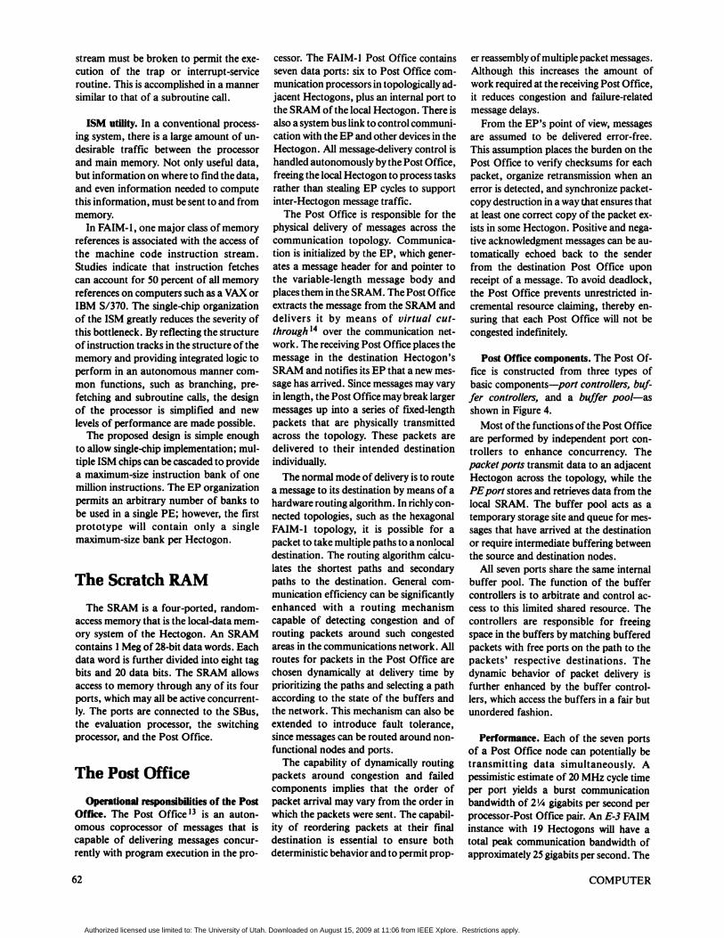
The Post OfficeOperational responsibilities of the Post
Office. The Post Office13 is an auton-omous coprocessor of messages that iscapable of delivering messages concur-rently with program execution in the pro-
cessor. The FAIM-1 Post Office containsseven data ports: six to Post Office com-munication processors in topologically ad-jacent Hectogons, plus an internal port tothe SRAM of the local Hectogon. There isalso a system bus link to control communi-cation with the EP and other devices in theHectogon. All message-delivery control ishandled autonomously by the Post Office,freeing the local Hectogon to process tasksrather than stealing EP cycles to supportinter-Hectogon message traffic.The Post Office is responsible for the
physical delivery of messages across thecommunication topology. Communica-tion is initialized by the EP, which gener-ates a message header for and pointer tothe variable-length message body andplaces them in the SRAM. The Post Officeextracts the message from the SRAM anddelivers it by means of virtual cut-through14 over the communication net-work. The receiving Post Office places themessage in the destination Hectogon'sSRAM and notifies its EP that a new mes-sage has arrived. Since messages may varyin length, the Post Office may break largermessages up into a series of fixed-lengthpackets that are physically transmittedacross the topology. These packets aredelivered to their intended destinationindividually.The normal mode of delivery is to route
a message to its destination by means of ahardware routing algorithm. In richly con-nected topologies, such as the hexagonalFAIM-l topology, it is possible for apacket to take multiple paths to a nonlocaldestination. The routing algorithm calcu-lates the shortest paths and secondarypaths to the destination. General com-munication efficiency can be significantlyenhanced with a routing mechanismcapable of detecting congestion and ofrouting packets around such congestedareas in the communications network. Allroutes for packets in the Post Office arechosen dynamically at delivery time byprioritizing the paths and selecting a pathaccording to the state of the buffers andthe network. This mechanism can also beextended to introduce fault tolerance,since messages can be routed around non-functional nodes and ports.The capability of dynamically routing
packets around congestion and failedcomponents implies that the order ofpacket arrival may vary from the order inwhich the packets were sent. The capabil-ity of reordering packets at their finaldestination is essential to ensure bothdeterministic behavior and to permit prop-
er reassembly ofmultiple packet messages.Although this increases the amount ofwork required at the receiving Post Office,it reduces congestion and failure-relatedmessage delays.From the EP's point of view, messages
are assumed to be delivered error-free.This assumption places the burden on thePost Office to verify checksums for eachpacket, organize retransmission when anerror is detected, and synchronize packet-copy destruction in a way that ensures thatat least one correct copy of the packet ex-ists in some Hectogon. Positive and nega-tive acknowledgment messages can be au-tomatically echoed back to the senderfrom the destination Post Office uponreceipt of a message. To avoid deadlock,the Post Office prevents unrestricted in-cremental resource claiming, thereby en-suring that each Post Office will not becongested indefinitely.
Post Office components. The Post Of-fice is constructed from three types ofbasic components-port controllers, buf-fer controllers, and a buffer pool-asshown in Figure 4.Most of the functions of the Post Office
are performed by independent port con-trollers to enhance concurrency. Thepacket ports transmit data to an adjacentHectogon across the topology, while thePEport stores and retrieves data from thelocal SRAM. The buffer pool acts as atemporary storage site and queue for mes-sages that have arrived at the destinationor require intermediate buffering betweenthe source and destination nodes.
All seven ports share the same internalbuffer pool. The function of the buffercontrollers is to arbitrate and control ac-cess to this limited shared resource. Thecontrollers are responsible for freeingspace in the buffers by matching bufferedpackets with free ports on the path to thepackets' respective destinations. Thedynamic behavior of packet delivery isfurther enhanced by the buffer control-lers, which access the buffers in a fair butunordered fashion.
Performance. Each of the seven portsof a Post Office node can potentially betransmitting data simultaneously. Apessimistic estimate of 20 MHz cycle timeper port yields a burst communicationbandwidth of 2 4gigabits per second perprocessor-Post Office pair. An E-3 FAIMinstance with 19 Hectogons will have atotal peak communication bandwidth ofapproximately 25 gigabits per second. The
COMPUTER62
Authorized licensed use limited to: The University of Utah. Downloaded on August 15, 2009 at 11:06 from IEEE Xplore. Restrictions apply.
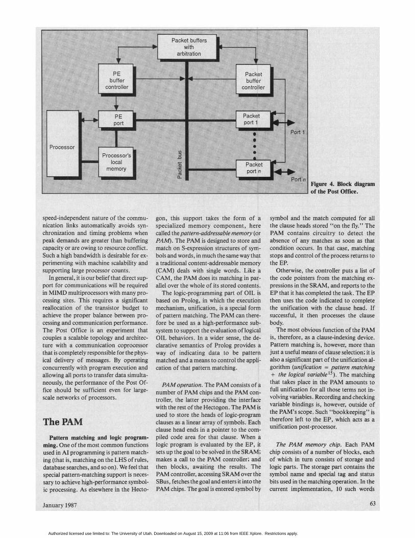
Figure 4. Block diagramof the Post Office.
speed-independent nature of the commu-nication links automatically avoids syn-chronization and timing problems whenpeak demands are greater than bufferingcapacity or are owing to resource conflict.Such a high bandwidth is desirable for ex-perimenting with machine scalability andsupporting large processor counts.
In general, it is our belief that direct sup-port for communications will be requiredin MIMD multiprocessors with many pro-cessing sites. This requires a significantreallocation of the transistor budget toachieve the proper balance between pro-cessing and communication performance.The Post Office is an experiment thatcouples a scalable topology and architec-ture with a communication coprocessorthat is completely responsible for the phys-ical delivery of messages. By operatingconcurrently with program execution andallowing all ports to transfer data simulta-neously, the performance of the Post Of-fice should be sufficient even for large-scale networks of processors.
The PAMPattern matching and logic program-
ming. One of the most common functionsused in Al programming is pattern match-ing (that is, matching on the LHS of rules,database searches, and so on). We feel thatspecial pattern-matching support is neces-sary to achieve high-performance symbol-ic processing. As elsewhere in the Hecto-
gon, this support takes the form of aspecialized memory component, herecaled thepattern-addressable memory (orPAM). The PAM is designed to store andmatch on S-expression structures of sym-bols and words, in much the same way thata traditional content-addressable memory(CAM) deals with single words. Like aCAM, the PAM does its matching in par-allel over the whole of its stored contents.The logic-programming part of OIL is
based on Prolog, in which the executionmechanism, unification, is a special formof pattern matching. The PAM can there-fore be used as a high-performance sub-system to support the evaluation of logicalOIL behaviors. In a wider sense, the de-clarative semantics of Prolog provides away of indicating data to be patternmatched and a means to control the appli-cation of that pattern matching.
PAM operation. The PAM consists ofanumber of PAM chips and the PAM con-troller, the latter providing the interfacewith the rest of the Hectogon. The PAM isused to store the heads of logic-programclauses as a linear array of symbols. Eachclause head ends in a pointer to the com-piled code area for that clause. When alogic program is evaluated by the EP, itsets up the goal to be solved in the SRAM;makes a call to the PAM controller; andthen blocks, awaiting the results. ThePAM controller, accessing SRAM over theSBus, fetches the goal and enters it into thePAM chips. The goal is entered symbol by
symbol and the match computed for allthe clause heads stored "on the fly.," ThePAM contains circuitry to detect theabsence of any matches as soon as thatcondition occurs. In that case, matchingstops and control of the process returns tothe EP.
Otherwise, the controller puts a list ofthe code pointers from the matching ex-pressions in the SRAM, and reports to theEP that it has completed the task. The EPthen uses the code indicated to completethe unification with the clause head. Ifsuccessful, it then processes the clausebody.
The most obvious function of the PAMis, therefore, as a clause-indexing device.Pattern matching is, however, more thanjust a useful means of clause selection; it isalso a significant part of the unification al-gorithm (unification = pattern matching+ the logical variable15). The matchinigthat takes place in the PAM amounts tofull unification for all those terms not in-volving variables. Recording and checkingvariable bindings is, however, outside ofthe PAM's scope. Such "bookkeeping" istherefore left to the EP, which acts as aunification post-processor.
The PAM memory chip. Each PAMchip consists of a number of blocks, eachof which in turn consists of storage andlogic parts. The storage part contains thesymbol name and special tag and statusbits used in the matching operation. In thecurrent implementation, 10 such words
January 1987 63
Authorized licensed use limited to: The University of Utah. Downloaded on August 15, 2009 at 11:06 from IEEE Xplore. Restrictions apply.

Figure 5. PAM floor plan.
are stored for every "match" section oflogic. In effect, this logic is multiplexedover the storage so as to achieve a work-able memory density.The logic part consists of comparators
for the name fields and small finite-statemachines operating on the tags to performthe matching function. Fifty-six of theseblocks are included on each PAM chip, asshown in Figure 5.The chip contains 560 words of 16-bit
symbols. If an average clause head has asize of seven PAM words, one chip canstore 80 such expressions. ThePAM chip isdesigned so that the controller can run anumber of them together and in parallelwithout the need for "glue" logic. In thisway, the total capacity of the PAM is onlylimited by the number of chips used. Ow-ing to its parallel operation, the speed ofthe matching function is independent ofthe PAM's size.
W* r e have presented an overview ofthe physical architecture of a
VVw novel, high-performance, sym-bolic multiprocessing system known asFAIM-1. A small-scale prototype of
FAIM-I that consists of a single E-3 sur-face (19 PEs) is under construction. Theprimary performance mechanism is the ex-ploitatioh of concurrency at all levels ofthe system. From the top, the FAIM-I ap-pears as a medium-grain, homogeneousmultiprocessor. The topology scales topermit an arbitrary number of processingelements to be interconnected. Each pro-cessing element can be viewed from thebottom as a heterogeneous, shared-memory multiprocessor containing ser-vers that are specialized to perform mes-sage delivery, mock-unification, datastorage and delivery, instruction storageand delivery, instruction evaluation, andrapid context switching.The architecture takes advantage of ad-
vanced circuit and packaging technologyas a secondary performance enhancernentmechanism. The present small-scale pro-totype is being implemented with customCMOS VLSI circuits (the Post Office,PAM, and ISM subsystems) and commer-cially available components (the processorand SRAM). The 19-PE initial prototypewill be attached to a host Symbolics LispMachine. The programming environ-ment, OIL compiler, resource allocator,
debugging tools, and a complete systemsimulator that can be used for initial appli-cation development all run on the Hostmachine. All of these characteristics willenable the FAIM-1 prototype to serve as asymbolic acceleratoi to the host LispMachine.While the architecture represents a
novel and significant reallocation of theconventional transistor budget so as toprovide high performance and efficientevaluation of highly concurrent symbolicprogranis, the programming environmentdeparts from conventional Al programdevelopment systems only minimally so asto incorporate concurrent application de-velopment. This eliminates the need to re-educate programmers, and it means thatthe architecture can be scaled to providetwo to three orders of magnitude perfor-mance improvement over conventional Almachines. D
References1. C. L. Seitz, Introduction to VLSI Systems,
"System Timing" (Chapter 7), McGraw-Hill,New York, 1979.
2. W. E Clocksin and C. S. Mellish, Programmingin Prolog, Springer-Verlag, New York, 1981.
3. J. A. Rees, N. 1. Adams, and J. R. Meehan,"The T Manual," technical report, 4th ed., YaleUniversity, Computer Science Dept., NewHaven, Conn., 1984.
4. J. S. Conery and P. F. Kibler, "ParallelInterpretation of Logic Programs," in Proc.Conf. Functional Programming Languages andComputer Architectures, ACM, Oct. 1981, pp.163-170.
5. D. DeGroot, "Restricted AND-Parallelism,"Proc. Int' Conf. on Fifth-Generation ComputerSystems, Nov. 1984, pp. 471-478.
6. C. L. Seitz, "The Cosmic Cube," Comm.ACM, Vol. 28, No. 1, Jan. 1984, pp. 22-33.
7. R. Gurwitz, "The Butterfly Multiprocessor,"talk presented at the 1984 ACM National Con-vention, San Francisco, Oct. 1984; also, "But-terfly Patallel Processor Overview," BBNLaboratories, Inc., 10 Moulton St., Camnbridge,MA 02238, Dec. 18, 1985.
8. S. J. Stolfo, D. Miranker, and D. E. Shaw, "Ar-chitecture and Applications ofDADO, A Large-Scale Parallel Computer for Artificial In-telligence," Proc. Eighth Int'l Joint Conf.Artificial Intelligence, Karlsruhe, West Ger-many, Aug. 1983, pp. 850-854.
9. D. P. Siewiorek and R. S. Swarz, The Theoryand Practice ofReliable System Design, DigitalPress, Bedford, Mass., 1982.
10. D. Gordon, 1. Koren, and G. M. Silberman,"Fault-Tolerance in VLSI Hexagonal Arrays,"technical report, Dept. of Electrical Ehgineer-ing, Computer Science Technion, Haifa 32000,Israel, 1984.
11. John L. Hennessy, "VLSI Processor Architec-ture," IEEE Trans. Computers, Vol. C-33, No.12, Dec. 1984, pp. 1221-1246.
12. B. W. Lampson, G. McDaniel, and S. M. Om-stein, "An Instruction Fetch Unit for a High-Performance Personal Computer," IEEETrans. Computers, Vol. C-33, No. 8, Aug. 1984,pp. 712-730.
COMPUTER64
Authorized licensed use limited to: The University of Utah. Downloaded on August 15, 2009 at 11:06 from IEEE Xplore. Restrictions apply.

13. K. S. Stevens, S. V. Robison, and A. L. Davis,"The Post Office-Communication Supportfor Distributed Ensemble Architectures," Proc.Sixth Int'l Conf. Distributed ComputingSystems, May 1986, pp. 160-167.
14. P. Kermani and L. Kleinrock, "Virtual Cut-Through: A New Computer CommunicationSwitching Technique," Computer Networks,Vol. 3, 1979, pp. 267-286.
15. D. Warren, "Implemneting Prolog," TechnicalReort 39, Edinbutgh University, May 1977.
Selected bibliographyDavis, A. L., and S. V Robison, "The Ar-chitecture of the FAIM-1 SymbolicMultiprocessing System,"Proc. Ninth IntlJoirtt Conf. Artifcirl Intelligence, Aug. 1985,pp. 32-38.Goldberg, A., and D. Robson, Smalltalk-80The Language and its Implementation,Addison-Wesley, Reading, Mass., May 1983.Kluge, W. E., and K. Lautenbauch, "TheOrderly Resolution of Memory Access Con-flicts Among Competing Channel Processes,"IEEE Trans. Computers, Vol C-31, No. 3,Mar. 1982, pp. 194-207.Lee, J. K. F, and A. J. Smith, "BranchPrediction Strategies and Branch Target BufferDesign," Computer, Vol. It, No. 1, Jan. 1984,pp. 6-22.Lyon, R. E, "Single Instruction Stream,Multiple Data Stream, Multiple Port PipelinedProcessor," Schlumberger intenal report,Schlumberger Palo Alto Research, 3340Hiliview Ave., Palo Alto, CA 94304, Sept.1985.Martin, A. J., "The Torus: An Exercise inConstructing a Surface," Proc. SecondCaltech Conf. VLSI, Jan. 1981, pp. 527-538.Przybylski, S. A., et al., "Organization andVLSI Implementation of MIPS," J. VLSI andComputing Systems, Vol. 1, No. 3, Fall 1984,pp. 170-208.Transputer INMOS Limited, "IMS T424Transputer Reference Manual," Whitefriars,Lewins Mead, Bristol, England, UK, 1984.
Judy Anderson is a memnber of the researchstaff of the Al Architectures Group at Schlum-berger Palo Alto Research. She received a BAin philosophy in 1983 and an MS in computerscience in 1984, both from Stanford University.
Wlliasm S. Coates joined the Al ArchitecturesGroup at Schlumberger Palo Alto Research in1984. He received his BS in computer science in1980, and an MS in computer science in 1985,both from the University of Calgary, Alberta,Canada.
A. L. Davis received a BS in electrical engi-neering from MIT in 1969, and a PhD in electri-cal engineering and compUter science from theUniversity of Utah in 1972. He is currently amember of the Al Architectures Group atSchlumberger Palo Alto Research. He is amember of IEEE.
Robert W. Hon is a member of the Al Architec-tures Group at Schlumberger Palo AltoResearch. Prior to joining Schiumberger, hewas an assistant professor of computer scienceat Columbia University. He holds a BS in elec-trical engineering from Yale University and gnMS and PhD in computer science from Car-negie Mellon University. He is a member ofIEEE and ACM.
lan N. Robinson is a member of the Al Archi-tectures Group at Schlumberger's Palo AltoResearch Center. He received a BSc degree inphysics with electronics from the University ofSussex, England, in 1979.
Shane V. Robison is a member of the Al Ar-chitectures Group at Schlumberger's Palo AltoResearch Center. He received his BS and MSdegrees in computer science from the Universityof Utah, Salt Lake City, Utah, in 1980 and1983, respectively. He is a member of IEEE,ACM, and AAAI.
Kenneth S. Stevens is a member of the researchstaff of the Al Architectures Group atSchlumberger Palo Alto Research. He receiveda BA degree in biology in 1982, and BS and MSdegrees in computer science in 1982 and 1984from the University of Utah. He is a member ofIEEE.
Readers may write to Shane V. Robison at Schlumberger Palo Alto Research, 3340 Hillview Ave., Palo Alto, CA 94304.
65January 1987
Authorized licensed use limited to: The University of Utah. Downloaded on August 15, 2009 at 11:06 from IEEE Xplore. Restrictions apply.