architecture of quality imaging - ahra: the association for medical imaging …€¦ · ·...
TRANSCRIPT
2 GE 2013 Architecture of Quality Imaging
DOC1292532 9/26/2014
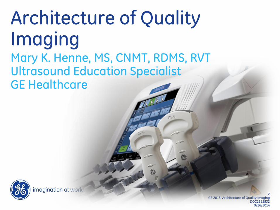
Architecture of Quality Imaging Mary K. Henne, MS, CNMT, RDMS, RVT Ultrasound Education Specialist GE Healthcare
3 GE 2013 Architecture of Quality Imaging
9/26/2014
3 GE 2013 Architecture of Quality Imaging
9/26/2014
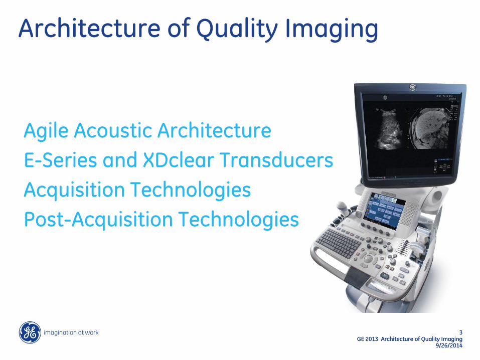
Architecture of Quality Imaging
Agile Acoustic Architecture
E-Series and XDclear Transducers
Acquisition Technologies
Post-Acquisition Technologies

4 GE 2013 Architecture of Quality Imaging
9/26/2014
Agile Acoustic Architecture

5 GE 2013 Architecture of Quality Imaging
9/26/2014
Agile Acoustic Architecture Designed to help meet the challenges of healthcare
Increasing obesity
Aging population
More difficult-to-image patients
6 GE 2013 Architecture of Quality Imaging
9/26/2014
6 GE 2013 Architecture of Quality Imaging
9/26/2014
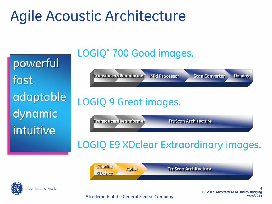
powerful
fast
adaptable
dynamic
intuitive
LOGIQ 9 Great images.
Agile Acoustic Architecture
LOGIQ* 700 Good images.
LOGIQ E9 XDclear Extraordinary images.
TruScan Architecture Agile E Series
XDclear
Mid Processor Scan Converter Beamformer Transducers Display
TruScan Architecture Beamformer Transducers
*Trademark of the General Electric Company
7 GE 2013 Architecture of Quality Imaging
9/26/2014
7 GE 2013 Architecture of Quality Imaging
9/26/2014
Agile Acoustic Architecture
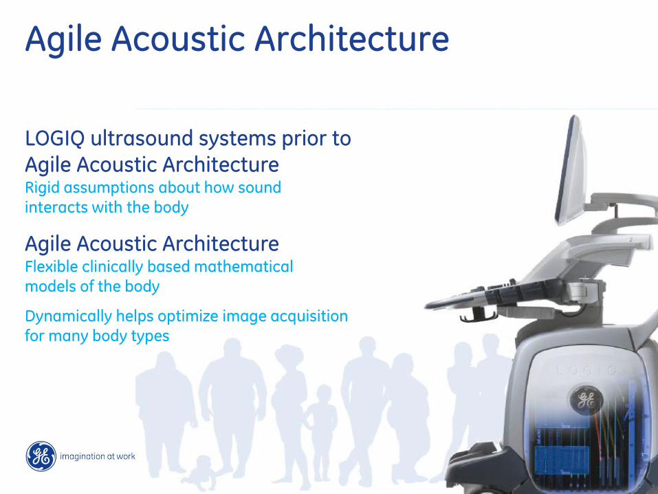
LOGIQ ultrasound systems prior to Agile Acoustic Architecture Rigid assumptions about how sound
interacts with the body
Agile Acoustic Architecture Flexible clinically based mathematical models of the body
Dynamically helps optimize image acquisition for many body types
8 GE 2013 Architecture of Quality Imaging
9/26/2014
8 GE 2013 Architecture of Quality Imaging
9/26/2014
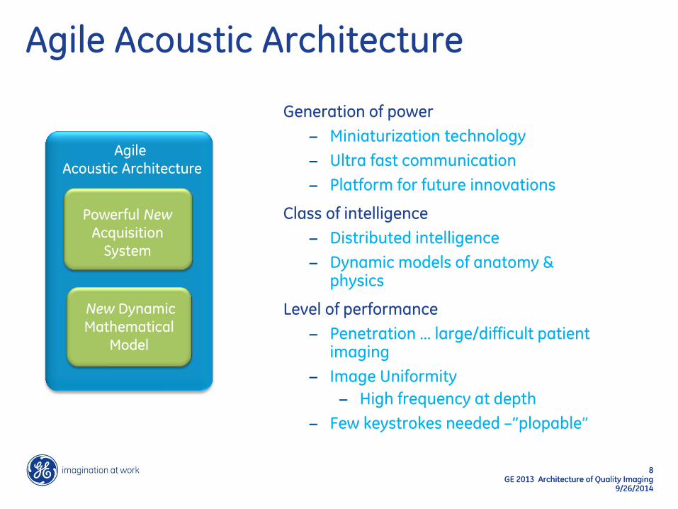
Agile Acoustic Architecture
Generation of power
− Miniaturization technology
− Ultra fast communication
− Platform for future innovations
Class of intelligence
− Distributed intelligence
− Dynamic models of anatomy & physics
Level of performance
− Penetration … large/difficult patient imaging
− Image Uniformity
− High frequency at depth
− Few keystrokes needed –”plopable”
Powerful New
Acquisition
System
New Dynamic
Mathematical
Model
Agile
Acoustic Architecture
9 GE 2013 Architecture of Quality Imaging
9/26/2014
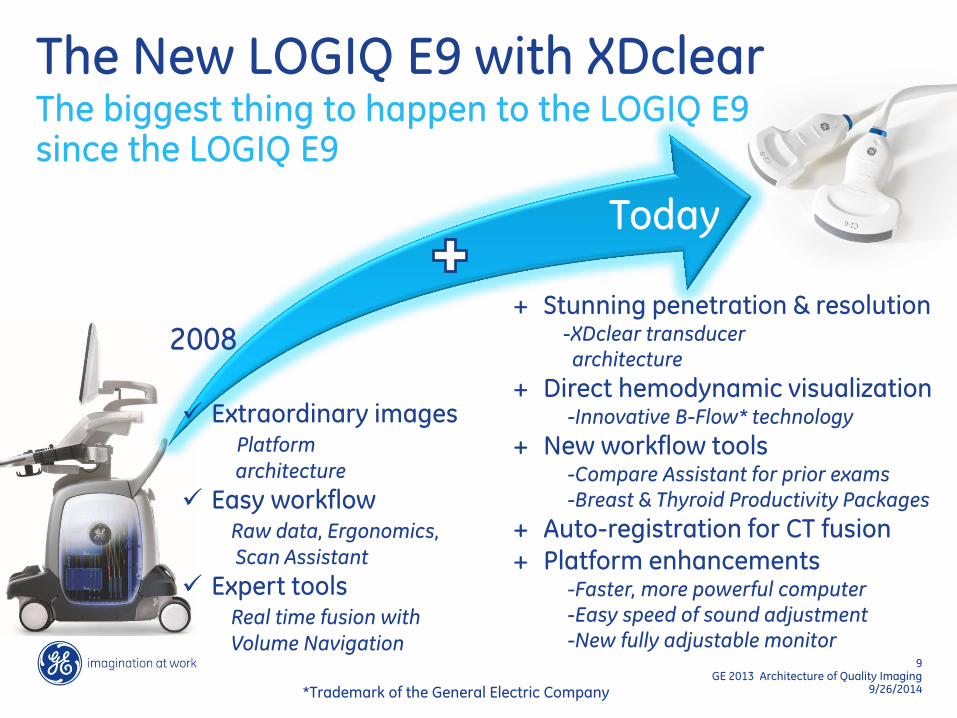
The New LOGIQ E9 with XDclear The biggest thing to happen to the LOGIQ E9 since the LOGIQ E9
Extraordinary images Platform
architecture
Easy workflow Raw data, Ergonomics,
Scan Assistant
Expert tools Real time fusion with
Volume Navigation
+ Stunning penetration & resolution -XDclear transducer
architecture
+ Direct hemodynamic visualization -Innovative B-Flow* technology
+ New workflow tools -Compare Assistant for prior exams
-Breast & Thyroid Productivity Packages
+ Auto-registration for CT fusion + Platform enhancements
-Faster, more powerful computer
-Easy speed of sound adjustment
-New fully adjustable monitor
2008
Today
*Trademark of the General Electric Company
10 GE 2013 Architecture of Quality Imaging
9/26/2014
10 GE 2013 Architecture of Quality Imaging
9/26/2014
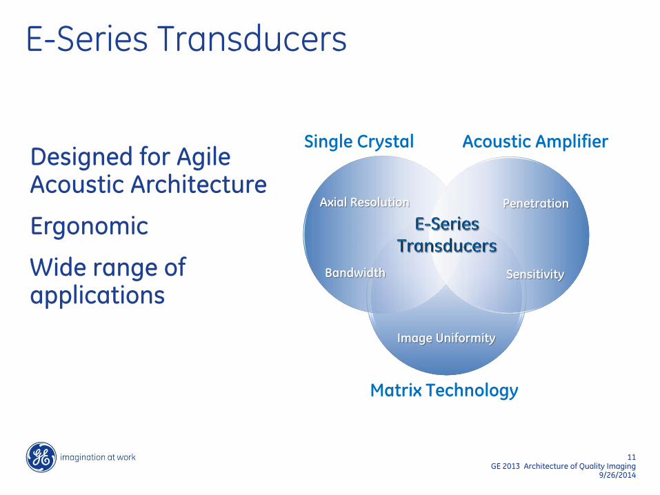
E-Series Transducers
11 GE 2013 Architecture of Quality Imaging
9/26/2014
Matrix Technology
Image Uniformity
Single Crystal
Axial Resolution
Bandwidth
Acoustic Amplifier
Penetration
Sensitivity
Designed for Agile Acoustic Architecture
Ergonomic
Wide range of applications
E-Series Transducers

13 GE 2013 Architecture of Quality Imaging
9/26/2014
Using GE‘s Single Crystal Technology helps to:
• Enhance bandwidth
• Enhance signal-to-noise ratio
• Enhance axial resolution and penetration
compared to GE‘s traditional PZT
E-Series Transducers Single crystal technology
Single Crystal exhibits enhanced dipole alignment
GE Traditional PZT Technology
The variations of polarization in PZT affect its
piezoelectric properties and signal to noise
ratio
A single crystal material exhibits fewer
poling variations than those made from multiple crystals
GE Single Crystal Technology
The electric dipoles of PZT are randomly
oriented introducing signal noise
14 GE 2013 Architecture of Quality Imaging
9/26/2014
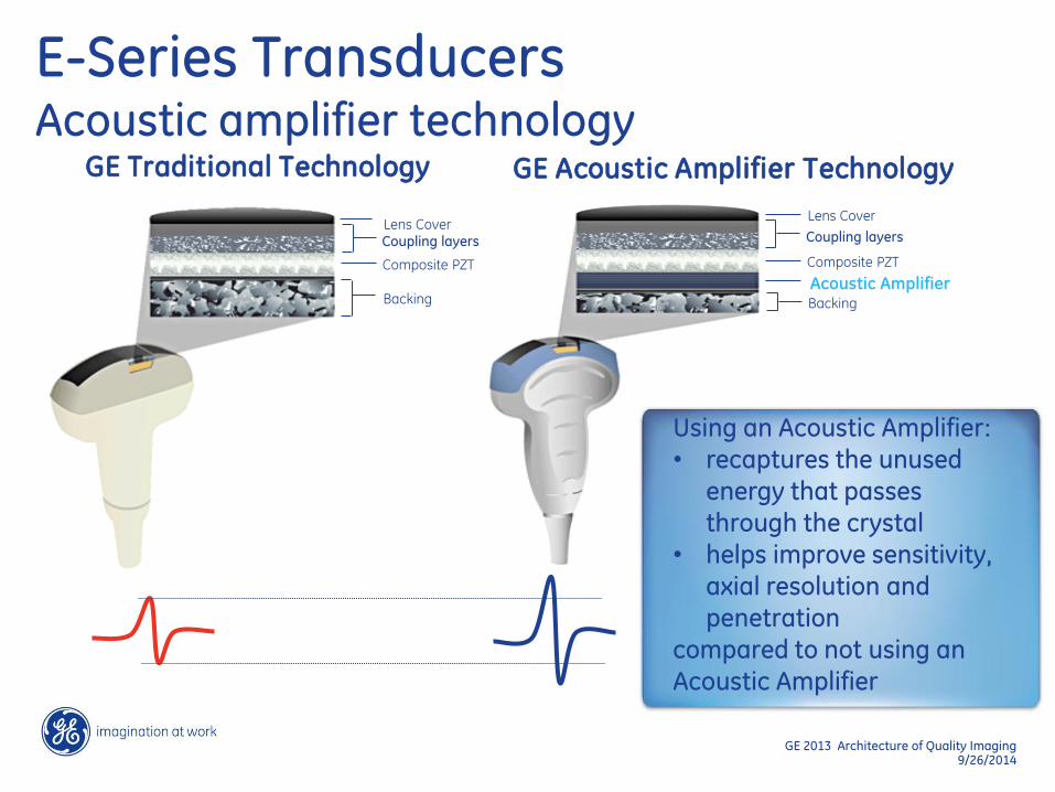
Lens Cover
Backing
Coupling layers
Composite PZT
Lens Cover
Acoustic Amplifier
Coupling layers
Composite PZT
Backing
GE Acoustic Amplifier Technology GE Traditional Technology
Using an Acoustic Amplifier: • recaptures the unused
energy that passes through the crystal
• helps improve sensitivity, axial resolution and penetration
compared to not using an
Acoustic Amplifier
E-Series Transducers Acoustic amplifier technology
15 GE 2013 Architecture of Quality Imaging
9/26/2014
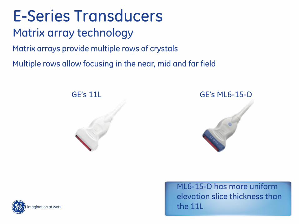
E-Series Transducers Matrix array technology
Matrix arrays provide multiple rows of crystals
Multiple rows allow focusing in the near, mid and far field
GE’s 11L GE’s ML6-15-D
ML6-15-D has more uniform elevation slice thickness than the 11L
18 GE 2013 Architecture of Quality Imaging
9/26/2014
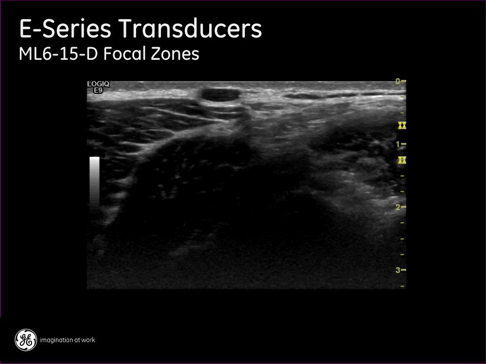
E-Series Transducers ML6-15-D Focal Zones
Focal zone above 2 cm
– Only center row used
– Narrow slice thickness for small vessels and cystic clarity
Focal zone below 2 – 2.5 cm
– All rows turned on
– Provides penetration, reduces far field noise
Models are set to use multiple zones spaced widely to ensure that appropriate number of rows are used
19 GE 2013 Architecture of Quality Imaging
9/26/2014
E-Series Transducers ML6-15-D Focal Zones
20 GE 2013 Architecture of Quality Imaging
9/26/2014
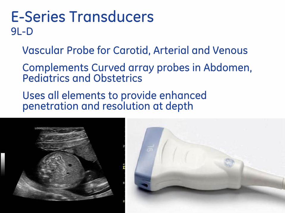
E-Series Transducers 9L-D
Vascular Probe for Carotid, Arterial and Venous
Complements Curved array probes in Abdomen, Pediatrics and Obstetrics
Uses all elements to provide enhanced penetration and resolution at depth

21 GE 2013 Architecture of Quality Imaging
9/26/2014
E-Series Transducers
9L-D Vascular OB - 16 weeks
22 GE 2013 Architecture of Quality Imaging
9/26/2014
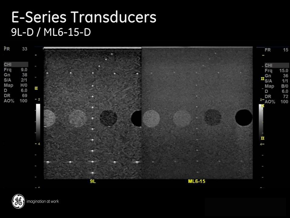
E-Series Transducers 9L-D / ML6-15-D

23 GE 2013 Architecture of Quality Imaging
9/26/2014
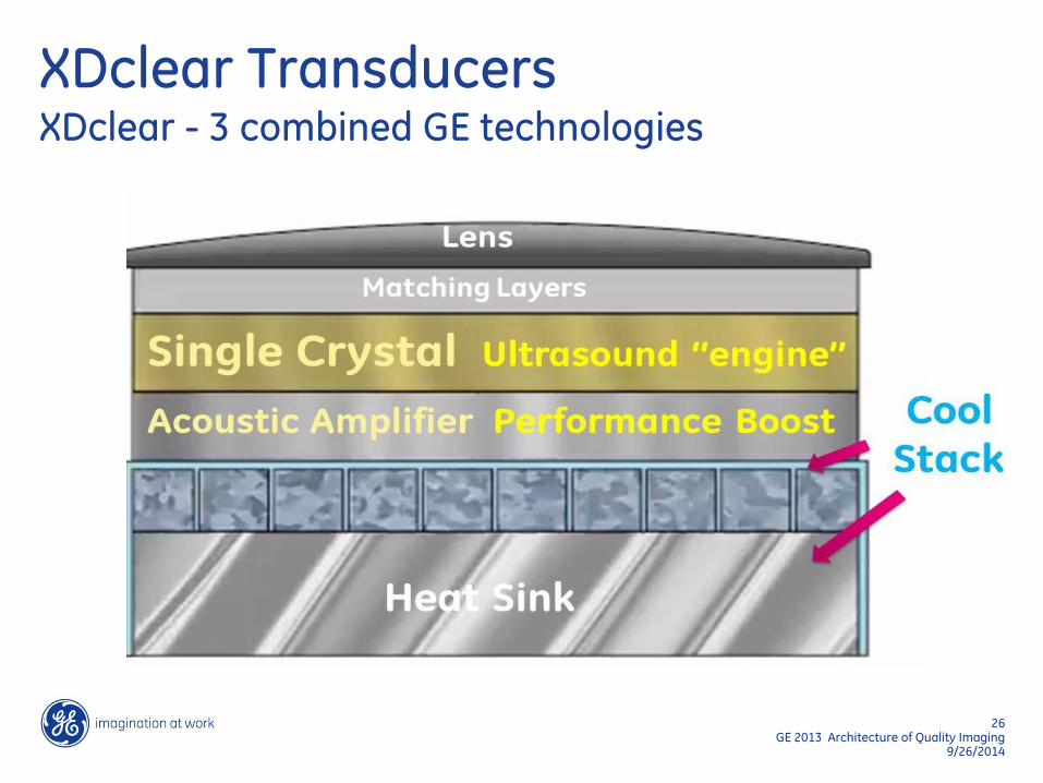
Cool Stack
Penetration Sensitivity Bandwidth
Single Crystal
Axial Resolution
Bandwidth
Acoustic Amplifier
Penetration
Sensitivity
Matrix Technology
Image Uniformity
E-Series Transducers XDclear transducers
25 GE 2013 Architecture of Quality Imaging
9/26/2014
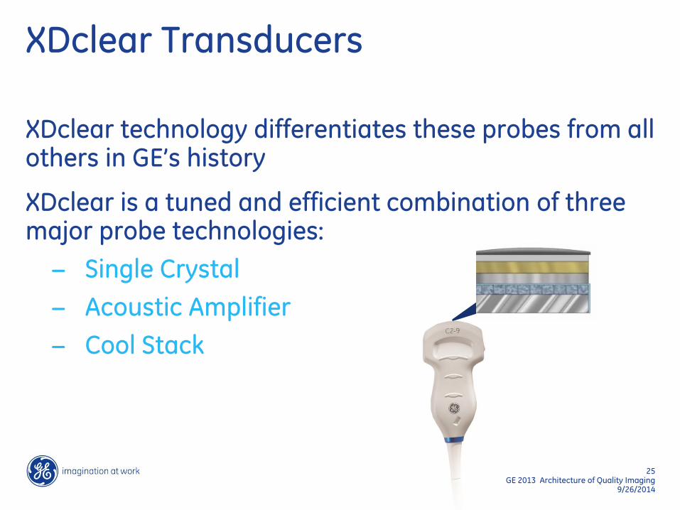
XDclear Transducers
XDclear technology differentiates these probes from all others in GE’s history
XDclear is a tuned and efficient combination of three major probe technologies:
− Single Crystal
− Acoustic Amplifier
− Cool Stack
26 GE 2013 Architecture of Quality Imaging
9/26/2014
Matching Layers
Heat Sink
XDclear Transducers XDclear - 3 combined GE technologies
27 GE 2013 Architecture of Quality Imaging
9/26/2014
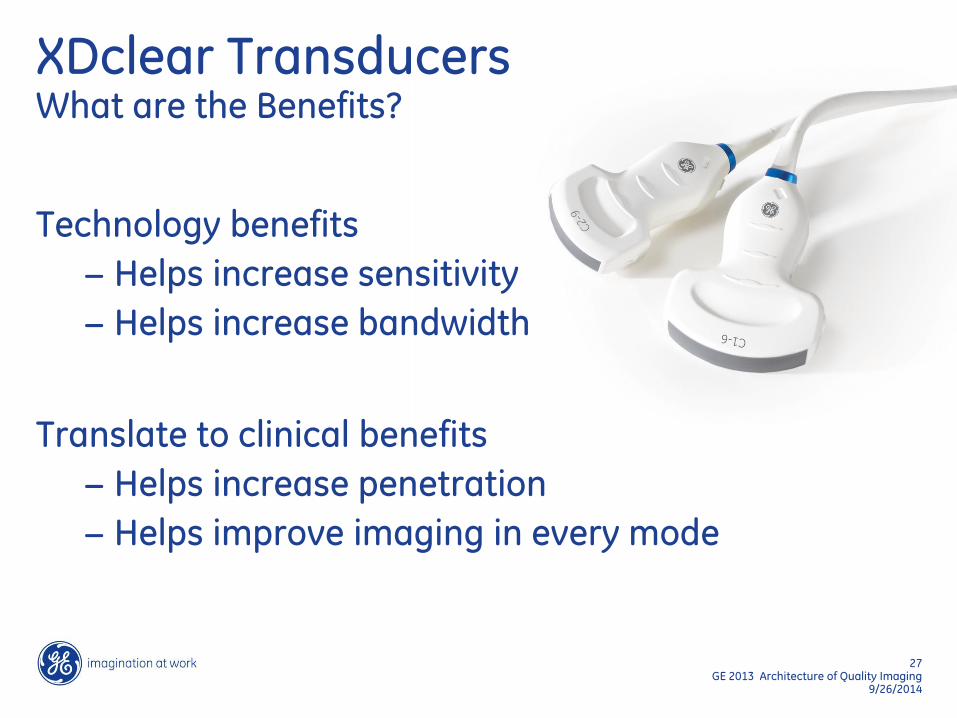
XDclear Transducers What are the Benefits?
Technology benefits
− Helps increase sensitivity
− Helps increase bandwidth
Translate to clinical benefits
− Helps increase penetration
− Helps improve imaging in every mode
28 GE 2013 Architecture of Quality Imaging
9/26/2014
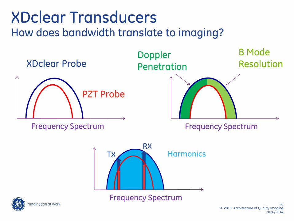
XDclear Transducers How does bandwidth translate to imaging?
XDclear Probe
PZT Probe
Frequency Spectrum
Frequency Spectrum
Harmonics TX RX
Frequency Spectrum
Doppler Penetration
B Mode Resolution
29 GE 2013 Architecture of Quality Imaging
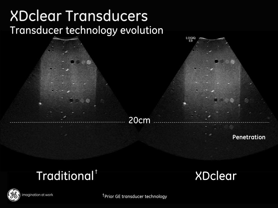
9/26/2014 Prior GE transducer technology
Traditional XDclear
20cm
Penetration
†
†
XDclear Transducers Transducer technology evolution
DOC1231114
31 GE 2013 Architecture of Quality Imaging
9/26/2014
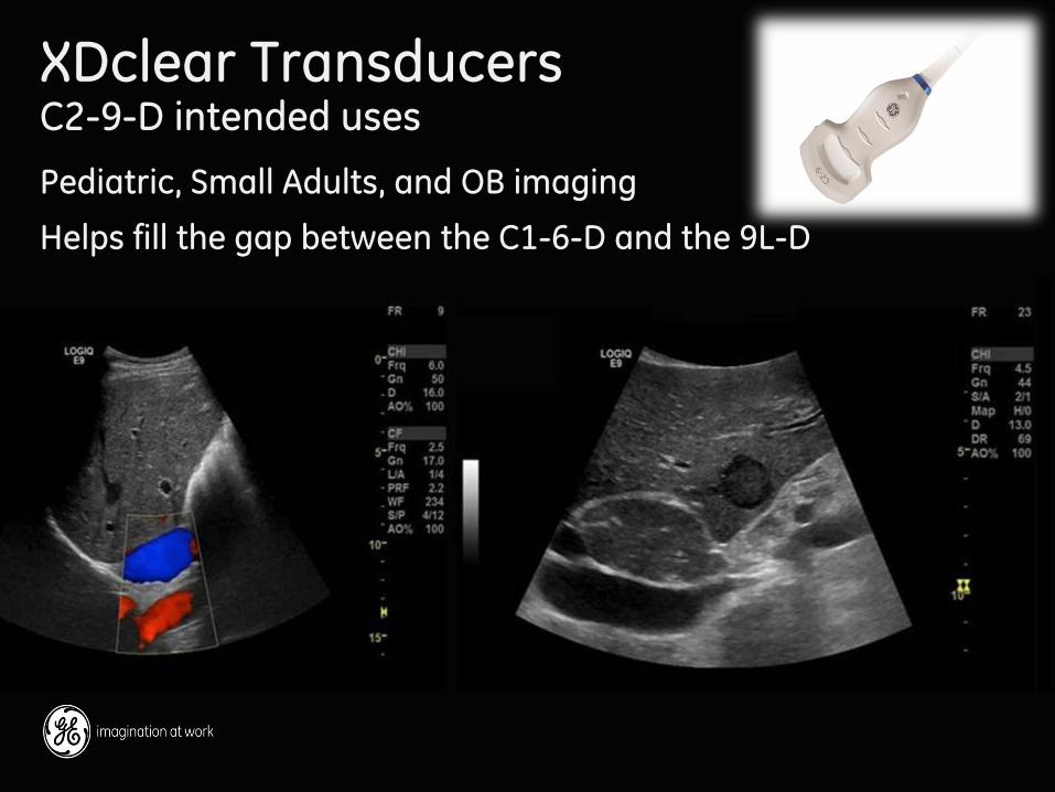
XDclear Transducers C2-9-D intended uses
Pediatric, Small Adults, and OB imaging
Helps fill the gap between the C1-6-D and the 9L-D
32 GE 2013 Architecture of Quality Imaging
9/26/2014
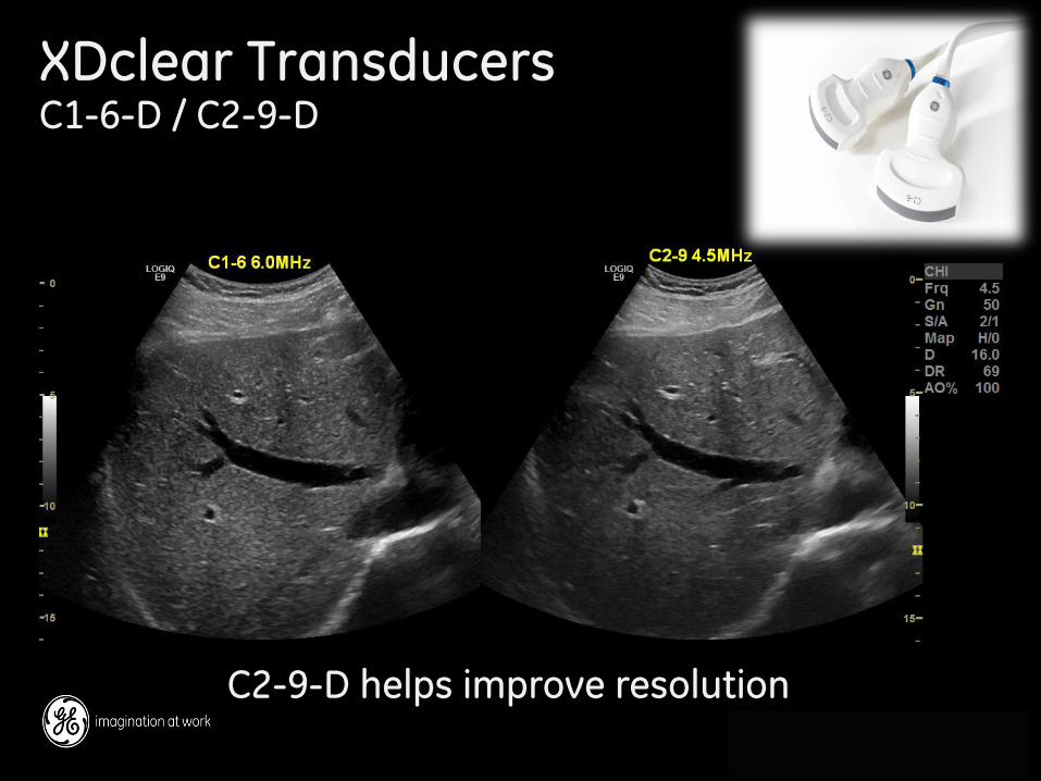
XDclear Transducers C1-6-D / C2-9-D
C2-9-D helps improve resolution
33 GE 2013 Architecture of Quality Imaging
9/26/2014
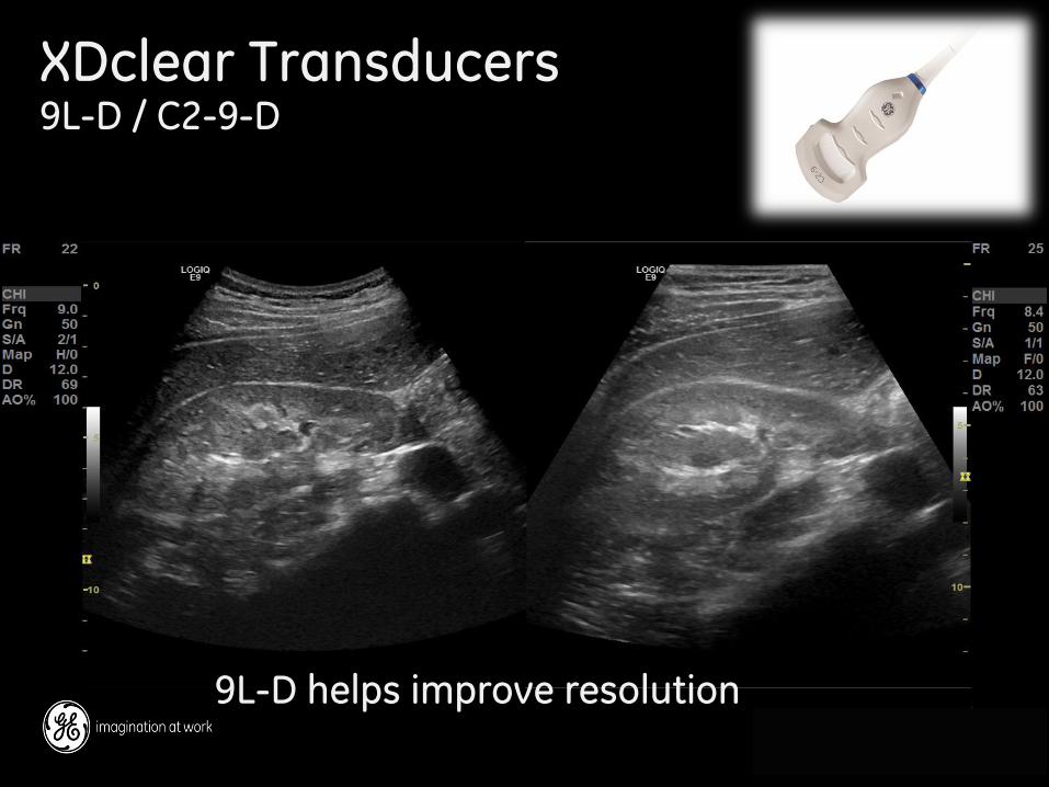
XDclear Transducers 9L-D / C2-9-D
9L-D helps improve resolution
37 GE 2013 Architecture of Quality Imaging
9/26/2014
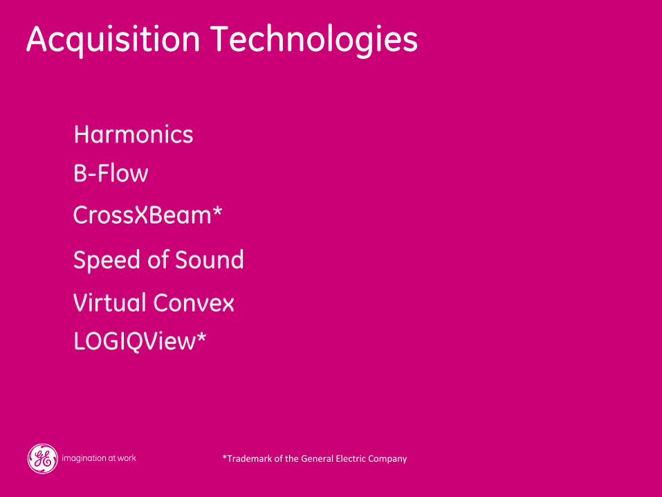
Acquisition Technologies
Harmonics
CrossXBeam*
Virtual Convex
LOGIQView*
Speed of Sound
B-Flow
*Trademark of the General Electric Company
39 GE 2013 Architecture of Quality Imaging
9/26/2014
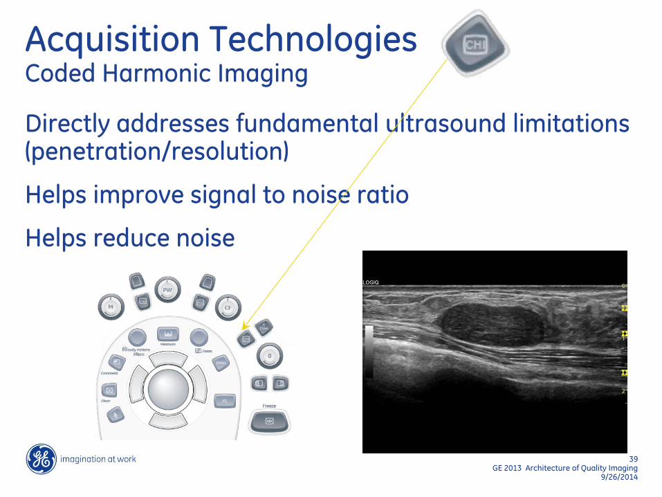
Acquisition Technologies Coded Harmonic Imaging
Directly addresses fundamental ultrasound limitations (penetration/resolution)
Helps improve signal to noise ratio
Helps reduce noise
40 GE 2013 Architecture of Quality Imaging
9/26/2014
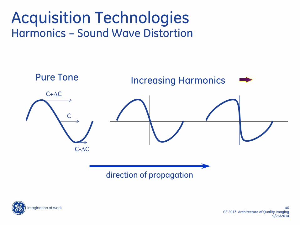
direction of propagation
C+DC
Pure Tone Increasing Harmonics
C-DC
C
Acquisition Technologies Harmonics – Sound Wave Distortion

41 GE 2013 Architecture of Quality Imaging
9/26/2014
Acquisition Technologies Harmonics
A 3.0 MHz signal that would produce maximum penetration will return a Harmonics frequency of 6.0 MHz
This returning high frequency signal only has to travel one direction (back to the probe)
The displayed image now benefits from the attributes of high frequency and a one-way travel effect

43 GE 2013 Architecture of Quality Imaging
9/26/2014
Acquisition Technologies 9L-D with and without harmonics
44 GE 2013 Architecture of Quality Imaging
9/26/2014
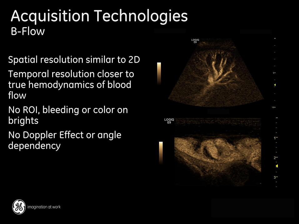
Acquisition Technologies B-Flow
Spatial resolution similar to 2D
Temporal resolution closer to true hemodynamics of blood flow
No ROI, bleeding or color on brights
No Doppler Effect or angle dependency

45 GE 2013 Architecture of Quality Imaging
9/26/2014
B-Flow B-Flow Color switch
Supported Probes: C1-6-D, 9L-D, ML6-15-D, L8-18i-D
Acquisition Technologies B-Flow user interface
46 GE 2013 Architecture of Quality Imaging
9/26/2014
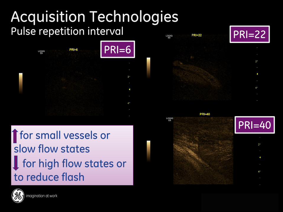
for small vessels or
slow flow states
for high flow states or
to reduce flash
PRI=6
PRI=22
PRI=40
Acquisition Technologies Pulse repetition interval
47 GE 2013 Architecture of Quality Imaging
9/26/2014
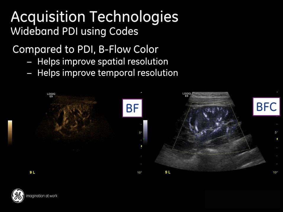
Compared to PDI, B-Flow Color − Helps improve spatial resolution − Helps improve temporal resolution
BF BFC
Acquisition Technologies Wideband PDI using Codes
48 GE 2013 Architecture of Quality Imaging
9/26/2014
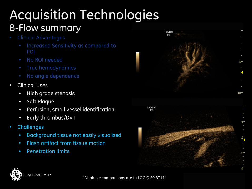
Acquisition Technologies B-Flow summary • Clinical Advantages
• Increased Sensitivity as compared to PDI
• No ROI needed
• True hemodynamics
• No angle dependence
• Clinical Uses
• High grade stenosis
• Soft Plaque
• Perfusion, small vessel identification
• Early thrombus/DVT
• Challenges
• Background tissue not easily visualized
• Flash artifact from tissue motion
• Penetration limits
“All above comparisons are to LOGIQ E9 BT11”
49 GE 2013 Architecture of Quality Imaging
9/26/2014
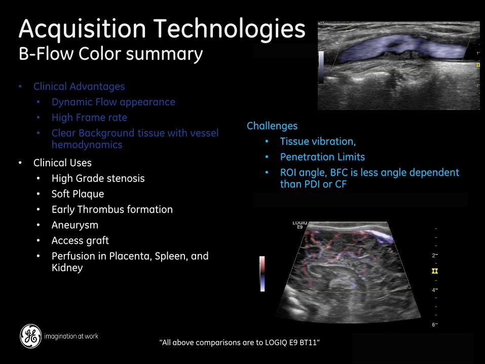
Acquisition Technologies B-Flow Color summary
• Clinical Advantages
• Dynamic Flow appearance
• High Frame rate
• Clear Background tissue with vessel hemodynamics
• Clinical Uses
• High Grade stenosis
• Soft Plaque
• Early Thrombus formation
• Aneurysm
• Access graft
• Perfusion in Placenta, Spleen, and Kidney
“All above comparisons are to LOGIQ E9 BT11”
Challenges
• Tissue vibration,
• Penetration Limits
• ROI angle, BFC is less angle dependent than PDI or CF
50 GE 2013 Architecture of Quality Imaging
9/26/2014
50 GE 2013 Architecture of Quality Imaging
9/26/2014
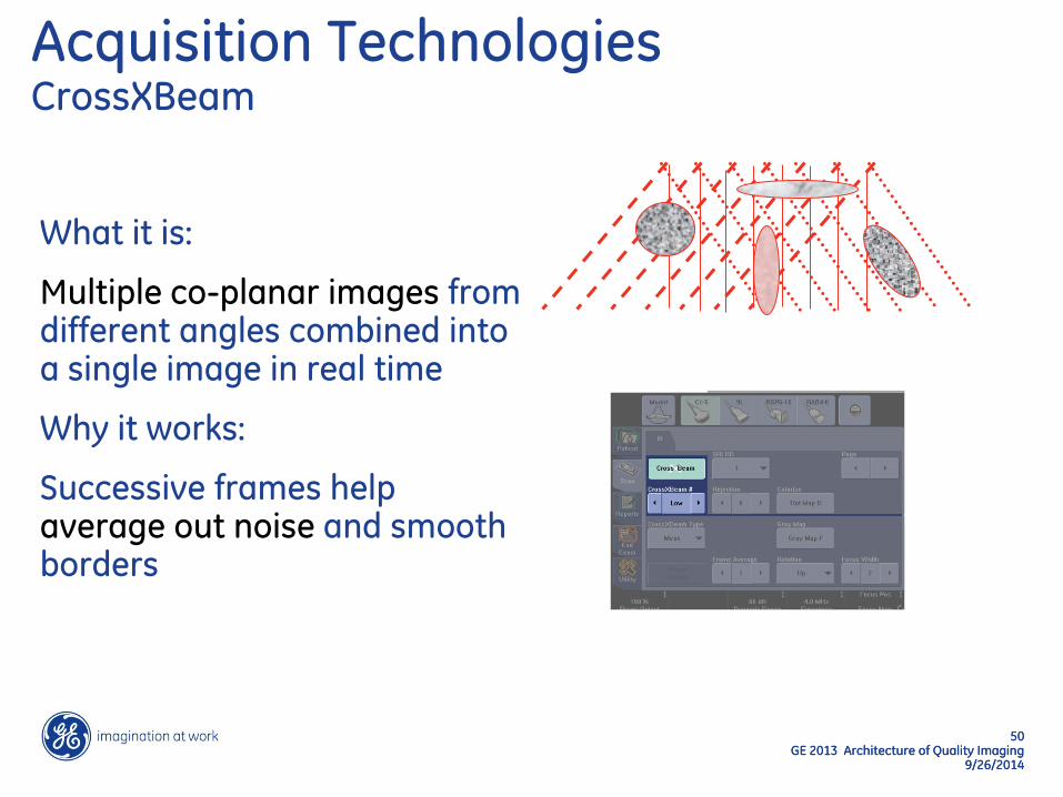
Acquisition Technologies CrossXBeam
What it is:
Multiple co-planar images from different angles combined into a single image in real time
Why it works:
Successive frames help average out noise and smooth borders
51 GE 2013 Architecture of Quality Imaging
9/26/2014
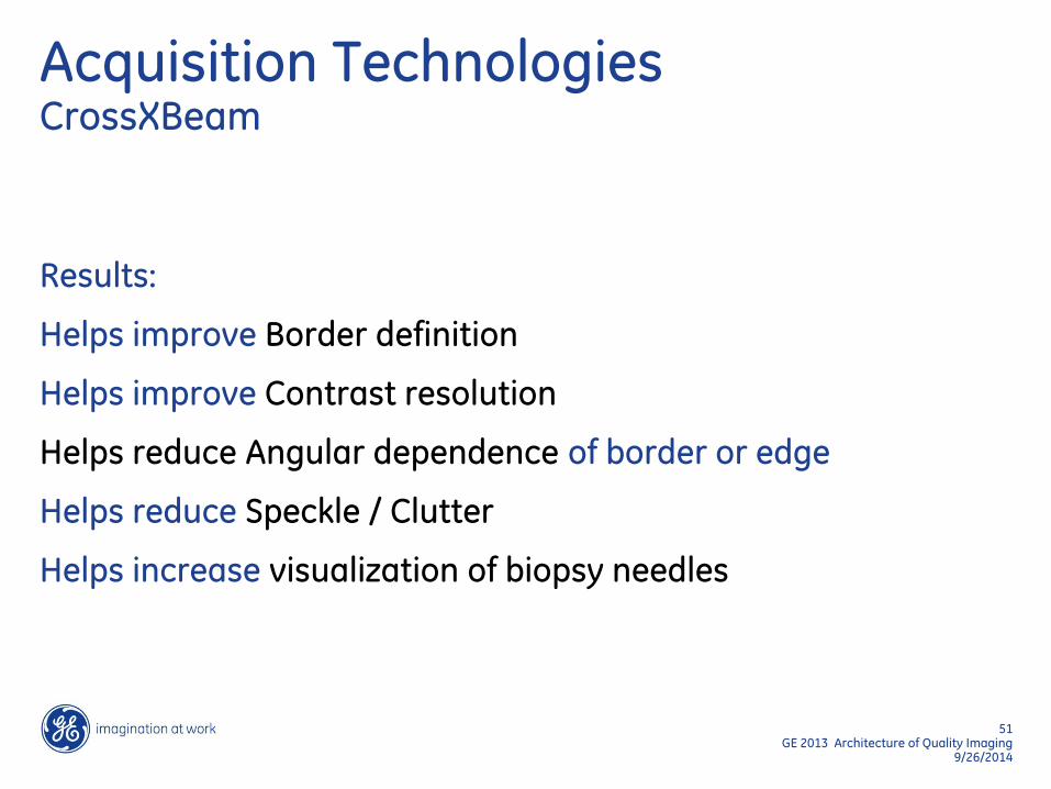
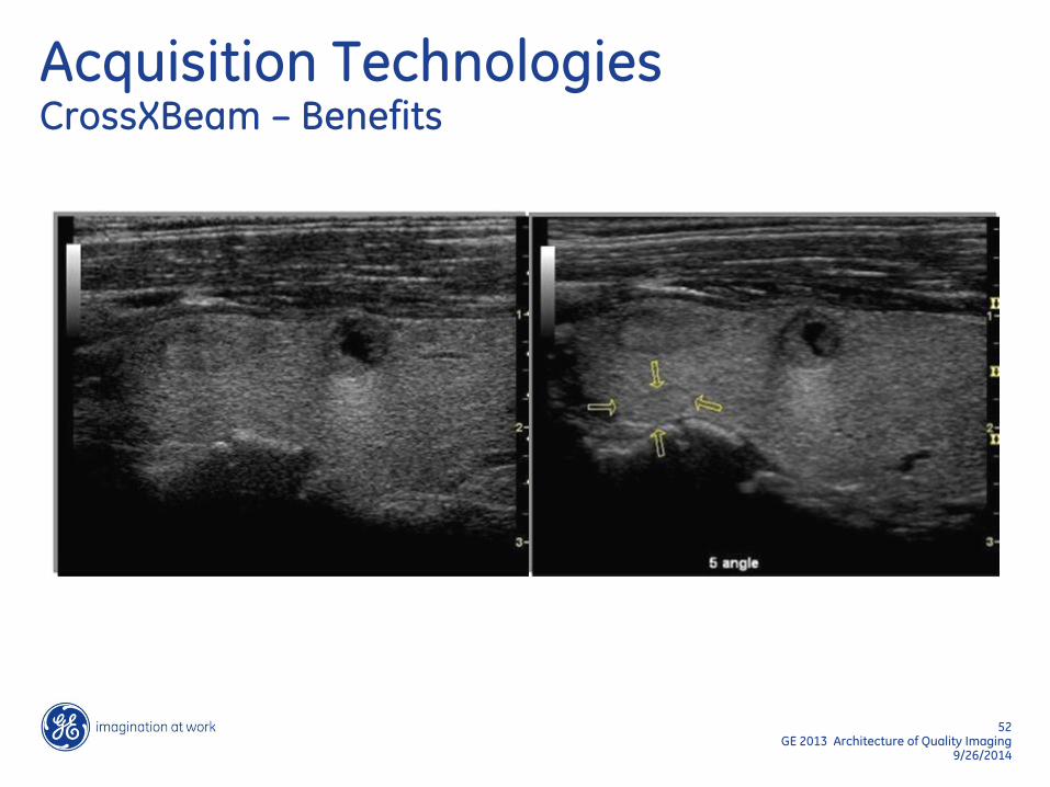
Acquisition Technologies CrossXBeam
Results:
Helps improve Border definition
Helps improve Contrast resolution
Helps reduce Angular dependence of border or edge
Helps reduce Speckle / Clutter
Helps increase visualization of biopsy needles
52 GE 2013 Architecture of Quality Imaging
9/26/2014
Acquisition Technologies CrossXBeam – Benefits
53 GE 2013 Architecture of Quality Imaging
9/26/2014
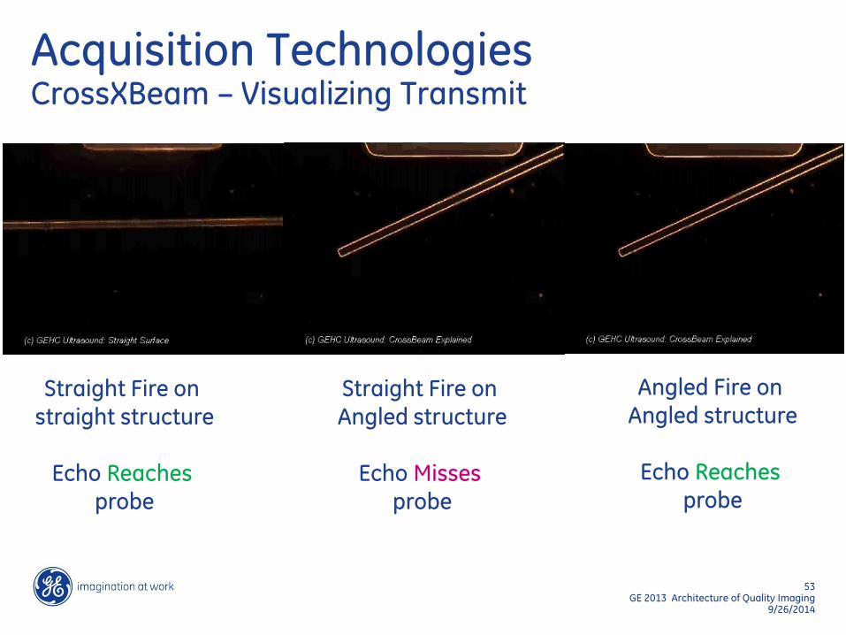
Straight Fire on straight structure
Echo Reaches
probe
Straight Fire on Angled structure
Echo Misses
probe
Angled Fire on Angled structure
Echo Reaches
probe
Acquisition Technologies CrossXBeam – Visualizing Transmit
54 GE 2013 Architecture of Quality Imaging
9/26/2014
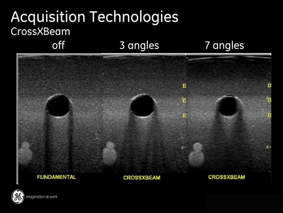
Acquisition Technologies CrossXBeam
off 3 angles 7 angles
55 GE 2013 Architecture of Quality Imaging
9/26/2014
Acquisition Technologies Speed of Sound
What it is:
An additional control to help optimize image resolution
In applications where tissue types are diverse, it allows the user to choose settings that are well suited for that particular patient
Clinical impacts:
Adjusting the speed of sound can help improve:
− Resolution
− A sharp image, especially in breast
− Signal-to-Noise
− Adjustable focusing helps improve SNR
56 GE 2013 Architecture of Quality Imaging
9/26/2014
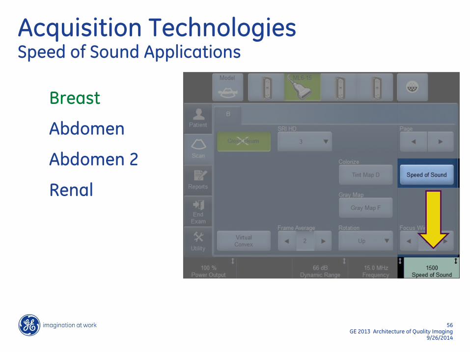
Acquisition Technologies Speed of Sound Applications
Breast
Abdomen
Abdomen 2
Renal

57 GE 2013 Architecture of Quality Imaging
9/26/2014
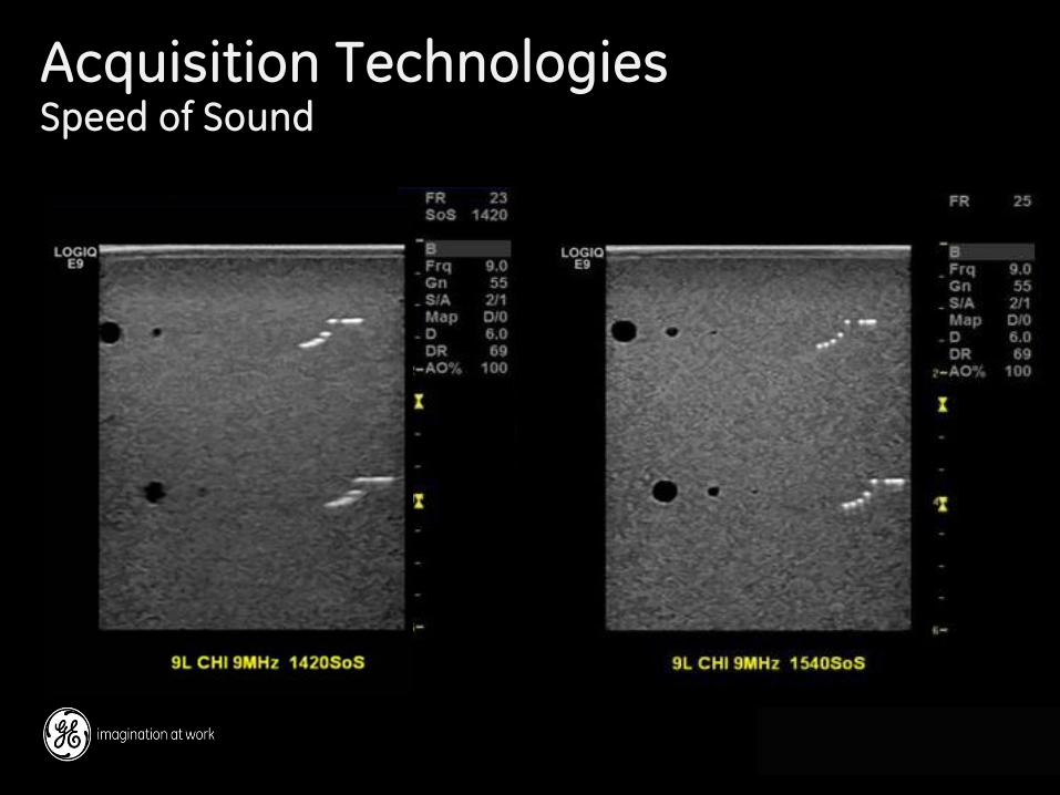
Acquisition Technologies Speed of Sound breast example 1420 m/s has enhanced contrast & resolution in this case
58 GE 2013 Architecture of Quality Imaging
9/26/2014
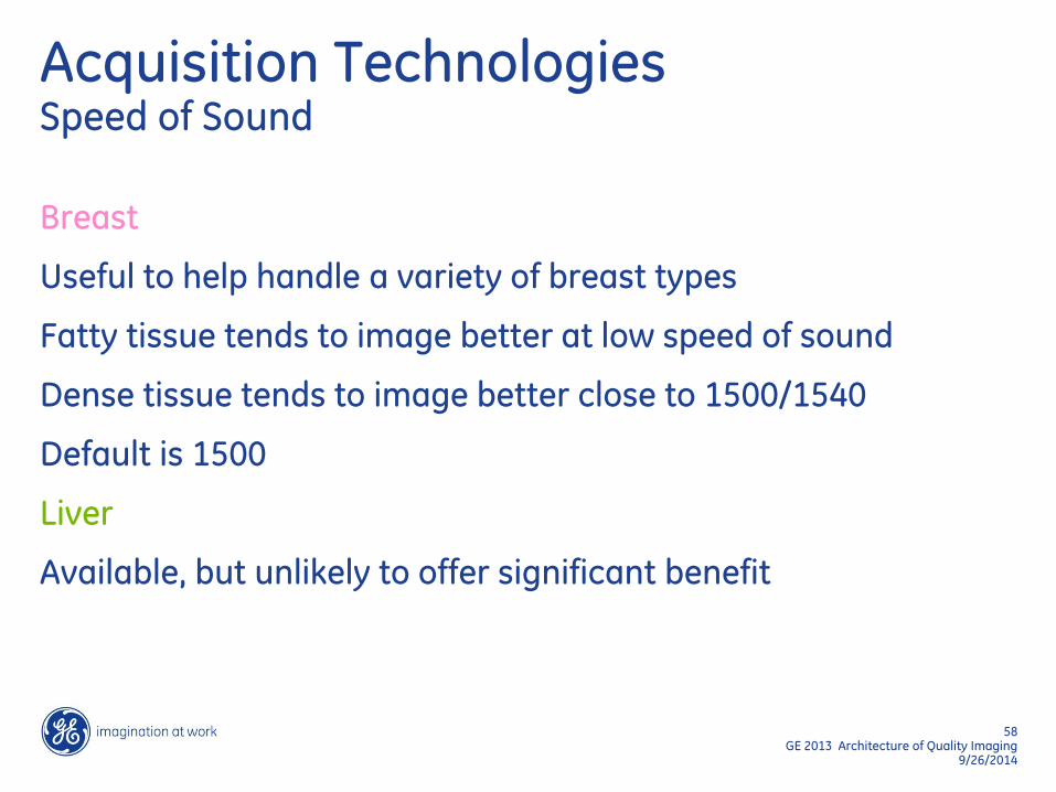
Acquisition Technologies Speed of Sound
Breast
Useful to help handle a variety of breast types
Fatty tissue tends to image better at low speed of sound
Dense tissue tends to image better close to 1500/1540
Default is 1500
Liver
Available, but unlikely to offer significant benefit
59 GE 2013 Architecture of Quality Imaging
9/26/2014
Acquisition Technologies Speed of Sound
60 GE 2013 Architecture of Quality Imaging
9/26/2014
60 GE 2013 Architecture of Quality Imaging
9/26/2014
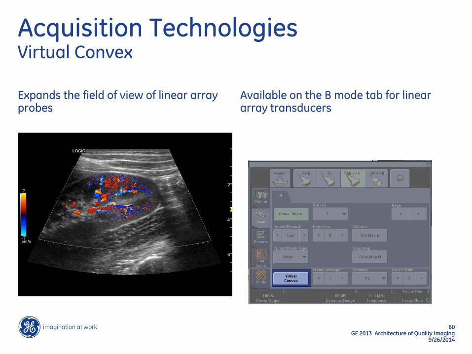
Acquisition Technologies Virtual Convex
Expands the field of view of linear array probes
Available on the B mode tab for linear array transducers

61 GE 2013 Architecture of Quality Imaging
9/26/2014
Probe Face
Field of view
Linear Probes
Linear format Virtual Apex format
Field of view
New Apex Position
Acquisition Technologies Virtual Convex
62 GE 2013 Architecture of Quality Imaging
9/26/2014
62 GE 2013 Architecture of Quality Imaging
9/26/2014
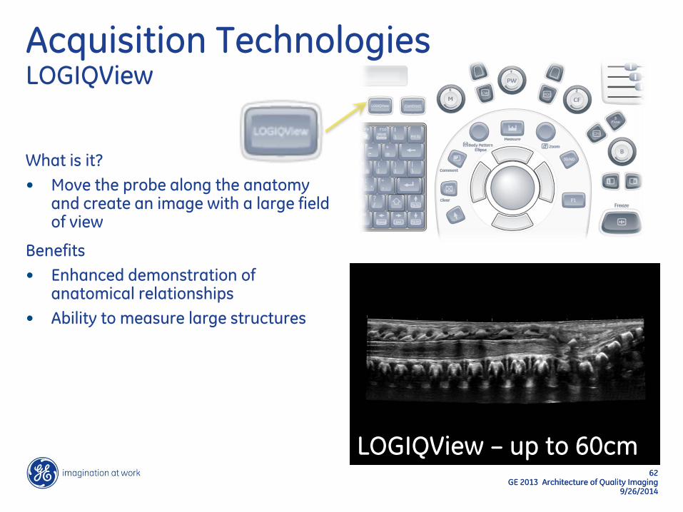
Acquisition Technologies LOGIQView
What is it?
• Move the probe along the anatomy and create an image with a large field of view
Benefits
• Enhanced demonstration of anatomical relationships
• Ability to measure large structures
LOGIQView – up to 60cm
63 GE 2013 Architecture of Quality Imaging
9/26/2014
64 GE 2013 Architecture of Quality Imaging
9/26/2014
Post-Acquisition Technologies
Raw Data
Speckle Reduction Imaging
65 GE 2013 Architecture of Quality Imaging
9/26/2014
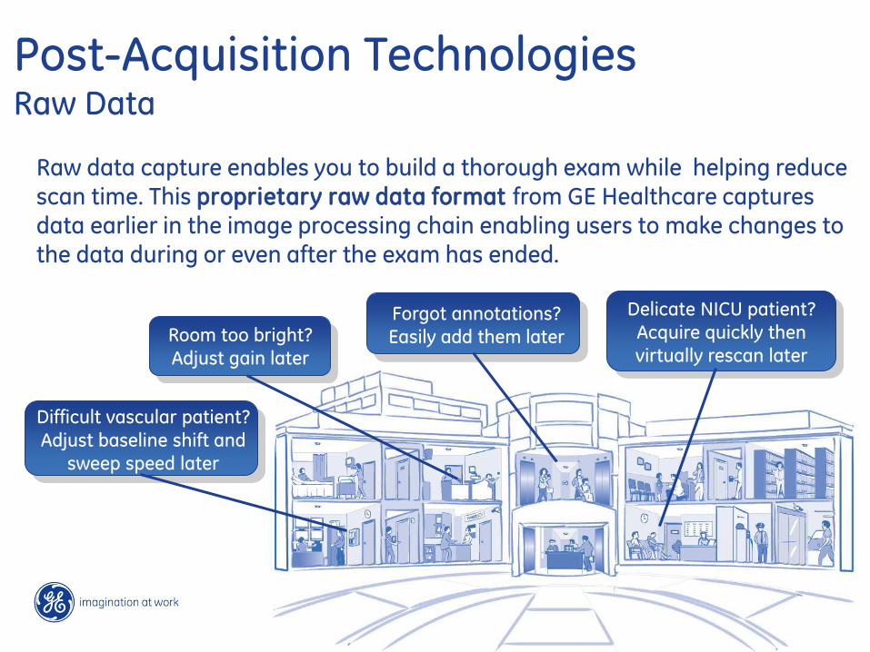
Delicate NICU patient?
Acquire quickly then
virtually rescan later
Forgot annotations?
Easily add them later
Difficult vascular patient?
Adjust baseline shift and
sweep speed later
Raw data capture enables you to build a thorough exam while helping reduce scan time. This proprietary raw data format from GE Healthcare captures data earlier in the image processing chain enabling users to make changes to the data during or even after the exam has ended.
Room too bright?
Adjust gain later
Post-Acquisition Technologies Raw Data
66 GE 2013 Architecture of Quality Imaging
9/26/2014
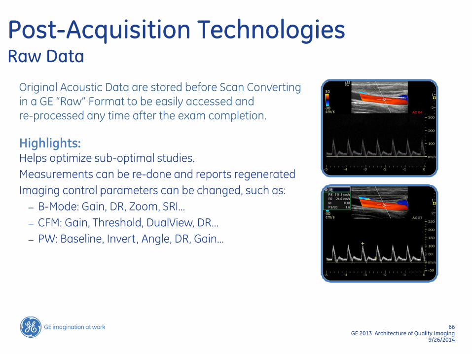
Post-Acquisition Technologies Raw Data
Original Acoustic Data are stored before Scan Converting in a GE “Raw” Format to be easily accessed and re-processed any time after the exam completion.
Highlights: Helps optimize sub-optimal studies.
Measurements can be re-done and reports regenerated
Imaging control parameters can be changed, such as:
– B-Mode: Gain, DR, Zoom, SRI…
– CFM: Gain, Threshold, DualView, DR…
– PW: Baseline, Invert, Angle, DR, Gain…
67 GE 2013 Architecture of Quality Imaging
9/26/2014
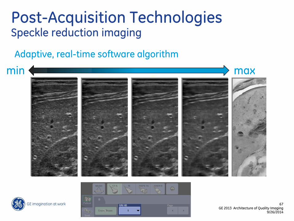
Post-Acquisition Technologies Speckle reduction imaging
Adaptive, real-time software algorithm
min max
68 GE 2013 Architecture of Quality Imaging
9/26/2014
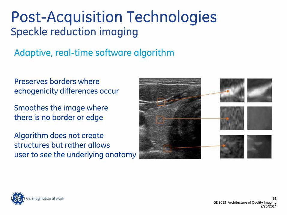
Post-Acquisition Technologies Speckle reduction imaging
Adaptive, real-time software algorithm
Preserves borders where echogenicity differences occur
Smoothes the image where there is no border or edge
Algorithm does not create structures but rather allows user to see the underlying anatomy
69 GE 2013 Architecture of Quality Imaging
9/26/2014
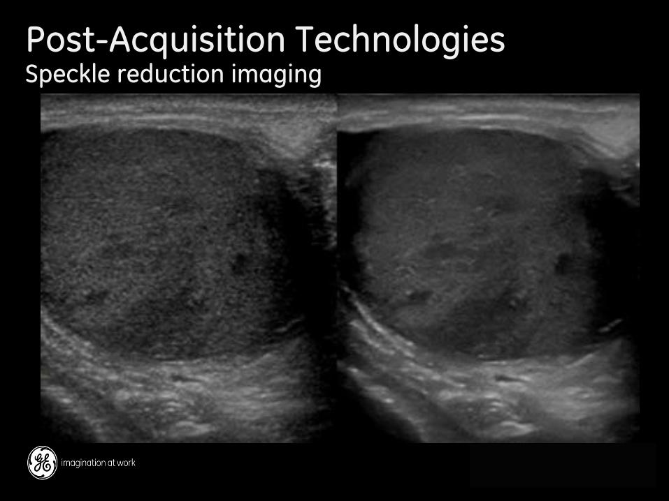
Post-Acquisition Technologies Speckle reduction imaging
71 GE 2013 Architecture of Quality Imaging
DOC1292532 9/26/2014
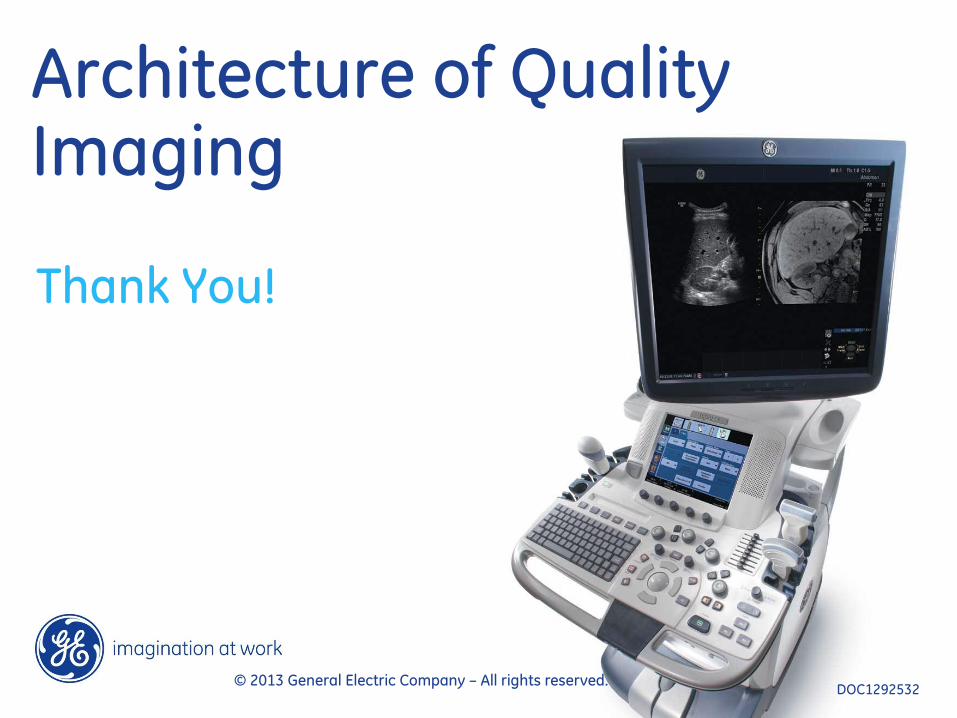
Architecture of Quality Imaging
Thank You!
© 2013 General Electric Company – All rights reserved. DOC1292532