arcsketch 1.1 user guide - esri support...
TRANSCRIPT

ArcSketch™ User Guide
for
ArcSketch™ Version 1.1
ArcSketch is a sample extension to ArcGIS. It works with ArcGIS 9.1
ArcSketch allows the user to quickly create, or “sketch,” features in ArcMap using easy-to-use drawing tools and symbols. The user simply selects a drawing tool
and an associated symbol, then draws the feature. ArcSketch automatically handles the assignment of the feature to the appropriate sketch layer.
For further information, visit
http://www.esri.com/arcsketch/
3/22/2006
2
Table of Contents Introducing ArcSketch™ 5 How to use this User Guide 5 The Basic Concept 5 Some Limitations 6 Installation and Activation 6 Installation Requirements Checking your Computer Installing Microsoft .NET Framework 1.1 Installing ESRI’s .NET Support feature for ArcGIS Installing ArcSketch Activating ArcSketch Quick Start Tutorial 9 Exercise 1: Getting Started with ArcSketch 9 Setting up your project The relationship between drawing tools and symbols Drawing markers, lines and areas Using the selection tools Editing sketch features Saving your work Exercise 2: Working with Symbols 20 Symbol graphics and properties Creating a new symbol Editing a symbol in the symbol palette Editing an undefined symbol in the symbol palette Editing a defined symbol in the drawing Editing an undefined symbol Importing symbol sets as styles Importing symbols from a layer Exercise 3: Working with Layers 29 Ordering Layers in the TOC Ordering Features in a Layer Saving Sketch Projects Saving Sketch Layers

3
User Environment 31 ArcSketch Toolbar ArcSketch Table of Contents ArcSketch Drawing Tools ArcSketch Symbol Palette ArcSketch Personal Geodatabase Using the ArcSketch Toolbar 33 Creating a New Sketch Project Opening an Existing Sketch Project Display/Close Sketch Tools Display/Close Symbol Palette Turn On/Off the Snapping Environment Using the ArcSketch Table of Contents 37 ArcSketch Directories Sketch Layers vs. Standard Map Layers Moving Layers Up and Down in the Table of Contents Using the Sketch Project Context Menu Using the Sketch Layer Context Menu Using the ArcSketch Drawing Tools 42 Selection Tools Marker Drawing Tool Line Drawing Tools Area Drawing Tools Feature Editing Tools Undo/Redo Tools Feature Transformation Tools Using the Snapping Tools 51 Using the Symbol Palette 53 Menu Bar Symbols (for markers, lines and areas) Symbol Sets Symbol Properties Current Symbols Symbol Editing Finding Symbols

4
Saving and Sharing Your Work 59 Saving a Sketch Project as Part of a Map Document Saving a Sketch Project as a Separate Layer File Saving a Symbol Set Sharing Your Sketch Project with Others Sharing Your Symbol Sets with Others Working Directly with an ArcSketch Personal Geodatabase 62 Adding Labels to ArcSketch Layers 62 Using ModelBuilder with ArcSketch 63 Creating Reports with ArcSketch 64 Technical Support 64 The ArcSketch Web Site FAQs Discussion Forum Copyright Notice 65 .
5
Introducing ArcSketch™ ArcSketch™ is a sample extension to ArcGIS. It is offered free to our users on an “as is” basis. ESRI provides no support and assumes no liability regarding its use by our customers. How to Use This User Guide ArcSketch is presented as a prototype, or exploration, of what ESRI might develop in the future. Like ArcSketch, this User Guide is somewhat of a prototype as well. Your critical review of ArcSketch is important to us. Please feel free to post your comments and suggestions regarding both ArcSketch and this User Guide on the ArcSketch project Web site at:
http://www.esri.com/arcsketch/ The following highlights have been embedded throughout this User Guide to bring attention to particular notes and cautionary comments:
Highlighted notes: Are rendered in blue Warnings and cautions: Are rendered in orange Capabilities not yet implemented: Are rendered in gray
The Basic Concept ArcSketch gives the user the ability to place a transparent “sketch” overlay (which is actually a set of sketch layers) over any number of background layers in ArcMap. The user simply selects a drawing tool and an associated symbol, then draws the feature. ArcSketch automatically handles the assignment of the feature to the appropriate sketch layer. The user does not have to manage, or even see, the individual sketch layers. As far as the user is concerned, s/he is simply drawing (sketching) features on the transparent overlay. Users can use the drawing tools in ArcSketch for drawing (sketching) three types of features: markers, lines, and areas. The user simply selects a drawing tool of a specific type, selects a corresponding symbol (of the same type of geometry as the selected drawing tool), then draws the feature. Users can select symbols from one of the many symbol sets that come with ArcSketch, from symbol sets they import into ArcSketch (either from layers or styles), or by creating their own symbols using the ArcSketch symbol editor. The basic intent underlying the development of ArcSketch is to provide the user with the ability to draw features in ArcGIS as easily as they would if they were drawing with felt-tip pens on tracing paper.

6
Some Limitations ArcSketch is a working prototype. As such, it is not a fully developed product, nor does it necessarily represent the direction ESRI might take in the future with respect to creating and editing features. ArcSketch is not supported by ESRI Technical Support. A user forum, however, has been established to assist users and to provide a venue for user feedback. Users can link to this forum from: http://www.esri.com/arcsketch/ ArcMap software’s standard Editor toolbar is closed when ArcSketch is active. This is due to the fact that ArcSketch manages its own editing environment. At least one background layer must be added to ArcMap before opening a new ArcSketch project. Sketch layers are not recognized by native ArcMap. ArcSketch must be installed in ArcMap in order for ArcMap to be able to recognize sketch layers. ArcSketch cannot directly edit standard layers. Most standard layers, however, can be imported (copied) into ArcSketch. The drawing tools in ArcSketch only work on copies of the imported layers. ArcSketch does not work with ArcSDE. Installation and Activation ArcSketch is an unsupported sample extension to the ArcMap application in ArcGIS 9.1.
Installation Requirements ArcSketch requires that one of the following version of ArcGIS be installed on your computer:
ArcGIS Desktop 9.1 with the .NET Support feature
The .NET Support feature of ArcGIS Desktop requires Microsoft’s .NET Framework 1.1.
Windows 2000 users must ensure that they have Microsoft Data Access Components (MDAC) Version 2.6 or later.

7
Checking Your Computer To check for Microsoft .NET Framework 1.1:
Go to Control Panel > Add/Remove Programs and look for Microsoft .NET Framework 1.1 in the list. If you do not find it, follow the instructions listed below for Installing Microsoft .NET Framework 1.1. Note: If you find Microsoft .NET Framework 2.0 in the list, you will still
need to install version 1.1. (Do not remove version 2.0.) To check if the ArcGIS Desktop .NET Support feature is installed:
Use Windows Explorer to navigate to the location on your hard drive where you installed ArcGIS Desktop and look for the DotNet folder. For example, go to: C:\Program Files\ArcGIS\DotNet If you do not find the DotNet folder, follow the instructions for Installing ESRI’s .NET Support feature for ArcGIS.
To check for Microsoft Data Access Components (MDAC) Version 2.6 or later:
Users can check the MDAC version they have installed by using the MDAC Utility: Component Checker.
Installing Microsoft .NET Framework 1.1 To install Microsoft .NET Framework 1.1, do the following:
Download the Microsoft .NET Framework 1.1 from Microsoft at: http://www.microsoft.com/downloads/ by clicking on the link to Developer Tools and selecting the .NET Framework Version 1.1 Redistributable Package. Follow Microsoft’s instructions for installing the package.
Installing the ArcGIS Desktop .NET Support Feature To add the .NET Support feature, you will need access to the source for ArcGIS Desktop, either on CD or via your network.
Go to Control Panel > Add/Remove Programs, select ArcGIS Desktop, and click on Change.

8
When the message window appears, either insert the ArcGIS Desktop CD into your disk drive or browse to the source on your network and click OK. When the ArcGIS Setup window appears, select Modify and click Next. Select .NET Support, click Next and follow the instructions. (A red X to the left of the .NET Support feature indicates that it is not currently installed.)
Installing ArcSketch
Caution: Before installing ArcSketch, you must first uninstall all previous versions of ArcSketch.
To use ArcSketch, you will need to download it from ESRI’s Web site, install it on your computer, then activate it from within ArcMap.
Users can download ArcSketch and the ArcSketch User Guide at:
http://www.esri.com/arcsketch/ To install ArcSketch, unzip the downloaded file, double-click on Setup.exe, and follow the instructions.
Activating ArcSketch ArcSketch is activated by clicking on View in the ArcMap menu, selecting Toolbars, then checking ArcSketch.
Note: This may take a few minutes.
Once ArcSketch has been activated, you can dock the ArcSketch toolbar to the ArcMap tool strip directly below the ArcMap menu strip.
Caution: You must add a layer to ArcMap before using ArcSketch.

9
Quick-Start Tutorial These tutorials assume ArcSketch is installed and activated in ArcMap. Exercise 1: Getting started with ArcSketch
Setting up your project: (1) Open ArcMap. (2) Add at least one background layer to ArcMap. Note: ArcSketch requires at least one background layer in ArcMap
software’s Display table of contents. The background layer provides the spatial reference for your sketch project. It also provides a visual context for your sketching.
(3) Click on Sketch Projects in the ArcMap toolbar and select New
Sketch Project. Enter the name of your project. Enter the path name indicating where your project will be saved. Enter a short description of your project. Click on Create. ArcSketch will add your sketch project to ArcMap software’s Display table of contents.
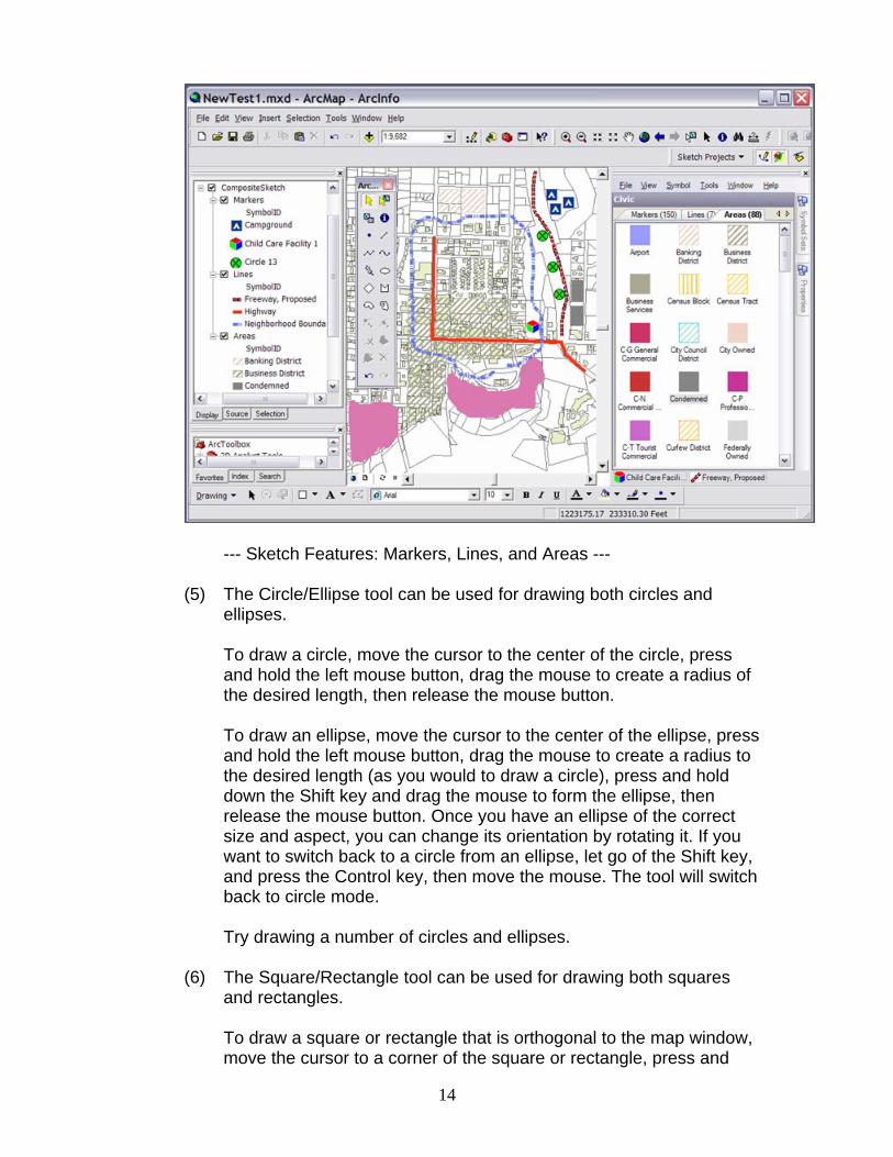
--- ArcMap with ArcSketch ---

10
(4) Click on the Sketch Tools button (to the right of the Sketch Projects drop-down menu button). This will display the ArcSketch drawing tools. You can dismiss the drawing tools by clicking on this button again.
Note: Activating the ArcSketch drawing tools automatically
deactivates ArcMap software’s Editor tools. This is done to prevent conflict between the two toolsets.
(5) Click on the Show Symbol Sets button (to the right of the Sketch
Tools button). This will display the ArcSketch symbol palette. You can dismiss the symbol palette by clicking on this button again.
The relationship between drawing tools and symbols: (1) Click on the Symbol Sets tab (on the right edge of the Symbol Palette).
Select ESRI. Double-click on the horizontal pin in the upper right corner of the palette. The ESRI marker symbols are now displayed in the palette. Click on the Lines tab to display the line symbols. Click on the Areas tab to display the area symbols.
--- Symbol Sets --- (2) Click on the point marker tool on the ArcSketch drawing toolbar. Notice
that when you did this, the symbol palette automatically displayed the marker symbols. Now experiment a bit by clicking on some of the other marker, line, and area drawing tools in the ArcSketch drawing toolbar
11
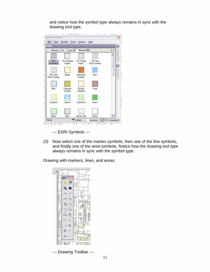
and notice how the symbol type always remains in sync with the drawing tool type.
--- ESRI Symbols --- (3) Now select one of the marker symbols, then one of the line symbols,
and finally one of the area symbols. Notice how the drawing tool type always remains in sync with the symbol type.
Drawing with markers, lines, and areas:
--- Drawing Toolbar ---
12
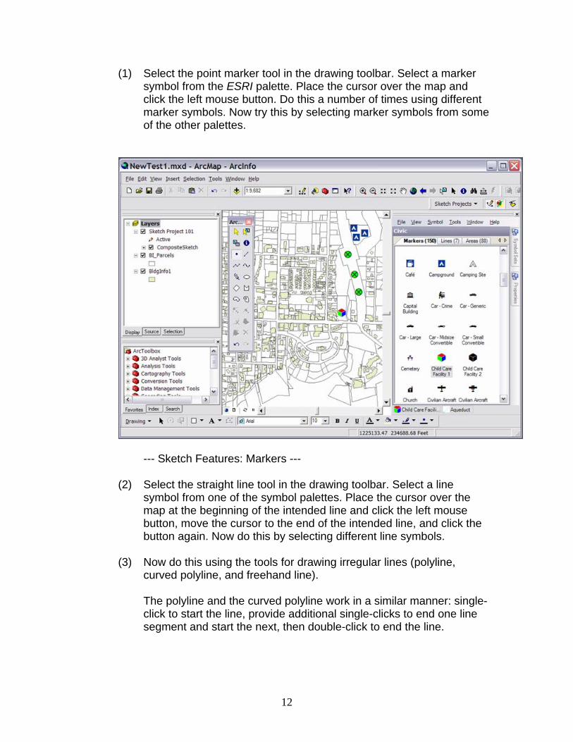
(1) Select the point marker tool in the drawing toolbar. Select a marker
symbol from the ESRI palette. Place the cursor over the map and click the left mouse button. Do this a number of times using different marker symbols. Now try this by selecting marker symbols from some of the other palettes.
--- Sketch Features: Markers --- (2) Select the straight line tool in the drawing toolbar. Select a line
symbol from one of the symbol palettes. Place the cursor over the map at the beginning of the intended line and click the left mouse button, move the cursor to the end of the intended line, and click the button again. Now do this by selecting different line symbols.
(3) Now do this using the tools for drawing irregular lines (polyline,
curved polyline, and freehand line). The polyline and the curved polyline work in a similar manner: single-
click to start the line, provide additional single-clicks to end one line segment and start the next, then double-click to end the line.

13
--- Sketch Features: Markers and Lines --- The freehand line can be drawn by single-clicking at the start of the
line, moving the cursor to create the line, then single-clicking to end the line; or by depressing the left mouse button, dragging the mouse to create the line, releasing the button.
(4) Irregular areas (created with the polygon, curved polygon, and
freehand polygon tools) are created in much the same way as are irregular lines (using the polyline, curved polyline, and freehand line tools). Try to draw some irregular areas using the polygon, curved polygon, and freehand polygon tools.
14
--- Sketch Features: Markers, Lines, and Areas --- (5) The Circle/Ellipse tool can be used for drawing both circles and
ellipses. To draw a circle, move the cursor to the center of the circle, press
and hold the left mouse button, drag the mouse to create a radius of the desired length, then release the mouse button.
To draw an ellipse, move the cursor to the center of the ellipse, press
and hold the left mouse button, drag the mouse to create a radius to the desired length (as you would to draw a circle), press and hold down the Shift key and drag the mouse to form the ellipse, then release the mouse button. Once you have an ellipse of the correct size and aspect, you can change its orientation by rotating it. If you want to switch back to a circle from an ellipse, let go of the Shift key, and press the Control key, then move the mouse. The tool will switch back to circle mode.
Try drawing a number of circles and ellipses. (6) The Square/Rectangle tool can be used for drawing both squares
and rectangles. To draw a square or rectangle that is orthogonal to the map window,
move the cursor to a corner of the square or rectangle, press and
15
hold the left mouse button, drag the mouse to create the shape of the square or rectangle, then release the mouse button.
To draw a square or rectangle that is not orthogonal to the map
window, move the cursor to either the upper left or lower right corner of the square or rectangle (depending on which corner you wish to serve as the point of rotation), press and hold the left mouse button, drag the mouse to create the shape of the square or rectangle (as you would to draw one that is orthogonal to the map window), press and hold down the Shift key and drag the mouse to rotate the shape, then release the mouse button.
Try drawing a number of squares and rectangles. Make some that
are orthogonal to the map window and some that are not. Using the Selection tools: (1) By now, you probably have more features (markers, lines, and areas)
than needed for the next few steps of this exercise, so let’s delete some of them, but not all of them. Leave a few markers, lines, and areas that we can use for the rest of this exercise.
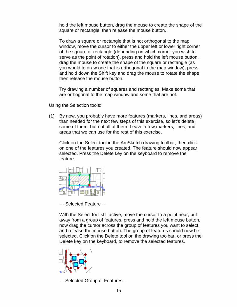
Click on the Select tool in the ArcSketch drawing toolbar, then click
on one of the features you created. The feature should now appear selected. Press the Delete key on the keyboard to remove the feature.
--- Selected Feature --- With the Select tool still active, move the cursor to a point near, but
away from a group of features, press and hold the left mouse button, now drag the cursor across the group of features you want to select, and release the mouse button. The group of features should now be selected. Click on the Delete tool on the drawing toolbar, or press the Delete key on the keyboard, to remove the selected features.
--- Selected Group of Features ---

16
(2) Click on the Select by Symbol tool in the drawing toolbar. Click on
one of the features that have the same symbol as some of the other features in the drawing. Notice that all features with the same symbol are now selected. Press the Delete key on the keyboard to remove the selected features.
--- Features Selected by Symbol --- (3) Click on the Undo tool on the drawing toolbar to bring back the
features you just deleted. Now press the Redo tool to delete them. (4) Click on the Identify tool on the drawing toolbar. Click on the drop-
down arrow to the right of the Layer Field and select the feature layer containing the feature you wish to identify. Now click on the feature to display its properties. Record its OBJECTID number.
--- Identify Dialog Box --- (5) Click on the Select by Attributes tool on the drawing toolbar to bring
up the Select by Attributes dialog box. Click on the drop-down arrow to the right of the Layer Field and select the feature layer containing the feature identified in the previous step. Use the equation construction tools in the dialog box to set the WHERE clause to read “[OBJECTID]={the OBJECTID number recorded in the previous

17
step}”. Click on the OK button. The feature identified in the previous step should now be selected. Close the Identify Results window.
--- Select by Attributes Dialog Box --- Note: This is a long way around to select a feature. The purpose of
this exercise, however, is not to show you how to select a feature you just identified but rather to show you how you can select features by their attributes.
Editing sketch features: (1) Select one of the areas (polygons) you just created. Make sure you
just have one area selected. Caution: The editing functions will not work if multiple features are
selected. The selected area should now be bounded by a rectangle with
handles on both the boundary lines and at the corners of the boundary lines. A hand is used to represent the cursor as long as it stays within the boundary rectangle. You should also notice that the feature editing tools in the drawing toolbar are now active.

18
--- Selected Feature --- Place the cursor over the feature, depress the left mouse button, and
drag the feature to a new location. Release the mouse button. Right-click on the selected feature, select Move to bring up the Delta
X-Y dialog box, type in values for both X and Y, and press the Enter key on your keyboard. The feature should move to the specified location.
--- Selected Feature Context Menu --- To duplicate a feature, simply select the feature, right-click, and
select Duplicate. To replicate a feature, select the feature, right-click to bring up the
menu, select Replicate, and type in the number of replicates you desire and press the Enter key on your keyboard.
(2) To move a feature vertex, select the feature, click on the Move
Vertex tool on the drawing toolbar, position the cursor near the vertex you wish to move, depress the left mouse button, drag the vertex to its new location, and release the button.

19
--- Move Vertex --- (3) To add a vertex, select the feature, click the Add Vertex tool, move the
cursor to the line segment where you would like to add a vertex, depress the mouse button, drag the vertex to its location, and release.
--- Add Vertex --- (4) To delete a feature vertex, select the feature, click on the Delete
Vertex tool on the drawing toolbar, position the cursor near the vertex you wish to delete, and click the left mouse button.
--- Delete Vertex --- (5) To split a feature, select the feature, click on the Split Feature tool,
single left-click to start the cut line, single left-click at all points along the cut line, then double-click at the end of the cut line.
--- Split Feature ---
20
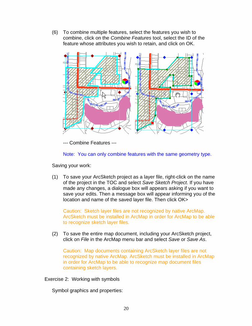
(6) To combine multiple features, select the features you wish to
combine, click on the Combine Features tool, select the ID of the feature whose attributes you wish to retain, and click on OK.
--- Combine Features --- Note: You can only combine features with the same geometry type. Saving your work: (1) To save your ArcSketch project as a layer file, right-click on the name
of the project in the TOC and select Save Sketch Project. If you have made any changes, a dialogue box will appears asking if you want to save your edits. Then a message box will appear informing you of the location and name of the saved layer file. Then click OK>
Caution: Sketch layer files are not recognized by native ArcMap.
ArcSketch must be installed in ArcMap in order for ArcMap to be able to recognize sketch layer files.
(2) To save the entire map document, including your ArcSketch project,
click on File in the ArcMap menu bar and select Save or Save As. Caution: Map documents containing ArcSketch layer files are not
recognized by native ArcMap. ArcSketch must be installed in ArcMap in order for ArcMap to be able to recognize map document files containing sketch layers.
Exercise 2: Working with symbols
Symbol graphics and properties:

21
(1) As you no doubt discovered in the previous exercise, marker symbols (points) are represented by a single graphic, lines (lines) are represented by an open stroke, and areas (polygons) are represented by a closed stroke and a fill.
Caution: Due to the fact that changes to symbols and symbol sets are recorded and saved instantaneously, it is always a good idea to back up your symbol sets before you modify them.
(2) The properties associated with each symbol type include the
symbol’s Name, Category, Description, FeatureClass, FieldName, and FieldValue. The Name, Category, and Description fields are used to define its meaning. The FeatureClass, FieldName, and FieldValue are used to define where the feature resides in the spatial data structure.
--- Symbol Properties --- Select a symbol contained in one of the symbol sets, click on the
Properties tab to the right of the symbol palette, and examine the symbol’s properties. Do this for a number of symbols.
(3) When undefined symbols (symbols undefined with respect to
FeatureClass, FieldName, and FieldValue) are used to draw features, the features are assigned to the appropriate default feature class (Markers, Lines, or Areas) in the CompositeSketch group layer.

22
--- Sketch Project TOC and Undefined Area --- Click on the Symbol Sets tab, select ESRI, double-click on the pin in
the upper right corner of the Symbol Sets selection window, click on the Areas tab, and select the Biohazard Overlay symbol. Click on the Properties tab and notice that the FeatureClass, FieldName, and FieldValue fields are blank, thus indicating that the symbol is undefined. Dismiss the Properties sheet and draw an area feature with the selected symbol. Open the CompositeSketch group layer in the Display table of contents and notice that the symbol has been added to the default Areas feature class.
(4) When a defined symbol (a symbol defined with respect to
(FeatureClass, FieldName, and FieldValue) is used to draw a feature, the feature is assigned to the feature class specified by the symbol’s properties. If the feature class (as defined by the symbol’s properties) does not exist, then one is created automatically.

23
--- Sketch Project TOC and Defined Area --- (5) Click on the Symbol Sets tab, select Land Use, click on the Areas
tab, and select the red 2000 – General Sales or Services symbol. Click on the Properties tab and notice that the FeatureClass, FieldName, and FieldValue fields are not blank, thus indicating that the symbol is defined. Dismiss the Properties sheet and draw an area feature with the selected symbol. Notice that a new feature class titled LandUse was added to the sketch project and that a symbol labeled 2000 – General Sales or Services was added to that new feature class.
Creating a new symbol: (1) Make sure the Areas tab is selected for the active symbol set. To
create a new symbol, right-click anywhere in the white space on the Areas symbol sheet and select New.
--- New Symbol ---

24
(2) Double click on the New Area Symbol. Use the Symbol Property
Editor dialog box to design the graphic representation for that symbol and click OK.
--- Symbol Property Editor --- (3) Select the New Area Symbol. Click on the Properties tab and change
the Name of the symbol to something more meaningful.
--- Symbol Properties --- (4) As an option, if you wish to define the symbol, you can also type in
values for the FeatureClass, FieldName, and FieldValue.Then click on the new symbol in the symbol sheet.

25
Editing a symbol in the Symbol Palette: (1) To prepare for this exercise, select the new area symbol which you
have just created on the symbol palette, then draw two or more features with that symbol.
--- Symbol and Features --- (2) Return to the Symbol Palette, double-click on the selected symbol,
and use the Symbol Property Editor to change the symbol’s graphic representation. Click OK.
--- Symbols Editor --- (3) Confirm the Symbol is selected in the symbols sheet, then click the
Symbol menu at the top of the palette and select Update Map. Notice how the features originally created with this symbol (before it was edited) have changed and are now rendered with the new graphics.
Note: This procedure only updates the feature’s graphics. It does not update the definitions of the feature.

26
--- Symbol Menu ---
--- Edited Symbol in Map --- Editing an undefined symbol in the drawing: (1) Click the Select Sketch tool in the ArcSketch drawing toolbar. Select
a feature (one rendered with an undefined symbol), right-click on the selected feature, select Edit Symbology, and use the Symbol Property Editor to change its graphic representation.
--- Feature Symbol Dialog ---

27
After you click on OK, you will see the Feature Symbol dialog box.
Change the name of the symbol and click OK. Open the CompositeSketch group layer. You should now see the new symbol, with its new name, listed in ArcMap software’s Display table of contents.
(2) You can now place the new symbol, the one you just created using
the Symbol Property Editor, into any one of the available symbol sets.
Open the Symbol Palette and select the symbol set you wish to serve
as the container palette for your new symbol. You may want to use the My Symbols symbol set as the place to store your new or edited symbols. Click on the type tab at the top of the symbol palette (Markers, Lines, or Areas) that matches the symbol type of your new symbol.
--- Adding New Symbol to Symbol Sheet --- Right-click in the white space on the exposed symbol sheet, select
From Layer from the pop-up menu, then select the correct layer type (such that it matches the type of symbol you wish to save). All of the symbols created in that feature layer should now appear on the symbol sheet. Delete the ones you do not wish to keep.
Editing a defined symbol in the drawing: (1) Select a feature in the drawing (one rendered with a defined symbol),
right-click on the selected feature, select Edit Symbology, and use the Symbol Property Editor to change its graphic representation. After you click on OK, you will see the Feature Symbol dialog box.
28
Change the name of the symbol and click OK. You should see the new symbol and its new name in the Display table of contents.
(2) You can now place the new symbol, the one you just created using
the Symbol Editor, into any one of the available symbol sets. Select the symbol set you wish to serve as the container for your new
symbol. Click on the type tab at the top of the palette (Markers, Lines, or Areas) that matches the symbol type of your new symbol.
Right-click in the white space on the exposed symbol sheet, select
From Layer from the pop-up menu, then select the name of the layer containing the symbol you wish to save. All of the symbols representing features created in that feature layer now appear on the exposed symbol sheet. Delete the ones you do not wish to keep.
Defining an undefined symbol:
(1) Select the symbol you wish to define, click on the Properties tab, and fill in the values for FeatureClass, FieldName, and FieldValue.
(2) Now create a feature using this symbol (the one you just defined) and you should see it and its feature class listed in the sketch project workspace in ArcMap software’s Display table of contents.
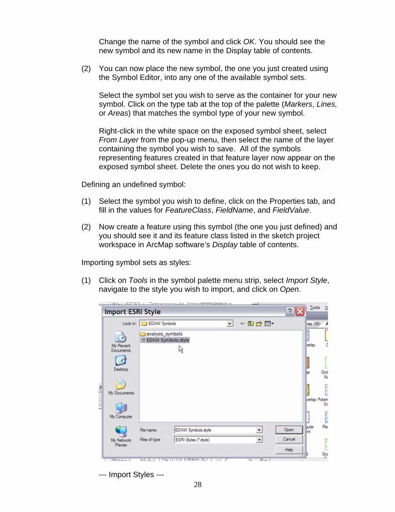
Importing symbol sets as styles: (1) Click on Tools in the symbol palette menu strip, select Import Style,
navigate to the style you wish to import, and click on Open.
--- Import Styles ---
29
Importing symbols from a layer: (1) Select the symbol set you wish to serve as the container palette for
your new symbols. Click on the type tab at the top of the symbol palette (Markers, Lines, or Areas) that matches the symbol type of the symbols you wish to import.
(2) Right click in the white space on the exposed symbol sheet, select
From Layer from the pop-up menu, then select the name of the layer containing the symbols you wish to import. The symbols should now appear on the exposed symbol sheet.
Exercise 3: Working with layers
Ordering layers in the TOC: – This capability is currently not available. (1) The order in which they are listed in the Display table of contents
affects the order in which the layers are displayed in the map. (2) Users can change this order by simply dragging the sketch layers
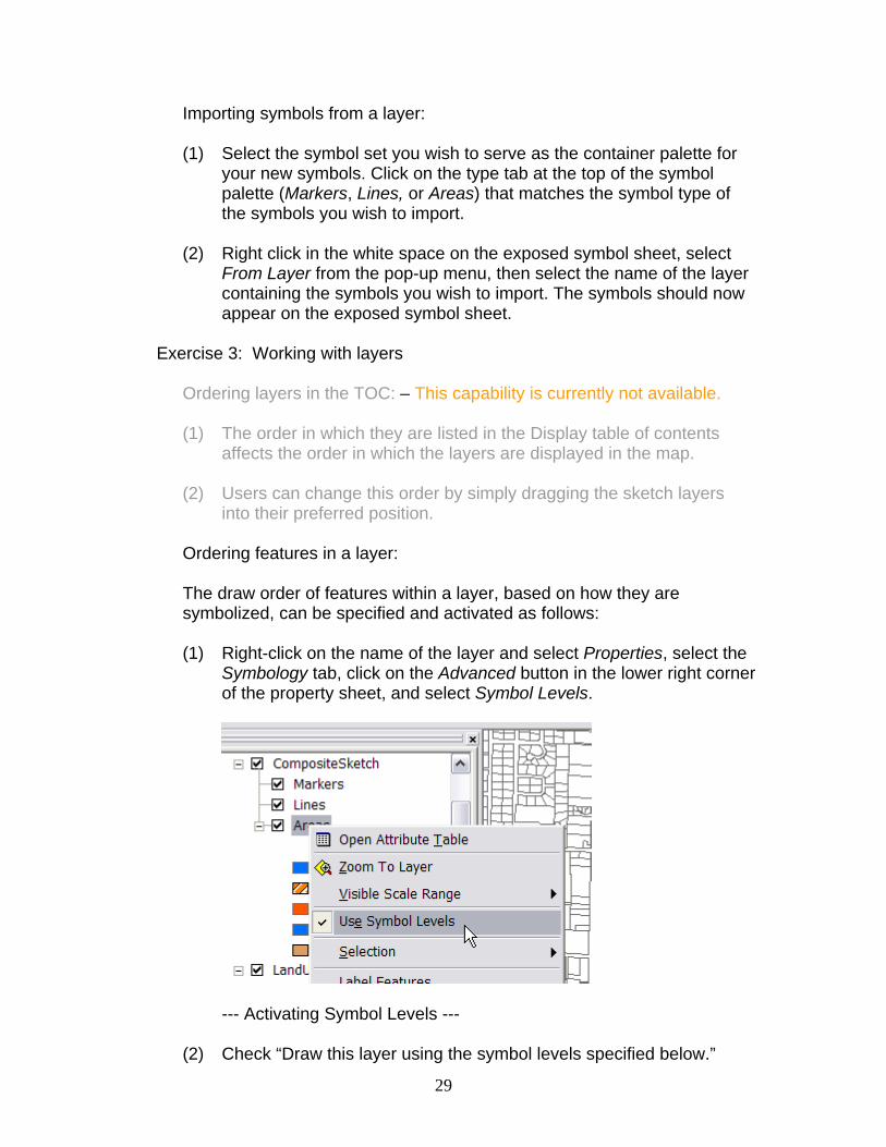
into their preferred position. Ordering features in a layer: The draw order of features within a layer, based on how they are symbolized, can be specified and activated as follows: (1) Right-click on the name of the layer and select Properties, select the
Symbology tab, click on the Advanced button in the lower right corner of the property sheet, and select Symbol Levels.
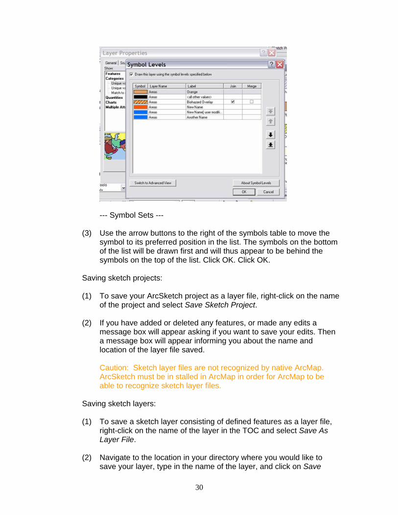
--- Activating Symbol Levels --- (2) Check “Draw this layer using the symbol levels specified below.”
30
--- Symbol Sets --- (3) Use the arrow buttons to the right of the symbols table to move the
symbol to its preferred position in the list. The symbols on the bottom of the list will be drawn first and will thus appear to be behind the symbols on the top of the list. Click OK. Click OK.
Saving sketch projects: (1) To save your ArcSketch project as a layer file, right-click on the name
of the project and select Save Sketch Project. (2) If you have added or deleted any features, or made any edits a
message box will appear asking if you want to save your edits. Then a message box will appear informing you about the name and location of the layer file saved.
Caution: Sketch layer files are not recognized by native ArcMap. ArcSketch must be in stalled in ArcMap in order for ArcMap to be able to recognize sketch layer files.
Saving sketch layers: (1) To save a sketch layer consisting of defined features as a layer file,
right-click on the name of the layer in the TOC and select Save As Layer File.
(2) Navigate to the location in your directory where you would like to
save your layer, type in the name of the layer, and click on Save

31
Caution: If you want to share a default layer with others, it must be saved as part of a sketch project (see page 59).

32
User Environment Activating ArcSketch adds a small toolbar to ArcMap software’s tool strip. This toolbar is used to create or open an ArcSketch project, which in turn creates a separate sketch project in ArcMap software’s Display table of contents. This toolbar is also used to activate the ArcSketch drawing tools, the ArcSketch symbol palette, and to access ArcMap software’s snapping environment.
--- ArcMap with ArcSketch --- The user interface for ArcSketch consists of four exposed components: The ArcSketch toolbar, the ArcSketch table of contents in the Display tab, the ArcSketch drawing tools, and the ArcSketch symbol palette. ArcSketch also sets up a personal geodatabase for each sketch project created by the user. These personal geodatabases, however, are not exposed in the user interface.
ArcSketch Toolbar The ArcSketch toolbar, when opened, is displayed as a floating toolbar. If you wish, you can dock it in the tool strip near the top of the ArcMap window. It is used to create or load a sketch project, display the ArcSketch drawing tools, display the symbol palette, and provide access to the snapping tools. ArcSketch Table of Contents The ArcSketch table of contents, which lists all the sketch layers for a particular sketch session, is listed at the top of the Display tab in ArcMap.

33
ArcSketch Drawing Tools The ArcSketch drawing tools are used for drawing features (markers, lines, and areas) in a sketch layer. They are also used for selecting and editing sketch features. Caution: The ArcSketch Drawing Tools cannot be used for editing layers that are not in an ArcSketch project. ArcSketch Symbol Palette The ArcSketch Symbol Palette serves as the user interface for managing symbols; how they are selected; how they are created, including how they are defined with respect to their parent feature class, type, and value; and how they are organized into sets (styles). Personal Geodatabase ArcSketch creates a separate personal geodatabase (.mdb file) for each sketch project created by the user.

34
Using the ArcSketch Toolbar The ArcSketch toolbar, when activated, is used to create or load a sketch project, display the ArcSketch drawing tools and the symbol palette, and provide access to the snapping tools.
--- ArcSketch Toolbar ---
Creating a New Sketch Project The user must add at least one background layer to ArcMap before creating a new sketch project.
--- Create New Project --- To create a new sketch project, select the New Sketch Project menu item from the Sketch Projects drop-down menu. When the New Sketch Project dialog box appears, enter the name, location, and description of your project, then click Create.
--- Create New Sketch Project Dialog Box ---

35
Opening an Existing Sketch Project To open an existing sketch project, select the Load Sketch Project item from the Sketch Projects drop-down menu.
--- Open Existing Project --- When the Open Existing Sketch Project dialog box appears, navigate to the folder containing the sketch project you want to open, select the project layer file you previously saved, and click Open.
--- Open Existing Sketch Project Dialog Box --- Display/Close Drawing Tools To display the drawing tools, click on the Sketch Tools icon in the ArcSketch toolbar. To close the drawing tools, click on the icon again.

36
--- Display/Close Sketch Tools --- Display/Close Symbol Palette To display the symbol palette, click on the Show Symbol Set icon in the ArcSketch toolbar. To close the symbol palette, click on the icon again or click on the close window button in the upper right corner of the Symbols Palette.
--- Display/Close Symbol Palette ---

37
Managing the Snapping Environment To display the snapping environment dialog box, click on the Snapping Environment icon in the ArcSketch toolbar. To close the Snapping Environment dialog box, click on the close window button in the upper right hand corner of the Snapping Environment dialog box.
--- Activate the Snapping Environment --- For information on how to use the snapping environment, please refer to the ArcMap User Guide.
--- Manage Snapping Environment ---

38
Using the ArcSketch Table of Contents ArcSketch creates a new project workspace (personal geodatabase) whenever the user creates a new sketch project. The contents of that workspace are displayed as sketch layers under a project node in ArcMap software’s Display table of contents. The contents of this node list the various group layers, layers, and symbols associated with the project.
--- ArcSketch Table of Contents --- The sketch layers for a particular sketch project are either referenced under the project node as a CompositeSketch group layer (containing the default feature layers for undefined markers, lines, and areas) or as separate sketch layers uniquely defined by the user.
ArcSketch Project Layers A separate sketch project node is set up in ArcMap software’s Display table of contents each time the user creates or opens a sketch project. While the Display table of contents can contain multiple sketch projects, only one sketch project can be active at a time.

39
Note: The user can only draw into an active project. The user can determine if a layer in the Display table of contents is a sketch project by the presence of an Active or Inactive icon directly below the name of the project. These icons indicate which sketch project is currently active. The user can activate an inactive sketch project, in the active data frame, by right-clicking on the name of the project and selecting Set Active. Each project has its own CompositeSketch group layer containing the default feature layers for markers, lines, and areas. It can also have, but need not have, any number of separate sketch layers uniquely defined by the user. The contents of a sketch project, including group layers, layers, and feature symbology, are automatically updated as the user adds features to the sketch. Sketch Layers vs. Standard ArcMap Layers Sketch layers are custom layers that have either been created by ArcSketch or imported by ArcSketch into the ArcSketch project workspace. ArcSketch cannot operate on standard ArcMap layers. Most standard layers, however, can be imported (copied) into an ArcSketch project as sketch layers, but the standard layers must use unique renderers. Note: Sketch layers are not recognized by native ArcMap. ArcSketch must be installed in ArcMap in order for ArcMap to be able to recognize sketch layers.. Using the Sketch Project Context Menu The user can right-click on the name of the sketch project to access functions that can be applied to the entire project. If the sketch project is active, you will see the following menu items.
--- Sketch Project Context Menu ---

40
Set Active: Sets the sketch project to active, if that project is in the active data frame, and deactivates all other sketch projects. If the sketch project is not in the active data frame, ArcSketch will display the following warning.
Import from File: Imports a single standard layer or defined sketch layer to the active sketch project workspace. Import from Layer: Imports a standard layer in the Display table of contents to the sketch project workspace. Save Project As Layer File: Saves the sketch project as a sketch layer file. Remove: Removes the sketch project from the Display table of contents but does not delete it from your storage device. Rename: Enables you to rename the sketch project. Description: Displays the description of the project.
Using the Layer Context Menu The context menu for sketch layers gives the user the ability to access many of ArcMap software’s standard layer functions.

41
--- Sketch Layer Context Menu --- Some of the standard functions have been disabled; others should be used with caution. Open Attribute Table: Opens the Attribute Table for the layer. Caution: Do not use the Attribute Table for editing feature attributes. Zoom to Layer: Zooms to the extent of the layer. Visible Scale Range: Sets the visible scale range for the layer. Use Symbol Levels: Sets display order based on symbol classification. Selection: Provides standard selection options for the layer. Label Features: Toggles feature labeling on/off. Convert Features to Graphics: Converts feature labels to graphics. Data: Provides the ability to export features to a shape file or feature class.

42
Save As Layer File: Saves the sketch layer as a layer file. Caution: ArcMap will need ArcSketch installed to view saved layer file. Delete: Deletes both the layer and its underlying feature class. Purge Unused Symbols: Removes symbols from the layer’s renderer that are no longer represented on the map.
Properties: Opens the Property Sheet for the layer.
Caution: In general, one should not use the Property Sheet for editing layer properties. Users should definitely avoid using the Fields sheet, the Definition Query sheet, and the Joins & Relates sheet. Caution: The Source Sheet should be used for viewing; however, in the situation where the layer’s data source is broken, you can use Set Data Source to repair the data source link for the layer. Caution: The Symbology sheet should be used for viewing only, however, the Advanced button on the Symbology sheet can be used to control the draw order of features using Symbol Levels. The Display sheet can be used to control transparency.
Importing Layers to the Sketch Project As previously mentioned, ArcSketch cannot be used to edit standard ArcGIS layers. Users can, however, use standard layers by importing (copying) them into the sketch workspace. The user can import either background layers, layers already listed in the Display table of contents, or layers stored as a layer file in a directory. A standard layer must use a unique renderer in order to be imported into a sketch project. To import a layer into a sketch project, right-click on the name of the project and select Import from Layer (if you want to import a layer already listed in the Display table of contents) or Import from File (if you want to import a layer file stored in a directory) and follow the instructions in the dialog boxes. All layers imported into a sketch project are actually copies of the source data. Any changes you make to the imported layers will not affect the source layers.

43
Using the ArcSketch Drawing Tools The ArcSketch drawing tools are used to create and edit features in a sketch layer. As such, they are used for drawing features (markers, lines, and areas) in a sketch layer and for selecting and editing sketch features. They cannot be used for editing layers that are not in the sketch project workspace.
--- ArcSketch Drawing Toolbar --- When activated, the ArcSketch drawing tools temporarily replace ArcMap software’s Editor tools. That is, when the ArcSketch drawing tools are active, the Editor tools in ArcMap are not. Conversely, activating the Editor Tools will deactivate the ArcSketch drawing tools. Selection Tools
--- Sketch Select Tool --- Select Feature: Click on the left mouse button to select a single feature, or depress the left mouse button, then drag the mouse and release the button to select all features within or partially within a rectangle.

44
--- Context Menu for Selected Feature --- If a single feature is selected, the user can right-click on the feature to get a context menu allowing the user to perform a number of functions:
• Activate the symbol editor • Display feature attributes • Move the feature a specific x-y distance • Duplicate the feature • Replicate the feature • Delete the feature
To deselect the selected feature or features, simply move the cursor to an empty space on the map and click the left mouse button.
--- Select by Symbol --- Select by Symbol: Used to click on a specific feature in order to select all features created with the same symbol.
--- Select by Attributes ---
45
Select by Attributes: Used to select features based on their attributes. The user creates a select clause, as they would in ArcMap, to define the selection.
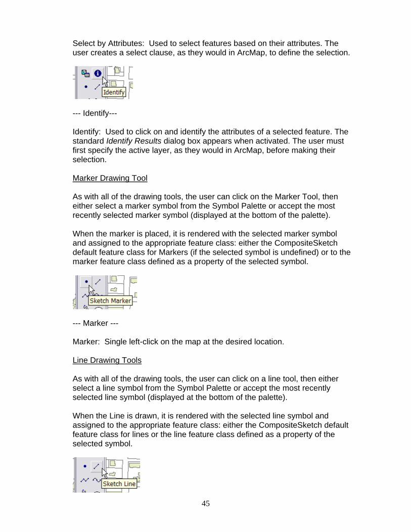
--- Identify--- Identify: Used to click on and identify the attributes of a selected feature. The standard Identify Results dialog box appears when activated. The user must first specify the active layer, as they would in ArcMap, before making their selection.
Marker Drawing Tool As with all of the drawing tools, the user can click on the Marker Tool, then either select a marker symbol from the Symbol Palette or accept the most recently selected marker symbol (displayed at the bottom of the palette). When the marker is placed, it is rendered with the selected marker symbol and assigned to the appropriate feature class: either the CompositeSketch default feature class for Markers (if the selected symbol is undefined) or to the marker feature class defined as a property of the selected symbol.
--- Marker --- Marker: Single left-click on the map at the desired location.
Line Drawing Tools As with all of the drawing tools, the user can click on a line tool, then either select a line symbol from the Symbol Palette or accept the most recently selected line symbol (displayed at the bottom of the palette). When the Line is drawn, it is rendered with the selected line symbol and assigned to the appropriate feature class: either the CompositeSketch default feature class for lines or the line feature class defined as a property of the selected symbol.

46
--- Line --- Sketch Line: Single left-click or double left click at the start of the line, then single left-click or double left-click at the end of the line. Any combination of single- or double-clicking will work.
--- Polyline --- Sketch Polyline: Single left-click at the start of the polyline, single left-click at all intermediate points along the polyline, then double left-click at the end of the polyline.
--- Curved Polyline --- Sketch Curved Polyline: Single left-click at the start of the curved polyline, single left-click at all intermediate points along the curved polyline, then double left click at the end of the curved polyline.
--- Sketch Freehand Polyline Tool --- Sketch Freehand Polyline: You can either: (1) Depress the left mouse button, hold it down as you drag the mouse along the path of the freehand polyline, then release the button at the end of the freehand polyline, or (2) do a left-click at the beginning of the line, move the mouse along the desired path, then do a left-click at the end of the line.

47
Area Drawing Tools
As with all of the drawing tools, the user can click on an area tool, then either select an area symbol from the Symbol Palette or accept the most recently selected area symbol (displayed at the bottom of the palette). When the area is drawn, it is rendered with the selected area symbol and assigned to the appropriate feature class: either the CompositeSketch default feature class for areas or to the area feature class defined as a property of the selected symbol.
--- Circle/Ellipse --- Circle/Ellipse: To draw a circle, move the cursor to the center of the circle, press and hold the left mouse button, drag the mouse to specify its radius, then release the mouse button. To draw an ellipse, move the cursor to the center of the ellipse, press and hold the left mouse button, drag the mouse to create its radius (as you would to draw a circle), press and hold down the Shift key and drag the mouse to form the ellipse, then release the mouse button. If while drawing an ellipse, you wish to change the radius, while holding down the mouse button, let go of the shift key, and depress the control key, then move the mouse. The tool will revert to drawing a perfect circle. Once the shape of the ellipse has been formed, its position can be further adjusted by selecting it, then using the associated feature transformation tools. (For additional information, please refer to the last section in this portion of the user guide titled Feature Transformation Tools.)
--- Square/Rectangle --- Rotated Rectangle: To draw a square or rectangle that is orthogonal to the map window, move the cursor to a corner of the square or rectangle, press and hold the left mouse button, drag the mouse to create the shape of the square or rectangle, then release the mouse button.
48
To draw a square or rectangle that is not orthogonal to the map window, move the cursor to a corner of the square or rectangle (depending on which corner you wish to serve as the point of rotation), press and hold the left mouse button, drag the mouse to create the shape of the square or rectangle (as you would to draw one that is orthogonal to the map window), press and hold down the Shift key and drag the mouse to rotate the shape, then release the mouse button. Once the shape and orientation of the square or rectangle has been formed, its position can be further adjusted by selecting it, then using the associated feature transformation tools. (For additional information please refer to the last section in this portion of the user guide titled Feature Transformation Tools.)
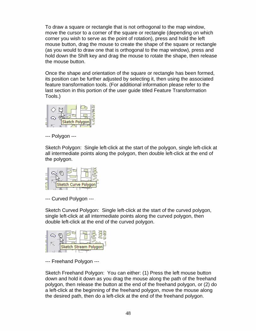
--- Polygon --- Sketch Polygon: Single left-click at the start of the polygon, single left-click at all intermediate points along the polygon, then double left-click at the end of the polygon.
--- Curved Polygon --- Sketch Curved Polygon: Single left-click at the start of the curved polygon, single left-click at all intermediate points along the curved polygon, then double left-click at the end of the curved polygon.
--- Freehand Polygon --- Sketch Freehand Polygon: You can either: (1) Press the left mouse button down and hold it down as you drag the mouse along the path of the freehand polygon, then release the button at the end of the freehand polygon, or (2) do a left-click at the beginning of the freehand polygon, move the mouse along the desired path, then do a left-click at the end of the freehand polygon.
49
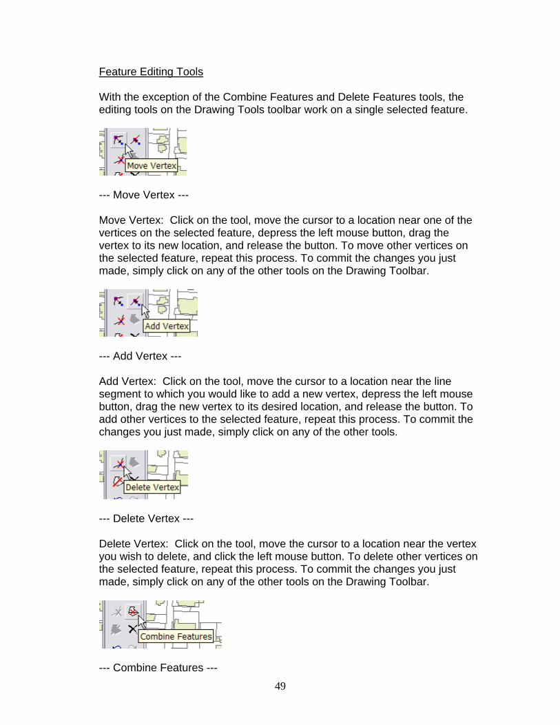
Feature Editing Tools
With the exception of the Combine Features and Delete Features tools, the editing tools on the Drawing Tools toolbar work on a single selected feature.
--- Move Vertex --- Move Vertex: Click on the tool, move the cursor to a location near one of the vertices on the selected feature, depress the left mouse button, drag the vertex to its new location, and release the button. To move other vertices on the selected feature, repeat this process. To commit the changes you just made, simply click on any of the other tools on the Drawing Toolbar.
--- Add Vertex --- Add Vertex: Click on the tool, move the cursor to a location near the line segment to which you would like to add a new vertex, depress the left mouse button, drag the new vertex to its desired location, and release the button. To add other vertices to the selected feature, repeat this process. To commit the changes you just made, simply click on any of the other tools.
--- Delete Vertex --- Delete Vertex: Click on the tool, move the cursor to a location near the vertex you wish to delete, and click the left mouse button. To delete other vertices on the selected feature, repeat this process. To commit the changes you just made, simply click on any of the other tools on the Drawing Toolbar.
--- Combine Features ---
50
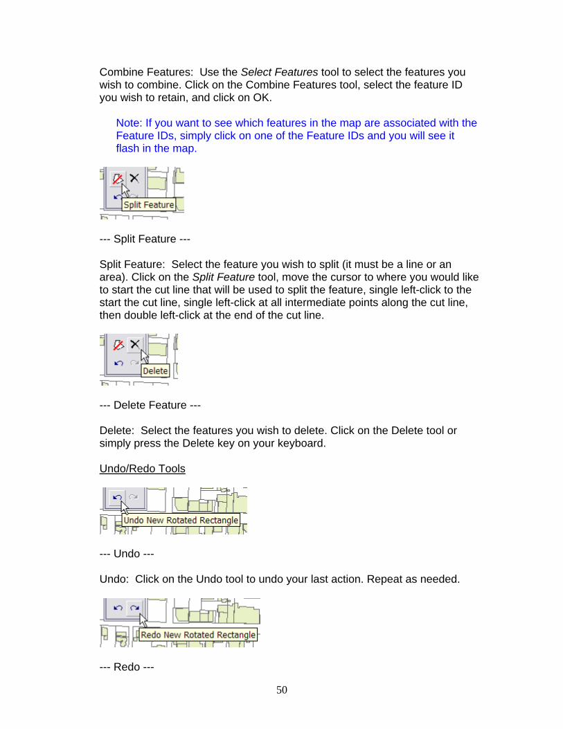
Combine Features: Use the Select Features tool to select the features you wish to combine. Click on the Combine Features tool, select the feature ID you wish to retain, and click on OK.
Note: If you want to see which features in the map are associated with the Feature IDs, simply click on one of the Feature IDs and you will see it flash in the map.
--- Split Feature --- Split Feature: Select the feature you wish to split (it must be a line or an area). Click on the Split Feature tool, move the cursor to where you would like to start the cut line that will be used to split the feature, single left-click to the start the cut line, single left-click at all intermediate points along the cut line, then double left-click at the end of the cut line.
--- Delete Feature --- Delete: Select the features you wish to delete. Click on the Delete tool or simply press the Delete key on your keyboard. Undo/Redo Tools
--- Undo --- Undo: Click on the Undo tool to undo your last action. Repeat as needed.
--- Redo ---
51
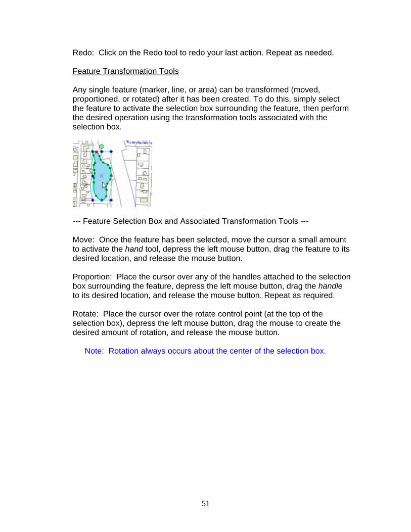
Redo: Click on the Redo tool to redo your last action. Repeat as needed. Feature Transformation Tools Any single feature (marker, line, or area) can be transformed (moved, proportioned, or rotated) after it has been created. To do this, simply select the feature to activate the selection box surrounding the feature, then perform the desired operation using the transformation tools associated with the selection box.
--- Feature Selection Box and Associated Transformation Tools --- Move: Once the feature has been selected, move the cursor a small amount to activate the hand tool, depress the left mouse button, drag the feature to its desired location, and release the mouse button. Proportion: Place the cursor over any of the handles attached to the selection box surrounding the feature, depress the left mouse button, drag the handle to its desired location, and release the mouse button. Repeat as required. Rotate: Place the cursor over the rotate control point (at the top of the selection box), depress the left mouse button, drag the mouse to create the desired amount of rotation, and release the mouse button.
Note: Rotation always occurs about the center of the selection box.
52
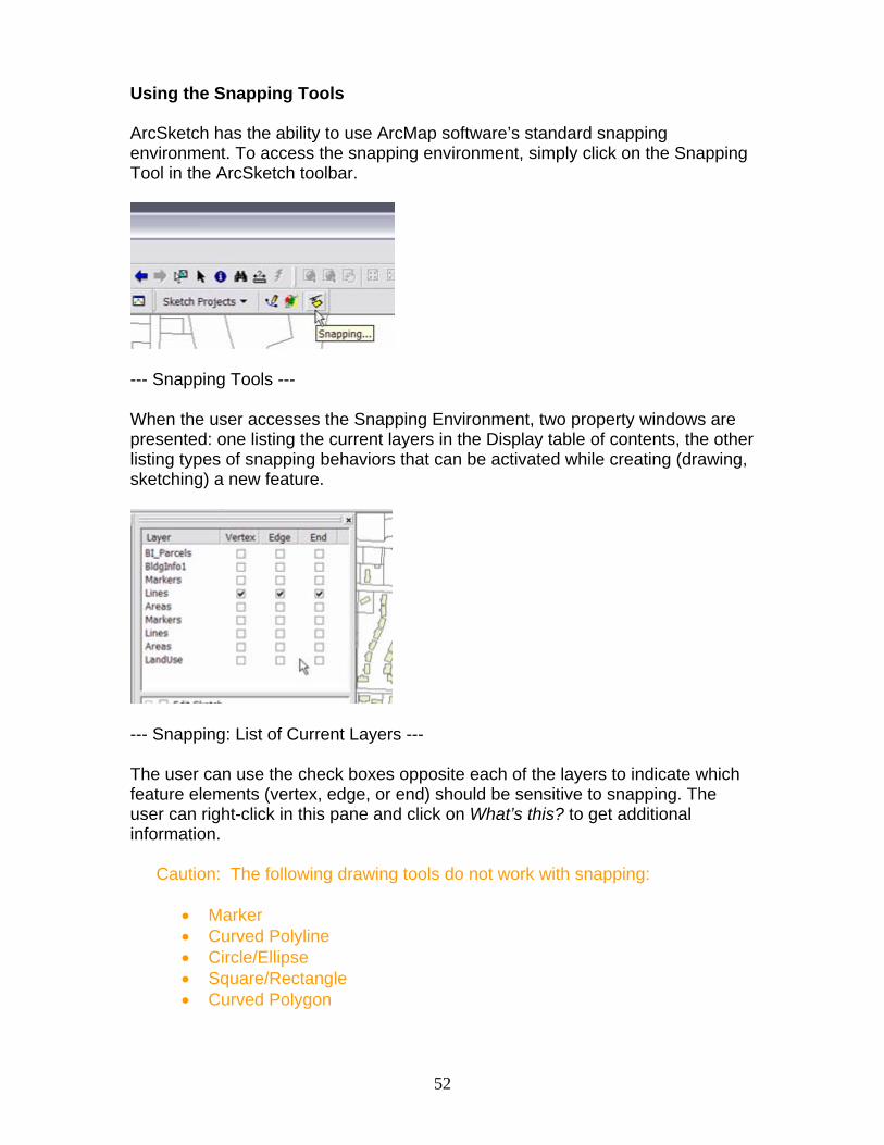
Using the Snapping Tools ArcSketch has the ability to use ArcMap software’s standard snapping environment. To access the snapping environment, simply click on the Snapping Tool in the ArcSketch toolbar.
--- Snapping Tools --- When the user accesses the Snapping Environment, two property windows are presented: one listing the current layers in the Display table of contents, the other listing types of snapping behaviors that can be activated while creating (drawing, sketching) a new feature.
--- Snapping: List of Current Layers --- The user can use the check boxes opposite each of the layers to indicate which feature elements (vertex, edge, or end) should be sensitive to snapping. The user can right-click in this pane and click on What’s this? to get additional information.
Caution: The following drawing tools do not work with snapping:
• Marker • Curved Polyline • Circle/Ellipse • Square/Rectangle • Curved Polygon

53
--- Snapping: List of Behaviors --- The user can check the boxes in this list to activate the indicated behaviors. The user can right-click in this pane and click on What’s this? to get additional information.
54
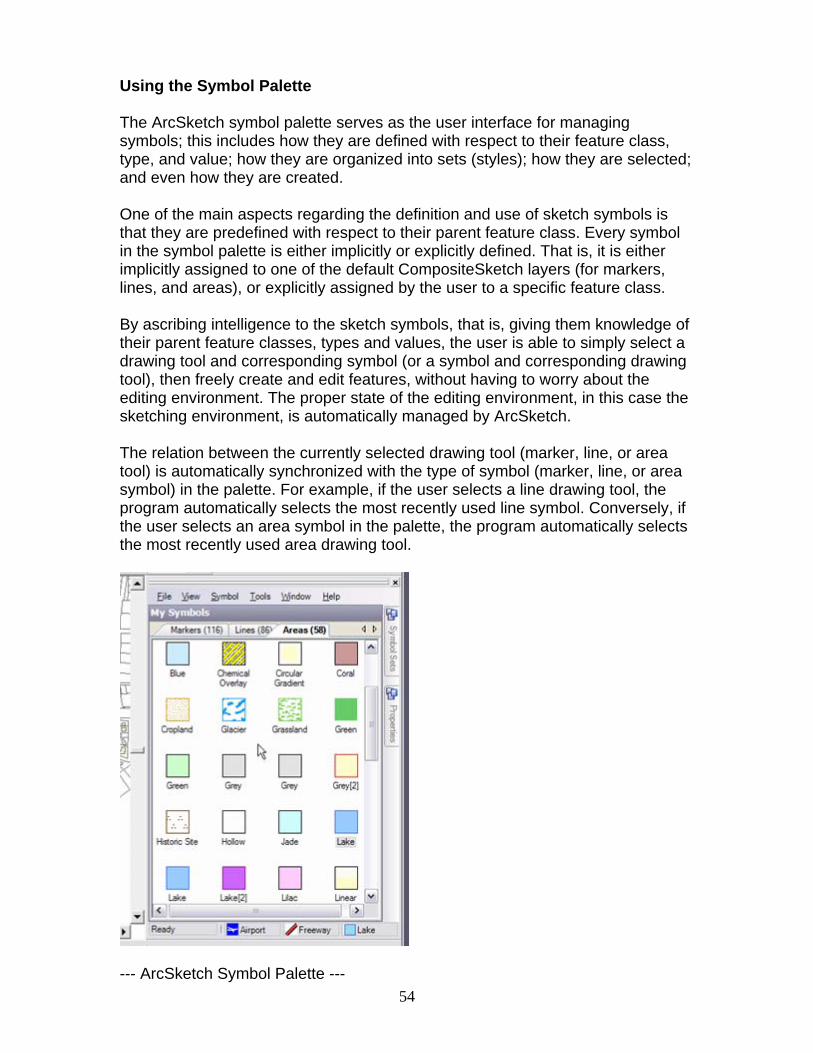
Using the Symbol Palette The ArcSketch symbol palette serves as the user interface for managing symbols; this includes how they are defined with respect to their feature class, type, and value; how they are organized into sets (styles); how they are selected; and even how they are created. One of the main aspects regarding the definition and use of sketch symbols is that they are predefined with respect to their parent feature class. Every symbol in the symbol palette is either implicitly or explicitly defined. That is, it is either implicitly assigned to one of the default CompositeSketch layers (for markers, lines, and areas), or explicitly assigned by the user to a specific feature class. By ascribing intelligence to the sketch symbols, that is, giving them knowledge of their parent feature classes, types and values, the user is able to simply select a drawing tool and corresponding symbol (or a symbol and corresponding drawing tool), then freely create and edit features, without having to worry about the editing environment. The proper state of the editing environment, in this case the sketching environment, is automatically managed by ArcSketch. The relation between the currently selected drawing tool (marker, line, or area tool) is automatically synchronized with the type of symbol (marker, line, or area symbol) in the palette. For example, if the user selects a line drawing tool, the program automatically selects the most recently used line symbol. Conversely, if the user selects an area symbol in the palette, the program automatically selects the most recently used area drawing tool.
--- ArcSketch Symbol Palette ---
55
The Symbol Palette contains a menu bar, a palette of symbols, tabs for accessing symbol sets and symbol properties, and a status bar showing the most recently selected symbols.
Menu Bar The menu bar contains the following drop-down menus:
File: Print: Prints the current symbol sheet Close: Closes the Symbol Palette View: Small icons: Displays small icons for each symbol Large icons: Displays large icons for each symbol Details: Displays small icons and properties for each symbol Show Markers Tab: Displays the Markers page Show Lines Tab: Displays the Lines page Show Areas Tab: Displays the Areas page Symbol: New: Creates new symbol Cut: Cuts a symbol so it can be pasted elsewhere Copy: Copies a symbol so it can be pasted elsewhere Paste: Pastes a symbol into the palette Delete: Deletes a symbol from the palette Select All: Selects all symbols on the palette Edit Graphic: Edits the graphics for a selected symbol From Layer: Copies symbols from selected layer to palette Update Map: Updates the symbols on the sketch layers Tools: New Style: Creates a new style Import Style: Imports an existing style Window: Split Horizontal: Shows the symbol sheets split horizontally Split Vertical: Shows the symbol sheets split vertically Remove Split: Removes the split (this is the default) Help: ArcSketch Help: Points the user to the ArcSketch web page About ArcSketch: Shows the current version of ArcSketch
Styles are automatically saved to ArcSketch’s default symbol directory, which is typically \My Documents\ArcSketch\Styles. Symbols (for markers, lines, and areas) The symbols for each symbol set are classified with respect to their geometry type (mark, line, or area) and arranged on tabbed pages, with a separate page for each geometry type. The number of symbols on a given page is shown to the right of the name on the tab for that page.

56
--- Symbol Page Tabs and Scroll Arrows --- The default order of the tabs is Markers/Lines/Areas. The order of the tabs can be changed by dragging them to their preferred position. If the symbol palette window is too narrow to display all of the tabs, the user can scroll the tabs using the left and right arrows to the right of the tabs. Symbol Sets ArcSketch comes with a wide range of symbol sets. These sets can be accessed by clicking on the vertical Symbol Sets tab on the right edge of the palette. The user can select any of the symbol sets displayed on the tabbed page.
--- Symbol Sets Page --- The size of the Symbol Sets page can be changed by placing the cursor over the left margin of the page and dragging it to the left (to expand) or right (to contract).
Note: The My Symbols page can be used as a scratch space for creating and editing the user’s personal symbols.
The Symbol Sets page can be closed by double-clicking on the horizontal pin in the upper right corner of the page or by clicking anywhere outside of the page.
57
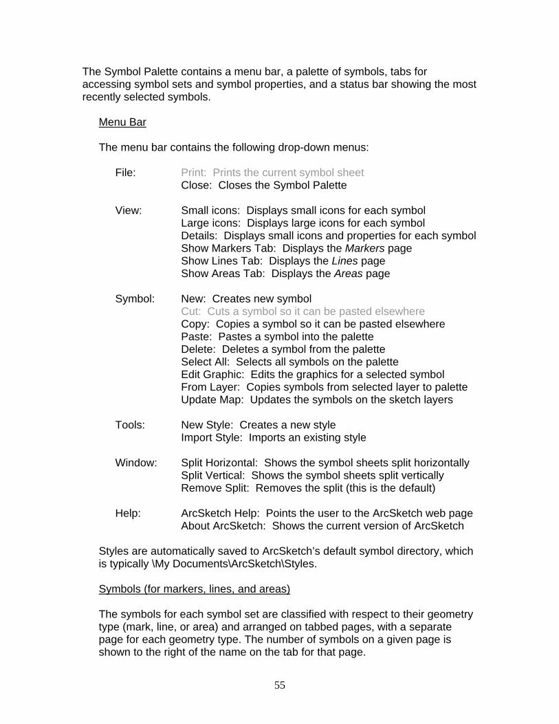
The Symbol Sets page can be moved to a new location by clicking once on the horizontal pin (converting it to a vertical pin), then placing the cursor over the page’s title bar and dragging it to the new location. The user can add or remove symbols sets (styles) by left-clicking on the right arrow in the lower right hand corner of the page and selecting Add or Remove Styles. Symbol Properties The user can display and edit the properties of any selected symbol by left-clicking on the vertical Properties tab on the right edge of the Symbol Palette.
--- Symbol Properties Page --- The size of the Properties page can be changed by placing the cursor over the left margin of the page and dragging it to the left (to expand) or right (to contract). The Properties page can be closed by double-clicking on the horizontal pin in the upper right corner of the page or by clicking anywhere outside of the page. The Properties page can be moved to a new location by clicking once on the horizontal pin (converting it to a vertical pin), then placing the cursor over the page’s title bar and dragging it to the new location. The properties of the selected symbol can be edited by simply editing the content of a selected field or by typing in a new value.

58
The properties include: Name: The name of the symbol will be displayed in the TOC as part of the legend for the features drawn with this symbol. Category: If this field is blank, the features are rendered with this symbol and drawn into the appropriate default sketch layer (Markers, Lines, or Areas) of the active sketch project. Description: Description about this symbol. Feature Class: If the symbol is undefined, this field is blank. If the symbol is defined, it contains the name of the feature class containing this symbol. Field Name: If the symbol is undefined, this field is blank. If the symbol is defined it contains the name of the attribute field containing the value assigned to the symbol. Field Value: If the symbol is undefined, this field is blank. If the symbol is defined, it contains the value assigned to the symbol. Caution: “Markers,” “Lines,” and “Areas” are feature class names reserved for the default sketch layers; as such, you cannot use them in your Feature Class definitions. Current Symbols The most recently selected marker, line, and area symbols are displayed at the bottom of the Symbol Palette. Symbol Editing To create a new symbol, right-click on the symbol page away from a symbol and select New. A new symbol will appear on the page.
--- Portion of the Symbol Page Showing the New Symbol --- To edit the graphic representation of a symbol in the symbol palette, either right-click on the symbol and select Edit Graphic from the menu or simply double-click on the symbol.
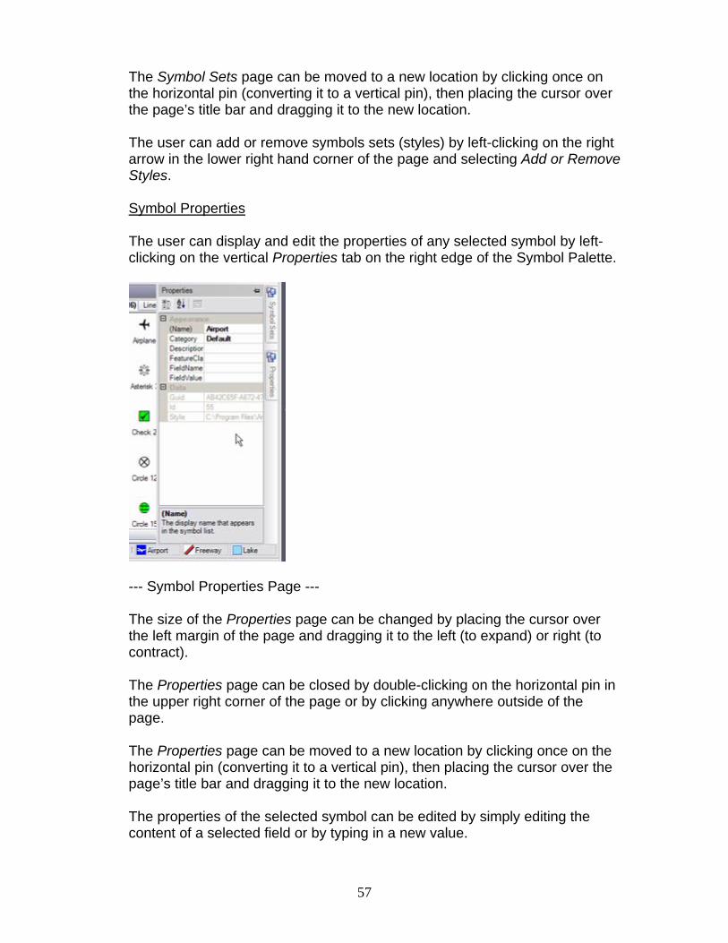
59
--- Symbol Editor Dialog Box --- To edit the graphic representation of a symbol in the drawing, first select the feature, then right-click on the feature and select Edit Symbology from the menu. Finding Symbols All but the simplest form of sketching can lead to the use, and even creation, of many different symbols. As such, it is relatively easy to lose track of the parent symbol set for each symbol. Users can right-click on a selected feature, then choose the Find Symbol in Palette menu item. The system will then jump to the parent symbol sheet for that symbol and highlight the selected symbol on the symbol sheet.

60
Saving and Sharing Your Work Users can save their work and share it with others. They can save and share the entire map document, the sketch project, any layer in the project, or any of the symbol sets (styles) used during the creation of the project.
Saving a Sketch Project as Part of a Map Document Users can save their sketch project as part of a map document by clicking on the File/Save or File/Save As command in ArcMap software’s main menu. Before you save or export your work, you should save your edits as follows: click the Sketch Tools button on the ArcSketch toolbar, click Save Edits in the Editor drop-down menu, and click once again on the Sketch Tools button on the ArcSketch toolbar. Saving a Sketch Project as a Separate Layer File Users can save their sketch project as a separate layer file by right-clicking on the name of the project and selecting Save Sketch Project. This will save the sketch project to a layer file with the same name as the sketch project and in the same location as the sketch project’s workspace. A message will appear asking you if you would like to save your recent edits along with the layer file. A second message will appear informing you as to the name and location of the saved layer file. Caution: The sketch projects needs to be active in order to be saved as a layer file. Saving a Single Sketch Layer Users can save a single sketch layer as a layer file by right-clicking on the name of the layer and selecting Save As Layer File. Only defined sketch layers can be imported into sketch projects. So there’s no point to saving a default sketch layer (Markers, Lines, or Areas). Saving a Symbol Set Symbols and symbol sets are automatically saved to ArcSketch’s default symbol directory, which is typically \My Documents\ArcSketch\Styles. Sharing One Sketch Layer with Others Currently, you need to share the entire project to share any default layers (Markers, Lines, or Areas) in the project. Sender: (1) Follow the steps for sharing the entire project.

61
Recipient: (1) Follow the steps for loading the shared project. (2) After the shared project is in the TOC and the broken data links (if any)
are repaired, follow the instructions for Importing Sketch layers to import the layers of interest from the shared project into your own project.
Sharing Your Sketch Project with Others Once they are saved, sketch projects can be shared with others, either as part of an ArcMap document (.mxd) or as a separate project layer file (.lyr).
Sharing your sketch project as part of the .mxd file: Sender: (1) Save your ArcMap session with your sketch project. (2) Send the recipient your .mxd file containing the sketch project(s) to
share and the sketch project workspace .mdb file(s). Recipient: (1) Place Sender’s files in desired location. (2) Double-click on the .mxd file to start ArcMap. The ArcSketch project(s)
will appear in the TOC. The sketch layers may appear with broken data source links if any project workspace resides in a directory that is different from that on the Sender’s computer.
(3) If any ArcSketch project has broken data source links, right-click on any
layer of this project and select the menu item Data Set Data Source. Navigate to where you placed the project workspace, find the corresponding feature class, and select it. The data source link for all the layers in this sketch project will be repaired.
Caution: If you have multiple sketch projects, with broken links in each
project, this will set all the broken links for all projects to the source of the first project. You may have to manually fix broken links in additional projects.
(4) Set the project to active (right-click on the project Set Active) if you
want to work on this project. Sharing your sketch project through a project layer file:
62
Sender: (1) In ArcMap, set the sketch project to active if it is not already. (2) Right-click on the sketch project to be shared and select the Save to
Layer File menu item. The sketch project will be saved in a layer file located in the same directory as the project workspace, with the same name as the project workspace and ".lyr" extension in the file name.
(3) Send the recipient this layer file together with the project workspace
*.mdb file. Recipient: (1) Place the *.lyr file and *.mdb file in desired location. It is recommended
that the files stay together in the same directory. (2) In an ArcMap session, load the project by clicking Sketch Projects drop-
down menu Load Sketch Projects; navigate to and select the project layer file.
(3) The ArcSketch project in the layer file will appear in the TOC. The
sketch layers may appear with broken data source links if the project workspace resides in a directory that is different from that on the Sender’s computer.
(4) If the ArcSketch project has broken data source links, right-click on any
layer of this project and select the menu item Data Set Data Source. Navigate to where you placed the project workspace, find the corresponding feature class, and select it. The data source link for all the layers in this sketch project will be repaired.
Caution: If you have multiple sketch projects, with broken links in each
project, this will set all the broken links for all projects to the source of the first project. You may have to manually fix broken links in additional projects.
(5) Set the project to active (right-click on the project Set Active) if you
want to work on this project. Sharing Symbol Sets with Others Symbol sets (style files) can be shared with others using the standard copy/paste commands available in Windows Explorer.

63
Working Directly with an ArcSketch Personal Geodatabase ArcSketch sets up a personal geodatabase every time the user creates a new sketch project. This personal geodatabase, as with all personal geodatabases, can be utilized by other components of ArcGIS, such as ArcCatalog and ArcGlobe. This gives the user the ability to perform a variety of functions and operations on the data.
Caution: Users should not attempt to manipulate or edit a personal geodatabase created with ArcSketch.
Adding Labels to ArcSketch Layers Labels can be added to a sketch project using ArcMap software’s standard tools for creating labels. These tools are part of ArcMap software’s standard graphics tools, which are found at the bottom of the ArcMap window.
--- ArcMap software’s Graphics Toolbar --- The labels, as well as the other forms of annotation (graphic shapes, etc.), are added to a standard graphics layer in ArcMap.
Caution: The graphics layer is not part of the sketch project but rather part of the map document. As such, it cannot be saved as part of a sketch layer file. It can only be saved as part of the map document.

64
Using ModelBuilder with ArcSketch The contents of an ArcSketch project can be used as input to a ModelBuilder model. The user must construct the model and specify the name of the specific feature class in the sketch project as one of the inputs to the model.
Caution: The user must also select the relevant features in the specified feature class before running the model.
--- ArcSketch and ModelBuilder --- The user can draw (sketch) features into the specified feature class, select those features, and run the model. The user can draw and select a new set of features, then run the model again. This sequence of drawing and modeling can be performed as often as necessary. Using this technique, the user can use the results of the model as a way to obtain instant feedback regarding the impacts, consequences, or implications suggested by the drawing. One can think of this as a form of interactive design (sketching) and analysis (running the model).
65
Creating Summary Reports with ArcSketch The standard report generator in Crystal Reports (that comes with ArcGIS) can be linked to a ModelBuilder model. Using this link, together with the user’s ability to run ModelBuilder models while sketching, gives the user the ability to generate almost any type of report (summary reports, impact assessments, etc.) while sketching. Technical Support ArcSketch is not a fully developed product but rather a working prototype, designed to explore some new and exciting possibilities with respect to sketching and user-friendly editing. Consequently, it is not supported by ESRI’s Technical Support Group. A Web site and user forum, however, have been set up to assist users who wish to give ArcSketch a try, or use it in their work, and to provide a venue for user feedback.
The ArcSketch Web Site Information regarding ArcSketch and symbol sets can be accessed at: http://www.esri.com/arcsketch/ FAQs Frequently asked questions (FAQs) about ArcSketch can be accessed at: http://www.esri.com/arcsketch/ Discussion Forum The ArcSketch discussion forum can be accessed at: http://www.esri.com/arcsketch/

66
Copyright © 2006 ESRI. All Rights Reserved. Created by the GeoDesign Group, ESRI Redlands Portions of this work are the intellectual property of Divelements Limited and are used herein under license. Copyright © 2003-2006 Divelements Limited. All rights reserved. The information contained in this document is the exclusive property of Environmental Systems Research Institute, Inc. and its licensor(s). This work is protected under United States copyright law and other international copyright treaties and conventions. Unauthorized reproduction or distribution of this program, or any portion of it, may result in severe civil and criminal penalties, and will be prosecuted to the maximum extent possible under the law. No part of this work may be reproduced or transmitted in any form or by any means, electronic or mechanical, including photocopying and recording, or by any information storage or retrieval system, except as expressly permitted in writing by Environmental Systems Research Institute, Inc. All requests should be sent to Attention: Contracts Manager, Environmental Systems Research Institute, Inc., 380 New York Street, Redlands, CA 92373 USA.
The information contained in this document is subject to change without notice. ArcSketch is a trademark of ESRI in the United States, the European Community, or certain other jurisdictions. Other companies and products mentioned herein are trademarks or registered trademarks of their respective trademark owners.