ardig p kins state of south dakota p 0231(15)79 &...
TRANSCRIPT

DAKOTA
SOUTH
STATE OFPROJECT
SHEETSHEETS
TOTAL
2
CNW R.R.
DINOSAUR PARK
SENIOR
PARK
RAPID CITY
WATER
445231 1 90
44
CEMENT PLANT RD.
AVE.
JO
YA
VE.
CLOVER ST.CHICAGO ST. 3
9T
H S
T.
OMAHA ST.
LN.
W. 38
TH
PL
AT
TS
T.
MAIN
ST.
FE
DE
RA
LA
VE.
KIN
NE
YA
VE.
32
ND
ST. ST.
W.
LOUIS
VA
LE
ST.
WEST OMAHA ST.
WEST RAPID ST.
ST.
ON
GE
ST.
KR
EB
S
ST.
SH
EFF
ER
ST.
ST.
CR
OS
S
ST.
CA
NA
L
ST.
OS
HK
OS
H
WES
T
BL
VD.
ST. EL
EV
EN
TH S
T.
NO
RD
BY
HALLST.
BROOKSIDE
DR.
REDER ST.
38
TH
ST.
37
TH
ST.
36
TH
ST.
SO
O
HALL
ST.
WEST SOUTH ST.
ST.MAIN
ST.
TR
EE
PL
UM
LN.
PIE
DM
ON
T
ST.
HA
RT
ER
DR.
DA
KO
TA
DR.
VIE
W
RD.
LA
NE
KIR
KE
BY
GIL
L
AV
E.
KANSAS CITY ST.SHAVER ST.VALENTINE ST.
DR.
JA
MES
WA
RRE
N
WEST RAPID ST.
12T
H
RAPID ST.
PIN
E
HEIGHTS DR.
ST.
WES
T
W.
ST.
PL
OOF DR.
LA
KE
RD.
MO
UN
TAIN
FULTON ST.CLARK ST.
KANSASCITY
QUNICY
COLUM BUS
SOUTH
FULTON ST.
ST.
ST.
9T
H
8T
H
7T
H
6T
H
33 34
4 3
34 35
3
LINCOLN
SCHOOL
CENTRAL
HIGHSCHOOL
ELEM.
SIOUX
REGIONALHOSPITALWEST
TREATMENTPLANT
NATIONALGUARD
CAMP
SOUTH
CANYON
SCHOOL
STATE CEMENT PLANT
SOUTH DAKOTA
DE
AD
WO
OD
ST
UR
GIS
RD.
W.
OMAHA ST.
Sta. 64+14.63 AhSta. 68+21.57 Bk =Equation
INDEX OF SHEETS
STORM WATER PERMIT
None Required
PROJECT
GROSS LENGTH
LENGTH OF EXCEPTIONS
NET LENGTH
STATE OF SOUTH DAKOTA
DEPARTMENT OF TRANSPORTATION
PLANS FOR PROPOSED
MILES
MILES
MILES
FEET
FEET
FEET
03/16/2015Plotting Date:
trrc
11610
1:2
00
Plotted Fro
m -
Plot Scale -
File -
...\prj\P
enn05a5 & 0
5a6\Title.d
gn
BEADLE
KINGSBURY BROOKINGS
HAMLIN
MINER LAKE MOODY
MINNEHAHAMcCOOK
SANBORN
HAND
JERAULD
AURORA
DAVISON HANSON
UNION
LINCOLN
CLAY
YANKTON
TURNER
BON HOMME
HUTCHINSONDOUGLASCHARLES MIX
GREGORY
BRULE
BUFFALO
TRIPP
LYMAN
HUGHES
HYDESULLY
CODINGTONCLARK
GRANT
ROBERTSMARSHALL
DAY
SPINK
BROWNMcPHERSON
EDMUNDS
FAULKPOTTER
WALWORTH
CAMPBELL
STANLEY
JONES
MELLETTE
JACKSON
HAAKON
DEWEYZIEBACH
MEADE
BUTTE
LAWRENCE
PENNINGTON
CUSTER
FALL RIVER
SHANNON
BENNETT TODD
DEUEL
CORSONPERKINS
HARDING
PCN 05A5 & 05A6
NH 0044(196)44 PROJECT P 0231(15)79 &
SD HIGHWAYS 231 & 44
PENNINGTON COUNTY
ADT (2013)
ADT (2033)
DHV
D
T DHV
V
T ADT
25834
45003
5580.4
50 %
1.4 %
3.1 %
40 MPH
DESIGN DESIGNATIONNH 0044(195)44
ADT (2013)
ADT (2033)
DHV
D
T DHV
V
T ADT
6326
11019
1873.2
51 %
3.1 %
6.8 %
35, 50 & 40 MPH
DESIGN DESIGNATIONP 0231(15)79 (South)
ADT (2013)
ADT (2033)
DHV
D
T DHV
V
T ADT
6326
11019
1873.2
51 %
3.1 %
6.8 %
35, 50 & 40 MPH
DESIGN DESIGNATION P 0231(15)79 (North)
CONCRETE PAVEMENT REPAIR
SD 231 SD 44
52’ Roadway182’-3 3/4" Cont. Concrete BridgeStr. No. 52-399-299Sta. 67+55.84 to Sta. 69+38.16EXCEPTION
MRM 44.02
NH 0044(196)44
BEGIN PROJECT
MRM 79.88
Sta 72+57
P 0231(15)79
END PROJECT
Standard Plates22-26
Reseal Tranverse Joint Hot Pour Detail21
PCCP Type A Spall Repair Detail20
Pavement Marking Sheets18-19
Plan Sheet17
Control Data Sheet16
Horizontal Alignment Sheet15
Typical Sections14
Estimate With General Notes & Tables2-13
General Layout W/Index1
GROSS LENGTH
LENGTH OF EXCEPTIONS
NET LENGTH
7,578.94 1.4354 MILES
MILES
MILES
FEET
FEET
FEET
0.1053556.15
1.33017,022.79
0 0
3,305 0.6259
3,305 0.6259
40’ Roadway
373’-10" Prestr. Conc. Girder Bridge
Sta 44+55.03 to 48+28.87
NB Str. No. 52-394-297
40’ Roadway
373’-10" Prestr. Conc. Girder Bridge
Sta 44+80.21 to 48+54.05
SB Str. No. 52-394-298
EXCEPTION
MRM 81.24 +0.06
Sta. 5+29
P 0231(15)79
BEGIN PROJECT
MRM 44.64 + 0.032
Sta. 105+62
NH 0044(196)44
END PROJECT
P 0231(15)79 & NH 0044(196)44 1 26
2
PROJECT STATE OF SOUTH
DAKOTA
SHEET
TOTAL SHEETS
Revised 3-23-15 klh
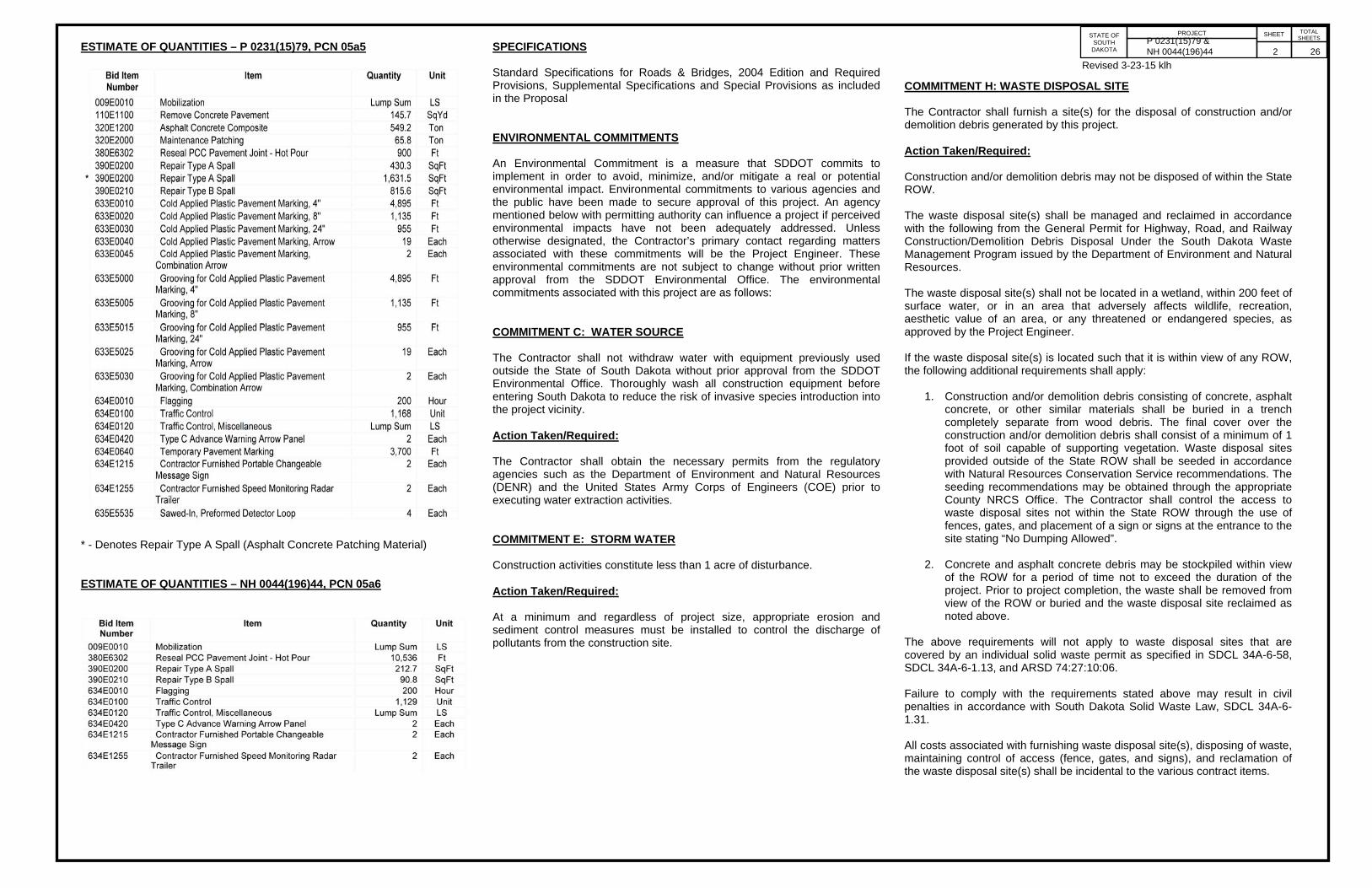
ESTIMATE OF QUANTITIES – P 0231(15)79, PCN 05a5
* - Denotes Repair Type A Spall (Asphalt Concrete Patching Material) ESTIMATE OF QUANTITIES – NH 0044(196)44, PCN 05a6
SPECIFICATIONS Standard Specifications for Roads & Bridges, 2004 Edition and Required Provisions, Supplemental Specifications and Special Provisions as included in the Proposal ENVIRONMENTAL COMMITMENTS An Environmental Commitment is a measure that SDDOT commits to implement in order to avoid, minimize, and/or mitigate a real or potential environmental impact. Environmental commitments to various agencies and the public have been made to secure approval of this project. An agency mentioned below with permitting authority can influence a project if perceived environmental impacts have not been adequately addressed. Unless otherwise designated, the Contractor’s primary contact regarding matters associated with these commitments will be the Project Engineer. These environmental commitments are not subject to change without prior written approval from the SDDOT Environmental Office. The environmental commitments associated with this project are as follows: COMMITMENT C: WATER SOURCE The Contractor shall not withdraw water with equipment previously used outside the State of South Dakota without prior approval from the SDDOT Environmental Office. Thoroughly wash all construction equipment before entering South Dakota to reduce the risk of invasive species introduction into the project vicinity. Action Taken/Required: The Contractor shall obtain the necessary permits from the regulatory agencies such as the Department of Environment and Natural Resources (DENR) and the United States Army Corps of Engineers (COE) prior to executing water extraction activities. COMMITMENT E: STORM WATER Construction activities constitute less than 1 acre of disturbance. Action Taken/Required: At a minimum and regardless of project size, appropriate erosion and sediment control measures must be installed to control the discharge of pollutants from the construction site.
COMMITMENT H: WASTE DISPOSAL SITE The Contractor shall furnish a site(s) for the disposal of construction and/or demolition debris generated by this project. Action Taken/Required: Construction and/or demolition debris may not be disposed of within the State ROW. The waste disposal site(s) shall be managed and reclaimed in accordance with the following from the General Permit for Highway, Road, and Railway Construction/Demolition Debris Disposal Under the South Dakota Waste Management Program issued by the Department of Environment and Natural Resources. The waste disposal site(s) shall not be located in a wetland, within 200 feet of surface water, or in an area that adversely affects wildlife, recreation, aesthetic value of an area, or any threatened or endangered species, as approved by the Project Engineer. If the waste disposal site(s) is located such that it is within view of any ROW, the following additional requirements shall apply:
1. Construction and/or demolition debris consisting of concrete, asphalt concrete, or other similar materials shall be buried in a trench completely separate from wood debris. The final cover over the construction and/or demolition debris shall consist of a minimum of 1 foot of soil capable of supporting vegetation. Waste disposal sites provided outside of the State ROW shall be seeded in accordance with Natural Resources Conservation Service recommendations. The seeding recommendations may be obtained through the appropriate County NRCS Office. The Contractor shall control the access to waste disposal sites not within the State ROW through the use of fences, gates, and placement of a sign or signs at the entrance to the site stating “No Dumping Allowed”.
2. Concrete and asphalt concrete debris may be stockpiled within view
of the ROW for a period of time not to exceed the duration of the project. Prior to project completion, the waste shall be removed from view of the ROW or buried and the waste disposal site reclaimed as noted above.
The above requirements will not apply to waste disposal sites that are covered by an individual solid waste permit as specified in SDCL 34A-6-58, SDCL 34A-6-1.13, and ARSD 74:27:10:06. Failure to comply with the requirements stated above may result in civil penalties in accordance with South Dakota Solid Waste Law, SDCL 34A-6-1.31. All costs associated with furnishing waste disposal site(s), disposing of waste, maintaining control of access (fence, gates, and signs), and reclamation of the waste disposal site(s) shall be incidental to the various contract items.
P 0231(15)79 & NH 0044(196)44 2 26

PROJECT STATE OF SOUTH
DAKOTA
SHEET
TOTAL SHEETS
COMMITMENT I: HISTORICAL PRESERVATION OFFICE CLEARANCES The SDDOT has obtained concurrence with the State Historical Preservation Office (SHPO or THPO) for all work included within the project limits and all designated option borrow sites provided within the plans. Action Taken/Required: All earth disturbing activities not designated within the plans require review of cultural resources impacts. This work includes, but is not limited to: staging areas, borrow sites, waste disposal sites, and all material processing sites. The Contractor shall arrange and pay for a cultural resource survey and/or records search. The Contractor has the option to contact the state Archaeological Research Center (ARC) at 605-394-1936 or another qualified archaeologist, to obtain either a records search or a cultural resources survey. A record search might be sufficient for review; however, a cultural resources survey may need to be conducted by a qualified archaeologist. The Contractor shall provide ARC with the following: a topographical map or aerial view on which the site is clearly outlined, site dimensions, project number, and PCN. If applicable, provide evidence that the site has been previously disturbed by farming, mining, or construction activities with a landowner statement that artifacts have not been found on the site. The Contractor shall submit the records search or cultural resources survey report and if the location of the site is within the current geographical or historic boundaries of any South Dakota reservation to SDDOT Environmental Engineer, 700 East Broadway Avenue, Pierre, SD 57501-2586 (605-773-3180). SDDOT will submit the information to the appropriate SHPO/THPO. Allow 30 Days from the date this information is submitted to the Environmental Engineer for SHPO/THPO review. If evidence for cultural resources is uncovered during project construction activities, then such activities shall cease and the Project Engineer shall be immediately notified. The Project Engineer will contact the SDDOT Environmental Engineer in order to determine an appropriate course of action. SHPO/THPO review does not relieve the Contractor of the responsibility for obtaining any additional permits and clearances for staging areas, borrow sites, waste disposal sites, or material processing sites that affect wetlands, threatened and endangered species, or waterways. The Contractor shall provide the required permits and clearances to the Project Engineer at the preconstruction meeting.
COMMITMENT K: RAPID CITY AREA AIR QUALITY CONTROL ZONE Administrative Rule of South Dakota (ARSD) 74:36:18:03 states that "no state facility or state contractor may engage in any construction activity or continuous operation activity within the Rapid City air quality control zone which may cause fugitive emissions of particulate to be released into the ambient air without first obtaining a permit issued by the board or the secretary." Construction activity is defined as any temporary activity at a state facility, which involves the removal or alteration of the natural or pre-existing cover of one acre or more of land. One acre of surface area is based on a cumulative area of disturbance to be completed for the entire project. Construction activity shall include, but not be limited to, stripping of topsoil, drilling, blasting, excavation, dredging, ditching, grading, street maintenance and repair, or earth moving. Construction activity is generally completed within one year. It also includes stockpiles, access roads, and disposal areas. An off-site disposal area of excess material will require an additional permit. Action Taken/Required: In order to be considered eligible for authorization to conduct a construction activity under the terms and conditions of this permit, the owner operator must submit a Notice of Intent (NOI) form. The form must be submitted to the address below at least seven business days prior to the anticipated date of beginning the construction activity. South Dakota Department of Environment and Natural Resources Air Quality Program 523 East Capitol, Joe Foss Building Pierre, SD 57501-3181 Phone: 605-773-3151 The permit requires the Contractor to use reasonably available technology to control fugitive dust emissions. The Contractor is required to use control measures for track out, paved areas, unpaved roads, unpaved parking lots, disturbed areas, and for material handling and storage. The control measures that the Contractor is required to use are listed in the permit. UTILITIES The Contractor shall be responsible for locating and protecting any utility that would conflict with any work. Utilities are not planned to be affected on this project. If utilities are identified near the improvement area through the SD One Call Process as required by South Dakota Codified Law 49-7A and Administrative Rule Article 20:25, the contractor shall contact the project engineer to determine modifications that will be necessary to avoid utility impacts. Any damage done to a utility will be the Contractor’s responsibility to repair. Utilities within the limits of the proposed construction shall be adjusted by the owner unless otherwise indicated in these plans.
EXISTING PCC PAVEMENT The existing pavement for SD 231 is 8” Nonreinforced PCC Pavement with limestone aggregate. Longitudinal joints are reinforced with No. 4x20” deformed tie bars spaced 30” center to center. The transverse joints are spaced at 20’ apart. The existing pavement for SD 44 is 8” Nonreinforced PCC Pavement with limestone aggregate. Longitudinal joints are reinforced with No. 4x30” deformed tie bars spaced 30” center to center. The transverse joints are spaced at 20’ apart. RESTORATION OF GRAVEL CUSHION An inspection of the gravel cushion subgrade shall be made after removing concrete from each pavement replacement area. Areas of excess moisture shall be dried to the satisfaction of the Engineer. Loose and excess material shall be removed. Each replacement area shall be leveled and compacted to the satisfaction of the Engineer. If additional gravel cushion material is required, the Contractor shall furnish, place and compact gravel cushion to the satisfaction of the Engineer. All costs associated with this work shall be incidental to the contract unit price per ton for “Maintenance Patching”.
P 0231(15)79 & NH 0044(196)44 3 26

PROJECT STATE OF SOUTH
DAKOTA
SHEET
TOTAL SHEETS
REPAIR TYPE A SPALL Locations and size (length or width) of concrete spall repair areas are subject to change in the field, at the discretion of the Engineer, at no additional cost to the state. The minimum dimension of the repair area shall be 6”. Payment will be based on actual area replaced. Type A Spalls shall conform to Section 390 with the following exceptions:
The concrete patching material used for spall repair shall be a bagged MNDOT 3U18 patching material that includes Air Entraining Agent. The product shall be submitted and be approved by the Concrete Engineer. A product known to meet this requirement is Spec Mix/TCC Materials “Air Entrained Concrete Patching Mix”. Grout for bonding the concrete patching material to the existing concrete shall consist of two parts by weight of Portland Cement and one part sand, mixed with sufficient water to form a creamy slurry. Grout shall be applied on all of the existing concrete surfaces within the removal area immediately prior to placement of the concrete patching material. The grout shall be scrubbed into the surface with a stiff bristle brush in a thin and uniform coat. Care shall be taken to ensure that excess grout does not collect in low areas, that the grout is confined only to the immediate area in which concrete patching material is to be placed, and that the rate of application is limited to an amount such that the grout will be covered with concrete patching material before the grout dries. The concrete patching material shall be mixed and placed in accordance with the manufacturer’s technical data sheet. The Contractor shall provide a manufacturer’s technical data sheet to the Engineer prior to performing the work. The concrete patching material shall be maintained at or above 45°F (7°C) for at least 72 hours after placement. Patched areas shall be sprayed with curing compound as per Section 390. An additional coat of curing compound shall be applied not less than 20 minutes and not more than 1 hour after the first application. Repair areas can be opened to traffic once the repair material meets 3,000 psi as long as the above requirement for temperature can be met. An initial cylinder shall be made and the Engineer shall calibrate a Swiss Hammer to it. All subsequent strength tests shall be by Swiss Hammer. The Engineer will test the repair areas after an initial cure period by Swiss Hammer. No section is to be opened to traffic without the permission of the Engineer. No additional work zones will be set up until strength requirement is met. If strength requirement has not been met by 36 hours after placement, the patches shall be removed and replaced at no cost to the State.
Material used to form the joint shall be a foam core board, waxed cardboard, or other stiff material capable of standing without deflection. The Contractor shall fill the area (with the foam core board or other approved material in place) with an approved patching material. The patching material shall be vibrated with a small hand held vibrator capable of thoroughly consolidating the patching compound into the area. The top surface of the filled area shall be trowel finished and cured. After screeding and finishing, the same bonding grout shall be used to paint the edges of the repair. Any saw cuts that extend beyond the patch perimeter shall be filled with patching material and must also have the surface painted with bonding grout. After removal of the form material, the repaired length of the joint(s) shall be sealed. Cost for removing the form material and sealing the joint(s) shall be incidental to the contract unit price per square foot for Repair Type A Spall. Spalls which are repaired according to plans and specifications and exhibit partial respalling or cracking, shall be repaired to the satisfaction of the Engineer at no additional cost to the Department of Transportation. The asphalt patching material used for spall repair shall be in accordance with the requirements of Section 324 of the Specifications. TYPE B SPALL REPAIR Locations and size (length or width) of concrete spall repair areas are subject to change in the field, at the discretion of the Engineer, at no additional cost to the state. The maximum width dimension of the repair area shall be 5”. For estimating purposes an average width of 4” was used. The Type B Spall Repair material shall be Crafco TechCrete R or an approved equal. The spalled concrete or asphalt patch material shall be removed and the areas chipped down to sound concrete. The resulting areas shall be left rough to obtain a good bond between patching material and concrete. Surface preparation and placement of TechCrete R shall be in accordance with the manufactures recommendations. Traffic over the patch area will not be permitted until the patch material has properly cured. ROADWAY CLEANING The Contractor shall be responsible for removing the router tailings from the roadway surface, including shoulders, intersecting streets and as directed by the Engineer. Roadway cleaning shall be done daily when router tailings are produced
RESEAL PCC PAVEMENT JOINTS The existing transverse joints shall be cleaned of incompressibles and joint sealant to the satisfaction of the Engineer. It is not essential that all of the sealant be removed. Remaining sealant adhering to the sides may remain in place if the Engineer determines that it is not detrimental to the joint. Just prior to sealing, the joints shall be sandblasted and cleaned with compressed air. In certain areas the joint may be wider than the original construction. Any additional cost to perform this work shall be at no additional cost to the State. The Contractor shall be responsible to verify joint widths prior to establishing the contract unit price. Transverse joints shall be sealed with Hot Poured Elastic Joint Sealer. Cost for removing, cleaning, and resealing the transverse joints shall be incidental to the contract unit price per foot for Reseal PCC Pavement Joint-Hot Pour. MAINTENANCE PATCHING Maintenance Patching shall be in accordance with the requirements of Section 324 and the following requirements for the asphalt concrete composite used as Maintenance Patching. Locations and quantities of asphalt repair are subject to change. The exact locations will be determined in the field by the Engineer. The Engineer reserves the right to adjust quantities and/or add locations at no additional cost to the state. Maintenance Patching areas asphalt concrete composite shall be placed 8” thick, in two lifts of 3” and one lift of 2”. ASPHALT CONCRETE COMPOSITE Mineral aggregate for the Asphalt Concrete Composite shall conform to the requirements of the Specifications for Class E, Type 1. All other requirements in the Specifications for Asphalt Concrete Composite shall apply. The asphalt binder used in the mixture shall be PG 64-22, PG 64-28, or PG 58-34 Asphalt Binder. Asphalt Concrete Composite thickness at the intersection of Deadwood Ave. and West Chicago shall be 1.5” and the skin patch on Sturgis Rd shall be 2”
P 0231(15)79 & NH 0044(196)44 4 26

PROJECT STATE OF SOUTH
DAKOTA
SHEET
TOTAL SHEETS
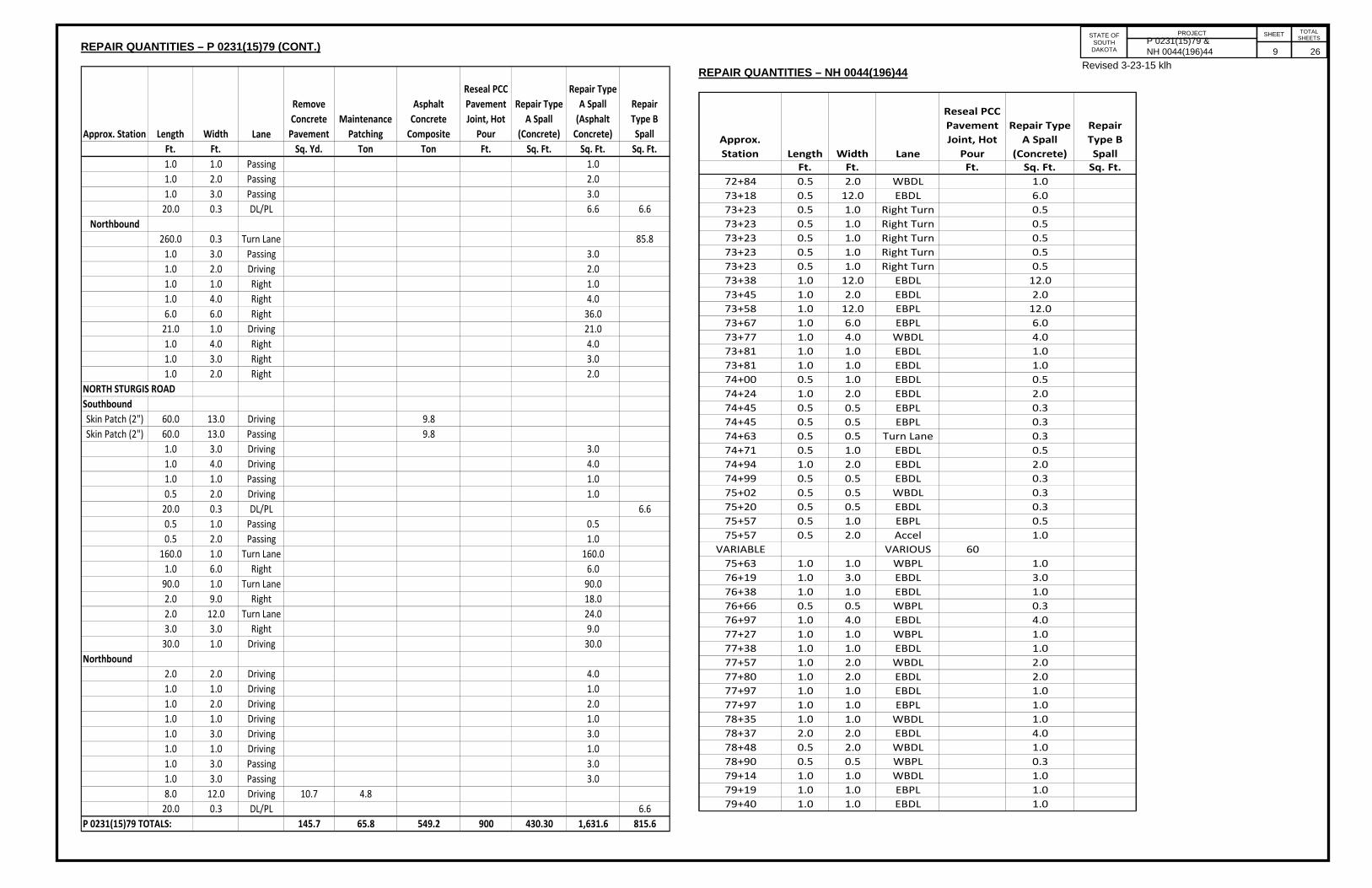
REPAIR QUANTITIES – P 0231(15)79
Approx. Station Length Width Lane
Remove Concrete Pavement
Maintenance Patching
Asphalt Concrete Composite
Reseal PCC Pavement Joint, Hot
Pour
Repair Type A Spall
(Concrete)
Repair Type A Spall (Asphalt Concrete)
Repair Type B Spall
Ft. Ft. Sq. Yd. Ton Ton Ft. Sq. Ft. Sq. Ft. Sq. Ft.VARIOUS 60
0+85 1.0 1.0 WBPL 1.00+85 1.0 1.0 WBDL 1.01+03 1.0 2.0 WBPL 2.01+20 2.0 10.0 WBPL 20.01+97 2.0 12.0 WBPL 24.02+12 1.0 10.0 WBDL 10.02+27 1.0 1.0 WBDL 1.02+46 1.0 2.0 WBDL 2.02+64 1.0 2.0 WBDL 2.03+06 2.0 2.0 Right Turn 4.03+20 1.0 3.0 WBPL 3.04+23 2.0 8.0 EBDL 16.04+55 1.0 10.0 WBDL 10.04+55 1.0 10.0 WBPL 10.04+64 6.0 6.0 EBDL 36.04+73 1.0 1.0 WBPL 1.04+73 3.0 4.0 WBPL 12.04+81 1.0 1.0 EBPL 1.04+81 1.0 1.0 EBPL 1.04+81 1.0 1.0 EBPL 1.04+81 1.0 1.0 EBPL 1.04+81 26.0 1.0 EBPL 26.04+91 1.0 1.0 EBDL 1.04+99 150.0 1.0 WBDL 150.04+99 150.0 1.0 WBPL 150.04+99 130.0 1.0 Turn Lane 130.04+99 20.0 1.0 Right Turn 20.05+00 1.0 1.0 EBDL 1.05+18 1.0 2.0 WBPL 2.05+18 2.0 2.0 EBPL 4.05+18 1.0 6.0 EBDL 6.05+18 1.0 8.0 EBDL 8.05+37 1.0 1.0 Turn Lane 1.05+37 1.0 1.0 EBDL 1.05+56 1.0 10.0 WBDL 10.05+56 0.5 1.0 WBPL 0.55+57 0.5 1.0 EBDL 0.55+57 0.5 0.5 EBPL 0.35+57 187.0 1.0 EBDL 187.05+77 1.0 8.0 Accel 8.05+77 0.5 12.0 EBDL 6.0
VARIABLE VARIOUS 605+95 1.0 1.0 Turn Lane 1.0
Approx. Station Length Width Lane
Remove Concrete Pavement
Maintenance Patching
Asphalt Concrete Composite
Reseal PCC Pavement Joint, Hot
Pour
Repair Type A Spall
(Concrete)
Repair Type A Spall (Asphalt Concrete)
Repair Type B Spall
Ft. Ft. Sq. Yd. Ton Ton Ft. Sq. Ft. Sq. Ft. Sq. Ft.5+95 1.0 1.0 WBDL 1.05+96 1.0 3.0 EBDL 3.06+15 1.0 1.0 Turn Lane 1.06+16 0.5 5.0 Accel 2.56+34 1.0 1.0 Turn Lane 1.06+34 0.5 2.0 WBDL 1.06+35 0.5 0.5 EBPL 0.36+41 5.0 1.0 Accel 5.06+53 5.0 12.0 Turn Lane 60.06+64 0.5 3.0 EBPL 1.56+66 0.5 3.0 Accel 1.56+75 40.0 Turn Lane 10.06+75 1.0 1.0 Accel 1.06+85 0.5 1.0 Accel 0.56+92 1.0 2.0 Turn Lane 2.06+92 1.0 2.0 WBDL 2.07+11 20.0 2.0 Turn Lane 4.4 2.07+13 0.5 3.0 Accel 1.57+21 0.5 0.5 Accel 0.37+55 1.0 1.0 WBPL 1.07+55 1.0 1.0 WBPL 1.07+78 0.5 0.5 EBPL 0.38+05 60.0 WBDL 15.010+41 0.5 1.0 WBDL 0.5
VARIABLE VARIOUS 6011+00 1.0 1.0 WBPL 1.011+00 1.0 2.0 WBDL 2.011+37 2.0 2.0 WBDL 4.011+37 30.0 WBDL 7.511+65 1.0 1.0 WBPL 1.011+65 1.0 1.0 WBPL 1.011+65 1.0 1.0 WBPL 1.012+02 1.0 5.0 WBDL 5.012+02 0.5 10.0 WBDL 5.012+09 2.0 2.0 WBDL 4.012+17 1.0 3.0 WBDL 3.013+35 200.0 Turn Lane 50.014+04 40.0 WBPL 10.014+28 0.5 0.5 EBDL 0.314+28 0.5 0.5 EBDL 0.314+28 0.5 0.5 EBPL 0.314+28 0.5 0.5 EBPL 0.314+49 0.5 6.0 EBDL 3.014+59 1.0 1.0 WBDL 1.0
P 0231(15)79 & NH 0044(196)44 5 26

PROJECT STATE OF SOUTH
DAKOTA
SHEET
TOTAL SHEETS
REPAIR QUANTITIES – P 0231(15)79 (CONT.)
Approx. Station Length Width Lane
Remove Concrete Pavement
Maintenance Patching
Asphalt Concrete Composite
Reseal PCC Pavement Joint, Hot
Pour
Repair Type A Spall
(Concrete)
Repair Type A Spall (Asphalt Concrete)
Repair Type B Spall
Ft. Ft. Sq. Yd. Ton Ton Ft. Sq. Ft. Sq. Ft. Sq. Ft.15+25 40.0 EBDL 10.0
VARIABLE VARIOUS 6016+43 0.5 4.0 EBDL 2.016+72 150.0 Turn Lane 37.517+04 0.5 3.0 EBDL 1.519+21 1.0 1.0 WBDL 1.019+32 1.0 1.0 WBDL 1.019+32 1.0 1.0 WBDL 1.0
VARIABLE VARIOUS 6021+34 2.0 3.0 WBPL 6.021+34 0.5 0.5 WBDL 0.321+34 0.5 0.5 WBDL 0.321+49 1.0 1.0 WBPL 1.021+65 1.0 1.0 WBPL 1.022+46 0.5 2.0 EBDL 1.022+50 1.0 3.0 Turn Lane 3.022+57 0.5 2.0 EBPL 1.023+40 15.0 Turn Lane 0.0 3.825+09 0.5 6.0 EBDL 3.025+09 0.5 1.0 EBPL 0.525+16 1.0 2.0 WBPL 2.025+67 0.5 1.0 EBDL 0.525+67 0.5 1.0 EBPL 0.525+77 40.0 WBPL 10.025+77 50.0 WBDL 12.525+86 1.0 1.0 EBPL 1.0
VARIABLE VARIOUS 6026+72 60.0 Turn Lane 0.0 15.027+69 1.0 2.0 EBDL 2.027+99 20.0 Turn Lane 5.028+28 1.0 1.0 EBDL 1.028+68 1.0 6.0 EBPL 6.029+15 1.0 1.0 WBPL 1.029+50 1.0 1.0 EBPL 1.030+18 2.0 4.0 WBDL 8.030+18 0.5 6.0 EBPL 3.030+18 0.5 2.0 EBDL 1.030+51 12.0 WBPL 3.030+51 20.0 WBDL 5.030+63 1.0 1.0 WBDL 1.030+85 120.0 CENTER 0.0 30.030+85 2.0 10.0 WBDL 20.0
VARIABLE VARIOUS 6031+05 0.5 1.0 EBPL 0.5
Approx. Station Length Width Lane
Remove Concrete Pavement
Maintenance Patching
Asphalt Concrete Composite
Reseal PCC Pavement Joint, Hot
Pour
Repair Type A Spall
(Concrete)
Repair Type A Spall (Asphalt Concrete)
Repair Type B Spall
Ft. Ft. Sq. Yd. Ton Ton Ft. Sq. Ft. Sq. Ft. Sq. Ft.31+05 1.0 1.0 EBDL 1.031+15 1.0 1.0 Turn Lane 1.031+15 1.0 1.0 Turn Lane 1.031+76 1.0 1.0 WBPL 1.032+16 0.5 12.0 EBDL 6.032+16 0.5 2.0 EBPL 1.032+35 0.5 4.0 EBDL 2.032+65 140.0 Turn Lane 35.032+72 0.5 0.5 EBDL 0.332+95 0.5 2.0 EBPL 1.032+95 0.5 0.5 EBPL 0.334+28 1.0 1.0 WBDL 1.035+12 0.5 2.0 EBPL 1.035+22 40.0 WBDL 10.035+22 20.0 WBPL 5.035+52 0.5 2.0 EBPL 1.0
VARIABLE VARIOUS 6036+75 1.0 1.0 EBDL 1.037+25 1.0 1.0 WBPL 1.037+26 1.0 1.0 WBPL 1.037+44 0.5 1.0 WBPL 0.539+00 0.5 1.0 WBPL 0.539+42 2.0 2.0 WBPL 4.040+69 1.0 2.0 WBPL 2.0
VARIABLE VARIOUS 6041+05 2.0 2.0 EBPL 4.041+27 1.0 1.0 EBPL 1.041+27 1.0 1.0 EBPL 1.042+28 0.5 0.5 EBDL 0.342+28 0.5 0.5 EBPL 0.342+28 1.0 20.0 Shoulder 20.042+60 1.0 1.0 WBPL 1.042+86 20.0 0.3 WBPL 5.042+86 20.0 0.3 WBDL 5.0
VARIABLE VARIOUS 6048+50 12.0 EBPL 3.048+50 30.0 EBDL 7.548+69 12.0 EBPL 3.048+69 12.0 EBDL 3.048+95 1.0 1.0 EBPL 1.049+60 100.0 WBDL 25.049+60 20.0 WBPL 5.050+06 0.5 3.0 EBDL 1.550+06 0.5 1.0 EBPL 0.5
P 0231(15)79 & NH 0044(196)44 6 26

PROJECT STATE OF SOUTH
DAKOTA
SHEET
TOTAL SHEETS
REPAIR QUANTITIES – P 0231(15)79 (CONT.)
Approx. Station Length Width Lane
Remove Concrete Pavement
Maintenance Patching
Asphalt Concrete Composite
Reseal PCC Pavement Joint, Hot
Pour
Repair Type A Spall
(Concrete)
Repair Type A Spall (Asphalt Concrete)
Repair Type B Spall
Ft. Ft. Sq. Yd. Ton Ton Ft. Sq. Ft. Sq. Ft. Sq. Ft.50+64 0.5 15.0 EBDL 7.550+64 1.0 1.0 EBPL 1.050+84 0.5 12.0 EBDL 6.050+84 0.5 12.0 EBPL 6.0
VARIABLE VARIOUS 6051+05 0.5 3.0 EBDL 1.551+05 0.5 1.0 EBPL 0.551+19 1.0 3.0 EBPL 3.051+45 0.5 2.0 EBPL 1.051+80 1.0 1.0 WBPL 1.052+05 1.0 1.0 EBDL 1.052+45 0.5 6.0 EBDL 3.052+82 30.0 EBDL 7.553+15 40.0 Center 10.053+52 1.0 3.0 EBPL 3.053+55 20.0 Turn Lane 5.053+66 1.0 1.0 EBPL 1.054+32 0.5 0.5 WBPL 0.354+75 100.0 Turn Lane 25.055+47 0.5 0.5 EBPL 0.355+67 0.5 0.5 EBPL 0.355+87 0.5 0.5 EBPL 0.3
VARIABLE VARIOUS 6056+60 1.0 1.0 WBDL 1.056+60 1.0 1.0 WBDL 1.056+60 1.0 1.0 WBPL 1.056+60 1.0 1.0 WBPL 1.056+93 1.0 1.0 Accel 1.057+36 40.0 Turn Lane 0.057+45 1.0 1.0 WBPL 1.057+50 2.0 3.0 WBDL 6.057+50 1.0 1.0 WBPL 1.057+85 1.0 1.0 WBPL 1.057+95 1.0 1.0 WBPL 1.058+36 0.5 1.0 Turn Lane 0.558+57 0.5 3.0 Turn Lane 1.558+65 60.0 6.0 Accel 40.0 18.159+23 1.0 1.0 WBDL 1.059+23 1.0 1.0 WBDL 1.059+23 1.0 1.0 WBDL 1.059+45 15.0 12.0 WBDL 20.0 9.059+57 0.5 12.0 Turn Lane 6.059+79 0.5 1.0 EBDL 0.559+92 30.0 12.0 Accel 40.0 18.1
Approx. Station Length Width Lane
Remove Concrete Pavement
Maintenance Patching
Asphalt Concrete Composite
Reseal PCC Pavement Joint, Hot
Pour
Repair Type A Spall
(Concrete)
Repair Type A Spall (Asphalt Concrete)
Repair Type B Spall
Ft. Ft. Sq. Yd. Ton Ton Ft. Sq. Ft. Sq. Ft. Sq. Ft.59+98 1.0 1.0 WBDL 1.060+14 1.0 1.0 WBPL 1.060+38 1.0 1.0 Turn Lane 1.060+65 1.0 10.0 WBDL 10.060+95 Start Overlay61+14 0.5 0.5 EBDL 0.361+35 1.0 1.0 Turn Lane 1.061+55 1.0 1.0 EBPL 1.062+95 300.0 EBDL/PL 75.063+22 1.0 1.0 EBPL 1.063+87 0.5 4.0 EBDL 2.064+00 0.5 2.0 EBPL 1.064+05 1.0 15.0 EBDL 15.064+11 1.0 1.0 WBPL 1.064+11 1.0 3.0 WBPL 3.064+20 0.5 0.5 EBPL 0.364+36 1.0 50.0 EBDL 50.064+60 1.0 1.0 WBPL 1.064+65 1.0 1.0 WBPL 1.0
VARIABLE VARIOUS 6065+55 200.0 0.3 EBDL/PL 66.065+70 1.0 3.0 WBDL 3.066+14 1.0 12.0 WBPL 12.066+34 1.0 12.0 WBDL 12.066+34 1.0 12.0 WBPL 12.066+50 1.0 3.0 WBDL 3.066+88 0.5 0.5 WBPL 0.366+88 End Overlay67+06 1.0 1.0 WBPL 1.067+25 24.0 0.3 WBDL/PL 7.967+35 200.0 0.3 EBDL/PL 66.067+45 24.0 0.3 WBDL/PL 7.967+68 0.5 3.0 WBDL 1.568+08 1.0 1.0 EBDL 1.068+08 0.5 3.0 WBPL 1.5
Equation 68+21.57 Bk = 64+14.63 Ah64+22 0.5 12.0 WBPL 6.064+43 0.5 12.0 WBPL 6.064+63 0.5 0.5 WBDL 0.364+80 0.5 2.0 WBDL 1.064+80 0.5 0.5 WBDL 0.364+81 1.0 1.0 EBPL 1.064+89 0.5 3.0 EBPL 1.564+90 1.0 1.0 WBDL 1.0
529.6
P 0231(15)79 & NH 0044(196)44 7 26

PROJECT STATE OF SOUTH
DAKOTA
SHEET
TOTAL SHEETS
REPAIR QUANTITIES – P 0231(15)79 (CONT.)
Approx. Station Length Width Lane
Remove Concrete Pavement
Maintenance Patching
Asphalt Concrete Composite
Reseal PCC Pavement Joint, Hot
Pour
Repair Type A Spall
(Concrete)
Repair Type A Spall (Asphalt Concrete)
Repair Type B Spall
Ft. Ft. Sq. Yd. Ton Ton Ft. Sq. Ft. Sq. Ft. Sq. Ft.64+99 0.5 0.5 EBPL 0.365+10 0.5 1.0 WBPL 0.565+17 1.0 1.0 WBDL 1.065+17 1.0 1.0 WBPL 1.065+17 1.0 1.0 EBPL 1.065+30 2.0 2.0 WBDL 4.065+42 20.0 0.3 WBDL 6.6
VARIABLE VARIOUS 6065+82 1.0 3.0 EBDL 3.065+93 1.0 1.0 EBDL 1.066+02 1.0 1.0 EBPL 1.066+20 1.0 3.0 EBDL 3.066+31 1.0 1.0 WBPL 1.066+31 2.0 2.0 WBDL 4.066+31 0.5 6.0 EBDL 3.069+39 1.0 2.0 WBPL 2.069+78 0.5 0.5 EBPL 0.369+78 4.0 4.0 EBDL 16.069+78 0.5 0.5 EBPL 0.369+94 0.5 12.0 EBPL 6.070+05 1.0 1.0 EBPL 1.070+09 20.0 0.3 WBPL 6.670+27 20.0 0.3 WBPL 6.670+27 1.0 1.0 EBDL 1.070+33 0.5 2.0 EBPL 1.070+34 2.0 2.0 WBDL 4.070+49 10.0 0.3 WBDL 3.370+52 1.0 12.0 EBDL 12.0
VARIABLE VARIOUS 6070+70 1.0 1.0 EBDL 1.070+70 1.0 1.0 EBDL 1.070+80 0.5 4.0 EBPL 2.070+83 1.0 2.0 WBDL 2.071+03 1.0 12.0 Center 12.071+03 12.0 12.0 EBPL 16.0 7.271+30 1.0 1.0 EBDL 1.071+38 0.5 2.0 EBPL 1.071+40 2.0 4.0 WBDL 8.071+40 40.0 0.3 WBDL 13.271+48 1.0 2.0 EBDL 2.071+52 1.0 1.0 Center 1.071+58 4.0 8.0 EBDL 32.071+58 4.0 12.0 EBPL 5.3 2.471+60 1.0 1.0 WBPL 1.0
Approx. Station Length Width Lane
Remove Concrete Pavement
Maintenance Patching
Asphalt Concrete Composite
Reseal PCC Pavement Joint, Hot
Pour
Repair Type A Spall
(Concrete)
Repair Type A Spall (Asphalt Concrete)
Repair Type B Spall
Ft. Ft. Sq. Yd. Ton Ton Ft. Sq. Ft. Sq. Ft. Sq. Ft.71+60 1.0 2.0 WBDL 2.071+60 1.0 1.0 WBDL 1.071+73 1.0 1.0 EBPL 1.071+73 40.0 0.3 EBPL 13.271+80 0.5 0.5 WBDL 0.371+82 4.0 12.0 EBPL 5.3 2.471+82 2.0 4.0 Right Turn 8.071+99 3.0 12.0 EBPL 4.0 1.872+00 1.0 3.0 WBDL 3.072+00 1.0 1.0 WBPL 1.072+27 1.0 1.0 WBPL 1.072+27 1.0 8.0 WBDL 8.072+38 1.0 10.0 EBDL 10.0
NORTH DEADWOOD AVENUESouthbound
1.0 1.0 Turn Lane 1.01.0 1.0 Thru 1.01.0 3.0 Turn Lane 3.02.0 4.0 Turn Lane 8.01.0 1.0 Turn Lane 1.01.0 3.0 Turn Lane 3.01.0 1.0 Thru 1.00.5 1.0 Thru 0.50.5 1.0 Thru 0.50.5 6.0 Thru 3.0
Northbound 0.040.0 0.3 13.21.0 3.0 Right 3.01.0 1.0 Right 1.01.0 1.0 Right 1.01.0 1.0 Right 1.0
120.0 0.3 Left 39.6 39.61.0 10.0 Left 10.01.0 1.0 Left 1.01.0 1.0 Left 1.01.0 1.0 Left 1.020.0 0.3 Left 6.6 6.6
SOUTH STURGIS ROADSouthbound
1.0 10.0 Driving 10.01.0 1.0 Driving 1.01.0 1.0 Passing 1.00.5 1.0 Passing 0.50.5 1.0 Passing 0.5
P 0231(15)79 & NH 0044(196)44 8 26
PROJECT STATE OF SOUTH
DAKOTA
SHEET
TOTAL SHEETS
Revised 3-23-15 klh
REPAIR QUANTITIES – P 0231(15)79 (CONT.)
Approx. Station Length Width Lane
Remove Concrete Pavement
Maintenance Patching
Asphalt Concrete Composite
Reseal PCC Pavement Joint, Hot
Pour
Repair Type A Spall
(Concrete)
Repair Type A Spall (Asphalt Concrete)
Repair Type B Spall
Ft. Ft. Sq. Yd. Ton Ton Ft. Sq. Ft. Sq. Ft. Sq. Ft.1.0 1.0 Passing 1.01.0 2.0 Passing 2.01.0 3.0 Passing 3.020.0 0.3 DL/PL 6.6 6.6
Northbound260.0 0.3 Turn Lane 85.81.0 3.0 Passing 3.01.0 2.0 Driving 2.01.0 1.0 Right 1.01.0 4.0 Right 4.06.0 6.0 Right 36.021.0 1.0 Driving 21.01.0 4.0 Right 4.01.0 3.0 Right 3.01.0 2.0 Right 2.0
NORTH STURGIS ROADSouthboundSkin Patch (2") 60.0 13.0 Driving 9.8Skin Patch (2") 60.0 13.0 Passing 9.8
1.0 3.0 Driving 3.01.0 4.0 Driving 4.01.0 1.0 Passing 1.00.5 2.0 Driving 1.020.0 0.3 DL/PL 6.60.5 1.0 Passing 0.50.5 2.0 Passing 1.0
160.0 1.0 Turn Lane 160.01.0 6.0 Right 6.090.0 1.0 Turn Lane 90.02.0 9.0 Right 18.02.0 12.0 Turn Lane 24.03.0 3.0 Right 9.030.0 1.0 Driving 30.0
Northbound2.0 2.0 Driving 4.01.0 1.0 Driving 1.01.0 2.0 Driving 2.01.0 1.0 Driving 1.01.0 3.0 Driving 3.01.0 1.0 Driving 1.01.0 3.0 Passing 3.01.0 3.0 Passing 3.08.0 12.0 Driving 10.7 4.820.0 0.3 DL/PL 6.6
P 0231(15)79 TOTALS: 145.7 65.8 549.2 900 430.30 1,631.6 815.6
REPAIR QUANTITIES – NH 0044(196)44
Approx. Station Length Width Lane
Reseal PCC Pavement Joint, Hot
Pour
Repair Type A Spall
(Concrete)
Repair Type B Spall
Ft. Ft. Ft. Sq. Ft. Sq. Ft.72+84 0.5 2.0 WBDL 1.073+18 0.5 12.0 EBDL 6.073+23 0.5 1.0 Right Turn 0.573+23 0.5 1.0 Right Turn 0.573+23 0.5 1.0 Right Turn 0.573+23 0.5 1.0 Right Turn 0.573+23 0.5 1.0 Right Turn 0.573+38 1.0 12.0 EBDL 12.073+45 1.0 2.0 EBDL 2.073+58 1.0 12.0 EBPL 12.073+67 1.0 6.0 EBPL 6.073+77 1.0 4.0 WBDL 4.073+81 1.0 1.0 EBDL 1.073+81 1.0 1.0 EBDL 1.074+00 0.5 1.0 EBDL 0.574+24 1.0 2.0 EBDL 2.074+45 0.5 0.5 EBPL 0.374+45 0.5 0.5 EBPL 0.374+63 0.5 0.5 Turn Lane 0.374+71 0.5 1.0 EBDL 0.574+94 1.0 2.0 EBDL 2.074+99 0.5 0.5 EBDL 0.375+02 0.5 0.5 WBDL 0.375+20 0.5 0.5 EBDL 0.375+57 0.5 1.0 EBPL 0.575+57 0.5 2.0 Accel 1.0
VARIABLE VARIOUS 6075+63 1.0 1.0 WBPL 1.076+19 1.0 3.0 EBDL 3.076+38 1.0 1.0 EBDL 1.076+66 0.5 0.5 WBPL 0.376+97 1.0 4.0 EBDL 4.077+27 1.0 1.0 WBPL 1.077+38 1.0 1.0 EBDL 1.077+57 1.0 2.0 WBDL 2.077+80 1.0 2.0 EBDL 2.077+97 1.0 1.0 EBDL 1.077+97 1.0 1.0 EBPL 1.078+35 1.0 1.0 WBDL 1.078+37 2.0 2.0 EBDL 4.078+48 0.5 2.0 WBDL 1.078+90 0.5 0.5 WBPL 0.379+14 1.0 1.0 WBDL 1.079+19 1.0 1.0 EBPL 1.079+40 1.0 1.0 EBDL 1.0
P 0231(15)79 & NH 0044(196)44 9 26

PROJECT STATE OF SOUTH
DAKOTA
SHEET
TOTAL SHEETS
REPAIR QUANTITIES – NH 0044(196)44 (CONT.)
Approx. Station Length Width Lane
Reseal PCC Pavement Joint, Hot
Pour
Repair Type A Spall
(Concrete)
Repair Type B Spall
Ft. Ft. Ft. Sq. Ft. Sq. Ft.79+72 0.5 0.5 EBDL 0.379+87 1.0 8.0 EBDL 8.080+51 1.0 1.0 WBDL 1.0
VARIABLE VARIOUS 60 0.080+81 1.0 1.0 EBDL 1.080+85 1.0 5.0 WBDL 5.080+93 1.0 1.0 WBPL 1.081+47 1.0 1.0 WBDL 1.081+47 0.5 0.5 WBPL 0.382+07 0.5 1.0 EBDL 0.582+17 0.5 8.0 WBDL 4.083+48 1.0 1.0 EBDL 1.083+60 0.5 0.5 WBPL 0.383+99 1.0 1.0 WBDL 1.083+99 0.5 0.5 WBPL 0.383+99 1.0 1.0 EBPL 1.084+19 0.5 1.0 EBPL 0.584+39 1.0 1.0 EBPL 1.084+74 1.0 1.0 WBDL 1.084+98 1.0 1.0 WBDL 1.085+12 0.5 0.5 WBDL 0.3
VARIABLE VARIOUS 6085+80 5.0 0.5 WBDL 2.585+98 0.5 0.5 EBPL 0.385+98 0.5 0.5 WBPL 0.385+98 0.5 0.5 WBDL 0.386+29 10.0 EBPL 386+38 1.0 2.0 WBDL 2.086+38 20.0 WBPL 5.086+44 0.5 0.5 WBDL 0.386+98 1.0 1.0 WBDL 1.087+18 1.0 1.0 WBPL 1.087+37 0.5 5.0 EBPL 2.588+79 0.5 5.0 EBPL 2.588+99 0.5 5.0 EBPL 2.588+99 1.0 4.0 WBPL 4.088+99 0.5 2.0 Center 1.089+53 1.0 2.0 EBPL 2.089+57 1.0 1.0 WBDL 1.089+57 1.0 1.0 EBDL 1.0
Approx. Station Length Width Lane
Reseal PCC Pavement Joint, Hot
Pour
Repair Type A Spall
(Concrete)
Repair Type B Spall
Ft. Ft. Ft. Sq. Ft. Sq. Ft.89+59 0.5 0.5 WBDL 0.390+19 2.0 2.0 EBPL 4.090+33 1.0 1.0 EBDL 1.0
VARIABLE VARIOUS 60 0.091+35 0.5 0.5 WBDL 0.391+59 1.0 2.0 WBPL 2.091+95 0.5 0.5 WBDL 0.392+50 0.5 1.0 WBDL 0.592+82 1.0 1.0 Center 1.092+82 20.0 5.092+82 6.0 1.593+41 0.5 0.5 WBDL 0.393+79 2.0 2.0 EBDL 4.094+00 0.5 1.0 WBPL 0.594+25 1.0 1.0 WBDL 1.094+39 2.0 2.0 EBPL 4.094+79 1.0 1.0 WBDL 1.095+35 0.5 2.0 WBPL 1.0
VARIABLE VARIOUS 60 0.096+45 1.0 1.0 EBPL 1.096+45 1.0 3.0 EBDL 3.096+75 1.0 4.0 EBPL 4.097+17 0.5 6.0 WBPL 3.097+36 6.0 WBPL 1.597+46 0.5 0.5 WBDL 0.398+35 0.5 0.5 WBPL 0.398+63 0.5 0.5 WBDL 0.398+63 1.0 2.0 WBPL 2.098+63 0.5 2.0 EBDL 1.098+63 20.0 5.098+96 2.0 5.0 WBDL 10.098+96 10.0 2.599+36 0.5 3.0 EBDL 1.599+36 0.5 2.0 EBPL 1.099+36 1.0 1.0 WBPL 1.099+36 60.0 0.0 15.099+56 1.0 1.0 WBDL 1.0100+08 11.0 WBPL 0.0 2.8VARIABLE VARIOUS 60101+51 1.0 1.0 WBDL 1.0
Approx. Station Length Width Lane
Reseal PCC Pavement Joint, Hot
Pour
Repair Type A Spall
(Concrete)
Repair Type B Spall
Ft. Ft. Ft. Sq. Ft. Sq. Ft.102+43 0.5 0.5 WBPL 0.3102+83 2.0 2.0 WBPL 4.0102+83 1.0 1.0 EBPL 1.0103+03 1.0 1.0 EBDL 1.0103+03 1.0 1.0 EBDL 1.0103+22 1.0 1.0 WBPL 1.0103+22 1.0 1.0 WBDL 1.0103+23 1.0 1.0 WBPL 1.0103+23 1.0 1.0 WBDL 1.0103+88 1.0 2.0 WBDL 2.0103+88 0.5 1.0 WBPL 0.5104+28 2.0 2.0 EBDL 4.0104+40 1.0 1.0 WBDL 1.0104+59 2.0 2.0 EBDL 4.0104+59 0.5 0.5 EBDL 0.3104+85 0.5 0.5 WBDL 0.3105+33 1.0 1.0 WBPL 1.0105+62 0.5 0.5 Center 0.3105+62 0.5 0.5 EBPL 0.3
200.0 Center 50.0Transverse Joints 10176
NH 0044(196)44 TOTALS: 10,536 212.7 90.8
P 0231(15)79 & NH 0044(196)44 10 26

PROJECT STATE OF SOUTH
DAKOTA
SHEET
TOTAL SHEETS
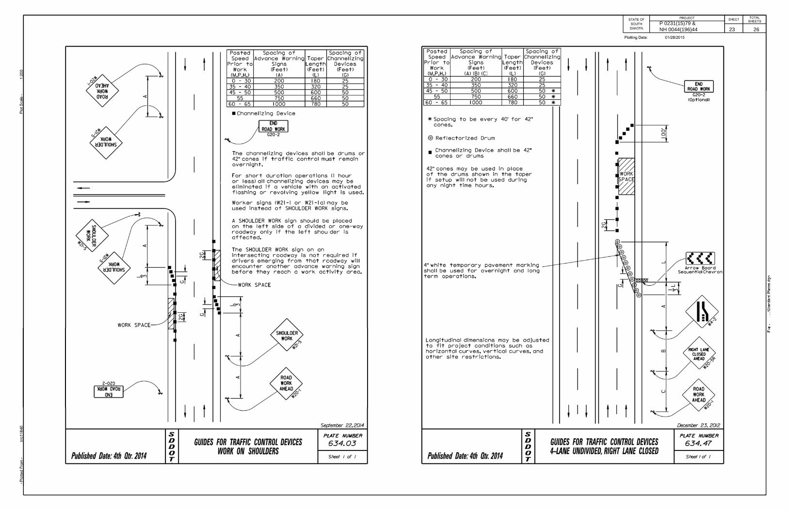
TRAFFIC CONTROL – GENERAL NOTES
1. Requests to deviate from the sequence of operations shall be submitted in writing to the Engineer for review. Approval of an alternate sequence of operations will only be allowed when the proposed changes meet with the Department’s intent for traffic control and sequencing of the work. An alternate sequence shall be submitted for review a minimum of one week prior to potential implementation.
2. Unless otherwise stated in these plans, no work will be allowed
during hours of darkness. Hours of darkness are defined as ½ hour after sunset until ½ hour before sunrise.
3. Storage of vehicles and equipment shall be as near the right-of-way
as possible. Contractor’s employees should mobilize at a location off the right-of-way and arrive at the work sites in a minimum number of vehicles necessary to perform the work. Indiscriminate driving and parking of vehicles within the right-of-way will not be permitted. Any damage of the vegetation, surfacing, embankment, delineators, and existing signs resulting from such indiscriminate use shall be repaired and/or restored by the Contractor, at no expense to the State, and to the satisfaction of the Engineer.
4. Existing guide, route, informational logo, regulatory, warning signs and delineation shall be temporarily reset and maintained during construction as directed by the Engineer. Removing, relocating, salvaging and resetting of the above items shall be the responsibility of the Contractor.
5. Construction signing mounted on portable supports shall not be used for a duration of more than 3 days, unless approved by the Engineer. Construction signing that remains in the same location for more than 3 days shall be mounted on fixed location, ground mounted, breakaway supports.
6. The quantity of traffic control units paid for will be for the greatest number of installations per sign in place at any one time regardless of the number of set-ups per project.
7. Any delineators and signs damaged or lost shall be replaced by the Contractor at no cost to the State.
8. All materials and equipment shall be stored a minimum distance of
30’ from the traveled way during nonworking hours.
9. The Contractor shall provide documentation that all breakaway sign supports comply with FHWA NCHRP 350 or MASH crash-worthy requirements. The Contractor shall provide installation details at the preconstruction meeting for all breakaway sign support assemblies.
10. The Contractor shall be required to have a person available 24
hour/day, 7 days/week to maintain traffic control devices. The name and cellular telephone number of this individual shall be given to the Engineer at the preconstruction meeting.
11. The Contractor or designated traffic control subcontractor shall make night inspections at the initial set up of traffic control and every week thereafter to ensure the adequacy, legibility and reflectivity of each sign and device. A written summary of each inspection shall be given to the Engineer within 24 hours after completion of the inspection. The cost for the nighttime inspection work shall be incidental to the contract lump sum price for “Traffic Control, Miscellaneous”.
12. Vehicles working in traffic or alongside traffic shall be equipped with a flashing amber light visible from all directions. The amber light shall be mounted on the uppermost part of the Contractor’s vehicle. Lights must have peak intensity within the range of 40 to 400 candelas and must flash at 75 ± 15 flashes per minute. Vehicle flasher/hazard lights are not acceptable. All haul trucks shall be equipped with a second flashing amber light that is visible from the backside of the haul truck. The costs for the flashing amber lights shall be incidental to the various related contract bid items.
13. All construction operations shall be conducted in the general direction of traffic movement.
14. If there is a discrepancy between the traffic control plans, standard
plates, and the MUTCD – whichever is more stringent shall be used, as determined by the Engineer.
15. Temporary Road Markers (Tabs) shall be used for lane closure tapers or lane shift tapers and shall be installed at 5’ spacing. Tabs used for tapers and shifts will not be measured for payment. All costs associated to furnish, install, maintain (including replacement as required by the Engineer at no added cost to the Department), and remove all markers will be incidental to the contract lump sum price for “Traffic Control, Miscellaneous”.
16. Drums are required in all lane closure tapers.
17. Signal timing may need to be adjusted during construction. The Engineer will coordinate with the Region Traffic Engineer for timing adjustments.
PROJECT OVERVIEW NOTE: The quantities listed by stationing in these plans may vary from actual field quantities.
West of Sturgis Road (Sta. 0+85) to east of Sturgis Road (Sta. 7+21) o Reseal PCC Pavement Joint, Hot Pour o Repair Type B Spall o Maintenance Patching (Full Depth Repair) o Repair Type A Spall (Asphalt Patching Material)
East of Sturgis Road (Sta. 7+21) to West of Deadwood Avenue (Sta.
60+95) o Reseal PCC Pavement Joint, Hot Pour o Repair Type B Spall o Maintenance Patching (Full Depth Repair) o Repair Type A Spall (Concrete Patching Material)
West of Deadwood Avenue (Sta. 60+95) to east of Deadwood
Avenue (Sta. 66+88) o Reseal PCC Pavement Joint, Hot Pour o Repair Type B Spall o Repair Type A Spall (Asphalt Patching Material) o 1.5” Asphalt Concrete Composite Overlay
East of Deadwood Avenue (Sta.66+88) to Mountain View Rd.
(Sta.72+57) o Reseal PCC Pavement Joint, Hot Pour o Repair Type B Spall o Repair Type A Spall (Concrete Patching Material) o Maintenance Patching (Full Depth Repair)
North Deadwood Avenue
o Repair Type B Spall o Repair Type A Spall (Asphalt Patching Material)
South Sturgis Road
o Repair Type B Spall o Repair Type A Spall (Asphalt Patching Material)
North Sturgis Road
o Repair Type B Spall o Maintenance Patching (Full Depth Repair and Skin Patch) o Repair Type A Spall (Asphalt Patching Material)
Mountain View Rd. (Sta.72+57) to west of 12th Street (Sta. 105+88)
o Reseal PCC Pavement Joint, Hot Pour o Repair Type B Spall o Repair Type A Spall (Concrete Patching Material)
P 0231(15)79 & NH 0044(196)44 11 26

PROJECT STATE OF SOUTH
DAKOTA
SHEET
TOTAL SHEETS
SEQUENCE OF OPERATIONS The Contractor shall provide a Sequence of Operations, at least one week in advance of the preconstruction meeting, to the Engineer for approval. The following restrictions shall apply:
1 – 1000’ lane closure in each direction for the entire project length (both projects) on Omaha/West Chicago – 1000’ does not include the tapers.
Intersection work at Sturgis Road/West Chicago shall be done at night. Lane closures for this work will only be allowed from 6:00 pm until 6:00 am. Intersection work shall be from Sta. 7+21 to 0+85 on West Chicago and includes both legs of Sturgis Road. All traffic control devices shall be removed from the roadway by 6:00 am.
The West Chicago portion of the intersection of Deadwood Avenue/West Chicago shall be done at night. Lane closures for this work will only be allowed from 6:00 pm until 6:00 am. Intersection work shall be from Sta. 60+95 to 66+88 on West Chicago. All traffic control devices shall be removed from the roadway by 6:00 am.
Only two lane closure setups will be paid for regardless of where or when they are used. A lane closure setup is as described above.
One lane of traffic on each leg of the intersections shall be maintained at all times during intersection night work.
The traffic signals shall be set to flashing red during intersection night work.
Standard Plates shown in these plans shall be used for traffic control. TYPE C ADVANCE WARNING ARROW PANEL The quantity of Type C Advance Warning Arrow Panels paid will be the most installations in place at any one time regardless of the number of setups per project. TEMPORARY PAVEMENT MARKING (TABS) Temporary pavement marking tabs shall be used on the top of the asphalt concrete overlay and as directed by the Engineer. Tabs shall be used for edge lines, centerlines, lane lines, skips, and as directed by the Engineer. Tabs shall be spaced at 5’. Tabs shall be installed prior to opening the lanes to traffic. Tabs shall be removed the same day that permanent pavement marking is installed. Any marking covered or damaged shall be replaced prior to the end of the day at no cost to the State. All costs for furnishing, installing, and removing the tabs when no longer needed shall be included in the contract unit price per foot for Temporary Pavement Marking. PRESS RELEASE ANNOUNCEMENTS The SDDOT will prepare a Press Release to be released 5 days prior to any phase change or any other major change that affects traffic flow. The SDDOT will be responsible to keep law enforcement, emergency services, and the traveling public notified of changes in project access. The Contractor shall provide the Engineer with pertinent information 7 days prior to any phase change or any other major changes that affect traffic flow.
CONTRACTOR FURNISHED PROGRESS SCHEDULES The Contractor shall furnish the Engineer two copies of a bar chart method progress schedule at the preconstruction meeting. The schedule shall consist of a construction schedule and brief written narrative. The schedule shall contain the following information:
1. A time scale to graphically show percentage of work scheduled for completion within the contract completion requirements.
2. Definition and relation of work activities to contract pay items. 3. Work activities (prime contractor and all subcontractor activities) in
the order they will be performed including submittals, approvals, deliveries, temporary traffic control, and permanent signing/striping.
4. All major work activities that are controlling factors in the completion of the work.
5. The time required for each activity and its relationship in time to other activities.
6. The total expected time to complete all work. 7. The expected work shifts in days per week and hours per day and
the days when work is not expected to be performed. 8. Expected adverse weather delays.
The schedule shall be updated, revised and resubmitted on a bi-weekly interval until the project is substantially complete. There will be no direct payment for the contractor furnished schedule. All costs associated with the schedule shall be incidental to the related items. Failure to properly submit the required construction schedules will result in the withholding of progress payments until an approved schedule is received. CONTRACTOR FURNISHED PORTABLE CHANGEABLE MESSAGE SIGN The Contractor shall furnish portable changeable message signs to be used for the duration of the project. Message signs shall be installed to inform the traveling public of when construction will begin for each phase (2 week advance notice), advising the general public of the conditions ahead, and as directed by the Engineer. The changeable message signs shall be furnished, programmed, and maintained for the entire project duration. The Engineer will assist in determining the location and messages to be programmed into the message sign. The message signs shall be clearly visible from a minimum of 900 feet and shall be solar powered or wired directly to a power source. Diesel and gas powered message signs will not be allowed. The portable changeable message signs will be paid for at the contract unit price per each for “Contractor Furnished Portable Changeable Message Sign”. Payment will be full compensation for furnishing, maintaining, and relocating as many times as required by the Engineer and the Contractor’s operations. CONTRACTOR FURNISHED SPEED MONITORING RADAR TRAILER The Contractor shall provide 2 solar powered speed trailers to monitor traffic speeds on designated routes at locations specified in the field by the Engineer. All costs associated with furnishing, maintaining, transporting, relocating if necessary, and removing the speed trailers from locations specified by the Engineer shall be included in the contract unit price per Each for Contractor Furnished Speed Monitoring Radar Trailer.
INVENTORY OF TRAFFIC CONTROL DEVICES – PCN 05a5
SIGN CODE SIGN SIZE DESCRIPTION
NUMBER REQUIRED
UNITS PER SIGN
UNITS
G20-2 36'' x 18'' END ROAD WORK 4 17 68R10-6 36'' x 24'' STOP HERE ON RED 3 20 60W3-4 48'' x 48'' BE PREPARED TO STOP 2 34 68W4-2 48'' x 48'' LEFT OR RIGHT LANE ENDS (SYMBOL) 2 34 68W9-3 48'' x 48'' CENTER LANE CLOSED #### FT. OR AHEAD 2 34 68
W20-1 48'' x 48'' ROAD WORK #### FT. OR AHEAD 8 34 272W20-5 48'' x 48'' CENTER LANE CLOSED #### FT. OR AHEAD 2 34 68W20-5 48'' x 48'' LT. OR RT. LANE CLOSED #### FT. OR AHEAD 2 34 68W20-7 48'' x 48'' FLAGGER (SYMBOL) 4 34 136W21-5 48'' x 48'' SHOULDER WORK 2 34 68***** TYPE 3 BARRICADE - 8 FT. DOUBLE SIDED 4 56 224
TOTAL UNITS 1168 INVENTORY OF TRAFFIC CONTROL DEVICES – PCN 05a6
SIGN CODE SIGN SIZE DESCRIPTION
NUMBER REQUIRED
UNITS PER SIGN
UNITS
G20-2 36'' x 18'' END ROAD WORK 4 17 68R1-1 30'' x 30'' STOP 1 21 21W3-4 48'' x 48'' BE PREPARED TO STOP 2 34 68W4-2 48'' x 48'' LEFT OR RIGHT LANE ENDS (SYMBOL) 2 34 68W9-3 48'' x 48'' CENTER LANE CLOSED #### FT. OR AHEAD 2 34 68
W20-1 48'' x 48'' ROAD WORK #### FT. OR AHEAD 8 34 272W20-5 48'' x 48'' CENTER LANE CLOSED #### FT. OR AHEAD 2 34 68W20-5 48'' x 48'' LT. OR RT. LANE CLOSED #### FT. OR AHEAD 2 34 68W20-7 48'' x 48'' FLAGGER (SYMBOL) 4 34 136W21-5 48'' x 48'' SHOULDER WORK 2 34 68***** TYPE 3 BARRICADE - 8 FT. DOUBLE SIDED 4 56 224
TOTAL UNITS 1129
P 0231(15)79 & NH 0044(196)44 12 26

PROJECT STATE OF SOUTH
DAKOTA
SHEET
TOTAL SHEETS
PERMANENT PAVEMENT MARKINGS Included in the estimate of quantities are pavement markings for intersections of West Chicago/Sturgis Road and West Chicago/Deadwood Ave. The Engineer shall determine the extent of the markings to be placed at West Chicago/Sturgis Road due to the concrete repair. The location of the existing pavement marking shall be documented prior to removal, so that replacement can be at the existing location. Application of permanent pavement marking shall be completed within 14 calendar days following completion of the pavement repair. COLD APPLIED PLASTIC PAVEMENT MARKING The Contractor shall apply the Cold Applied Plastic Pavement Marking material as per manufacturer’s instructions. Cold applied plastic pavement markings shall be placed into a recessed groove on the surface. Final locations of markings will be determined by Engineer. GROOVE PAVEMENT FOR COLD APPLIED PLASTIC MARKINGS The grooving shall be completed within the following tolerance: Depth of Groove: 110 mils, ± 10 mils. The bottom of the groove shall be uniform and free of loose material. The groove shall be flat and of uniform depth for the entire width of the groove. Existing grooves that do not meet the 110 mil depth requirement shall be re-grooved. In areas where the existing groove depth meets the 110 mil depth requirements and portions of the existing markings are still in place, the existing markings shall be removed. All costs for materials, labor, and equipment necessary to remove the existing markings shall be incidental to the contract unit price for various Grooving for Cold Applied Plastic Marking. Markings that fall outside of the groove shall be removed (at least 90%) using additional methods approved by the Engineer. All costs for materials, labor, and equipment necessary to remove the existing markings shall be incidental to the contract unit price for various Grooving for Cold Applied Plastic Marking. The Contractor shall establish a positive means for the removal of the grinding and/or grooving residue. Solid residue shall be removed from the pavement surfaces before being blown by traffic action or wind. Residue shall not be permitted to flow across lanes being used by public traffic or into gutter or drainage facilities. Residue, whether in solid or slurry form, shall be disposed of in a manner that will prevent it from reaching any waterway in a concentrated state.
SAWED-IN, PREFORMED DETECTOR LOOPS Included in the estimate of quantities are 4 Sawed-in, Preformed Detector Loops to be used as directed by the Engineer.
P 0231(15)79 & NH 0044(196)44 13 26

DAKOTA
SOUTH
STATE OFPROJECT
SHEETSHEETS
TOTAL
SURFACING TYPICAL
...\prj\P
enn05a5 & 0
5a6\typ.d
gn
File -
Plotting Date: 03/16/2015
Plot Scale -
1:2
00
Plotted Fro
m -
trrc
11610
2’32’2’ 2’40’2’
Concrete Composite1.5" Asphalt
Concrete Composite1.5" Asphalt
2’Variable2’
60+95 to 61+77 60+95 to 62+17
Transition 61+77 to 62+37 Transition 62+17 to 62+37
12’12’12’ 8’12’12’12’
8’12’12’Variable12’12’8’
60’
Existing PCC Pavement
1.5" Asphalt Concrete Composite
1.5"
1.5" Asphalt Concrete Composite
Sta 62+37 to Sta 66+88
30’ to 9’
Begin and End of Asphalt Overlay
*** 8’ sluff at intersecting streets
P 0231(15)79 & NH 0044(196)44 14 26

HORIZONTAL ALIGNMENT DATA
The coordinates shown on this sheet are based on the South Dakota State Plane Coordinate System. South Zone (NAD 83/83); SF = 0.99978357
PROJECT STATE OF SOUTH
DAKOTA
SHEET
TOTAL SHEETS
MAINLINE
Type Station Northing EastingPOB 0+00.00 652490.683 1194218.257
TL= 2276.99 S 87°51'29" E PC 22+76.99 652405.577 1196493.658PI 25+85.98 R = 1909.86 Delta = 18°22'49" R 652394.028 1196802.432PT 28+89.66 652285.705 1197091.813
TL= 615.06 S 69°28'40" E PC 35+04.73 652070.082 1197667.844PI 37+98.43 R = 1909.86 Delta = 17°29'05" L 651967.121 1197942.901PT 40+87.56 651951.559 1198236.185
TL= 2252.91 S 86°57'45" E PC 63+40.46 651832.184 1200485.925PI 65+83.50 R = 1145.92 Delta = 23°56'54" R 651819.306 1200728.618PT 68+19.43 651709.024 1200945.190EQNBK 68+21.57 651708.054 1200947.095EQNAHD a 64+14.63 651708.054 1200947.095
TL= 575.57 S 63°00'51" E PC a 69+88.06 651447.847 1201458.092PI a 73+16.69 R = 692.76 Delta = 50°45'27" L 651298.725 1201750.940PT a 76+01.76 651431.193 1202051.688
TL= 306.45 N 66°13'42" E PC a 79+08.21 651554.719 1202332.137PI a 80+76.77 R = 716.30 Delta = 26°29'00" R 651622.663 1202486.393PT a 82+39.30 651614.688 1202654.761
TL= 1705.15 S 87°17'17" E PC a 99+44.45 651534.011 1204357.999PI a 100+84.63 R = 5730.00 Delta = 2°48'10" L 651527.379 1204498.026PT a 102+24.76 651527.601 1204638.210
TL= 350.27 N 89°54'32" E POE a 105+75.04 651528.158 1204988.484
P 0231(15)79 & NH 0044(196)44 15 26

CONTROL DATA
The coordinates shown on this sheet are based on the South Dakota State Plane Coordinate System. South Zone (NAD 83/xx); SF = 0.99978357 The elevations shown on this sheet are based on NAVD 88.
PROJECT STATE OF SOUTH
DAKOTA
SHEET
TOTAL SHEETS
HORIZONTAL AND VERTICAL CONTROL POINTS Point Station Offset Description Northing Easting Elevation 1009 a 67+34.26 32.81 R R.C. BENCH NAVD88 ELEV. BRASS CAP IN SW. WINGWALL BRIDGE OVER RAPID CREEK 651533.780 1201217.040 3265.041005 3+74.86 64.71 L R.C. BENCH NAVD88 ELEV. BRASS CAP IN CONCRETE NW. QUAD OF W. CHICAGO & HWY #79 652541.340 1194595.270 3395.102089 22+85.10 59.78 L R.C. BENCH NAVD88 ELEV. BRASS CAP IN CONC. N. SIDE OF W. CHICAGO & 32 ST. 652464.980 1196504.250 3393.7452.12 44+67.98 0.92 R BRASS CAP IN RTWALL WEST MEDIAN BETWEEN BRIDGES BENCH LOOP ELEV. 651930.480 1198616.030 3326.4352.11 48+39.16 0.78 L BRASS CAP IN RTWALL EAST MEDIAN BETWEEN BRIDGES BENCH LOOP ELEV. 651912.513 1198986.777 3323.49
ML003606 1+88.59 2.27 L 1 IN. STEEL ROD INBEDED IN CONC. MEDIAN BULL NOSE ACROSS FROM TRAILVIEW DR. W. SIDE GPS ELEV. 652485.903 1194406.796 3382.46ML003607 0+44.83 245.66 L SPIKE NAIL 3.3 FT. BEHIND C/G ON E. SIDE OF TRAILVIEW DR. GPS ELEV. 652734.498 1194272.238 3397.49ML004809 6+17.33 6.07 R PK NAIL IN CONC. MEDIAN E. SIDE OF HWY # 79 & W. CHICAGO GPS ELEV. 652461.546 1194834.931 3398.71ML004811 6+93.19 253.18 R HARD NAIL 2.8 FT. BEHIND C/G W. SIDE OF HWY # 79 IN FRONT OF JACKSON & HEWITT GPS ELEV. 652211.771 1194901.502 3390.56ML006438 34+06.65 7.59 R SPIKE NAIL IN MEDIAN S. FROM BSG OFFICE GPS ELEV. 652097.354 1197573.330 3336.72ML006439 61+58.68 8.21 L PK NAIL MEDIAN IN CONC. N. OF THE POWER HOUSE GPS ELEV. 651850.012 1200304.834 3287.88ML006440 53+34.13 5.70 R REFERENCE MARK 651879.810 1199480.706 3318.10ML001943 17+05.86 2.97 R REBAR & CAP (TRAVESE POINT) MEDIAN IN CONC. N. OF R.C. # 3 FIRE STATION GPS ELEV. 652423.958 1195922.816 3414.72
P 0231(15)79 & NH 0044(196)44 16 26

61+0062+00
63+00
64+00
65+00
66+00
67+00
68+00
R 1145.92’
L 478.97’
T 243.03’
E 1200728.62
N 651819.31
PI 65+83.50
DAKOTA
SOUTH
STATE OFPROJECT
SHEETSHEETS
TOTAL
03/23/2015Plotting Date:
trrc11610
1:40
3
Plotted
Fro
m -
Plot
Scale -
File - ...\prj\
Penn05a5
& 05a6\061.dgn
Plot
Na
me -
Revised 3-23-15 klh
SD 231 & DEADWOOD AVE.
67+00
SURFACING LAYOUT
Concrete OverlayBegin 1.5" Asphalt60+95
Concrete OverlayEnd 1.5" Asphalt66+88
Dead
wood A
ve.
SD Hwy 231 West ChicagoDead
wood A
ve.
36’
44’
18’
94’
23’
87’
73’
P 0231(15)79 & NH 0044(196)44 17 26

DAKOTA
SOUTH
STATE OFPROJECT
SHEETSHEETS
TOTAL
3+004+00
5+006+00
7+008+00
a 212+00
a 213+00
a 214+00a 214+19
a 214+19
7+00-37’RT
15+27-44’ LT.
24
W
4
W
4
W
4
W
24
W
4
W
4
Y
4
W
4
W
4
Y
MATCH EXISTING
MA
TC
H
EXI
STI
NG
MA
TC
H
EXI
STI
NG
MATCH EXISTING
8
W
8
W
3+74-13’RT.
3+59-178’LT.
6+94-14’LT.
6+94-26’LT.
3+74-25’RT.
3+35-38’RT.
8’
12’
12’
12’
12’
12’
12’
12’
12’
12’
12’
12’
12’
10’
12’
12’
12’
10’
12’
10’
12’
12’
12’
10’
7+48-38’ LT.
16’
PAVEMENT MARKING LAYOUT(W. CHICAGO ST. & STURGIS RD.)
WEST CHICAGO STREET
ST
UR
GIS
RO
AD
24W
8
Y
8
Y
8
W
4+08-99’LT.
4+96-51’LT.
5+33-62’LT.
6+49-97’RT.
5+62-48’RT.
5+04-50’RT.
6’
2’
16’
...\prj\P
enn05a5 & 0
5a6\0
17p
m.d
gn
File -
Plotting Date: 03/23/2015 Revised 3-23-15 klh
Plot Scale -
1:4
0Plotted Fro
m -
trrc
11610
4
Y
4
W
ESTIMATE OF QUANTITIES
ITEM UNITQUAN
EACH
FT
EST.
YELLOW
FT
12
WHITEFT
325
1270
WHITE395
COLD PLASTIC PVMT MKG 4"
COLD PLASTIC PVMT MKG 4"
COLD PLASTIC PVMT MKG 24"
COLD PLASTIC PVMT MKG 8"
YELLOWFT
COLD PLASTIC PVMT MKG 8"
WHITEFT 600
COLD PLASTIC PVMT MKG ARROWS
(LEFT 8 RIGHT 4)
KEY
60
P 0231(15)79 & NH 0044(196)44 18 26

DAKOTA
SOUTH
STATE OFPROJECT
SHEETSHEETS
TOTAL
61+0062+00
63+00
64+00
65+00
66+00
24W
8
W
4
Y
4
W
ESTIMATE OF QUANTITIES
ITEM UNITQUAN
EACH
FT
EST.
YELLOW
FT
7
WHITEFT
1300
2000
WHITE540
COLD PLASTIC PVMT MKG 4"
COLD PLASTIC PVMT MKG 4"
COLD PLASTIC PVMT MKG 24"
COLD PLASTIC PVMT MKG 8"
WHITEFT 560
YELLOWFT
COLD PLASTIC PVMT MKG ARROWS
KEY
COLD PLASTIC PVMT MKG 24"
20
COLD PLASTIC PVMT MKG ARROWS EACH 2
(LEFT THRU 2)
(LEFT 5, RIGHT 2)
24
W
24
W
8
W
24
W
4
W
8’
12’ 12’13’ 15’
DE
AD
WO
OD
AV
E.
12’
12’
12’
12’
4
W
62+82-59’ LT
65+57-23’ LT
4
W
8
W
4
Y
PAVEMENT MARKING LAYOUT
63+52 - 47’ RT
64+32 - 36’ RT
8
W
24
W
4
W
Matc
h E
xisting
Matc
h E
xisting
61+56-39’ LT
62+72-58’ RT
4
W
62+88-91’ LT
SD 231 & DEADWOOD AVE.
12’
12’
12’
12’
12’
63+23-15’ LT
66+06-6’RT
63+40-15’RT
62+57-110’LT
62+69-110’LT
66+60-5’RT
67+00-5’LT
4
Y
Y24
Y24
67+00
12’
2’ 6’
9’
3’
DE
AD
WO
OD
AV
E.
WEST OMAHA
WEST CHICAGO
SD HWY NO. 231
8’
12’
4
W
65+14-34’ LT
65+92-40’LT
66+61-30’LT
03/23/2015Plotting Date:
trrc11610
1:40
5
Plotted
Fro
m -
Plot
Scale -
File - ...\prj\
Penn05a5
& 05a6\061p
m.dgn
Plot
Na
me -
Revised 3-23-15 klh
P 0231(15)79 & NH 0044(196)44 19 26

PROJECT
DAKOTA
SOUTH
STATE OFNO.
SHEET
SHEETS
TOTAL
03/16/2015Plotting Date:
trrc11610
1:214
6
Plotted
Fro
m -
Plot
Scale -
File - ...\
PC
CP
Type
A
Spall
Repair.dgn
Plot
Na
me -
Dowel Bar
Existing
SPALL REMOVAL
sealant
existing
* Remove
REPAIR OF TYPE A SPALLS
as a bond breaker
coat the bar with duct tape
If Dowel Bar is exposed
spalled area
Saw & chip beyond
to sound concrete
Remove and chip
2" Min.
SPALL PATCH
PCC Patch
Type A Spall30”–
REPAIR OF TYPE A SPALLS
Patch
PCC
Patch
PCC
Patch
PCC
Joint
Existing
Joint
Existing
3"Material
Form
Material
Form
3"
3"
SPALL PATCHES (PLAN VIEW)
removed by chipping)(Vertical face to be2" Min. Saw Cut
** 1/4" Compression Relief Form Material
Spall repaired joints shall then be sealed with Hot Poured Elastic Joint Sealer.
** Compression Relief Form Material shall be removed by sawing or other means approved by the Engineer.
P 0231(15)79 & NH 0044(196)44 20 26

DAKOTA
SOUTH
STATE OFPROJECT
SHEETSHEETS
TOTAL
T/4 when saw cutting to control cracking.
Line of Fracture
T
�"
Elastic Joint Sealer
Hot Pour
2"
T/4
Joint shall widened to a maximum of 1/8" wider than existing joint
Plug (optional)
RESEAL PCC PAVEMENT TRANSVERSE JOINT
...\
Reseal Tra
nvers
e J
oint
Hot Pour.dgn
File -
Plotting Date: 03/16/2015
Plot Scale -
1:2
00
Plotted Fro
m -
trrc
11610
P 0231(15)79 & NH 0044(196)44 21 26

DAKOTA
SOUTH
STATE OFPROJECT
SHEETSHEETS
TOTAL
...\std
plate
Pg1.d
gn
File -
Plotting Date: 03/16/2015
Plot Scale -
1:2
00
Plotted Fro
m -
trrc
11610
P 0231(15)79 & NH 0044(196)44 22 26
P 0231(15)79 & NH 0044(196)44 23 26

P 0231(15)79 & NH 0044(196)44 24 26

P 0231(15)79 & NH 0044(196)44 25 26

P 0231(15)79 & NH 0044(196)44 26 26