arm firmware suite reference...
TRANSCRIPT
ARM® Firmware SuiteVersion 1.4
Reference Guide
Copyright © 1999-2002 ARM Limited. All rights reserved.ARM DUI 0102G

ARM Firmware SuiteReference Guide
Copyright © 1999-2002 ARM Limited. All rights reserved.
Release Information
Proprietary Notice
Words and logos marked with ® or ™ are registered trademarks or trademarks owned by ARM Limited. Other brands and names mentioned herein may be the trademarks of their respective owners.
Neither the whole nor any part of the information contained in, or the product described in, this document may be adapted or reproduced in any material form except with the prior written permission of the copyright holder.
The product described in this document is subject to continuous developments and improvements. All particulars of the product and its use contained in this document are given by ARM in good faith. However, all warranties implied or expressed, including but not limited to implied warranties of merchantability, or fitness for purpose, are excluded.
This document is intended only to assist the reader in the use of the product. ARM Limited shall not be liable for any loss or damage arising from the use of any information in this document, or any error or omission in such information, or any incorrect use of the product.
Change History
Date Issue Change
September 1999 A New document (internal release)
September 1999 B First release
February 2000 C Second release
October 2000 D Third release
March 2001 E Fourth release
March 2002 F Fifth release
September 2002 G Interim release for Excalibur support
ii Copyright © 1999-2002 ARM Limited. All rights reserved. ARM DUI 0102G

ContentsARM Firmware Suite Reference Guide
PrefaceAbout this document .................................................................................... viiiFurther reading .............................................................................................. xiFeedback ..................................................................................................... xiii
Chapter 1 Introduction to the ARM Firmware Suite1.1 About the ARM Firmware Suite ................................................................... 1-21.2 AFS directories and files ............................................................................. 1-3
Chapter 2 µHAL Application Programming Interfaces2.1 About the µHAL APIs .................................................................................. 2-22.2 Simple API memory functions ..................................................................... 2-42.3 Simple API interrupt functions ..................................................................... 2-82.4 Simple API MMU and cache functions ...................................................... 2-112.5 Simple API timer functions ........................................................................ 2-132.6 Simple API support functions .................................................................... 2-192.7 Simple API LED control functions ............................................................. 2-212.8 Serial input/output functions, definitions, and macros ............................... 2-252.9 Extended API initialization functions ......................................................... 2-312.10 Extended API interrupt handling functions ................................................ 2-332.11 Extended API software interrupt (SWI) function ........................................ 2-382.12 Extended API MMU and cache functions .................................................. 2-39
ARM DUI 0102G Copyright © 1999-2002 ARM Limited. All rights reserved. iii

2.13 Extended API processor execution mode functions ................................. 2-432.14 Extended API timer functions ................................................................... 2-462.15 Extended API coprocessor access functions ........................................... 2-492.16 Library support functions .......................................................................... 2-51
Chapter 3 ARM Boot Monitor3.1 About the boot monitor ............................................................................... 3-23.2 Common commands for the boot monitor .................................................. 3-43.3 Rebuilding the boot monitor ...................................................................... 3-12
Chapter 4 Operating Systems and µHAL4.1 About porting operating systems ................................................................ 4-24.2 Simple operating systems .......................................................................... 4-34.3 Complex operating system ....................................................................... 4-11
Chapter 5 Angel5.1 About Angel ................................................................................................ 5-25.2 µHAL-based Angel ..................................................................................... 5-95.3 Building a µHAL-based Angel ................................................................... 5-115.4 Source file descriptions ............................................................................ 5-135.5 Device drivers ........................................................................................... 5-225.6 Developing applications with Angel .......................................................... 5-265.7 Angel in operation ..................................................................................... 5-335.8 Angel communications architecture .......................................................... 5-46
Chapter 6 Flash Library Specification6.1 About the flash library ................................................................................. 6-26.2 About flash management ............................................................................ 6-46.3 ARM flash library specifications .................................................................. 6-56.4 Functions listed by type ............................................................................ 6-146.5 Flash library functions ............................................................................... 6-196.6 File processing functions .......................................................................... 6-356.7 SIB functions ............................................................................................ 6-406.8 Using the library ........................................................................................ 6-47
Chapter 7 Using the ARM Flash Utilities7.1 About the AFU ............................................................................................ 7-27.2 Starting the AFU ......................................................................................... 7-37.3 AFU commands .......................................................................................... 7-47.4 The Boot Flash Utility ............................................................................... 7-207.5 BootFU commands ................................................................................... 7-22
Chapter 8 PCI Management Library8.1 About PCI ................................................................................................... 8-28.2 PCI configuration ........................................................................................ 8-48.3 The PCI library ............................................................................................ 8-8
iv Copyright © 1999-2002 ARM Limited. All rights reserved. ARM DUI 0102G
8.4 PCI library functions and definitions .......................................................... 8-148.5 About µHAL PCI extensions ..................................................................... 8-168.6 µHAL PCI function descriptions ................................................................ 8-178.7 Example PCI device driver ........................................................................ 8-23
Chapter 9 Using the DHCP Utility9.1 DHCP overview ........................................................................................... 9-29.2 Using DHCP ................................................................................................ 9-39.3 Configuration files ....................................................................................... 9-4
Chapter 10 Chaining Library10.1 About exception chaining .......................................................................... 10-210.2 The SWI interface ..................................................................................... 10-310.3 Chain structure .......................................................................................... 10-810.4 Owners and users ..................................................................................... 10-910.5 Rebuilding the chaining library ................................................................ 10-14
Chapter 11 Libraries and Support Code11.1 Library naming .......................................................................................... 11-211.2 Rebuilding libraries ................................................................................... 11-311.3 Support for VFP ........................................................................................ 11-511.4 Support for the ADS C library .................................................................. 11-13
Appendix A ARM Firmware Suite on IntegratorA.1 About Integrator .......................................................................................... A-2A.2 Integrator-specific commands for boot monitor ........................................... A-6A.3 Using the boot monitor on Integrator ........................................................ A-19A.4 Angel on Integrator ................................................................................... A-24A.5 PCI initialization on Integrator (Integrator/AP only) ................................... A-26
Appendix B ARM Firmware Suite on ProspectorB.1 About Prospector ........................................................................................ B-2B.2 Prospector-specific commands for boot monitor ......................................... B-3B.3 Using boot monitor on Prospector ............................................................... B-6B.4 Angel on Prospector ................................................................................. B-10
Appendix C ARM Firmware Suite on the Intel IQ80310 and IQ80321C.1 About the IQ80310 development kit ........................................................... C-2C.2 About the IQ80321 development kit ........................................................... C-3C.3 IQ-specific commands for boot monitor ..................................................... C-4C.4 Using boot monitor on the Intel IQ systems ............................................... C-7C.5 Angel on the Intel IQ systems .................................................................. C-10C.6 Flash recovery ......................................................................................... C-11
ARM DUI 0102G Copyright © 1999-2002 ARM Limited. All rights reserved. v

Appendix D ARM Firmware Suite on the ARM Evaluator-7TD.1 About Evaluator-7T ..................................................................................... D-2D.2 Evaluator-7T-specific commands for boot monitor ..................................... D-3D.3 Using boot monitor on the Evaluator-7T ..................................................... D-6D.4 Angel on the Evaluator-7T .......................................................................... D-8D.5 Manufacturing image .................................................................................. D-9
Appendix E ARM Firmware Suite on the Agilent AAED-2000E.1 About AAED-2000 ...................................................................................... E-2E.2 AAED-2000-specific commands for boot monitor ....................................... E-3E.3 Using boot monitor on AAED-2000 ............................................................ E-6E.4 Angel on the AAED-2000 ........................................................................... E-9
Appendix F Integrator CM/922T-XA10F.1 About the Integrator/CM922T-XA10 ........................................................... F-2F.2 Excalibur922T system-specific commands for boot monitor ...................... F-3F.3 Using the boot monitor on Excalibur922T .................................................. F-5
Appendix G API Quick ReferenceG.1 µHAL ........................................................................................................... G-2G.2 Flash APIs .................................................................................................. G-8G.3 PCI APIs ................................................................................................... G-13
Glossary
vi Copyright © 1999-2002 ARM Limited. All rights reserved. ARM DUI 0102G
Preface
This preface introduces the ARM Firmware Suite and its reference documentation. It contains the following sections:
• About this document on page viii
• Further reading on page xi
• Feedback on page xiii.
ARM DUI 0102G Copyright © 1999-2002 ARM Limited. All rights reserved. vii

Preface
About this document
This book provides a guide on how to setup and use the ARM Firmware Suite. It describes its major components and features, and how to use them to develop applications for ARM-based hardware platforms.
Intended audience
This book is written for hardware and software developers to aid the development of ARM-based products and applications. It assumes that you are familiar with ARM architectures and have an understanding of computer hardware.
A simplified guide to running the demonstration applications is provided in the ARM Firmware Suite User Guide. See ARM publications on page xi for additional guides that describe other ARM products in detail.
Using this book
This document is organized into the following chapters:
Chapter 1 Introduction to the ARM Firmware Suite
Read this chapter for a brief introduction to the ARM Firmware Suite (AFS). A more detailed introduction is provided in the ARM Firmware Suite User Guide.
Chapter 2 µHAL Application Programming Interfaces
Read this chapter for information about the µHAL applications programming interface including parameter types and functions.
Chapter 3 ARM Boot Monitor
Read this chapter for a description of the boot monitor and its command-line interface.
Chapter 4 Operating Systems and µHAL
Read this chapter for a description how operating systems are ported to a platform which has µHAL ported to it.
Chapter 5 Angel
Read this chapter for a description of the Angel debug monitor and AFS.
Chapter 6 Flash Library Specification
Read this chapter for reference information about the flash library, flash management, and the firmware flash library functions.
viii Copyright © 1999-2002 ARM Limited. All rights reserved. ARM DUI 0102G

Preface
Chapter 7 Using the ARM Flash Utilities
Read this chapter for information about using the ARM Flash Utility (AFU) and Boot Flash Utility (BootFU).
Chapter 8 PCI Management Library
Read this chapter for information about PCI management. This chapter describes how PCI resources are initialized and managed, and describes the PCI management functions.
Chapter 9 Using the DHCP Utility
Read this chapter for information on using the remote-booting system.
Chapter 10 Chaining Library
Read this chapter for a description of the chaining library.
Chapter 11 Libraries and Support Code
Read this chapter for a description of support code used in AFS.
Appendix A ARM Firmware Suite on Integrator
Read this appendix for a description of the Integrator boards and the board-specific features of AFS
Appendix B ARM Firmware Suite on Prospector
Read this appendix for a description of the Prospector boards and the board-specific features of AFS.
Appendix C ARM Firmware Suite on the Intel IQ80310 and IQ80321
Read this appendix for a description of the Intel XScale board and the board-specific features of AFS.
Appendix D ARM Firmware Suite on the ARM Evaluator-7T
Read this appendix for a description of the ARM Evaluator-7T Board and the board-specific features of AFS.
Appendix E ARM Firmware Suite on the Agilent AAED-2000
Read this appendix for a description of the Agilent AAED-2000 board and the board-specific features of AFS.
Appendix G API Quick Reference
Read this appendix for an overview of all of the APIs used in AFS.
ARM DUI 0102G Copyright © 1999-2002 ARM Limited. All rights reserved. ix
Preface
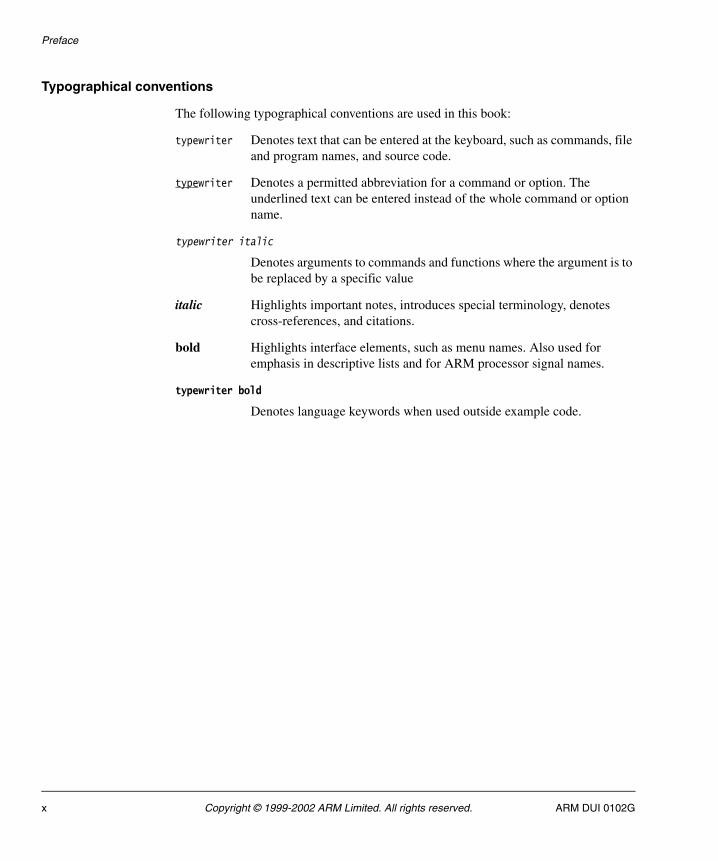
Typographical conventions
The following typographical conventions are used in this book:
typewriter Denotes text that can be entered at the keyboard, such as commands, file and program names, and source code.
typewriter Denotes a permitted abbreviation for a command or option. The underlined text can be entered instead of the whole command or option name.
typewriter italic
Denotes arguments to commands and functions where the argument is to be replaced by a specific value
italic Highlights important notes, introduces special terminology, denotes cross-references, and citations.
bold Highlights interface elements, such as menu names. Also used for emphasis in descriptive lists and for ARM processor signal names.
typewriter bold
Denotes language keywords when used outside example code.
x Copyright © 1999-2002 ARM Limited. All rights reserved. ARM DUI 0102G

Preface
Further reading
This section lists publications from ARM and third parties that provide additional information about developing on ARM processors.
ARM publications
The following publication provides a simplified guide to running the demonstration applications:
• ARM Firmware Suite User Guide (ARM DUI 0136).
The following publications provide information about ARM Integrator products:
• ARM Integrator/CM920T User Guide (ARM DDI 0097)
• ARM Integrator/CM940T User Guide (ARM DDI 0125)
• ARM Integrator/CM720T User Guide (ARM DDI 0126)
• ARM Integrator/CM740T User Guide (ARM DDI 0124)
• ARM Integrator/CM7TDMI User Guide (ARM DDI 0126)
• ARM Integrator/SP User Guide (ARM DUI 0099)
• ARM Integrator/AP User Guide (ARM DUI 0098).
The following publication provides information about ARM Prospector products:
• ARM Prospector/P1100 User Guide (ARM DUI 122).
The following publications provide information about ARM hardware and software debugging tools:
• ARM RMHost User Guide (ARM DUI 0137)
• ARM RMTarget Integration Guide (ARM DUI 0142)
• Multi-ICE User Guide (ARM DUI 0048).
The following publication provides reference information about ARM architecture:
• AMBA Specification (ARM IHI 0011).
ARM DUI 0102G Copyright © 1999-2002 ARM Limited. All rights reserved. xi
Preface
The following publications provide information about the ARM Developer Suite:
• ADS Getting Started (ARM DUI 0064)
• ADS Tools Guide (ARM DUI 0067)
• ADS Debuggers Guide (ARM DUI 0066)
• ADS Debug Target Guide (ARM DUI 0058)
• ADS Developer Guide (ARM DUI 0056)
• ADS CodeWarrior IDE Guide (ARM DUI 0065).
Further information can be obtained from the ARM web site at:
http://www.arm.com
Other publications
The following publication provides reference information about ARM architecture:
• ARM Architecture Reference, David Seal, Addison Wesley, ISBN 0-201-73719-1
• ARM System-On-Chip Architecture, Steve Furber, Addison Wesley, ISBN 0-201-67519-6.
The following publications provide information and guidelines for developing products for Microsoft Windows CE:
• HARP Enclosure Requirements for Microsoft® Windows® CE 1998 Microsoft Corporation
• Standard Development Board for Microsoft® Windows® CE 1998 Microsoft Corporation.
Further information on Microsoft Windows CE is available from the Microsoft web site:
http://www.microsoft.com
The following publication provides information about µC/OS-II:
• MicroC/OS-II, The Real-Time Kernel, Jean Labrosse, R&D Technical Books, ISBN 0-87930-543-6.
xii Copyright © 1999-2002 ARM Limited. All rights reserved. ARM DUI 0102G
Preface
Feedback
Feedback on both AFS and the documentation is welcome.
Feedback on this book
If you have any comments on this book, please send email to [email protected] giving:
• the document title
• the document number
• the page number(s) to which your comments apply
• a concise explanation of your comments.
General suggestions for additions and improvements are also welcome.
Feedback on the ARM Firmware Suite
If you have any problems with the ARM Firmware Suite, please contact your supplier. To help them provide a rapid and useful response, please give:
• details of the release you are using
• details of the platform you are running on, such as the hardware platform, operating system type and version
• a small standalone sample of code that reproduces the problem
• a clear explanation of what you expected to happen, and what actually happened
• the commands you used, including any command-line options
• sample output illustrating the problem
• the version string of the tool used, including the version number and date.
ARM DUI 0102G Copyright © 1999-2002 ARM Limited. All rights reserved. xiii

Preface
xiv Copyright © 1999-2002 ARM Limited. All rights reserved. ARM DUI 0102G
Chapter 1 Introduction to the ARM Firmware Suite
This chapter introduces the AFS components and utilities used to develop applications and operating systems on ARM-based systems. It contains the following sections:
• About the ARM Firmware Suite on page 1-2
• AFS directories and files on page 1-3.
Refer to the ARM Firmware Suite User Guide for a more detailed introduction to AFS.
ARM DUI 0102G Copyright © 1999-2002 ARM Limited. All rights reserved. 1-1
Introduction to the ARM Firmware Suite
1.1 About the ARM Firmware Suite
AFS provides:
µHAL libraries
µHAL (pronounced Micro-HAL) is the ARM Hardware Abstraction Layer that is the basis of the AFS. µHAL is a set of low-level functions that simplify the porting of operating systems and applications.
Flash library
The flash library provides an API for programming and reading flash memory. The API provides access to individual blocks or words in flash, and access to images and user data.
Development environment
AFS is an easy-to-use environment for evaluating ARM-based platforms. The library APIs enable rapid development of applications and device drivers. Reusable code is provided to help develop applications and product architectures on a wide range of ARM and third-party development platforms.
AFS is compatible with the ARM Development Suite (ADS 1.0 or higher). It supports the Angel debug monitor, Multi-ICE (if the target board supports it), and third-party debug monitors.
Additional components
Additional components provided with AFS include a boot monitor, generic applications, and board-specific applications. Use these components to verify that your development board is working correctly. You can use the source code for the applications as a starting point for your own applications.
Additional libraries
AFS supplies libraries for specialized hardware. For example, the supplied PCI library supports the PCI bus on the Integrator board.
Angel A version of Angel that has been implemented using µHAL is included with AFS.
µC/OS-II AFS includes a port of µC/OS-II for the ARM architecture using the µHAL interfaces.
1-2 Copyright © 1999-2002 ARM Limited. All rights reserved. ARM DUI 0102G
Introduction to the ARM Firmware Suite
1.2 AFS directories and files
This section describes the directories created by the AFS installer. Throughout this book there are examples of source code provided as part of AFS. The path names used assume that you installed AFS in the default directory AFSv1_4.
1.2.1 AFS installation layout
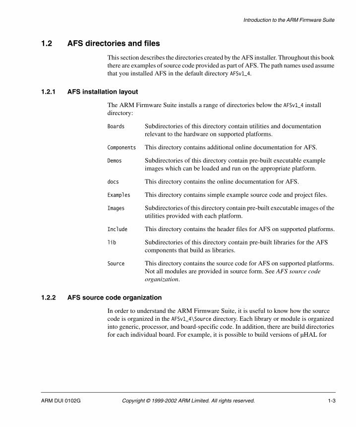
The ARM Firmware Suite installs a range of directories below the AFSv1_4 install directory:
Boards Subdirectories of this directory contain utilities and documentation relevant to the hardware on supported platforms.
Components This directory contains additional online documentation for AFS.
Demos Subdirectories of this directory contain pre-built executable example images which can be loaded and run on the appropriate platform.
docs This directory contains the online documentation for AFS.
Examples This directory contains simple example source code and project files.
Images Subdirectories of this directory contain pre-built executable images of the utilities provided with each platform.
Include This directory contains the header files for AFS on supported platforms.
lib Subdirectories of this directory contain pre-built libraries for the AFS components that build as libraries.
Source This directory contains the source code for AFS on supported platforms. Not all modules are provided in source form. See AFS source code organization.
1.2.2 AFS source code organization
In order to understand the ARM Firmware Suite, it is useful to know how the source code is organized in the AFSv1_4\Source directory. Each library or module is organized into generic, processor, and board-specific code. In addition, there are build directories for each individual board. For example, it is possible to build versions of µHAL for
ARM DUI 0102G Copyright © 1999-2002 ARM Limited. All rights reserved. 1-3
Introduction to the ARM Firmware Suite
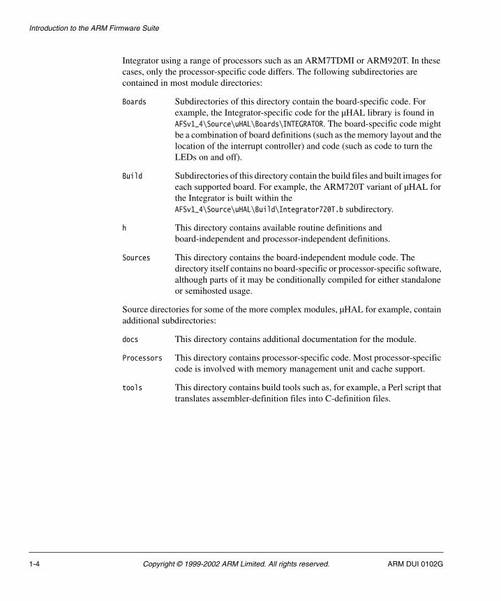
Integrator using a range of processors such as an ARM7TDMI or ARM920T. In these cases, only the processor-specific code differs. The following subdirectories are contained in most module directories:
Boards Subdirectories of this directory contain the board-specific code. For example, the Integrator-specific code for the µHAL library is found in AFSv1_4\Source\uHAL\Boards\INTEGRATOR. The board-specific code might be a combination of board definitions (such as the memory layout and the location of the interrupt controller) and code (such as code to turn the LEDs on and off).
Build Subdirectories of this directory contain the build files and built images for each supported board. For example, the ARM720T variant of µHAL for the Integrator is built within the AFSv1_4\Source\uHAL\Build\Integrator720T.b subdirectory.
h This directory contains available routine definitions and board-independent and processor-independent definitions.
Sources This directory contains the board-independent module code. The directory itself contains no board-specific or processor-specific software, although parts of it may be conditionally compiled for either standalone or semihosted usage.
Source directories for some of the more complex modules, µHAL for example, contain additional subdirectories:
docs This directory contains additional documentation for the module.
Processors This directory contains processor-specific code. Most processor-specific code is involved with memory management unit and cache support.
tools This directory contains build tools such as, for example, a Perl script that translates assembler-definition files into C-definition files.
1-4 Copyright © 1999-2002 ARM Limited. All rights reserved. ARM DUI 0102G
Chapter 2 µHAL Application Programming Interfaces
This chapter describes the simple and extended APIs to µHAL. It contains the following sections:
• About the µHAL APIs on page 2-2
• Simple API memory functions on page 2-4
• Simple API interrupt functions on page 2-8
• Simple API MMU and cache functions on page 2-11
• Simple API timer functions on page 2-13
• Simple API support functions on page 2-19
• Simple API LED control functions on page 2-21
• Serial input/output functions, definitions, and macros on page 2-25
• Extended API initialization functions on page 2-31
• Extended API interrupt handling functions on page 2-33
• Extended API software interrupt (SWI) function on page 2-38
• Extended API MMU and cache functions on page 2-39
• Extended API processor execution mode functions on page 2-43
• Extended API timer functions on page 2-46
• Extended API coprocessor access functions on page 2-49
• Library support functions on page 2-51.
ARM DUI 0102G Copyright © 1999-2002 ARM Limited. All rights reserved. 2-1

µHAL Application Programming Interfaces
2.1 About the µHAL APIs
This section provides an overview of the general APIs provided by µHAL. See µHAL PCI function descriptions on page 8-17 for a description of PCI functions contained in µHAL.
2.1.1 µHAL-specific function types
µHAL uses three function types that are abstracted to make interface routines easier to use. These are described in Table 2-1.
For example, with the uHALr_RequestTimer() declaration:
int uHALr_RequestTimer(PrHandler handler, const unsigned char *devname)
an interrupt handler can be declared as:
void TickTimer(unsigned int interrupt)
and registered with µHAL using:
uHALr_RequestSystemTimer(TickTimer, "test");
Table 2-1 Parameter types
Description Syntax
A pointer to a function with no argument. The function does not return a value.
typedef void (*PrVoid)(void);
A pointer to a function with one integer argument. The function does not return a value.
typedef void (*PrHandler)(unsigned int);
A pointer to a function with no argument. The function returns a PrVoid pointer to a function.
typedef PrVoid (*PrPrVoid)(void);
2-2 Copyright © 1999-2002 ARM Limited. All rights reserved. ARM DUI 0102G
µHAL Application Programming Interfaces
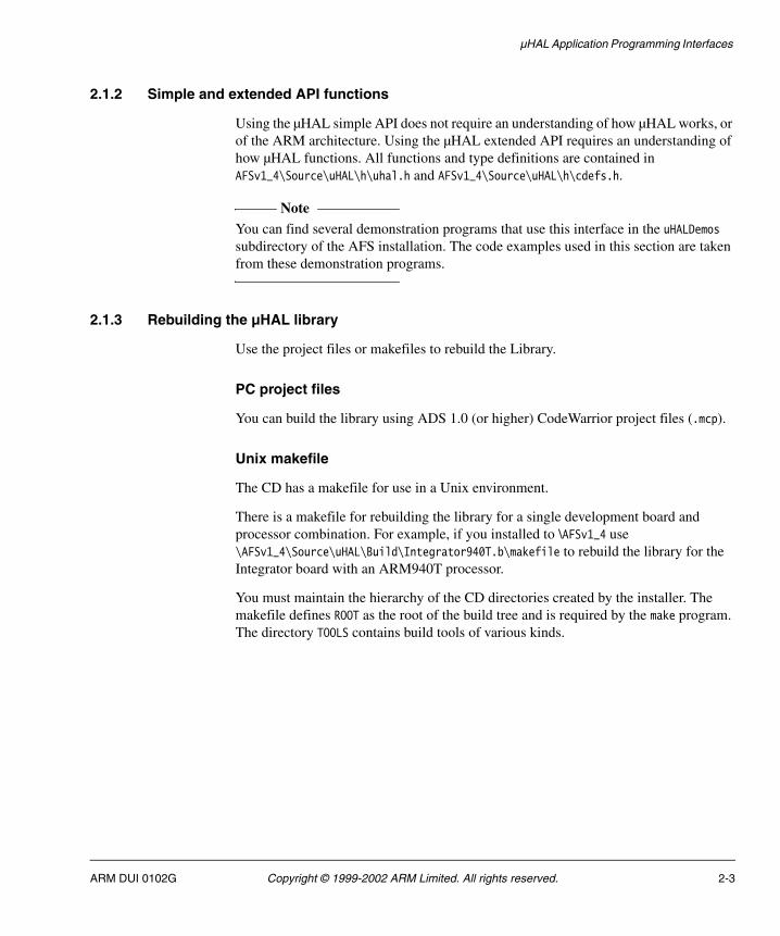
2.1.2 Simple and extended API functions
Using the µHAL simple API does not require an understanding of how µHAL works, or of the ARM architecture. Using the µHAL extended API requires an understanding of how µHAL functions. All functions and type definitions are contained in AFSv1_4\Source\uHAL\h\uhal.h and AFSv1_4\Source\uHAL\h\cdefs.h.
Note You can find several demonstration programs that use this interface in the uHALDemos subdirectory of the AFS installation. The code examples used in this section are taken from these demonstration programs.
2.1.3 Rebuilding the µHAL library
Use the project files or makefiles to rebuild the Library.
PC project files
You can build the library using ADS 1.0 (or higher) CodeWarrior project files (.mcp).
Unix makefile
The CD has a makefile for use in a Unix environment.
There is a makefile for rebuilding the library for a single development board and processor combination. For example, if you installed to \AFSv1_4 use \AFSv1_4\Source\uHAL\Build\Integrator940T.b\makefile to rebuild the library for the Integrator board with an ARM940T processor.
You must maintain the hierarchy of the CD directories created by the installer. The makefile defines ROOT as the root of the build tree and is required by the make program. The directory TOOLS contains build tools of various kinds.
ARM DUI 0102G Copyright © 1999-2002 ARM Limited. All rights reserved. 2-3

µHAL Application Programming Interfaces
2.2 Simple API memory functions
This section describes the set of functions that are used to find free memory in the system, and to allocate and free heap storage. Free memory is memory that is not used by µHAL itself or a debug agent. Prototypes for all of these functions are available in AFSv1_4\Source\uHAL\h\uhal.h.
The memory functions are:
• uHALr_StartOfRam()
• uHALr_EndOfFreeRam()
• uHALr_EndOfRam() on page 2-5
• uHALr_HeapAvailable() on page 2-5
• uHALr_InitHeap() on page 2-5
• uHALr_malloc() on page 2-5
• uHALr_free() on page 2-6.
There is an example of a program that allocates and de-allocates heap storage in Example of heap allocation and de-allocation on page 2-7.
2.2.1 uHALr_StartOfRam()
This function returns the address of the first free uninitialized RAM location.
Syntax
void *uHALr_StartOfRam(void)
Return value
Returns the address of the first available RAM location.
2.2.2 uHALr_EndOfFreeRam()
This function returns the address of the last available RAM location.
Syntax
void *uHALr_EndOfFreeRam(void)
Return value
Returns the address of the last available RAM location.
2-4 Copyright © 1999-2002 ARM Limited. All rights reserved. ARM DUI 0102G

µHAL Application Programming Interfaces
2.2.3 uHALr_EndOfRam()
This function returns the address of the last RAM location.
Syntax
void *uHALr_EndOfRam(void)
Return value
Returns the address of last RAM location.
2.2.4 uHALr_HeapAvailable()
This function returns a flag to indicate whether this port of the µHAL library includes support for heap management.
Syntax
int uHALr_HeapAvailable(void)
Return value
Returns one of the following:
1 If the heap management functions are included in the library.
0 If heap management functions are not included.
2.2.5 uHALr_InitHeap()
This function initializes the heap. It must be called before any memory allocation or de-allocation is attempted.
Syntax
void uHALr_InitHeap(void)
2.2.6 uHALr_malloc()
This function allocates contiguous storage from the heap.
Syntax
void *uHALr_malloc(unsigned int size)
ARM DUI 0102G Copyright © 1999-2002 ARM Limited. All rights reserved. 2-5
µHAL Application Programming Interfaces
where:
size is the number of bytes of memory required.
Return value
Returns
0 If size is 0.
-1 If the memory cannot be allocated.
pointer If successful, a pointer to the allocated memory is returned.
2.2.7 uHALr_free()
This routine frees previously allocated memory pointed at by memPtr.
Syntax
void uHALr_free(void *memPtr)
where:
memPtr Is a pointer to the heap memory to be freed. This value must not be –1. If the value is 0, the function returns without taking any action.
2-6 Copyright © 1999-2002 ARM Limited. All rights reserved. ARM DUI 0102G

µHAL Application Programming Interfaces
2.2.8 Example of heap allocation and de-allocation
Example 2-1 shows an example of a program that allocates and de-allocates heap storage. You can find a similar program in uHALDemos\Sources\heap.c.
Example 2-1 Allocating and de-allocating heap storage
#include "uhal.h"int main (int argc, int *argv[])
{ int i ;
void *memP ;uHALr_printf("*** HEAP Allocation/Deallocation ***\n") ;uHALr_InitHeap() ; // initfor (i = 0 ; i < 16 ; i++) { // allocate and free some memory
uHALr_printf("malloc'ing 0x%X bytes...", i * 16) ; memP = uHALr_malloc(i * 16) ;uHALr_printf("@ 0x%X\n", memP) ;
uHALr_free(memP) ; } return (OK);}
ARM DUI 0102G Copyright © 1999-2002 ARM Limited. All rights reserved. 2-7

µHAL Application Programming Interfaces
2.3 Simple API interrupt functions
µHAL assumes that interrupts occur using IRQs. These routines allow you to:
• install a generic interrupt handler
• request control of a particular interrupt
• enable and disable that interrupt.
Your application can install different interrupt handlers for different interrupts, or install a single handler for many interrupts.
When an interrupt occurs, µHAL traps it and calls the appropriate handler routine, passing it the number of the interrupt that occurred.
Note µHAL does not provide any support to the application for finding the source of interrupts. It is the responsibility of the board-specific code to map the programmable interrupt controller format to and from a 32-bit quantity.
The interrupt functions are:
• uHALr_InitInterrupts()
• uHALr_RequestInterrupt() on page 2-9
• uHALr_FreeInterrupt() on page 2-9
• uHALr_EnableInterrupt() on page 2-10
• uHALr_DisableInterrupt() on page 2-10.
2.3.1 uHALr_InitInterrupts()
This function is called once on startup by the application. It initializes the µHAL internal interrupt structures. This must be called before installing a new IRQ handler.
Syntax
void uHALr_InitInterrupts(void)
2-8 Copyright © 1999-2002 ARM Limited. All rights reserved. ARM DUI 0102G

µHAL Application Programming Interfaces
2.3.2 uHALr_RequestInterrupt()
This function assigns a high-level handler routine to the specified interrupt. It sets up the internal structures, but does not activate the interrupt.
Syntax
int uHALr_RequestInterrupt(unsigned int intNum, PrHandler handler, const unsigned char *devname)
where:
intNum Is the number of the interrupt to be processed.
handler Is a pointer to the routine that processes the interrupt.
devname Is a pointer to a string identifying the function of the interrupt.
Return value
Returns one of the following:
0 If successful.
-1 If intNum is unknown or already assigned.
2.3.3 uHALr_FreeInterrupt()
This function removes the high-level handler from the specified interrupt.
Note An application must always call uHALr_DisableInterrupt() before calling this routine. Call uHALr_FreeInterrupt() before changing the routine associated with an interrupt.
Syntax
int uHALr_FreeInterrupt(unsigned int intNum)
where:
intNum Is the number of the interrupt to be freed.
Return value
Returns one of the following:
0 If successful.
-1 If intNum is unknown, reserved, or not allocated.
ARM DUI 0102G Copyright © 1999-2002 ARM Limited. All rights reserved. 2-9
µHAL Application Programming Interfaces
2.3.4 uHALr_EnableInterrupt()
This function enables the specified interrupt. On many ARM-based systems, this is a two-step process. It enables an on-board interrupt controller, and then it enables the interrupt mask on the processor.
Syntax
void uHALr_EnableInterrupt(unsigned int intNum)
where:
intNum Is the number of the interrupt to be enabled.
2.3.5 uHALr_DisableInterrupt()
This function disables the specified interrupt. On many ARM-based systems, interrupts are enabled and disabled at two stages:
• an on-board controller
• the interrupt mask on the processor.
The uHALr_DisableInterrupt() function disables the interrupt on the interrupt controller and does not affect masking by the processor.
Syntax
void uHALr_DisableInterrupt(unsigned int intNum)
where:
intNum Is the number of the interrupt to be disabled. The routine has no effect if the number is not in the range of valid interrupts.
2-10 Copyright © 1999-2002 ARM Limited. All rights reserved. ARM DUI 0102G
µHAL Application Programming Interfaces
2.4 Simple API MMU and cache functions
On processors that support it, µHAL allows an application to:
• Turn virtual memory on and off using the Memory Management Unit (MMU). (On systems that use the MMU to remap read-only memory at address 0, the MMU cannot be disabled.)
• Enable and disable the caches.
These functions are:
• uHALr_ResetMMU()
• uHALr_InitMMU()
• uHALr_EnableCache() on page 2-12
• uHALr_DisableCache() on page 2-12.
Memory management and cache code example on page 2-12 includes an example of a basic cache manipulation program.
2.4.1 uHALr_ResetMMU()
This function safely resets the MMU (and caches) to a fully disabled state (all OFF), irrespective of the state they were originally in. If the MMU cannot be disabled, this function has no effect.
Syntax
void uHALr_ResetMMU(void)
2.4.2 uHALr_InitMMU()
This function initializes the MMU to a default one-to-one mapping. This mapping also defines the types of access allowed to each area according to execution mode. For example, flash can be written in Supervisor mode, but not User mode.
Syntax
void uHALr_InitMMU(int mode)
where:
mode Is any combination of the MMU mode flags and cache bit flags, EnableMMU, IC_ON, DC_ON, and WB_ON. See also uHALir_WriteCacheMode() on page 2-42.
ARM DUI 0102G Copyright © 1999-2002 ARM Limited. All rights reserved. 2-11

µHAL Application Programming Interfaces
2.4.3 uHALr_EnableCache()
This function provides a way to enable all caches that are supported by the processor.
Syntax
void uHALr_EnableCache(void)
2.4.4 uHALr_DisableCache()
This function disables all caches that are supported by the processor.
Syntax
void uHALr_DisableCache(void)
2.4.5 Memory management and cache code example
Example 2-2 is an example of a simple cache manipulation program. A similar program is in uHALDemos\Sources\simple-caches.c.
Example 2-2 MMU and cache
#include "uhal.h" #include "mmu_h.h" int main (int argc, int *argv[]) {
uHALr_printf("Simple Cache Usage [v1.0]\n") ;// who are we? uHALr_printf("Resetting caches...") ; // Reset the caches to a known stateuHALr_ResetMMU() ;uHALr_printf("done\n") ;uHALr_printf("Enabling the MMU and all caches...") ;// Init MMU to all on uHALr_InitMMU(IC_ON | DC_ON | WB_ON | EnableMMU) ; uHALr_printf("done\n") ;uHALr_printf("Disabling all caches...") ; // Disable the caches uHALr_DisableCache() ;uHALr_printf("done\n") ;
// Finally, enable all of the cachesuHALr_printf("Enabling all caches...") ; uHALr_EnableCache() ; uHALr_printf("done\n") ; return (OK);// go home
}
2-12 Copyright © 1999-2002 ARM Limited. All rights reserved. ARM DUI 0102G

µHAL Application Programming Interfaces
2.5 Simple API timer functions
µHAL provides a set of routines that allow an application to use a timer as a system or operating system timer. This is the simplest way to use timers in µHAL.
µHAL also provides generic timer access routines that give more direct access, although with a little more complexity, to the timers in the system.
The timer functions are:
• uHALr_CountTimers()
• uHALr_InitTimers()
• uHALr_RequestSystemTimer() on page 2-14
• uHALr_InstallSystemTimer() on page 2-14
• uHALr_RequestTimer() on page 2-15
• uHALr_InstallTimer() on page 2-16
• uHALr_FreeTimer() on page 2-16
• uHALr_GetTimerInterval() on page 2-16
• uHALr_SetTimerInterval() on page 2-17
• uHALr_GetTimerState() on page 2-17
• uHALr_SetTimerState() on page 2-18
• uHALr_EnableTimer() on page 2-18
• uHALir_GetSystemTimer() on page 2-48.
System timer programming example on page 2-15 shows how to use a system timer.
2.5.1 uHALr_CountTimers()
This function returns the number of timers that are supported by the target.
Syntax
unsigned int uHALr_CountTimers(void)
Return value
Returns the number of timers supported by the target.
2.5.2 uHALr_InitTimers()
This function must be called before any other timer function. This function:
• Initializes the µHAL internal interrupt structures.
ARM DUI 0102G Copyright © 1999-2002 ARM Limited. All rights reserved. 2-13

µHAL Application Programming Interfaces
• Resets all timers to a known state. (It sets the internal delays to a predefined value and sets all timers off.)
If this function is compiled for use with a debug agent, such as Angel, the timer associated with the debug agent is not reset and is locked to prevent access from within µHAL.
Note For the timer interrupt handler to be correctly installed, the application must ensure that uHALr_InitInterrupts() has been called before this function call.
Syntax
void uHALr_InitTimers(void)
2.5.3 uHALr_RequestSystemTimer()
This function installs a handler for the system timer, sets up the internal structures, and stops (and does not restart) the timer. By default, the system timer is set to tick once every millisecond.
Syntax
int uHALr_RequestSystemTimer(PrHandler handler, const unsigned char *devname)
where:
handler Is a pointer to the routine that will process the interrupt.
devname Is a pointer to a string identifying the function of the interrupt.
Return value
Returns one of the following:
0 If successful.
-1 If the IRQ is already assigned.
2.5.4 uHALr_InstallSystemTimer()
This function starts the timer and enables the interrupt associated with it.
Syntax
void uHALr_InstallSystemTimer(void)
2-14 Copyright © 1999-2002 ARM Limited. All rights reserved. ARM DUI 0102G

µHAL Application Programming Interfaces
2.5.5 System timer programming example
The program in Example 2-3 demonstrates how a system timer is used.
Example 2-3 System timer example
#include "uhal.h"// High-level routine called by IRQ Trap Handler when the timer interruptsstatic int OSTick = 0 ;void TickTimer(unsigned int irq){
OSTick++ ;}
int main (int argc, int *argv[]) {int i, j ;
uHALr_printf("System Timer\n") ; // who are we? uHALr_InitInterrupts() ; // Install new trap handlers and soft vectorsuHALr_InitTimers() ; // initialize the timersOSTick = 0 ; // initialize the tick countuHALr_printf("Timer init\n") ;if (uHALr_RequestSystemTimer(TickTimer,(const unsigned char*)"test")<= 0)
uHALr_printf("Timer/IRQ busy\n") ;
// Start system timer & enable the interruptuHALr_InstallSystemTimer() ; // loop flashing a led and giving out the tick count for (j = 0; ; j++) {
if (j & 1) uHALr_SetLED(1) ;
elseuHALr_ResetLED(1) ;
uHALr_printf("Tick is %x\n", OSTick) ; for (i = 0 ; i < 1000000 ; i++) ;
}return (OK);
}
2.5.6 uHALr_RequestTimer()
This function gets the next available timer and installs a handler. On return, the timer is initialized but not running.
Syntax
int uHALr_RequestTimer(PrHandler handler, const unsigned char *devname)
ARM DUI 0102G Copyright © 1999-2002 ARM Limited. All rights reserved. 2-15

µHAL Application Programming Interfaces
where:
handler Is a pointer to the routine that will process the interrupt.
devname Is a pointer to a string identifying the function of the interrupt.
Return value
Returns one of the following:
timer If successful, the timer number is returned.
-1 If the timer is unknown or already assigned.
2.5.7 uHALr_InstallTimer()
This function starts the specified timer by enabling the timer and the associated interrupt.
void uHALr_InstallTimer(unsigned int timer)
where:
timer Is the timer to be started.
2.5.8 uHALr_FreeTimer()
This function disables the specified timer, frees the interrupt, and updates the internal structure.
Syntax
int uHALr_FreeTimer(unsigned int timer)
where:
timer Is the number of the timer to be freed.
Return value
Returns one of the following:
0 If successful.
-1 If the timer is unknown.
2.5.9 uHALr_GetTimerInterval()
This function gets the interval, in microseconds, for the specified timer.
2-16 Copyright © 1999-2002 ARM Limited. All rights reserved. ARM DUI 0102G
µHAL Application Programming Interfaces
Syntax
int uHALr_GetTimerInterval(unsigned int timer)
where:
timer Is the number of the timer for which the interval is requested.
Return value
Returns one of the following:
interval If successful (return value in microseconds).
-1 If the timer is not found.
2.5.10 uHALr_SetTimerInterval()
This function sets the interval, in microseconds, for the specified timer.
Syntax
int uHALr_SetTimerInterval(unsigned int timer, unsigned int interval)
where:
timer Is the timer number for which the interval is to be set.
interval Is the number of microseconds between events.
Return value
Returns one of the following:
0 If the timer is found.
-1 If the timer is not found.
2.5.11 uHALr_GetTimerState()
This function gets the current state of the specified timer.
Syntax
int uHALr_GetTimerState(unsigned int timer)
where:
timer Is the timer number for which the state is requested.
ARM DUI 0102G Copyright © 1999-2002 ARM Limited. All rights reserved. 2-17

µHAL Application Programming Interfaces
Return value
Returns one of the following:
state If the timer is found, the current state is one of:
T_FREE Available.
T_ONESHOT Single-shot timer (in use).
T_INTERVAL Repeating timer (in use).
T_LOCKED Not available for use by µHAL.
-1 If the timer is not found.
2.5.12 uHALr_SetTimerState()
This function sets the timer state.
Syntax
int uHALr_SetTimerState(unsigned int timer, enum uHALe_TimerState state)
where:
timer Is the timer number for which the state is being set.
state Is a valid timer state which is one of:
T_ONESHOT Single-shot timer (in use).
T_INTERVAL Repeating timer (in use).
Return value
Returns one of the following:
0 If the timer is found.
-1 If the timer is not found.
2.5.13 uHALr_EnableTimer()
This function reloads the interval and enables the specified timer.
Syntax
void uHALr_EnableTimer(unsigned int timer)
where:
timer Is the timer to be enabled.
2-18 Copyright © 1999-2002 ARM Limited. All rights reserved. ARM DUI 0102G

µHAL Application Programming Interfaces
2.6 Simple API support functions
In addition to the general routines, µHAL provides implementations of a number of standard C library routines. The support functions include:
• uHALr_memset()
• uHALr_memcmp()
• uHALr_memcpy() on page 2-20
• uHALr_strlen() on page 2-20.
2.6.1 uHALr_memset()
This function places character c into the first n characters of s, and returns s.
Syntax
void *uHALr_memset(char *s, int c, int n)
where:
s Is the start address of memory to be set.
c Is the character to be copied into memory.
n Is the number of memory locations to be used.
Return value
Returns s.
2.6.2 uHALr_memcmp()
This function compares the first n characters of cs with ct.
Syntax
int uHALr_memcmp(char *cs, char *ct, int n)
where:
cs Is the start of memory locations to be compared.
ct Is the start of memory locations to be compared against.
n Is the number of memory locations to be compared.
ARM DUI 0102G Copyright © 1999-2002 ARM Limited. All rights reserved. 2-19
µHAL Application Programming Interfaces
Return value
Returns one of the following:
1 If cs>ct.
0 If cs=ct.
-1 If cs<ct.
2.6.3 uHALr_memcpy()
This function copies n characters from ct to s.
Syntax
void * uHALr_memcpy(char *s, char *ct, int n)
where:
s Is a pointer to the destination memory locations.
ct Is a pointer to the source memory locations.
n Is the number of memory locations to be copied.
Return value
Returns the address of the first location copied to.
2.6.4 uHALr_strlen()
This function returns the length of s.
Syntax
int uHALr_strlen(const char *s)
where:
s Is a pointer to a zero-terminated string.
Return value
This function returns the size, in bytes, of s.
2-20 Copyright © 1999-2002 ARM Limited. All rights reserved. ARM DUI 0102G
µHAL Application Programming Interfaces
2.7 Simple API LED control functions
µHAL provides a set of simple routines for accessing any LEDs in the system. The LED control functions are:
• uHALr_CountLEDs() on page 2-22
• uHALr_InitLEDs() on page 2-22
• uHALr_ResetLED() on page 2-22
• uHALr_SetLED() on page 2-23
• uHALr_ReadLED() on page 2-23
• uHALr_WriteLED() on page 2-23.
An example of a simple LED flashing program is provided in LED control code example on page 2-24.
2.7.1 LED states and addresses
The µHAL LED code is generic and manages any LEDs that can be accessed at different addresses on different boards. Logic 1 can indicate either ON or OFF.
The LED code in the module AFSv1_4\Source\uHAL\Sources\led.c keeps the LED addresses (or homes) in the uHALiv_LedHomes array.
The set of pointers to LEDs is initialized to be the contents of uHAL_LED_OFFSETS. The addresses, pointers, and the number of LEDs (uHAL_NUM_OF_LEDS), are defined in the board-specific definition files platform.s and platform.h. The platform definitions for the generic Integrator platform, for example, are in AFSv1_4\Source\uHAL\Boards\INTEGRATOR.
For some systems, the platform files contain different addresses for different LEDs. The LED code also keeps a set of masks, one per LED, in the uHALiv_LedMasks array. This is set to the contents of UHAL_LED_MASKS.
When reading the state of the LEDs, the LED code does the following:
1. Reads the LED register using its home address.
2. ANDs the value read with the mask for this LED.
3. Compares the result with the board-specific literal uHAL_LED_ON. Some LEDs report 0 as on.
A board-specific LED write function, uHALr_WriteLED() in board.c, is used to write to the LEDs.
ARM DUI 0102G Copyright © 1999-2002 ARM Limited. All rights reserved. 2-21

µHAL Application Programming Interfaces
2.7.2 uHALr_CountLEDs()
This function returns the number of LEDs available to the µHAL application.
Syntax
unsigned int uHALr_CountLEDs(void)
Return value
Returns the number of LEDs:
0 If there are no LEDs.
count If there are LEDs.
2.7.3 uHALr_InitLEDs()
This function initializes the LEDs in the system to OFF.
Syntax
unsigned int uHALr_InitLEDs(void)
Return value
Returns the number of LEDs.
2.7.4 uHALr_ResetLED()
This function turns the specified LED off.
Syntax
void uHALr_ResetLED(unsigned int led)
where:
led Is the specified LED number.
2-22 Copyright © 1999-2002 ARM Limited. All rights reserved. ARM DUI 0102G

µHAL Application Programming Interfaces
2.7.5 uHALr_SetLED()
This function turns the specified LED on.
Syntax
void uHALr_SetLED(unsigned int led)
where:
led Is the specified LED number.
2.7.6 uHALr_ReadLED()
This function returns the state of the specified LED.
Syntax
int uHALr_ReadLED(unsigned int led)
where:
led Is the specified LED number.
Return value
Returns one of the following:
TRUE If the LED state is on.
FALSE If the LED state is off.
-1 If the LED number specified is invalid.
TRUE is defined as 1 and FALSE is defined as 0.
2.7.7 uHALr_WriteLED()
This function writes a value to the specified LED.
Syntax
int uHALr_WriteLED(unsigned int led, unsigned int state)
ARM DUI 0102G Copyright © 1999-2002 ARM Limited. All rights reserved. 2-23
µHAL Application Programming Interfaces
where:
led Is the specified LED number.
state Is the desired LED state:
TRUE to turn the led on (1).
FALSE to turn the led off (0).
Return value
Returns one of the following:
0 If successful.
-1 If the LED number specified is invalid.
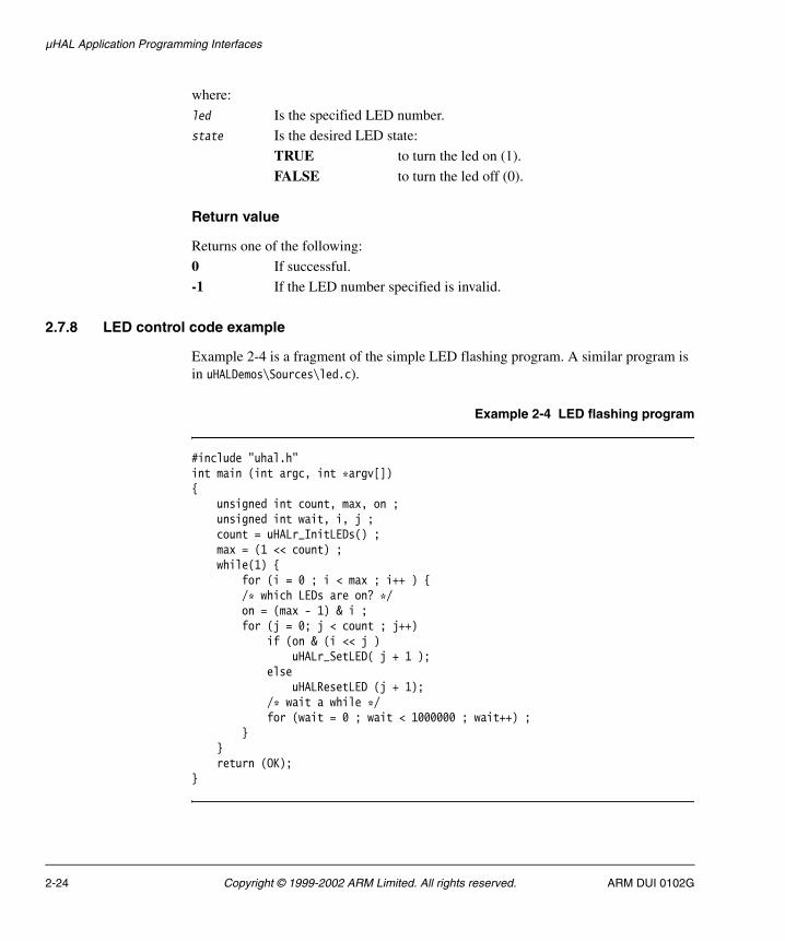
2.7.8 LED control code example
Example 2-4 is a fragment of the simple LED flashing program. A similar program is in uHALDemos\Sources\led.c).
Example 2-4 LED flashing program
#include "uhal.h"int main (int argc, int *argv[]){
unsigned int count, max, on ;unsigned int wait, i, j ;count = uHALr_InitLEDs() ;max = (1 << count) ;while(1) {
for (i = 0 ; i < max ; i++ ) {/* which LEDs are on? */on = (max - 1) & i ;for (j = 0; j < count ; j++)
if (on & (i << j )uHALr_SetLED( j + 1 );
elseuHALResetLED (j + 1);
/* wait a while */for (wait = 0 ; wait < 1000000 ; wait++) ;
}}return (OK);
}
2-24 Copyright © 1999-2002 ARM Limited. All rights reserved. ARM DUI 0102G

µHAL Application Programming Interfaces
2.8 Serial input/output functions, definitions, and macros
If there is a serial port, µHAL provides access for the application by using a series of polled calls. In the case of a semihosted application, µHAL makes SWI calls to the underlying debug agent to process the requests.
The simple serial I/O functions are:
• uHALr_ResetPort()
• uHALr_getchar()
• uHALr_putchar() on page 2-26
• uHALr_printf() on page 2-26.
A basic character I/O program example is provided in:
• Serial input/output code example on page 2-26.
The one extended serial function is:
• uHALir_InitSerial() on page 2-26.
2.8.1 uHALr_ResetPort()
This function resets the port defined for stdin/stdout to the board default state.
Syntax
void uHALr_ResetPort(void)
2.8.2 uHALr_getchar()
This function waits for a character from the default port. When compiled as a semihosted application, this function uses the SWI handler provided by the debug agent to get the character from the host console.
Syntax
unsigned int uHALr_getchar(void)
Return value
Returns the unsigned int containing the character read from the serial port.
ARM DUI 0102G Copyright © 1999-2002 ARM Limited. All rights reserved. 2-25

µHAL Application Programming Interfaces
2.8.3 uHALr_putchar()
This function sends the given character to the default port. When compiled as a semihosted application, this function uses the SWI handler provided by the debug agent to send the character to the host console.
Syntax
void uHALr_putchar(unsigned char c)
where:
c Is the character to be sent to the serial port.
2.8.4 uHALr_printf()
This function converts, formats, and writes the arguments to the standard output.
Syntax
void uHALr_printf(char *format, ...)
where:
format is a pointer to the start of the zero-terminated formatting string. You can insert any number of these parameters into the format string. The known format types are:
%i, %c, %s, %d, %u, %o, %x, and %X
... is a variable list of arguments to print.
2.8.5 uHALir_InitSerial()
This extended API function initializes the specified port to the specified baud rate.
Syntax
void uHALr_InitSerial(unsigned int port, unsigned int baudRate)
where:
port Is the base address of the serial port to be initialized.
baudRate Is the platform-specific value used to set the data transfer rate.
2.8.6 Serial input/output code example
Example 2-5 on page 2-27 shows a program performing simple character I/O.
2-26 Copyright © 1999-2002 ARM Limited. All rights reserved. ARM DUI 0102G

µHAL Application Programming Interfaces
Example 2-5 Simple character I/O
#include "uhal.h"extern void print_header(void);char * test_name = "Input/Output Tests\n";char * test_ver = "Program Version 1.0\n";extern void print_end (void);static int yesno(char *question, int preferred) { int c ; uHALr_printf(question) ; // ask the question if (preferred) uHALr_printf("[Yn]? ") ; else uHALr_printf("[Ny]? ") ; c = uHALr_getchar() ; // get the answer and interpret it uHALr_putchar(c) ; if (c == '\n') return preferred ; uHALr_putchar('\n') ; return ((c == 'y')||(c == 'Y')) ;}
int main (int argc, int *argv[]) { int i ; char buf[80] ; U8 c ; print_header(); // who are we? uHALr_printf("Please enter a string terminated by C/R\n") ; uHALr_printf("IO> ") ; // Ask for some characters (don't forget to echo) for (i = 0 ; i < sizeof(buf) ; i++) { c = uHALr_getchar() ; uHALr_putchar(c) ; if ((c == '\n') || (c == '\r')) { uHALr_putchar('\n') ; break ; } } // ask the user if they saw it correctly if (yesno("Were the characters echoed to screen properly", 1) == 1) uHALr_printf("Successful!\n") ; else uHALr_printf("Failed!\n") ; print_end (); return (OK);}
ARM DUI 0102G Copyright © 1999-2002 ARM Limited. All rights reserved. 2-27

µHAL Application Programming Interfaces
2.8.7 Serial input output board-specific definitions and macros
If µHAL is built to run as a semihosted application, all input and output is handled by the debug agent, for example Angel. In standalone mode, µHAL provides minimal serial input and output support, enough to reset the defined serial port and to handle polled input and output.
The board-specific definition files, platform.s and platform.h, describe the COM ports for a system and their usage. Example 2-6 shows the COM port definitions for an SA-1100 Prospector board.
Example 2-6 COM port definitions
#define HOST_COMPORT UART3_BASE /* define so that it only ever uses one port */ #define OS_COMPORT HOST_COMPORT /* Default port to talk to host via debugger */
where:
HOST_COMPORT Is the COM port used to communicate with a debug host using the Angel debug monitor.
OS_COMPORT Is the COM port used by an operating system or µHAL application.
On the Prospector board, these are defined to be the same so that a semihosted µHAL application uses semihosting for serial input and output. Because the Prospector board has two COM ports, you can use separate ports to prove that your application works using a real serial port. The board must supply a COM port-specific reset function, uHALir_InitSerial(). You can find this in the board-specific board.c module.
Note If you are using Multi-ICE with a semihosted application, the COM port is still reserved. Change the definition in platform.h to free the port.
2-28 Copyright © 1999-2002 ARM Limited. All rights reserved. ARM DUI 0102G
µHAL Application Programming Interfaces
The µHAL COM port input and output code uses several macros (defined in the board-specific definition files) to perform polled character input and output. The code is in the module AFSv1_4\Source\uHAL\Sources\iolib.c.
These macros are:
• GET_CHAR
• GET_STATUS
• RX_DATA
• TX_READY
• PUT_CHAR.
ARM DUI 0102G Copyright © 1999-2002 ARM Limited. All rights reserved. 2-29
µHAL Application Programming Interfaces
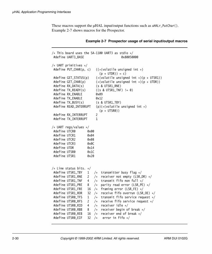
These macros support the µHAL input/output functions such as uHALr_PutChar(). Example 2-7 shows macros for the Prospector.
Example 2-7 Prospector usage of serial input/output macros
/* This board uses the SA-1100 UART3 as stdio */ #define UART3_BASE 0x80050000 /* UART primitives */ #define PUT_CHAR(p, c) ((*(volatile unsigned int *)
(p + UTDR)) = c) #define GET_STATUS(p) (*(volatile unsigned int *)(p + UTSR1)) #define GET_CHAR(p) (*(volatile unsigned int *)(p + UTDR)) #define RX_DATA(s) (s & UTSR1_RNE) #define TX_READY(s) ((s & UTSR1_TNF) != 0) #define RX_ENABLE 0x09 #define TX_ENABLE 0x12 #define TX_BUSY(s) (s & UTSR1_TBY) #define READ_INTERRUPT (p)(*(volatile unsigned int *)
(p + UTSR0)) #define RX_INTERRUPT 2 #define TX_INTERRUPT 1
/* UART regs/values */ #define UTCR0 0x00 #define UTCR1 0x04 #define UTCR2 0x08 #define UTCR3 0x0C #define UTDR 0x14 #define UTSR0 0x1C #define UTSR1 0x20
/* Line status bits. */ #define UTSR1_TBY 1 /* transmitter busy flag */ #define UTSR1_RNE 2 /* receiver not empty (LSR_DR) */ #define UTSR1_TNF 4 /* transmit fifo non full */ #define UTSR1_PRE 8 /* parity read error (LSR_PE) */ #define UTSR1_FRE 16 /* framing error (LSR_FE) */ #define UTSR1_ROR 32 /* receive fifo overrun (LSR_OE) */ #define UTSR0_TFS 1 /* transmit fifo service request */ #define UTSR0_RFS 2 /* receive fifo service request */ #define UTSR0_RID 4 /* receiver idle */ #define UTSR0_RBB 8 /* receiver begin of break */ #define UTSR0_REB 16 /* receiver end of break */ #define UTSR0_EIF 32 /* error in fifo */
2-30 Copyright © 1999-2002 ARM Limited. All rights reserved. ARM DUI 0102G
µHAL Application Programming Interfaces
2.9 Extended API initialization functions
The entry point to an ARM program is defined by either the -entry option of armlink or the assembler ENTRY directive. µHAL attaches this directive to the routine __main in AFSboot.s (This is a platform-specific file, so for Integrator it is AFSv1_4\Source\uHAL\Boards\INTEGRATOR\AFSboot.s). µHAL places the exception vectors at the start of the image so that the application functions correctly from RAM or ROM at address 0. When used in a system with static memory at address 0, the default vectors in AFSboot.s must be changed to correspond to the ones actually used in the high-level application.
All ARM processors execute their first instruction at address 0. In many systems, however, this address contains volatile RAM. Implementations that assert the HIVECS input pin to start CPU execution from an address other than 0 are not supported by µHAL. Each system must implement a mechanism to allow static memory, such as flash or ROM, to overlay this RAM so the program can start.
The startup procedure is:
1. Switch the memory map back to its normal layout by using the GOTO_ROM macro in the target specific target.s file.
2. Initialize the memory systems (if necessary) and determine the amount of RAM in the system.
3. If the application is compiled standalone, copy the exception vectors from static memory to RAM, starting at address 0.
4. Set up the stacks for the different processor modes and initialize the predefined data areas for the high-level application.
5. Initialize the rest of the system, including MMU, cache, serial ports, interrupts, and timers.
Some applications might hide this completely within the boot-up section. Others set up only the required functions from within the application.
The initialization functions are:
• uHALir_InitTargetMem() on page 2-32
• uHALir_InitBSSMemory() on page 2-32
• uHALir_PlatformInit() on page 2-32.
ARM DUI 0102G Copyright © 1999-2002 ARM Limited. All rights reserved. 2-31
µHAL Application Programming Interfaces
2.9.1 uHALir_InitTargetMem()
This function checks and initializes the memory system and then returns the address of the top of available memory. This function does not corrupt memory if it is already initialized.
Note This routine cannot be called from C because it assumes there is no stack and that registers do not have to be preserved.
Syntax
void *uHALir_InitTargetMem(void)
Return value
Returns Top of Memory +1 (in bytes) and stores it in uHALiv_TopOfMemory.
2.9.2 uHALir_InitBSSMemory()
This function is called from boot-up to initialize all memory used by C and any predefined assembler data areas. All predefined RAM data areas, except for MMU data tables, are initialized to zero.
Note This routine overwrites any variables declared within the application.
Syntax
void uHALir_InitBSSMemory(void)
2.9.3 uHALir_PlatformInit()
This function initializes any platform-specific systems that must be setup before control is passed to the application.
Syntax
void uHALir_PlatformInit(void)
2-32 Copyright © 1999-2002 ARM Limited. All rights reserved. ARM DUI 0102G

µHAL Application Programming Interfaces
2.10 Extended API interrupt handling functions
The ARM processor has IRQ and FIQ interrupts. µHAL avoids using FIQs, leaving them available to the debugger and/or user application.
How µHAL initializes interrupts depends on the mode you have built it to execute in:
• For standalone applications, the full set of vectors (contained in AFSboot.s) is usually copied to memory at physical address 0x00000000. AFSboot.s is a platform-specific file, so for Integrator it is AFSv1_4\Source\uHAL\Boards\INTEGRATOR\AFSboot.s)
• For semihosted applications, µHAL installs an interrupt handler when the application requests one. This vector contains the address of uHALir_IRQProcess(), a dummy IRQ handler.
When IRQs are installed (using uHALr_InitInterrupts()), µHAL installs a pointer to the default trap handling function uHALr_TrapIRQ() (in irqtrap.s) into the exception vector at offset 0x18.
When an interrupt occurs, uHALr_TrapIRQ() saves all the registers in an ATPCS-compliant manner and, optionally, calls several handler routines to actually handle the IRQ. These handlers are called:
• after the context has been saved on the IRQ stack
• after the source of the interrupt has been determined
• at the end of the interrupt, just before the PC is restored from lr.
These routine addresses are stored in uHALp_StartIRQ, uHALp_HandleIRQ, and uHALp_FinishIRQ, respectively. The interrupt exception vector is modified using uHALir_NewVector().
The interrupt handler functions are:
• uHALir_TrapIRQ() on page 2-34
• uHALir_NewVector() on page 2-34
• uHALir_NewIRQ() on page 2-35
• uHALir_DefineIRQ() on page 2-35
• uHALir_DispatchIRQ() on page 2-36
• uHALir_UnexpectedIRQ() on page 2-37.
ARM DUI 0102G Copyright © 1999-2002 ARM Limited. All rights reserved. 2-33

µHAL Application Programming Interfaces
2.10.1 uHALir_TrapIRQ()
This function:
1. Saves all the registers in an ATPCS-compliant manner.
2. Calls a StartIRQ() function, if defined.
3. Reads the interrupt mask and calls the high-level handler HandleIRQ().
4. Calls a FinishIRQ() function, if defined.
5. Jumps to a returned value as an address to finish IRQ processing, if FinishIRQ() returns this value.
You can specify your own handler to use instead of the default trap handler by directly calling this low-level interrupt installer (found in AFSv1_4\Source\uHAL\sources\irqlib.s). The application must completely handle its own interrupts. µHAL itself calls this routine from uHALr_InitIRQ() to install the low-level trap handler uHALr_TrapIRQ() and the high-level IRQ dispatcher uHALr_DispatchIRQ().
Note This function is intended as an IRQ handler and not a user-called function.
Syntax
void uHALir_TrapIRQ(void)
2.10.2 uHALir_NewVector()
This function replaces the specified exception vector with the given routine pointer.
Note This routine is not ATPCS-compliant as it can be called before stacks and memory are defined. The function must be called in Supervisor mode.
Syntax
int uHALir_NewVector(void *Vector, PrVoid LowLevel)
where:
Vector Is the address of the vector to be replaced.
LowLevel Is a pointer to the low-level exception handler.
2-34 Copyright © 1999-2002 ARM Limited. All rights reserved. ARM DUI 0102G

µHAL Application Programming Interfaces
Return values
The register contents on return are:
r0 The status:
• 0 if the new exception vector could not be written
• 1 if the old exception was an LDR PC instruction
• 2 otherwise.
r1 The address of the new vector, branch, or NULL.
r2 The address of the old vector, branch, or NULL.
2.10.3 uHALir_NewIRQ()
This function installs both the high-level and low-level IRQ routines. To install the low-level routine, its address is copied to the vector array used by the exception vectors.
Assuming that the application chooses to use the default trap handler, µHAL allows the application to specify handlers for the start and end of each interrupt, in addition to allowing it to actually handle the interrupt. For simple interrupts, only the IRQ handler is needed. However, some operating systems ported to µHAL make use of the start and finish handlers to aid context switching (typically done at the end of timer interrupt handling). Use this function to define any of these three interrupt handlers.
Syntax
PrVoid uHALir_NewIRQ(PrHandler HighLevel, PrVoid LowLevel)
where:
HighLevel is a pointer to the high-level routine that processes interrupts. By default, this is uHALr_DispatchIRQ().
LowLevel is a pointer to the low-level routine. This routine must switch out of IRQ mode and restore correct operation of the application upon completion. If this pointer is zero, the default routine uHALr_TrapIRQ() is installed.
Note If the function fails to install the routines, the return value is 0. A non-zero value indicates success.
2.10.4 uHALir_DefineIRQ()
This function allows some or all of the functionality of the low-level IRQ handler to be defined. If zero is passed as the pointer contents, no action is taken for that parameter.
ARM DUI 0102G Copyright © 1999-2002 ARM Limited. All rights reserved. 2-35

µHAL Application Programming Interfaces
This is the default interrupt dispatcher (found in AFSv1_4\Source\uHAL\Sources\irq.c). This is passed the interrupt sources as a 32-bit value. How the interrupt sources are determined is board-specific and the READ_INT macro in target.s is used for this purpose.
Syntax
void uHALir_DefineIRQ(PrVoid Start, PrPrVoid Finish, PrVoid Trap)
where:
Start Is a pointer to the routine to be executed at the start of every IRQ.
Finish Is a pointer to the routine to be executed at the finish of every IRQ.
Trap Is a pointer to a different low-level IRQ handler. This handler might function differently than the default operation. The default interrupt routine is uHALr_TrapIRQ().
Usage
Start and Finish are zero if not required, but if Trap is zero, the current vector is not overwritten. This routine must be called before the call to uHALr_InitInterrupt().
2.10.5 uHALir_DispatchIRQ()
This is the high-level interrupt handler that scans the IRQ flags to find the interrupt that caused the exception. The appropriate installed interrupt handler is then called. If no handler is found, a common unexpected IRQ routine is called.
The interrupts themselves are owned by an interrupt handler. The µHAL code in AFSv1_4\Source\uHAL\Sources\irq.c maintains the uHALv_IRQVector array of uHALis_IRQ structs that describe the handler for each interrupt source.
The format of the data structure is:
struct uHALis_IRQ {PrHandler handler ; /* Routine for */
/* specific interrupt */unsigned int flags ;unsigned int mask ;const unsigned char *name ; /* Debug, owner id */ struct uHALis_IRQ *next ; /* Useful for shared */
/* interrupts */};
2-36 Copyright © 1999-2002 ARM Limited. All rights reserved. ARM DUI 0102G
µHAL Application Programming Interfaces
There are NR_IRQS elements. NR_IRQS is defined in the board-specific platform.s and platform.h files. µHAL applications install interrupt handlers using the uHALr_RequestInterrupt() function described on page 2-9. The application enables the interrupt by calling uHALr_EnableInterrupt().
This function unmasks this particular interrupt by calling the board-specific uHALir_UnmaskIrq() function, in AFSv1_4\Source\uHAL\Boards\board_name\board.c, and enables IRQs in the processor by calling uHALir_EnableInt(), found in AFSv1_4\Source\uHAL\Sources\irqlib.s.
When the interrupt occurs, uHALr_DispatchIRQ() calls the interrupt handler for every pending bit set in the interrupt flags. To enable an application to have one interrupt handler for several interrupts, the interrupt number is passed to the interrupt handler. If an interrupt occurs and there is no installed interrupt handler, the unexpected interrupt handler is called. See uHALir_UnexpectedIRQ().
Syntax
void uHALir_DispatchIRQ(unsigned int irqflags)
where:
irqflags Is the pending interrupt or interrupts.
Note This function is intended as an IRQ handler and not a user-called function.
2.10.6 uHALir_UnexpectedIRQ()
This function prints a debug message and some status information when an interrupt is received for which no handler has been installed.
The function can be adapted to disable the interrupt by adding a call to uHALr_DisableIRQ().
Syntax
void uHALir_UnexpectedIRQ(unsigned int irq)
where:
irq Is the number of the interrupt that triggered unexpectedly.
ARM DUI 0102G Copyright © 1999-2002 ARM Limited. All rights reserved. 2-37
µHAL Application Programming Interfaces
2.11 Extended API software interrupt (SWI) function
A Software Interrupt Instruction (SWI) provides a means for a program running in User mode to request privileged operations that must be run in Supervisor mode. The only SWI currently handled by µHAL is SWI_EnterOS. This SWI switches into Supervisor mode. All other SWIs, and the behavior of µHAL with these SWIs, are undefined.
Note When running µHAL under a debug agent, such as Angel, the SWI exception vector is not overwritten. It is the debug agent that executes the SWI handler. Also, character input/output is handled by the debug agent rather than being directly sent to or received from the serial port.
2.11.1 uHALir_TrapSWI()
This function handles SWI exceptions. The only SWI currently decoded is SWI_EnterOS. This SWI returns back to the initial context in Supervisor mode.
Note Because the SWI call writes the return address into the link register (written as lr or r14), the link register must be protected. This is part of the µHAL support code, and it is not intended to be called by user programs.
Syntax
void uHALir_TrapSWI(void)
2-38 Copyright © 1999-2002 ARM Limited. All rights reserved. ARM DUI 0102G
µHAL Application Programming Interfaces
2.12 Extended API MMU and cache functions
Memory management is a complex issue. Refer to the ARM Architecture Reference Manual and the reference manual for your core for more details.
µHAL provides two basic routines to reset the MMU to its power-on state (that is, disabled) and to initialize a one-to-one mapping, as described in Simple API MMU and cache functions on page 2-11.
Safe, finer control of the MMU is also provided by the processor-specific functions described below. The common shell of these functions is contained in the mmu.s or cache.c modules, for example, AFSv1_4\Source\uHAL\Processors\mmu.s. The unique features of each processor are implemented using macros, for example, Processors\ARM720T\mmu720T.s. The functions are designed to operate safely, stay in SVC mode, and maintain cache coherency. In order to correctly clean a cache, the code might require board-specific information on which addresses it can use. In the function descriptions, ICache refers to instruction cache and DCache refers to data cache.
The cache management functions are:
• uHALir_EnableICache()
• uHALir_DisableICache() on page 2-40
• uHALir_EnableDCache() on page 2-40
• uHALir_DisableDCache() on page 2-40
• uHALir_CleanCache() on page 2-40
• uHALir_CleanDCache() on page 2-41
• uHALir_CleanDCacheEntry() on page 2-41
• uHALir_EnableWriteBuffer() on page 2-41
• uHALir_DisableWriteBuffer() on page 2-41
• uHALir_ReadCacheMode() on page 2-42
• uHALir_WriteCacheMode() on page 2-42.
2.12.1 uHALir_EnableICache()
This function enables the ICache only. If the processor does not support a separate ICache, the cache is enabled for both instructions and data. If the processor has no caches, no action is taken.
Syntax
void uHALir_EnableICache(void)
ARM DUI 0102G Copyright © 1999-2002 ARM Limited. All rights reserved. 2-39
µHAL Application Programming Interfaces
2.12.2 uHALir_DisableICache()
This function disables the ICache only. If the processor has a combined DCache and ICache, then it is disabled. If the processor has no caches, no action is taken.
Syntax
void uHALir_DisableICache(void)
2.12.3 uHALir_EnableDCache()
This function enables the DCache only. If the processor has a combined DCache and ICache, then it is enabled. If the processor has no caches, no action is taken.
Syntax
void uHALir_EnableDCache(void)
2.12.4 uHALir_DisableDCache()
This function disables the DCache only. If the processor has a combined DCache and ICache, then it is disabled. If the processor has no caches, no action is taken.
Syntax
void uHALir_DisableDCache(void)
2.12.5 uHALir_CleanCache()
This function synchronizes cached data back to main memory and flushes the cache. If the processor has separate Instruction and Data caches, the DCache is cleaned and the ICache is flushed. If the processor has no caches, no action is taken.
Syntax
void uHALir_CleanCache(void)
2-40 Copyright © 1999-2002 ARM Limited. All rights reserved. ARM DUI 0102G
µHAL Application Programming Interfaces
2.12.6 uHALir_CleanDCache()
This function cleans the DCache. If the processor has a combined DCache and ICache, then it is cleaned. If the processor has no caches, no action is taken.
Syntax
void uHALir_CleanDCache(void)
2.12.7 uHALir_CleanDCacheEntry()
This function cleans the DCache entry for the specified address. If the processor does not support cleaning of individual DCache entries, the whole DCache is cleaned. If the processor does not support a separate DCache, the combined DCache and ICache is cleaned. If the processor has no caches, no action is taken.
Syntax
void uHALir_CleanDCacheEntry(void *address)
where:
address Is the location to be synchronized with memory.
2.12.8 uHALir_EnableWriteBuffer()
This function enables the write buffer. If the processor does not support a write buffer, the operation is zero.
Syntax
void uHALir_EnableWriteBuffer(void)
2.12.9 uHALir_DisableWriteBuffer()
This function disables the write buffer. If the processor does not support a write buffer, no action is taken.
Syntax
void uHALir_DisableWriteBuffer(void)
ARM DUI 0102G Copyright © 1999-2002 ARM Limited. All rights reserved. 2-41

µHAL Application Programming Interfaces
2.12.10 uHALir_ReadCacheMode()
This function reads the current MMU and cache modes from the coprocessor register.
Syntax
unsigned int uHALir_ReadCacheMode(void)
Return value
Returns the current mode of the cache and MMU. All bits from the coprocessor read are reset except the bits that refer to cache and MMU mode. See uHALir_WriteCacheMode() for an example of using the flags.
2.12.11 uHALir_WriteCacheMode()
This function updates the processor MMU and cache state.
Syntax
void uHALir_WriteCacheMode(unsigned int mode)
where:
mode Is any combination of the MMU mode flags and cache bit flags:
EnableMMU Enables the MMU.
IC_ON Turns the ICache on.
DC_ON Turns the DCache on.
WB_ON Turns the Write Buffer on.
Example
The following code enables all caching:
void uHALr_EnableCache(void){ intmode = uHALir_ReadCacheMode() ; uHALir_WriteCacheMode(mode | (IC_ON + DC_ON + WB_ON)) ;}
2-42 Copyright © 1999-2002 ARM Limited. All rights reserved. ARM DUI 0102G

µHAL Application Programming Interfaces
2.13 Extended API processor execution mode functions
The ARM architecture (version 4 and later) has seven processor modes (as described in the ARM Architecture Reference Manual). Supervisor, System, and User modes apply to normal program execution.
These modes differ in priority, access to registers, memory, and peripherals. System and User modes use the same stack and registers. Application code often executes in the non-privileged User mode and cannot directly change the interrupt bits in the CPSR.
The processor execution mode functions (in AFSv1_4\Source\uHAL\Sources\cpumode.s) allows you to read and change the current mode. When switching processor mode, the application must protect the original SPSR, especially when in an interrupt, so that functionality can be fully unwound.
The processor execution mode functions are:
• uHALir_EnterSvcMode()
• uHALir_ExitSvcMode() on page 2-44
• uHALir_EnterLockedSvcMode() on page 2-44
• uHALir_ReadMode() on page 2-44
• uHALir_WriteMode() on page 2-45.
2.13.1 uHALir_EnterSvcMode()
This function switches the mode to Supervisor mode, irrespective of the current mode. It masks some considerations regarding SWI_EnterOS. The calling routine must save the returned value to be passed to uHALir_ExitSVCMode().
Note You must take care to balance stacks according to processor mode.
Syntax
unsigned int uHALir_EnterSvcMode(void)
Return value
Returns SPSR, the initial saved processor mode (used to restore the mode by uHALir_ExitSVCMode()).
ARM DUI 0102G Copyright © 1999-2002 ARM Limited. All rights reserved. 2-43

µHAL Application Programming Interfaces
2.13.2 uHALir_ExitSvcMode()
This function restores the mode back to the original mode. It switches back to the original processor mode before the call to uHALir_EnterSVCMode(), and restores the original SPSR that was saved by the calling routine.
Syntax
void uHALir_ExitSvcMode(unsigned int spsr)
where:
spsr is the original SPSR.
2.13.3 uHALir_EnterLockedSvcMode()
This function switches into Supervisor mode and disables IRQ interrupts. It masks some of the considerations regarding SWI_EnterOS.
Note You must take care to balance stacks according to processor mode.
Syntax
unsigned int uHALir_EnterLockedSvcMode(void)
Return value
Returns the original SPSR.
2.13.4 uHALir_ReadMode()
This function reads the current execution mode.
Syntax
unsigned int uHALir_ReadMode(void)
Return value
Returns the Current Program Status Register (CPSR).
2-44 Copyright © 1999-2002 ARM Limited. All rights reserved. ARM DUI 0102G

µHAL Application Programming Interfaces
2.13.5 uHALir_WriteMode()
This function changes the current execution mode.
Note The processor must already be in a privileged mode (not in User mode).
Syntax
void uHALir_WriteMode(unsigned int cpsr)
where:
cpsr is the new CPSR.
ARM DUI 0102G Copyright © 1999-2002 ARM Limited. All rights reserved. 2-45
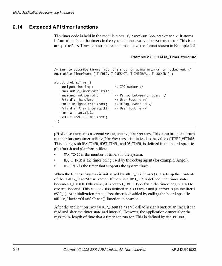
µHAL Application Programming Interfaces
2.14 Extended API timer functions
The timer code is held in the module AFSv1_4\Source\uHAL\Sources\timer.c. It stores information about the timers in the system in the uHALiv_TimerStatus vector. This is an array of uHALis_Timer data structures that must have the format shown in Example 2-8.
Example 2-8 uHALis_Timer structure
/* Enum to describe timer: free, one-shot, on-going interval or locked-out */enum uHALe_TimerState { T_FREE, T_ONESHOT, T_INTERVAL, T_LOCKED } ;
struct uHALis_Timer {unsigned int irq ; /* IRQ number */ enum uHALe_TimerState state ;unsigned int period ; /* Period between triggers */ PrHandler handler; /* User Routine */ const unsigned char *name; /* Debug, owner id */ PrHandler ClearInterruptRtn; /* User Routine */ int hw_interval:1; struct uHALis_Timer *next;
} ;
µHAL also maintains a second vector, uHALiv_TimerVectors. This contains the interrupt number for each timer. uHALiv_TimerVectors is initialized to the value of TIMER_VECTORS. This, along with MAX_TIMER, HOST_TIMER, and OS_TIMER, is defined in the board-specific platform.h and platform.s files:
• MAX_TIMER is the number of timers in the system.
• HOST_TIMER is the timer being used by the debug agent (for example, Angel).
• OS_TIMER is the timer that supports the system timer.
When the timer subsystem is initialized by uHALr_InitTimers(), it sets up the contents of the uHALiv_TimerStatus vector. If there is a HOST_TIMER defined, that timer state becomes T_LOCKED. Otherwise, it is set to T_FREE. By default, the timer length is set to one millisecond. This value is also defined in platform.h and platform.s (as the literal mSEC_1). At initialization time, a free timer is disabled by calling the board-specific uHALir_PlatformDisableTimer() function in board.c.
After the application uses a uHALr_RequestTimer() call to assign a particular timer, it can read and alter the timer state and interval. However, the application cannot alter the maximum length of time that a timer can run for. This is defined by MAX_PERIOD.
2-46 Copyright © 1999-2002 ARM Limited. All rights reserved. ARM DUI 0102G
µHAL Application Programming Interfaces
µHAL timers depend on the µHAL interrupt handling system to operate. When a timer is initialized by the application calling uHALr_InstallTimer(), the µHAL timer subsystem assigns the IRQ to the timer interrupt handler (uHALir_TimeHandler()) and enables the timer so that it can start running. The enabling of the timer is done by the board-specific uHALir_PlatformEnableTimer() function in board.c.
The timer handler is responsible for handling the timer interrupts as they occur:
1. The handler is passed the IRQ of the interrupting timer, and uses this to determine the timer that has expired.
2. After the handler has discovered which timer has expired, it calls the handler function for that timer.
3. If the timer was a single-shot timer (its state is T_ONESHOT), the timer is automatically freed by calling uHALr_FreeTimer(). Otherwise, the timer is left to run.
The timer functions are:
• uHALir_TimeHandler()
• uHALir_DisableTimer() on page 2-48
• uHALir_GetTimerInterrupt() on page 2-48.
2.14.1 uHALir_TimeHandler()
This is a high-level function that:
1. Determines which timer caused the interrupt.
2. Calls its handler.
3. Determines if the timer should be cancelled or re-enabled.
Syntax
void uHALir_TimeHandler(unsigned int irqflags)
where:
irqflags Is the currently pending interrupt.
Note This is not a user-callable function.
ARM DUI 0102G Copyright © 1999-2002 ARM Limited. All rights reserved. 2-47

µHAL Application Programming Interfaces
2.14.2 uHALir_DisableTimer()
This function disables the specified timer.
An application typically frees the timer when it has finished with it. µHAL also allows the timer to be disabled. In this case, the timer subsystem calls the platform-specific uHALir_PlatformDisableTimer() function in board.c.
Syntax
void uHALir_DisableTimer(unsigned int timer)
where:
timer Is the timer to be disabled.
2.14.3 uHALir_GetTimerInterrupt()
This function allows the application to determine the correct interrupt for the specified timer. Different target systems can assign different interrupts to the timer.
Syntax
int uHALir_GetTimerInterrupt(unsigned int timer)
where:
timer Is the timer number for which the interval is requested.
Return value
Returns one of the following:
interrupt If the timer is found, the interrupt number is returned.
-1 If the timer is not found.
2.14.4 uHALir_GetSystemTimer()
This function returns the timer number defined as the system timer.
Syntax
unsigned int uHALir_GetSystemTimer(void)
Return value
Returns the number of the IRQ for the system timer.
2-48 Copyright © 1999-2002 ARM Limited. All rights reserved. ARM DUI 0102G
µHAL Application Programming Interfaces
2.15 Extended API coprocessor access functions
These routines allow access to some of the registers in the MMU coprocessor. This allows the processor ID to be read, and the MMU/cache configuration to be read and modified.
The coprocessor access functions are:
• uHALir_CpuIdRead()
• uHALir_CpuControlRead()
• uHALir_CpuControlWrite() on page 2-50.
2.15.1 uHALir_CpuIdRead()
This function reads the processor ID. Reading from CP15, r0 returns an architecture and implementation-defined identification from the processor. If there is no cache, MMU, or write buffer, this routine returns a value equivalent to ARM7.
Syntax
unsigned int uHALir_CpuIdRead(void)
Return value
Returns the CPU type as read from the register.
2.15.2 uHALir_CpuControlRead()
This function reads from the appropriate coprocessor register to read the current state of the MMU and caches. If there is no cache, MMU, or write buffer, this routine returns 0 (all disabled).
Syntax
unsigned int uHALir_CpuControlRead(void)
Return value
Returns the MMU/cache control state as read from the register.
ARM DUI 0102G Copyright © 1999-2002 ARM Limited. All rights reserved. 2-49

µHAL Application Programming Interfaces
2.15.3 uHALir_CpuControlWrite()
This function writes to the appropriate coprocessor register to set the state of the MMU and caches. If there is no cache, MMU, or write buffer, this routine has no effect.
Syntax
void uHALir_CpuControlWrite(unsigned int controlState)
where:
controlState
Is the desired implementation-specific value for this register.
2-50 Copyright © 1999-2002 ARM Limited. All rights reserved. ARM DUI 0102G

µHAL Application Programming Interfaces
2.16 Library support functions
You can write µHAL applications that run on multiple platforms when linked with the appropriate libraries. These routines allow the application to initialize the library and to determine whether the system supports:
• PCI
• MMU or MPU
• cache
• unified or separate data and instruction caches (DCache and ICache).
The library functions are:
• uHALr_LibraryInit()
• uHALir_MMUSupported() on page 2-52
• uHALir_MPUSupported() on page 2-52
• uHALir_CacheSupported() on page 2-52
• uHALir_CheckUnifiedCache() on page 2-53.
Note For information about the PCI library query function uHALr_PCIHost (), see µHAL PCI function descriptions on page 8-17.
2.16.1 uHALr_LibraryInit()
This function performs system-specific initialization of µHAL when an application is linked to another library, such as the ADS C runtime library.
Syntax
void uHALr_LibraryInit(void)
ARM DUI 0102G Copyright © 1999-2002 ARM Limited. All rights reserved. 2-51
µHAL Application Programming Interfaces
2.16.2 uHALir_MMUSupported()
This function tests the µHAL library for MMU support.
Syntax
int uHALir_MMUSupported(void)
Return value
Returns one of the following:
1 If the library has been built for MMU access.
0 If the library has no MMU support.
2.16.3 uHALir_MPUSupported()
This function tests the µHAL library for MPU support.
Syntax
int uHALir_MPUSupported(void)
Return value
Returns one of the following:
1 If the library has been built for MPU access.
0 If the library has no MPU support.
2.16.4 uHALir_CacheSupported()
This function tests the µHAL library for cache support.
Syntax
int uHALir_CacheSupported(void)
Return value
Returns one of the following:
1 If the library has been built for cache access.
0 If the library has no cache support.
2-52 Copyright © 1999-2002 ARM Limited. All rights reserved. ARM DUI 0102G

µHAL Application Programming Interfaces
2.16.5 uHALir_CheckUnifiedCache()
This function tests the µHAL library for unified cache support.
Syntax
int uHALir_CheckUnifiedCache(void)
Return value
Returns one of the following:
1 If the library has been built for unified cache access.
0 If the library has separate DCache and ICache support.
ARM DUI 0102G Copyright © 1999-2002 ARM Limited. All rights reserved. 2-53

µHAL Application Programming Interfaces
2-54 Copyright © 1999-2002 ARM Limited. All rights reserved. ARM DUI 0102G

Chapter 3 ARM Boot Monitor
This chapter describes the boot monitor supplied with AFS. It contains the following sections:
• About the boot monitor on page 3-2
• Common commands for the boot monitor on page 3-4
• Rebuilding the boot monitor on page 3-12.
See Chapter 6 Flash Library Specification and Chapter 7 Using the ARM Flash Utilities for additional information about images in flash memory.
ARM DUI 0102G Copyright © 1999-2002 ARM Limited. All rights reserved. 3-1
ARM Boot Monitor
3.1 About the boot monitor
The boot monitor is a ROM-based monitor that communicates with a host computer using simple commands over a serial port. The boot monitor conforms to the Microsoft Standard Development Board Requirements for Windows CE Specification. The requirements of the Microsoft Harp Specification have been extended by the ARM boot monitor to aid development of new hardware. In particular, new system-specific commands have been added.
The boot monitor is a µHAL application. It uses the µHAL library to initialize the system when it runs.
3.1.1 Hardware accesses
The boot monitor accesses hardware using library calls to µHAL and other firmware libraries. This makes it generic and easily portable to platforms that support µHAL.
The boot monitor uses the following firmware libraries:
µHAL For memory initialization, heap, serial interface, timers and LEDs.
PCI For systems that support PCI, such as the Integrator.
Flash For programming images into flash and when using System Information Blocks (SIB).
3.1.2 Setting up a serial connection
To communicate with the boot monitor on the development board, you require a terminal emulator that can send raw ASCII data files (for example, Windows HyperTerminal). Connect a null modem cable to the serial port on the development board. For most boards, the terminal emulator must have the following settings:
Baud rate 38400
Data bits 8
Parity None
Stop bits 1
Flow control Xon/Xoff.
3-2 Copyright © 1999-2002 ARM Limited. All rights reserved. ARM DUI 0102G

ARM Boot Monitor
Note Refer to the appendices and hardware manuals for platform-specific details for your board. For example:
• Some boards operate at a higher Baud rate. The Intel IQ80310, for example, communicates at 115200 Baud.
• If your development board has more than one serial port, refer to the hardware manual to identify the one used with boot monitor.
• The ARM development boards have switches that select whether the boot monitor or an image in flash memory is started on reset. Refer to the documentation for your board to identify the switch settings that enable the boot monitor.
Refer to the AFS User Guide for examples of loading an image.
3.1.3 Boot monitor functions
The boot monitor supplies a base set of functions that are common across all boards. These functions:
• download images using the serial line into system memory or flash memory
• read and display words in memory
• erase system flash memory
• use the µHAL library to test all of the features available
• identify the board (including hardware and software revisions).
Board-specific extensions to the boot monitor
The boot monitor allows this functionality to be extended with board-specific commands and self-tests. Refer to the appendices for information on the boot monitor commands specific to your platform.
ARM DUI 0102G Copyright © 1999-2002 ARM Limited. All rights reserved. 3-3
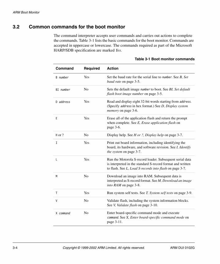
ARM Boot Monitor
3.2 Common commands for the boot monitor
The command interpreter accepts user commands and carries out actions to complete the commands. Table 3-1 lists the basic commands for the boot monitor. Commands are accepted in uppercase or lowercase. The commands required as part of the Microsoft HARP/SDB specification are marked Yes.
Table 3-1 Boot monitor commands
Command Required Action
B number Yes Set the baud rate for the serial line to number. See B, Set baud rate on page 3-5.
BI number No Sets the default image number to boot. See BI, Set default flash boot image number on page 3-5.
D address Yes Read and display eight 32-bit words starting from address. (Specify address in hex format.) See D, Display system memory on page 3-6.
E Yes Erase all of the application flash and return the prompt when complete. See E, Erase application flash on page 3-6.
H or ? No Display help. See H or ?, Display help on page 3-7.
I Yes Print out board information, including identifying the board, its hardware, and software revision. See I, Identify the system on page 3-7.
L Yes Run the Motorola S-record loader. Subsequent serial data is interpreted in the standard S-record format and written to flash. See L, Load S-records into flash on page 3-7.
M No Download an image into RAM. Subsequent data is interpreted as S-record format. See M, Download an image into RAM on page 3-8.
T Yes Run system self tests. See T, System self tests on page 3-9.
V No Validate flash, including the system information blocks. See V, Validate flash on page 3-10.
X command No Enter board-specific command mode and execute command. See X, Enter board-specific command mode on page 3-11.
3-4 Copyright © 1999-2002 ARM Limited. All rights reserved. ARM DUI 0102G

ARM Boot Monitor
Note There are additional, or modified, commands specific for individual boards. See the relevant appendix (for example, Integrator-specific commands for boot monitor on page A-6) for command details.
If the boot monitor is used on a system that requires the MMU to be active, such as the Prospector P1100, any attempt to read from or write to an invalid address causes a data exception and the boot monitor resets.
3.2.1 B, Set baud rate
This command is used to set the baud rate for the serial line used by the boot monitor. For example:
boot Monitor > b 115400
The baud rate changes immediately after the reply is sent. You must reconfigure your terminal emulator to use the new baud rate in order to send new commands.
The flow control and stop bits are not reconfigurable. See Setting up a serial connection on page 3-2 for other serial port settings.
3.2.2 BI, Set default flash boot image number
This command sets the default flash boot image to the image number specified. This modifies the boot monitor SIB. Entering the command without specifying an image number returns the number of the currently selected boot image. The image number is the logical image number, and is not based on the order of the images in flash.
Use the ARM Flash Utility to load multiple images into flash. See AFU commands on page 7-4.
Examples of this command are shown in Example 3-1.
Example 3-1 Set default boot image
boot Monitor > biCurrent Boot Image = 0boot Monitor > bi 1Current Boot Image = 0New Boot Image = 1
ARM DUI 0102G Copyright © 1999-2002 ARM Limited. All rights reserved. 3-5

ARM Boot Monitor
3.2.3 D, Display system memory
This command displays eight 32-bit words of system memory at the address given. An example of this command is shown in Example 3-2.
Example 3-2 Display system memory
boot Monitor > d 0x24000000Displaying memory at 0x240000000x24000000: 0xE59FF0180x24000004: 0xE59FF0180x24000008: 0xE59FF0180x2400000C: 0xE59FF0180x24000010: 0xE59FF0180x24000014: 0xE59FF0180x24000018: 0xE59FF0180x2400001C: 0xE59FF018
3.2.4 E, Erase application flash
This command erases all of the application flash, including all of the SIBs. You are prompted to confirm that you want to proceed or cancel the command. After the flash has been erased, the boot monitor SIB is recreated. The boot monitor SIB is changed to run image number zero on reset. An example is shown in Example 3-3.
Example 3-3 Erase system flash
boot Monitor > eErase all of the system flashAre you sure that you want to do this[Ny]? yErasing all flash
................................
................................
................................
................................
................................
................................
................................
................................
Initializing Boot Monitor System Information Block
3-6 Copyright © 1999-2002 ARM Limited. All rights reserved. ARM DUI 0102G

ARM Boot Monitor
3.2.5 H or ?, Display help
This command lists the full set of commands for this mode, as listed in Table 3-1 on page 3-4.
3.2.6 I, Identify the system
This command identifies the system on which the boot monitor is installed. It prints a message similar to that shown in Example 3-4.
Example 3-4 Identify the system
boot Monitor > iARM bootPROM [Version 1.4] Rebuilt on January 20 2002 at 12:24:07Running on a Integrator (Board revision v1.2, ARM720T Processor)Memory Size is 32M bytes, Flash size is 32M bytesCopyright (C) ARM Limited 1999. All rights reserved.Board designed by ARM LimitedHardware support provided by http://www.arm.com/For help on the available commands type ? or h
3.2.7 L, Load S-records into flash
This command downloads an image into memory and then programs it into flash. As part of the programming process it builds an appropriate flash image footer.
By default, the image is written to the location specified by the address in the S-records and labeled as image number 0. This might overwrite one or more images. When the image has been successfully written into flash, the boot monitor SIB is updated so that the default image to boot from flash is image 0.
The downloaded image is given the name BMON Loaded. The original image number 0 and any images wholly or partially overwritten are deleted.
To load a file:
1. Type l at the prompt.
2. Use the Transmit File command of your terminal emulator to send the file. If the emulator has two file transfer options, use the Send ASCII File option.
Example 3-5 on page 3-8 shows an example of the load S-records into flash command.
ARM DUI 0102G Copyright © 1999-2002 ARM Limited. All rights reserved. 3-7
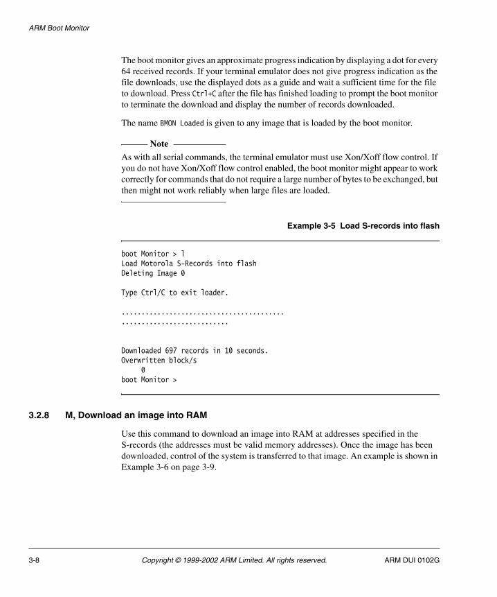
ARM Boot Monitor
The boot monitor gives an approximate progress indication by displaying a dot for every 64 received records. If your terminal emulator does not give progress indication as the file downloads, use the displayed dots as a guide and wait a sufficient time for the file to download. Press Ctrl+C after the file has finished loading to prompt the boot monitor to terminate the download and display the number of records downloaded.
The name BMON Loaded is given to any image that is loaded by the boot monitor.
Note As with all serial commands, the terminal emulator must use Xon/Xoff flow control. If you do not have Xon/Xoff flow control enabled, the boot monitor might appear to work correctly for commands that do not require a large number of bytes to be exchanged, but then might not work reliably when large files are loaded.
Example 3-5 Load S-records into flash
boot Monitor > lLoad Motorola S-Records into flashDeleting Image 0
Type Ctrl/C to exit loader.
.........................................
...........................
Downloaded 697 records in 10 seconds.Overwritten block/s
0boot Monitor >
3.2.8 M, Download an image into RAM
Use this command to download an image into RAM at addresses specified in the S-records (the addresses must be valid memory addresses). Once the image has been downloaded, control of the system is transferred to that image. An example is shown in Example 3-6 on page 3-9.
3-8 Copyright © 1999-2002 ARM Limited. All rights reserved. ARM DUI 0102G
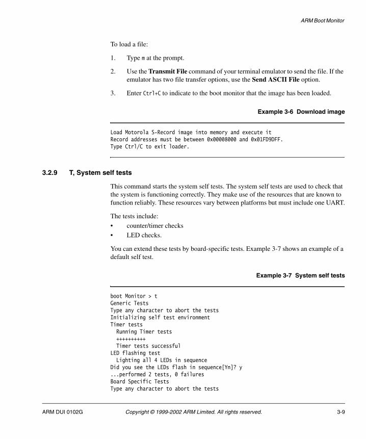
ARM Boot Monitor
To load a file:
1. Type m at the prompt.
2. Use the Transmit File command of your terminal emulator to send the file. If the emulator has two file transfer options, use the Send ASCII File option.
3. Enter Ctrl+C to indicate to the boot monitor that the image has been loaded.
Example 3-6 Download image
Load Motorola S-Record image into memory and execute itRecord addresses must be between 0x00008000 and 0x01FD9DFF.Type Ctrl/C to exit loader.
3.2.9 T, System self tests
This command starts the system self tests. The system self tests are used to check that the system is functioning correctly. They make use of the resources that are known to function reliably. These resources vary between platforms but must include one UART.
The tests include:
• counter/timer checks
• LED checks.
You can extend these tests by board-specific tests. Example 3-7 shows an example of a default self test.
Example 3-7 System self tests
boot Monitor > tGeneric TestsType any character to abort the testsInitializing self test environmentTimer testsRunning Timer tests++++++++++Timer tests successful
LED flashing testLighting all 4 LEDs in sequence
Did you see the LEDs flash in sequence[Yn]? y...performed 2 tests, 0 failuresBoard Specific TestsType any character to abort the tests
ARM DUI 0102G Copyright © 1999-2002 ARM Limited. All rights reserved. 3-9

ARM Boot Monitor
Keyboard/mouse tests
Initializing KMI interface==========================
kmi_handler(3)kmi_handler(3)KMI: wrote FFkmi_handler(4)kmi_handler(4)KMI: wrote FF
Port 0: Device unsupported or absentPort 1: Device unsupported or absent
...performed 1 tests, 0 failures
3.2.10 V, Validate flash
This command validates and displays the contents of the application flash and the SIBs. It flags any errors that it finds. An example is shown in Example 3-8. The name BMON Loaded is given to any image that is loaded by the boot monitor.
Example 3-8 Validate flash
boot Monitor > vThere are 256 128Kbyte blocks of flash:
Images found============Block Size ImageNo Name Compress----- ---- ------- ---- -------- 0 1 124 Angel (0x24000000-0x2401FFEC) 20 5 120 slideshow Y (0x24280000-0x2411FFEC) 64 1 123 hello (0x24800000-0x2481FFEC)
System Information Blocks=========================Address Owner Size Idx Rev------- ----- ---- --- ---0x25FE0000 ARM Boot Monitor 312 0 28
boot Monitor >
3-10 Copyright © 1999-2002 ARM Limited. All rights reserved. ARM DUI 0102G

ARM Boot Monitor
3.2.11 X, Enter board-specific command mode
This mode is used to process board-specific (or extended) commands. If you enter a single X, the prompt changes to show that you are in the extended mode. The board-specific menu provides a command that returns you to the normal command processing mode. To exit board-specific mode, enter an X in extended mode.
You can execute a single board-specific command by entering a command on the same line as X (with a space in between). Refer to the appendices for details of board-specific commands.
ARM DUI 0102G Copyright © 1999-2002 ARM Limited. All rights reserved. 3-11

ARM Boot Monitor
3.3 Rebuilding the boot monitor
Use the project files or makefile, in the bootMonitor subdirectory of the Source directory for your board to rebuild the boot monitor library.
For example, if you installed to AFSv1_4 use either bootMonitor.mcp or makefile in AFSv1_4\Source\bootMonitor\Build\Integrator.b to rebuild the library for the Integrator board.
Note A prebuilt version of the latest boot monitor and Angel image is provided in the AFSv1_4\Images directory.
For general information on makefiles and directory structure, see Rebuilding libraries on page 11-3.
3-12 Copyright © 1999-2002 ARM Limited. All rights reserved. ARM DUI 0102G
Chapter 4 Operating Systems and µHAL
This chapter describes how operating systems can run applications on an ARM-based evaluation board that has previously had µHAL ported to it. It contains the following sections:
• About porting operating systems on page 4-2
• Simple operating systems on page 4-3
• Complex operating system on page 4-11.
ARM DUI 0102G Copyright © 1999-2002 ARM Limited. All rights reserved. 4-1

Operating Systems and µHAL
4.1 About porting operating systems
µHAL provides a basic API that enables simple applications to run on a variety of ARM-based development systems. You can also use it as the basis of a port of an operating system.
There are two types of operating system that can use µHAL:
• Simple threaded operating systems that run directly out of physical memory. (The physical memory can have a fixed remapping however.) You can often link simple operating systems directly to µHAL. The operating system then functions as a µHAL application. The example of this type of operating system used in this chapter is µC/OS-II. It runs without further porting effort on any ARM evaluation board that has had µHAL ported to it. This is why µC/OS-II is often the first operating system to run on a new ARM-based platform.
• Complex operating systems that utilize virtual memory (possibly using demand paging mechanisms). You cannot link these more complex operating systems directly with µHAL but they can reuse parts of µHAL. Reusing µHAL makes porting simpler than it otherwise might be. An example of this type of operating system is Linux. Simple operating systems on page 4-3 and Complex operating system on page 4-11 discuss these two types of operating system.
4-2 Copyright © 1999-2002 ARM Limited. All rights reserved. ARM DUI 0102G
Operating Systems and µHAL
4.2 Simple operating systems
This section describes how ARM-specific porting code is used to initialize µC/OS-II and to allow µC/OS-II to carry out context switching.
For a simple operating system to run directly over µHAL, the following conditions must be met:
• The OS must have a fixed memory map. The memory map must be consistent with the default map defined by µHAL.
• The OS must use context switching of tasks or threads at the end of an interrupt (usually a periodic timer) or when it exits from a system call.
• The OS must be capable of being built using the ARM software development tools.
This type of operating system is isolated from the specific hardware details of the development platform because it utilizes µHAL code for system initialization, timer, and interrupt handling. It is the ARM-specific porting code that bridges the gap between the operating system and µHAL.
4.2.1 About µC/OS-II
µC/OS-II is a portable, ROM-able, pre-emptive, real-time, multitasking kernel that can manage up to 63 tasks. µC/OS-II is comparable in performance to many commercially available kernels. The ARM Firmware Suite includes a port of µC/OS-II made to the ARM architecture using the µHAL interfaces. µC/OS-II provides the following features:
• creating and managing up to 63 tasks
• creating and managing semaphores
• delaying tasks for a specified number of ticks or amount of time
• locking and unlocking the scheduler
• servicing interrupts
• changing the priority of tasks
• deleting tasks
• suspending and resuming other tasks from within a task
• managing message mailboxes and queues for inter-task communications
• managing fixed-sized memory blocks
• managing a 32-bit system clock.
ARM DUI 0102G Copyright © 1999-2002 ARM Limited. All rights reserved. 4-3

Operating Systems and µHAL
Note If you want to use µC/OS-II within a product or wish to redistribute µC/OS-II you must seek a license arrangement with Micrium Inc., the owners of µC/OS-II.
You do not have to understand µC/OS-II completely in order to understand the principles involved. If you want more information on the OS, read Micro-C/OS-II, The Real-Time Kernel.
4.2.2 Initializing the operating system
The entry point to a simple operating system, as it is for all other µHAL applications, is the main() routine. Example 4-1 shows this using the ping.c example program in µC/OS-II.
Example 4-1 Operating system initialization - main()
/* Main function. */int main(int argc, char **argv){ char Id1 = '1'; char Id2 = '2';
/* do target (uHAL based ARM system) initialisation */ ARMTargetInit();
OSInit(); /* needed by uC/OS */OSTimeSet(0);
/* create the semaphores */Sem1 = OSSemCreate(1);Sem2 = OSSemCreate(1);
/* create the tasks in uC/OS and assign decreasing priority to them */OSTaskCreate(Task1, (void *)&Id1, (void *)&Stack1[STACKSIZE - 1], 1);OSTaskCreate(Task2, (void *)&Id2, (void *)&Stack2[STACKSIZE - 1], 2);
/* Start the (uHAL based ARM system) system running */ ARMTargetStart();
OSStart(); /* never reached */
}
4-4 Copyright © 1999-2002 ARM Limited. All rights reserved. ARM DUI 0102G

Operating Systems and µHAL
When the main() routine is called, µHAL has already initialized the system. For example, address mapping is turned on. The operating system can therefore initialize itself and start running:
1. The first call from main() is to µHAL-specific routine ARMTargetInit() (in os_cpu_c.c) to set things up. OSInit(), in the case of µC/OS-II, initializes the operating system state (for example its priority map).
2. main() creates several threads. Each thread has an area of stack that is initialized with an initial register set. The initial PC for a task contains the address of the thread routine (in this case Task1() and Task2() respectively).
3. Finally, main() starts the operating system with calls to the µHAL-specific code ARMTargetStart() and the μC/OS-II function OSStart(). See Example 4-2 and Example 4-3 on page 4-6.
ARMTargetStart() starts the system timer. The system timer functions as a periodic timer and issues an interrupt request every millisecond. When the interrupts occur, the operating system controls whether or not it requires a context switch.
OSStart() selects the highest priority task that is runnable (in this case Task1) and runs it by loading its registers from its stack.
Example 4-2 Operating system initialization - ARMTargetInit()
#define BUILD_DATE "Date: " __DATE__ "\n"
/* Initialize an ARM Target board */ void ARMTargetInit(void) {
/* ---- Tell the world who we are ----------------- */ uHALr_printf("uCOS-II Running on a") ;
#if defined(EBSA285)uHALr_printf("n EBSA-285 (21285 evaluation board)\n") ;
#elif defined(BRUTUS) uHALr_printf(" Brutus (SA-1100 verification platform)\n") ;
#else uHALr_printf("%s\n, ucosii_banner") ;
#endif uHALr_printf(uHAL_VERSION_STRING); uHALr_printf("\n") ; uHALr_printf(BUILD_DATE); uHALr_printf("\n") ;
#ifdef DEBUG uHALr_printf("Initialising target\n");
#endif uHALr_ResetMMU(); /* ---- disable the MMU -- */
ARM DUI 0102G Copyright © 1999-2002 ARM Limited. All rights reserved. 4-5
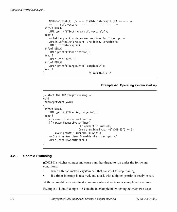
Operating Systems and µHAL
ARMDisableInt(); /* ---- disable interrupts (IRQs------ */ /* ---- soft vectors ------------------------- */
#ifdef DEBUG uHALr_printf("Setting up soft vectors\n");
#endif /* Define pre & post-process routines for Interrupt */ uHALir_DefineIRQ(IrqStart, IrqFinish, (PrVoid) 0); uHALr_InitInterrupts();
#ifdef DEBUG uHALr_printf("Timer init\n");
#endif uHALr_InitTimers();
#ifdef DEBUG uHALr_printf("targetInit() complete\n");
#endif } /* targetInit */
Example 4-3 Operating system start up
/* start the ARM target running */voidARMTargetStart(void){ #ifdef DEBUG
uHALr_printf("Starting target\n") ; #endif
/* request the system timer */if (uHALr_RequestSystemTimer(
PrHandler) OSTimeTick,(const unsigned char *)"uCOS-II") <= 0)
uHALr_printf("Timer/IRQ busy\n");/* Start system timer & enable the interrupt. */uHALr_InstallSystemTimer();
}
4.2.3 Context Switching
µC/OS-II switches context and causes another thread to run under the following conditions:
• when a thread makes a system call that causes it to stop running
• if a timer interrupt is received, and a task with a higher priority is ready to run.
A thread might be caused to stop running when it waits on a semaphore or a timer.
Example 4-4 and Example 4-5 contain an example of switching between two tasks.
4-6 Copyright © 1999-2002 ARM Limited. All rights reserved. ARM DUI 0102G
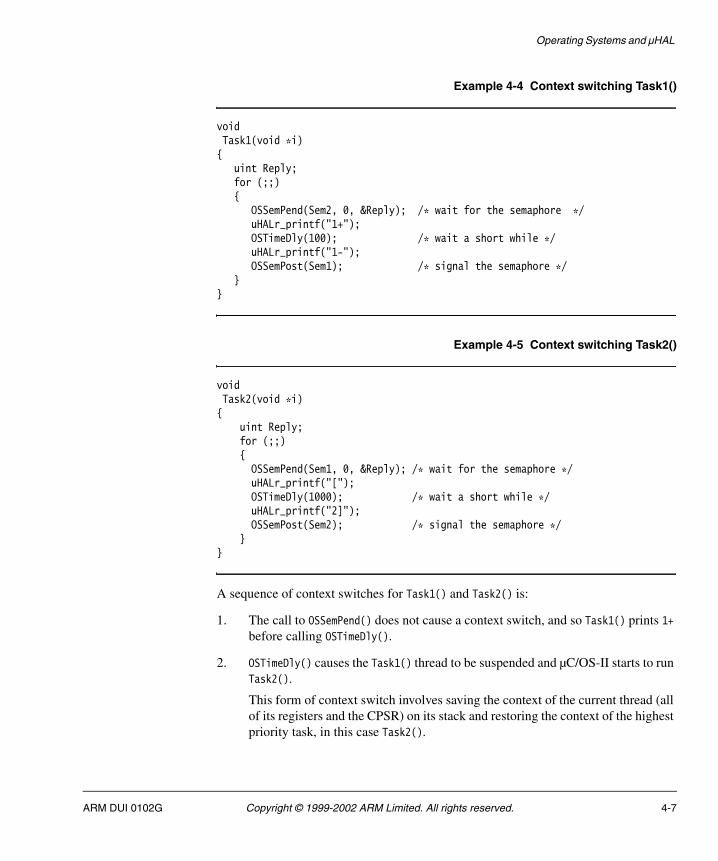
Operating Systems and µHAL
Example 4-4 Context switching Task1()
voidTask1(void *i){
uint Reply;for (;;){
OSSemPend(Sem2, 0, &Reply); /* wait for the semaphore */uHALr_printf("1+");OSTimeDly(100); /* wait a short while */uHALr_printf("1-");OSSemPost(Sem1); /* signal the semaphore */
}}
Example 4-5 Context switching Task2()
voidTask2(void *i){
uint Reply;for (;;){OSSemPend(Sem1, 0, &Reply); /* wait for the semaphore */uHALr_printf("[");OSTimeDly(1000); /* wait a short while */uHALr_printf("2]");OSSemPost(Sem2); /* signal the semaphore */
}}
A sequence of context switches for Task1() and Task2() is:
1. The call to OSSemPend() does not cause a context switch, and so Task1() prints 1+ before calling OSTimeDly().
2. OSTimeDly() causes the Task1() thread to be suspended and µC/OS-II starts to run Task2().
This form of context switch involves saving the context of the current thread (all of its registers and the CPSR) on its stack and restoring the context of the highest priority task, in this case Task2().
ARM DUI 0102G Copyright © 1999-2002 ARM Limited. All rights reserved. 4-7
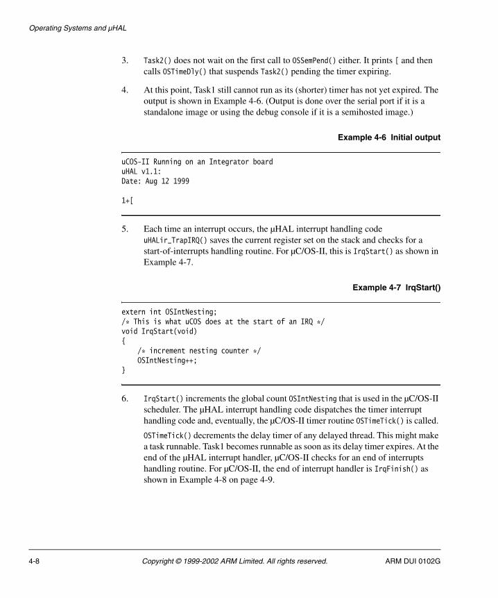
Operating Systems and µHAL
3. Task2() does not wait on the first call to OSSemPend() either. It prints [ and then calls OSTimeDly() that suspends Task2() pending the timer expiring.
4. At this point, Task1 still cannot run as its (shorter) timer has not yet expired. The output is shown in Example 4-6. (Output is done over the serial port if it is a standalone image or using the debug console if it is a semihosted image.)
Example 4-6 Initial output
uCOS-II Running on an Integrator boarduHAL v1.1: Date: Aug 12 1999
1+[
5. Each time an interrupt occurs, the µHAL interrupt handling code uHALir_TrapIRQ() saves the current register set on the stack and checks for a start-of-interrupts handling routine. For µC/OS-II, this is IrqStart() as shown in Example 4-7.
Example 4-7 IrqStart()
extern int OSIntNesting;/* This is what uCOS does at the start of an IRQ */void IrqStart(void){
/* increment nesting counter */OSIntNesting++;
}
6. IrqStart() increments the global count OSIntNesting that is used in the µC/OS-II scheduler. The µHAL interrupt handling code dispatches the timer interrupt handling code and, eventually, the µC/OS-II timer routine OSTimeTick() is called.
OSTimeTick() decrements the delay timer of any delayed thread. This might make a task runnable. Task1 becomes runnable as soon as its delay timer expires. At the end of the µHAL interrupt handler, µC/OS-II checks for an end of interrupts handling routine. For µC/OS-II, the end of interrupt handler is IrqFinish() as shown in Example 4-8 on page 4-9.
4-8 Copyright © 1999-2002 ARM Limited. All rights reserved. ARM DUI 0102G

Operating Systems and µHAL
Example 4-8 IrqFinish()
/* This is what uCOS does at the end of an IRQ */extern int OSIntExit(void);extern void IRQContext(void); /* post DispatchIRQ processing */PrVoid IrqFinish(void){
/* call exit routine - return TRUE if a context switch is needed */
if (OSIntExit() == TRUE)return (IRQContext);
return ((PrVoid) 0);}
7. IrqFinish() calls OSIntExit() to determine if a context switch is necessary. If a context switch is necessary, IrqFinish() returns the address of IRQContext() (the µC/OS-II interrupt-specific context switching routine).
Normally, the µHAL interrupt handling routine restores the saved registers from the stack and returns from the interrupt. Because the end-of-interrupt routine returned an address, IrqFinish() calls the µC/OS-II interrupt context switching routine with the saved registers still on the stack.
Note The usage of registers on the stack must be the same for both µC/OS-II and
µHAL.
8. When Task1() runs it prints 1-, posts to the Task2() semaphore (incrementing it) and waits on its own semaphore.
9. When Task2() is selected to run (after its delay timer expires), it prints 2] and posts to the Task1() semaphore. This allows Task1() to run, causing the whole cycle to repeat as shown in Example 4-9.
Example 4-9 Later output
uHAL v1.1: Date: Aug 12 1999
1+[1-2]1+[1-2]1+[1-2]1+[1-2]1+[1-2]1+[1-2]1+[1-
ARM DUI 0102G Copyright © 1999-2002 ARM Limited. All rights reserved. 4-9
Operating Systems and µHAL
4.2.4 Efficiency considerations
The method of switching context during an interrupt is not particularly efficient because it involves several calls into C code. It does, however, have the advantage of being highly portable.
If efficiency is a constraint, the port of an operating system can use its own interrupt handling code instead of the µHAL routines:
• An initial step to improving efficiency is to replace the µHAL interrupt handler uHALir_TrapIRQ() but still call the C-based interrupt and timer handling routines provided by µHAL. If the replacement interrupt handler uses the READ_INT macro, it is not dependent on the version of the ARM evaluation board that is used. This also has the advantage that the stack usage can differ between the operating system and µHAL.
• You can make additional improvement if, once a timer is started, it is periodic and does not require any further intervention. The operating system can reuse the interrupt and no additional calls to µHAL are required once the timer is running.
• The final option is to reuse parts of µHAL in a board-specific port and tailor the code to the operating system. This approach is not very portable, but you can use it to improve efficiency.
4-10 Copyright © 1999-2002 ARM Limited. All rights reserved. ARM DUI 0102G
Operating Systems and µHAL
4.3 Complex operating system
Complex operating systems cannot directly use µHAL but they can do one or more of the following:
• reuse its definitions and some of its board-specific code
• use a µHAL-based image as a loader or initializer.
4.3.1 Reusing definitions
Reusing definitions usually means using the definitions from platform.h. This gives the operating system definitions of where in the physical memory map registers are located, as well as bit settings for those registers. For example, platform.h for the Integrator platform defines the physical address of the LED and switch register set as shown in Example 4-10.
Example 4-10 LED and switch addresses
#define INTEGRATOR_DBG_ALPHA_OFFSET 0x00 #define INTEGRATOR_DBG_LEDS_OFFSET 0x04 #define INTEGRATOR_DBG_SWITCH_OFFSET 0x08
#define INTEGRATOR_DBG_BASE 0x1A000000 #define INTEGRATOR_DBG_ALPHA (INTEGRATOR_DBG_BASE + INTEGRATOR_DBG_ALPHA_OFFSET) #define INTEGRATOR_DBG_LEDS (INTEGRATOR_DBG_BASE + INTEGRATOR_DBG_LEDS_OFFSET) #define INTEGRATOR_DBG_SWITCH (INTEGRATOR_DBG_BASE + INTEGRATOR_DBG_SWITCH_OFFSET)
This definition can be directly used if the address map remains physical.
If the operating system runs out of virtual memory, there must be a further definition. If you port Linux to Integrator for example, all of the Integrator registers are mapped to virtual address 0xF0000000 and placed together using the following definition:
#define IO_BASE 0xF0000000 #define IO_ADDRESS(x) ( (x>>4) + IO_ BASE )
The virtual address of Integrator switch registers becomes ((0x1A000008 >> 4) + 0xF0000000) or 0xF1A00000.
A Linux port to the Integrator platform would have each bank of registers mapped to its own virtual address. The LED offset from the debug base is defined in platform.h as INTEGRATOR_DBG_LEDS_OFFSET and has a value of 4 bytes.
You can find the LEDs using this address:
IO_ADDRESS(INTEGRATOR_DBG_BASE) + INTEGRATOR_DBG_LEDS_OFFSET
ARM DUI 0102G Copyright © 1999-2002 ARM Limited. All rights reserved. 4-11
Operating Systems and µHAL
The bit settings can then be used as normal. For example, bit 0 is the green LED. There are also defines for the LEDs, GREEN_LED as shown in Example 4-11.
Example 4-11 LED bit values
#define uHAL_LED_ON 1 #define uHAL_LED_OFF 0 #define uHAL_NUM_OF_LEDS 4 #define GREEN_LED 0x01 #define YELLOW_LED 0x02 #define RED_LED 0x04 #define GREEN_LED_2 0x08 #define ALL_LEDS 0x0F
#define LED_BANK INTEGRATOR_DBG_LEDS
4.3.2 µHAL-based loader application
A pure µHAL application is used to initialize the system and then to load the operating system. For example, you can load the binary image of a Linux kernel into flash using the ARM Flash Utility.
A µHAL-based loader application initializes the Integrator PCI subsystem and then copies the kernel into memory before transferring control to it. The kernel does not require any PCI setup code, instead it scans the PCI subsystem discovering how the µHAL application set it up. This removes the need for the kernel to understand the details of setting up the V3 PCI chip and how to route interrupts on the Integrator platform.
You can also modify the µHAL loader/initialization application to pass a data structure to the operating system kernel that describes the system.
4-12 Copyright © 1999-2002 ARM Limited. All rights reserved. ARM DUI 0102G

Chapter 5 Angel
This chapter describes the function of Angel on development boards, and how µHAL and Angel debug monitor sources are related. The code required to port Angel to a system that already has µHAL is covered in detail. The chapter contains the following sections:
• About Angel on page 5-2
• µHAL-based Angel on page 5-9
• Building a µHAL-based Angel on page 5-11
• Source file descriptions on page 5-13
• Device drivers on page 5-22
• Developing applications with Angel on page 5-26
• Angel in operation on page 5-33
• Angel communications architecture on page 5-46.
For more information on using Angel with a debugger, see the documentation provided ADS.
ARM DUI 0102G Copyright © 1999-2002 ARM Limited. All rights reserved. 5-1
Angel
5.1 About Angel
This section describes how µHAL and the Angel debug monitor sources are related. It recommends a number of coding practices that allow Angel and µHAL to be quickly and easily ported to ARM-based systems, and for semihosted µHAL applications to run with Angel.
The Angel debug monitor uses a serial line or Ethernet to communicate with a development host running an ARM debugger. The debugger uses the Angel Debug Protocol (ADP) to send requests to Angel to, for example:
• download images
• set breakpoints
• examine registers and variables.
These functions are described in detail in the documentation supplied with your debugger. To carry out these functions, Angel uses the physical system resources, such as interrupts, serial ports, and memory (for stack and context storage).
Building a fully functional µHAL-based Angel is simplified if you take a series of small steps. This is where µHAL is used. Port µHAL to your platform first and verify that:
• memory management is functioning correctly
• LEDs are functioning
• the serial port is operating
• interrupts are being generated.
These steps can be performed one at a time. When you have verified that the board is functioning correctly at this level, re-use the code within Angel.
It is usually better to build on an example of an existing port, than to start again. Most of the ports of Angel in ARM Firmware Suite are based on reusing µHAL sources. These are targeted at the Integrator and the Prospector development systems. This chapter uses both of these sources as examples.
5.1.1 Angel system resource requirements
Where possible, Angel resource usage can be statically configured at compile and link time. For example, the memory map, exception handlers, and interrupt priorities are all fixed at compile and link time.
5-2 Copyright © 1999-2002 ARM Limited. All rights reserved. ARM DUI 0102G
Angel
System resources
Angel requires the following non-configurable resources:
• Two ARM Undefined Instructions (for big-endian or little-endian versions, however only a little-endian version of Angel is supplied with AFS)
• One Thumb Undefined Instruction
• One ARM SWI with value 0x123456
• One Thumb SWI with value 0xAB.
Note You can reconfigure the value of the ARM and Thumb SWI, but this is not
necessary or recommended.
ROM and RAM requirements
Angel requires ROM or Flash memory to store the debug monitor code, and RAM to store data. The amount of ROM, Flash, and RAM required varies depending on the development board you are using.
The standard RAM on Integrator and Prospector is sufficient to run Angel. The RAM on Prospector cannot normally be upgraded.
Exception vectors
Angel requires some control over the ARM exception vectors. Exception vectors are initialized by Angel, and are not written to after initialization. This supports systems with ROM at address 0, where the vectors cannot be overwritten.
Note An application that chains the vectors must unchain them on exit, or the target must be reset, so that the exceptions do not crash the machine when the application is overwritten.
Angel installs itself by initializing the vector table so that it takes control of the target when an exception occurs. For example, debug communications from the host cause an interrupt that halts the application and calls the appropriate code within Angel.
ARM DUI 0102G Copyright © 1999-2002 ARM Limited. All rights reserved. 5-3

Angel
Interrupts
Angel requires use of at least one interrupt to support communication between the host and target systems. You can set up Angel to use:
• IRQ
• FIQ
• both IRQ and FIQ.
Angel normally uses FIQ with µHAL using IRQ. However, some ports, such as the Prospector P720T and Intel 80310, chain IRQs (Angel and µHAL sharing IRQs).
Stacks
Angel requires control over its own Supervisor stack. If you want to make Angel calls from your application you must set up your own stacks. Applications built with the C library initialize stacks automatically. Refer to Developing applications with Angel on page 5-26 for more information.
Angel also requires that the current stack pointer points to a few words of usable full descending stack whenever an exception is possible, because the Angel exception return code uses the application stack to return.
Angel and cache memory
Angel is built for the processor in use and consequently recognizes whether the processor supports cache flushing. On systems where different processors might be used, Angel can be built to recognize the processor in use, but the current builds do not support this. If you disable the cache when running Angel, your applications might run several times slower than with cache (the maximum serial line speed might also be reduced.) However, the debugging process is not otherwise affected.
If you want your applications to run at full speed with cache memory, use Multi-ICE instead of Angel. (Multi-ICE is a separate hardware product and is not supplied with AFS.)
5.1.2 Thumb support
The prebuilt Angel image and the default Angel build support Thumb programs only on Integrator. Switch Thumb support off using the THUMB_SUPPORT=0 define.
5-4 Copyright © 1999-2002 ARM Limited. All rights reserved. ARM DUI 0102G

Angel
5.1.3 Angel system features
Angel provides the following functionality:
• Debug support
• C library semihosting support
• Communications support on page 5-6
• Task management on page 5-6
• Exception handling on page 5-7.
Debug support
Angel provides the following basic debug support:
• reporting and modifying memory and processor status
• downloading applications to the target system
• setting breakpoints.
Refer to Angel debugger functions on page 5-35 for more information on how Angel performs these functions.
C library semihosting support
Angel uses a SoftWare Interrupt (SWI) mechanism to enable applications linked with the ARM C and C++ libraries to make semihosting requests. Semihosting requests are requests such as open a file on the host, or get the debugger command line, that must be communicated to the host to be carried out. These requests are referred to as semihosting because they rely on code in the host machine to carry out the request.
ADS provides prebuilt ANSI C libraries that you can link with your application. Specific C library functions, such as input/output, use the SWI mechanism to pass the request to the host system.
These libraries are used by default when you link code that calls ANSI C library functions. Refer to the description of the C libraries in the ADS documentation for more information.
Angel uses a single SWI to request semihosting operations. By default, the SWI is 0x123456 in ARM state and 0xAB in Thumb state. You can change these numbers, but that is not recommended.
ARM DUI 0102G Copyright © 1999-2002 ARM Limited. All rights reserved. 5-5
Angel
If semihosting support is not required you can disable it by setting the semihosting_enabled variable in the ARM debuggers:
• In armsd set:
$semihosting_enabled = 0
• In ADW or ADU, select Debugger Internals from the View menu to view and edit the variable.
• In AXD, use the Processor properties to view and edit the variable.
Refer to the description of ARM debuggers in the documentation supplied with ADS for more information.
Communications support
Angel communicates using Angel Debug Protocol (ADP), and uses channels to allow multiple independent sets of messages to share a single communications link. Angel provides an error-correcting communications protocol over a serial connection from the host to the target board. The target has Angel resident on the board. See Angel communications architecture on page 5-46.
The host and target system channel managers ensure that logical channels are multiplexed reliably. The device drivers detect and reject corrupted data packets. The channel managers monitor the overall flow of data and store transmitted data in buffers, in case retransmission is required. Refer to Angel communications architecture on page 5-46 for more information.
The Angel Device Driver Architecture uses Angel task management functionality to control packet processing and to ensure that interrupts are not disabled for long periods of time.
You can write device drivers to use alternative devices for debug communication, such as a ROMulator. You can extend Angel to support different peripherals, or your application can address devices directly.
Task management
All Angel operations, including communications and debug operations, are controlled by Angel task management. Angel task management:
• ensures that only a single operation is carried out at any time
• assigns task priorities and schedules tasks accordingly
• controls the Angel environment processor mode.
Refer to Angel task management on page 5-37 for more information.
5-6 Copyright © 1999-2002 ARM Limited. All rights reserved. ARM DUI 0102G
Angel
Exception handling
Angel exception handling provides the basis for debug, C library semihosting, communications, and task management. Angel installs exception handlers for each ARM exception type except Reset:
SWI Angel installs a SWI exception handler to support semihosting requests, and to allow applications and Angel to enter Supervisor mode.
Undefined Angel uses three Undefined Instructions to set breakpoints in code. Refer to Setting breakpoints on page 5-30 for more information.
Data, Prefetch Abort
Angel installs basic Data and Prefetch Abort handlers. These handlers report the exception to the debugger, suspend the application, and pass control back to the debugger.
FIQ, IRQ Angel installs IRQ and FIQ handlers that enable Angel communications to run off either, or both types of interrupt. If you have a choice you must use IRQ for Angel communications, and FIQ for your own interrupt requirements.
You can chain your own exception handlers for your own purposes. Refer to Chaining exception handlers on page 5-29 for more information.
5.1.4 Using Angel with a debugger
A typical Angel system has two main components that communicate through a physical link, such as a serial cable:
Debugger The debugger runs on the host computer. It gives instructions to Angel and displays the results obtained from it. All ARM debuggers support Angel, and you can use any other debugging tool that supports the communications protocol used by Angel.
Angel debug monitor
The Angel debug monitor runs alongside the application being debugged on the target platform.
ARM DUI 0102G Copyright © 1999-2002 ARM Limited. All rights reserved. 5-7

Angel
Once you have installed Angel into the flash memory, you can use it with your debugger. The way you connect to Angel depends on the debugger you are using:
armsd The command line must be of the form:
armsd -adp -port s=1 -linespeed 38400 image.axf
AXD for ADS 1.0 (or higher)
See the debugger documentation supplied with ADS.
You can test whether Angel has installed by setting a terminal emulator to 9600 baud, setting the boot image selector switch to boot the Angel image, and resetting the board. Angel attempts to communicate with the debugger over the serial port. The terminal emulator displays some symbols and then the Angel banner. See the AFS User Guide for more information on using Angel with a Integrator board.
5.1.5 Downloading Angel to a development board
Some development boards come with Angel installed. If your board does not have Angel already installed, you must download the Angel image for your board and processor. Prebuilt images for the boot monitor and Angel are in the AFS1_4\Images directory. You can also customize a version of Angel and download it to the application flash area using one of the download utilities supplied for your platform. See the relevant appendix for more details.
5-8 Copyright © 1999-2002 ARM Limited. All rights reserved. ARM DUI 0102G

Angel
5.2 µHAL-based Angel
Most of the Angel code is the same for µHAL-based Angels as any other (non-µHAL) Angel. The only difference is that µHAL-based Angels utilize system-dependent code that is held within µHAL. Angel still requires the same set of macros, source code, and definitions that it did before, but now it imports some of these definitions from µHAL source files.
You can download one of the prebuilt Angel images, or rebuild Angel and download your modified version.
If you rebuild Angel, the version string is Unreleased. This indicates that the copy of Angel was built outside of ARM. You can edit the version string information in the source files in banner.c and banner.h to display your own version code.
5.2.1 Source directory for Angel
A particular board is supported by code held in the relevant board-specific directory of µHAL. For example, the sources that relate to Integrator are all held in the directory uHAL\Boards\INTEGRATOR. This set of sources consists of:
platform.h and platform.s
These files contain definitions of the board, including its memory layout, and devices.
driver.s This file contains low-level assembly code needed for the board to function.
target.s This file contains ARM assembly macros that are used within µHAL. For example, to switch the memory map or light a particular LED. Routines in driver.s often use these macros too.
memmap.s This file describes (in tabular form) the memory map for a particular system. This includes where in virtual memory, the various areas of physical memory are mapped.
board.c This file contains C routines that support the operation of the board. For example, the PCI Configuration space access routines for Integrator are stored here.
ARM DUI 0102G Copyright © 1999-2002 ARM Limited. All rights reserved. 5-9

Angel
5.2.2 Angel sources and definitions
A µHAL-based Angel requires extra sources and definitions. For example, the angel\Integrator directory contains:
banner.h This file provides the startup banner displayed by this Angel.
devices.c This file describes the set of devices available to Angel for this board.
makelo.c This file allows variables to be shared between both the .c and the .s assembler files. It produces an assembler header file called lolevel.s.
timerdev.c This file implements Angel timers for the Integrator platform. This timer is used for profiling and for polled device drivers (for example, Ethernet devices).
integrator.h This file contains Integrator-specific Angel definitions, including platform.h.
devconf.h This file is the main configuration file of the target image. It describes the uses that Angel makes of the system resources, for example stack memory.
serial.c This file implements the serial driver for Angel on this system.
ambauart.h This file contains definitions for the serial interface hardware.
The angel\Prospector directory contains similar files. The use of these files by Angel is described in Building a µHAL-based Angel on page 5-11.
5-10 Copyright © 1999-2002 ARM Limited. All rights reserved. ARM DUI 0102G
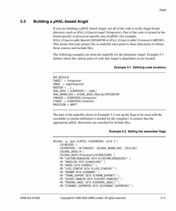
Angel
5.3 Building a µHAL-based Angel
If you are building a µHAL-based Angel, not all of the code is in the Angel board directory (such as AFSv1_4\Source\angel\Integrator). Part of the code is located in the board-specific or processor-specific area of µHAL (for example, AFSv1_4\Source\uHAL\Boards\INTEGRATOR or AFSv1_4\Source\uHAL\Processors\ARM720T). This means that your project file or makefile must point to these directories to obtain those sources and include files.
The following examples are from the makefile for the Integrator Angel. Example 5-1 defines where the various parts of code that Angel is dependent on are located.
Example 5-1 Defining code locations
ADS_BUILD=0TARGET = IntegratorIMAGE = angIntegratorROOTDIR = ../..UHAL_BASE = $(ROOTDIR)/../uHAL/UHAL_BOARD_DIR = $(UHAL_BASE)/Boards/INTEGRATORTARGDIR = $(ROOTDIR)/IntegratorETHDIR = $(ROOTDIR)/ethernetPROCESSOR = ARM7T
The part of the makefile shown in Example 5-2 sets up the flags to be used with the assembler (a similar definition is needed for the compiler). It ensures that the appropriate µHAL directories are searched for include files.
Example 5-2 Setting the assembler flags
AFLAGS= -g -apcs $(APCS) $(ASENDIAN) -arch 4 \ -I$(OBJDIR) \ -I$(ROOTDIR) -I$(TARGDIR) -I$(UHAL_BOARD_DIR) -I$(CLIB)\ -I$(UHAL_BASE)/h \ -I$(UHAL_BASE)/Processors/$(PROCESSOR) \ -PD "LOGTERM_DEBUGGING SETA $(LOGTERM_DEBUGGING)" \ -PD "ANGELVSN SETA $(ANGELVSN)" \ -PD "DEBUG SETA $(DEBUG)" \ -PD "LATE_STARTUP SETA $(LATE_STARTUP)" \ -PD "ROADDR SETA $(ROADDR)" \ -PD "THUMB_SUPPORT SETA $(THUMB_SUPPORT)" \ -PD "ASSERT_ENABLED SETA $(ASSERT_ENABLED)" \ -PD "MINIMAL_ANGEL SETA $(MINIMAL_ANGEL)" \ -PD "ETHERNET_SUPPORTED SETA $(ETHERNET_SUPPORTED)" \
ARM DUI 0102G Copyright © 1999-2002 ARM Limited. All rights reserved. 5-11
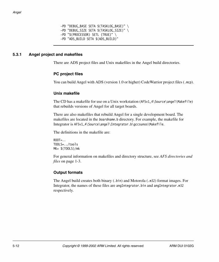
Angel
-PD "DEBUG_BASE SETA $(TASKLOG_BASE)" \ -PD "DEBUG_SIZE SETA $(TASKLOG_SIZE)" \ -PD "$(PROCESSOR) SETL {TRUE}" \ -PD "ADS_BUILD SETA $(ADS_BUILD)"
5.3.1 Angel project and makefiles
There are ADS project files and Unix makefiles in the Angel build directories.
PC project files
You can build Angel with ADS (version 1.0 or higher) CodeWarrior project files (.mcp).
Unix makefile
The CD has a makefile for use on a Unix workstation (AFSv1_4\Source\angel\Makefile) that rebuilds versions of Angel for all target boards.
There are also makefiles that rebuild Angel for a single development board. The makefiles are located in the boardname.b directory. For example, the makefile for Integrator is AFSv1_4\Source\angel\Integrator.b\gccsunos\Makefile.
The definitions in the makefile are:
ROOT=..TOOLS=../toolsMK= $(TOOLS)/mk
For general information on makefiles and directory structure, see AFS directories and files on page 1-3.
Output formats
The Angel build creates both binary (.bin) and Motorola (.m32) format images. For Integrator, the names of these files are angIntegrator.bin and angIntegrator.m32 respectively.
5-12 Copyright © 1999-2002 ARM Limited. All rights reserved. ARM DUI 0102G

Angel
5.4 Source file descriptions
This section describes the source files used by the µHAL Angel and provides examples of their use:
• banner.h
• devices.c on page 5-14
• makelo.c on page 5-16
• timerdev.c on page 5-16
• serial.c on page 5-17
• target.s on page 5-17
• devconf.h on page 5-18.
5.4.1 banner.h
This file displays the banner when Angel boots. The display is output to the serial port or the console window of the ARM debugger. It is good practice to use the banner to convey useful information about the system. In Example 5-3, banner.c displays:
• the version of Angel
• the board it is running on
• whether or not the MMU, caches, and write buffer are enabled
• the interrupt source this Angel is built to use.
Example 5-3 Using banner.h
#if CACHE_SUPPORTED # define MMU_STRING " MMU on, Caches enabled, " #else # define MMU_STRING "MMU on, Caches disabled, " #endif
#if ENABLE_CLOCK_SWITCHING # define CSW_STRING " Clock Switching on " #else # define CSW_STRING "Clock Switching off " #endif
#if HANDLE_INTERRUPTS_ON_IRQ #define INTERRUPTS_STRING "(IRQ), " #else #define INTERRUPTS_STRING "(FIQ), " #endif
#define ANGEL_BANNER \
ARM DUI 0102G Copyright © 1999-2002 ARM Limited. All rights reserved. 5-13
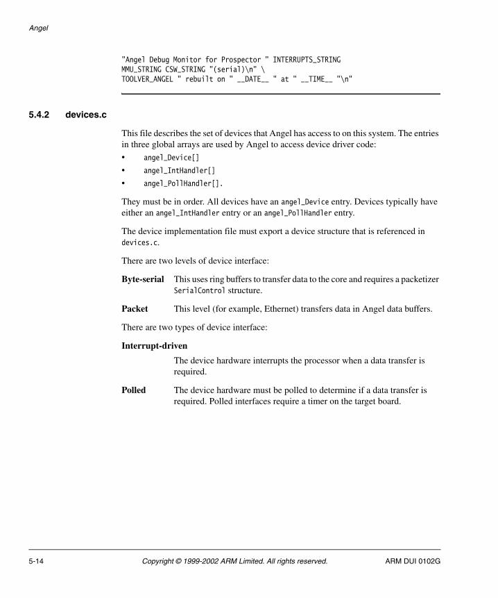
Angel
"Angel Debug Monitor for Prospector " INTERRUPTS_STRINGMMU_STRING CSW_STRING "(serial)\n" \TOOLVER_ANGEL " rebuilt on " __DATE__ " at " __TIME__ "\n"
5.4.2 devices.c
This file describes the set of devices that Angel has access to on this system. The entries in three global arrays are used by Angel to access device driver code:
• angel_Device[]
• angel_IntHandler[]
• angel_PollHandler[].
They must be in order. All devices have an angel_Device entry. Devices typically have either an angel_IntHandler entry or an angel_PollHandler entry.
The device implementation file must export a device structure that is referenced in devices.c.
There are two levels of device interface:
Byte-serial This uses ring buffers to transfer data to the core and requires a packetizer SerialControl structure.
Packet This level (for example, Ethernet) transfers data in Angel data buffers.
There are two types of device interface:
Interrupt-driven
The device hardware interrupts the processor when a data transfer is required.
Polled The device hardware must be polled to determine if a data transfer is required. Polled interfaces require a timer on the target board.
5-14 Copyright © 1999-2002 ARM Limited. All rights reserved. ARM DUI 0102G

Angel
Example 5-4 describes the system as having a serial device and, optionally, an ethernet and debug communications channel.
Example 5-4 Using device.c (1)
const struct angel_DeviceEntry *const angel_Device[DI_NUM_DEVICES] ={ &angel_AMBAUARTSerial[0], #if (AMBAUART_NUM_PORTS > 1) &angel_AMBAUARTSerial[1], #elif DEBUG && LOGTERM_DEBUGGING &angel_NullDevice, #endif
#if ETHERNET_SUPPORTED &angel_EthernetDevice, #endif
#if DCC_SUPPORTED &angel_DccDevice, #endif};
Example 5-5 describes the set of interrupt handlers that this Angel uses. Angel_TimerIntHandler is a timer interrupt for example.
Example 5-5 Using device.c (2)
/*The interrupt handler table - one entry per handler.* DE_NUM_INT_HANDLERS must be set in devconf.h to the number of* entries in this table.*/ #if (DE_NUM_INT_HANDLERS > 0)const struct angel_IntHandlerEntry angel_IntHandler[DE_NUM_INT_HANDLERS] ={ { angel_AMBAUARTIntHandler, DI_AMBAUART_A }
#if (AMBAUART_NUM_PORTS > 1) ,{ angel_AMBAUARTIntHandler, DI_AMBAUART_B } #elif DEBUG && LOGTERM_DEBUGGING ,{ angel_LogtermIntHandler, DI_AMBAUART_B } #else ,{ angel_NodevIntHandler, 0} #endif
#if TIMER_SUPPORTED
ARM DUI 0102G Copyright © 1999-2002 ARM Limited. All rights reserved. 5-15
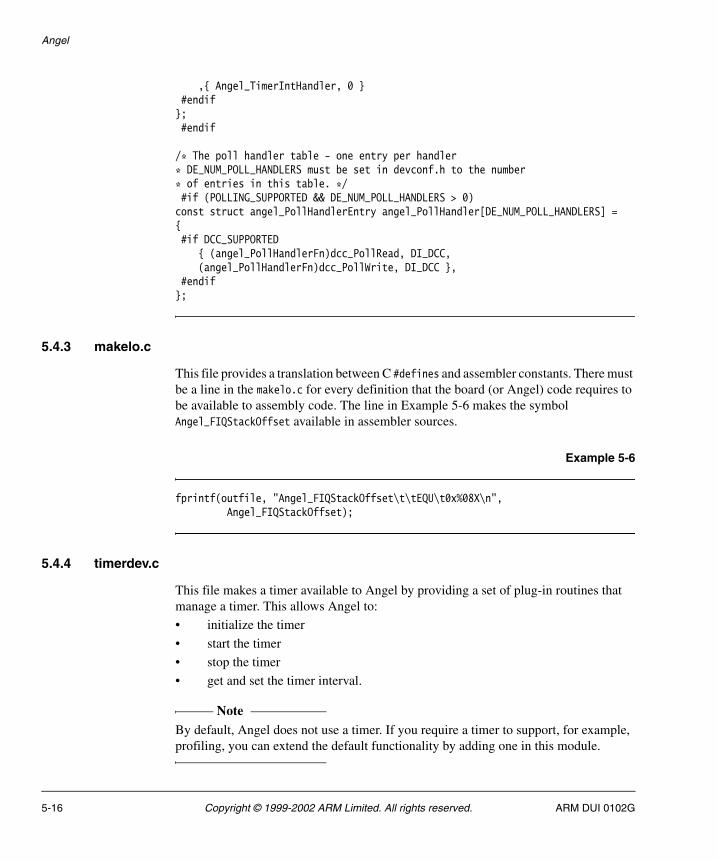
Angel
,{ Angel_TimerIntHandler, 0 } #endif}; #endif
/* The poll handler table - one entry per handler* DE_NUM_POLL_HANDLERS must be set in devconf.h to the number* of entries in this table. */ #if (POLLING_SUPPORTED && DE_NUM_POLL_HANDLERS > 0)const struct angel_PollHandlerEntry angel_PollHandler[DE_NUM_POLL_HANDLERS] ={ #if DCC_SUPPORTED { (angel_PollHandlerFn)dcc_PollRead, DI_DCC, (angel_PollHandlerFn)dcc_PollWrite, DI_DCC }, #endif};
5.4.3 makelo.c
This file provides a translation between C #defines and assembler constants. There must be a line in the makelo.c for every definition that the board (or Angel) code requires to be available to assembly code. The line in Example 5-6 makes the symbol Angel_FIQStackOffset available in assembler sources.
Example 5-6
fprintf(outfile, "Angel_FIQStackOffset\t\tEQU\t0x%08X\n", Angel_FIQStackOffset);
5.4.4 timerdev.c
This file makes a timer available to Angel by providing a set of plug-in routines that manage a timer. This allows Angel to:
• initialize the timer
• start the timer
• stop the timer
• get and set the timer interval.
Note By default, Angel does not use a timer. If you require a timer to support, for example, profiling, you can extend the default functionality by adding one in this module.
5-16 Copyright © 1999-2002 ARM Limited. All rights reserved. ARM DUI 0102G
Angel
5.4.5 serial.c
This file contains the serial device driver for this particular platform. For µHAL-based Angel, this usually reuses the board-specific definitions from µHAL (for example, the bits in the individual UART registers) to implement the serial device functions of the Angel.
5.4.6 target.s
Angel must have various macros defined within target.s. These are used at system startup by startrom.s. These macros are:
UNMAPROM This macro is called by the startrom.s ROM initialization code. It is called in systems that use ROM remapping to ensure that the ROM image is at 0 at reset. After the system has been initialized, this macro is called to switch the ROM to its physical address and RAM at 0. The actual mechanism for performing the remap varies from board to board. For more details, refer to the documentation for your hardware.
STARTUPCODE
This macro is called from startrom.s for target-specific startup. It is likely to include memory sizing, initialization of memory controllers, and interrupt controller reset.
INITMMU This macro initializes the MMU (or MPU).
Note Take care with this macro because the location of the page table is
important to the operation of the macro and must be given correctly. There is also a setup issue if the operation of the system is big-endian as the MMU is responsible for the byte order of the core and must be set up early to allow the correct operation of the code.
INITTIMER This macro allows initialization of any timers required by the application. It is called after the interrupts are disabled and the system is set in Supervisor mode.
GETSOURCE This macro is called by suppasm.s routines (the general Angel support routines). It defines the Angel interrupts used and offers a small amount of prioritization to ensure that the communications source has priority for Angel operation. The routine places the C-defined source value (defined in devconf.h). These values are used by the interrupt handler for a jump table holding the individual Angel Interrupt source handler function pointers.
ARM DUI 0102G Copyright © 1999-2002 ARM Limited. All rights reserved. 5-17
Angel
CACHE_IBR This macro is called from suppasm.s support code to set an Instruction Barrier Range. This is required on systems with processors that have a Harvard cache.
None of these macros are used within µHAL and so must be written for Angel. However, existing µHAL macros can be reused. For example, the Integrator STARTUPCODE macro reuses the µHAL INIT_RAM and DISABLE_INTS macros.
5.4.7 devconf.h
This file is the main configuration file for the target image. It sets up the Angel resources for the specific target and shows the hardware available for Angel usage including:
• available memory map
• interrupt operation
• peripherals
• devices.
This file contains macros that define:
• feature set and device drivers enabled
• debug enable and method
• interrupt masks and ID numbers
• stack sizes
• start from ROM or RAM selection
• system clock speed
• device ID codes
• ring buffer sizes.
Caution DCC and CACHE support are processor-dependent. Declaration of either of these support calls enables routines that only work for specific processor options. If the processor options do not match your board, Angel halts.
The DEBUG_METHOD is only applicable when the DEBUG compiler option is set in the makefile. It defines the channel to be used to pass the debug messages.
The definitions from the Integrator version are shown in Example 5-7 on page 5-19.
5-18 Copyright © 1999-2002 ARM Limited. All rights reserved. ARM DUI 0102G

Angel
Example 5-7 Angel definitions
/* Choose the method for debug output here. Options supported for PID are:* panicblk panic string written to RAM* logserial via Serial port at 115200 baud* logterm as logserial, but interactive. */ #if DEBUG #if MINIMAL_ANGEL #define DEBUG_METHOD panicblk #else #define DEBUG_METHOD logterm #endif #endif
Interrupt operation is selectable for Angel allowing the use of IRQ, FIQ, or both interrupts as sources for the ADP channel communications. µHAL-based Angel currently only supports FIQ. If the FIQ is chosen as the source for Angel communications channel, the FIQ safety-level descriptor defines the operation of the FIQ with regard to use of the Angel serializer. The recommended default setting is to ensure that FIQs use the serializer and lock mechanisms. The other options are shown in serlock.h in the generic code section.
The memory map must be defined to allow the debugger to control illegal read/writes using the PERMITTED checks. These must reflect the permitted access to the system memory architecture. For Integrator, the PERMITTED macros are:
/* These macros are used by debugger-originated memory reads/writes to check if the write is valid. */ #define READ_PERMITTED(__addr__) (1) #define WRITE_PERMITTED(__addr__) (1)
Note You must take care with systems that have access to the full 4GB of memory, as the highest section of memory must equate to 0xFFFFFFFF when the base and size are defined as a sum, and it might wrap around to 0.
For example, if there is memory-mapped input/output at 0xFFD00000 the definition must be:
#define IOBase (0xFFD00000) #define IOSize (0x002FFFFF) #define IOTop (IOBase + IOSize)
and not:
ARM DUI 0102G Copyright © 1999-2002 ARM Limited. All rights reserved. 5-19
Angel
#define IOBase (0xFFD00000) #define IOSize (0x00300000) #define IOTop (IOBase + IOSize)
By default, Angel checks for the highest available memory location from the default location. This is useful for systems, such as Integrator, where memory can be added into the DRAM slots but still must be accessed by Angel. It allows the stacks and heap more space by relocating to the top of memory. It allows a single Angel to be used across a common product range with similar memory maps but different memory sizes.
The stacks must be defined for all processor modes that are used by Angel. These always include User, SVC, UNDEF, and the appropriate mode for the chosen Interrupt source. The location of the stacks can be fixed, or can be set to the top of memory once this has been defined by the memory sizing function. All other Angel-defined memory spaces (fusion stack heaps, profile work area, and application stacks) can be defined to sit relative to the stacks, or they can be given fixed locations. The default for the application heap space is above the run-time Angel code and the available space is to the lowest limit of the stacks. The definition for Integrator is shown in Example 5-8.
Example 5-8 Integrator definitions
/* The following are the sizes of the various Angel stacks */ #define Angel_UNDStackSize 0x0100
#define Angel_ABTStackSize 0x0100
#define Angel_AngelStackSize (POOLSIZE *Angel_AngelStackFreeSpace)
#define Angel_SVCStackSize 0x0800
Note Angel stack space is different from the application stack space to allow Angel to debug code that has corrupt or missing stacks.
The download agent area must be a spare area of RAM that can be used for testing. The download agent usually executes from the load agent address and copies itself over the resident RAM Angel image (that is, it executes in the same way as the ROM-based image).
The available devices must be defined in the structure DeviceIdent. The definition for Integrator is shown in Example 5-9 on page 5-21.
5-20 Copyright © 1999-2002 ARM Limited. All rights reserved. ARM DUI 0102G

Angel
Example 5-9 DeviceIdent
typedef enum DeviceIdent{ DI_AMBAUART_A, #if (AMBAUART_NUM_PORTS > 1) || (DEBUG && LOGTERM_DEBUGGING) DI_AMBAUART_B, #endif #if ETHERNET_SUPPORTED DI_ETHER, #endif #if DCC_SUPPORTED DI_DCC, #endif DI_NUM_DEVICES}DeviceIdent;
You must ensure that the order in this structure is the same as that defined in the array in devices.c, as this allows access to the register base of the specified ports in the defined order. This is also true for the interrupt handler structure. Because this is the basis for the jump table in suppasm.s, the order and number must be the same as defined in devices.s. The labels must also be placed in makelo.c to ensure that they are available for suppasm.s.
ARM DUI 0102G Copyright © 1999-2002 ARM Limited. All rights reserved. 5-21

Angel
5.5 Device drivers
These files are the main area of the porting operation. The files are application-dependent. The control of the device is carried out through function pointers defined in devclnt.h, devdriv.h and serring.h.
The main controlling functions are:
• angel_DeviceControlFn() on page 5-24
• Transmit control (ControlTx) on page 5-24
• Receive control (ControlRx) on page 5-25
• Transmit kickstart (KickStart) on page 5-25
• Interrupt handler on page 5-25.
5.5.1 The SerialControl structure
The individual control functions are located by the contents of a SerialControl structure. Example 5-10 shows the definition of the control functions and the SerialControl structure from serring.h.
Example 5-10 serring.h definitions
/* function prototypes */typedef void (*ControlTx_Fn)(DeviceID devid);typedef void (*ControlRx_Fn)(DeviceID devid);typedef DevError (*Control_Fn)(DeviceID devid, DeviceControl op, void *arg);typedef void (*KickStart_Fn)(DeviceID devid);typedef void (*Processor_Fn)(void *args);
/* collected glue for interface between high- and low-level device drivers */typedef struct SerialControl { RxTxState *const rx_tx_state; /* can be NULL */ RawState *const raw_state; /* can be NULL --> look for ETX */ Processor_Fn tx_processing; /* how to fill/process tx ring */ Processor_Fn rx_processing; /* how to read/process rx ring */ unsigned int port; /* device-specific ID */ RingBuffer *const tx_ring; /* tx ring buffer */ RingBuffer *const rx_ring; /* rx ring buffer */ ControlTx_Fn control_tx; /* how to control tx IRQs, etc. */ ControlRx_Fn control_rx; /* how to control rx IRQs, etc. */ Control_Fn control; /* device control function */ KickStart_Fn kick_start; /* kick-start function for tx */} SerialControl;
5-22 Copyright © 1999-2002 ARM Limited. All rights reserved. ARM DUI 0102G

Angel
The actual functions used to satisfy the control functions depend on the type and number of I/O devices. The code in Example 5-11 is for the AMBA UART located on the Integrator.
Example 5-11 AMBA UART code
/* The control functions and interface */static const SerialControl ambauart_Ctrl[AMBAUART_NUM_PORTS] ={ { #if (RAW_AMBAUART_A == 0) &ambauart_rx_tx_state[AMBAUART_IDENT_A], NULL, serpkt_int_tx_processing, serpkt_int_rx_processing, #else NULL, &ambauart_raw_state[AMBAUART_IDENT_A], serraw_int_tx_processing, serraw_int_rx_processing, #endif AMBAUART_IDENT_A, &ambauart_tx_ring[AMBAUART_IDENT_A], &ambauart_rx_ring[AMBAUART_IDENT_A], ambauart_ControlTx, ambauart_ControlRx, ambauart_Control, ambauart_KickStartFn } #if AMBAUART_NUM_PORTS > 1 ,{ #if (RAW_AMBAUART_B == 0) &ambauart_rx_tx_state[AMBAUART_IDENT_B], NULL, &packet_state[AMBAUART_IDENT_B], serpkt_int_tx_processing, serpkt_int_rx_processing, #else NULL, &ambauart_raw_state[AMBAUART_IDENT_B], NULL, serraw_int_tx_processing, serraw_int_rx_processing, #endif AMBAUART_IDENT_B, &ambauart_tx_ring[AMBAUART_IDENT_B], &ambauart_rx_ring[AMBAUART_IDENT_B], ambauart_ControlTx, ambauart_ControlRx, ambauart_Control, ambauart_KickStartFn } #endif};
ARM DUI 0102G Copyright © 1999-2002 ARM Limited. All rights reserved. 5-23
Angel
5.5.2 angel_DeviceControlFn()
This controls the device by passing in a set of standard control values that are defined in devices.h in the main directory.
Syntax
DevError angel_DeviceControl(DeviceId devID, DeviceControl op, void *arg)
where:
devID Is the index of the device to control.
op Is the operation to perform.
arg Is a parameter depending on the operation.
Examples of the values for devID are:
DC_INIT Specific device initialization at the start of a session.
DC_RESET Device reinitialization to set the device into a known operational state ready to accept input from the host at the default setup.
DC_RECEIVE_MODE
Receive Mode Select. Sets the device into and out of receive mode.
DC_SET_PARAMS
Set device operational parameters. Sets the device parameters at initialization. This is also used if the host must renegotiate the parameters, for example in the instance of a change of baud rate.
Return value
Returns one of the following:
DE_OKAY Control request is underway.
DE_NO_DEV No such device.
DE_BAD_OP Device does not support operation.
5.5.3 Transmit control (ControlTx)
When in operation, Angel defaults to the receive active state. This allows quick response to host messages. This function controls the transmit path of the serial driver, switching it on or off depending on the flag status set up in the calling routine.
5-24 Copyright © 1999-2002 ARM Limited. All rights reserved. ARM DUI 0102G
Angel
5.5.4 Receive control (ControlRx)
This function is similar to Transmit control (ControlTx) on page 5-24. It controls the receive channel.
5.5.5 Transmit kickstart (KickStart)
As Angel generally operates in receive active mode, transmission must be initiated by this function. The ADP construction code sets up the bytes to be transmitted for a message to the host in a transmit buffer. It then calls the kick_start() function to initiate the transfer. This routine takes the first character from the transmit buffer and passes it to the serial Tx register. This causes a Tx interrupt from which the interrupt handler passes the remainder of the buffer as each character is transmitted.
5.5.6 Interrupt handler
The interrupt handlers are generic for each peripheral. In the case of the Integrator boards, the interrupt handler controls interrupts from each serial driver Tx and Rx as well as the parallel reads.
The interrupt handler determines the source of the interrupt and performs the appropriate action depending on the source:
Tx Pass bytes from the internal Tx buffer to the serial Tx FIFO, if there is space in the FIFO.
Rx Pass the byte received at the Rx FIFO into the internal Rx buffer, ready for Angel to unpack the message when the transfer is complete.
Parallel The parallel port is polled to pass the data received into the memory location requested.
All the above operations are serialized by Angel to ensure that they are not interrupted by any other operations. Interrupts are disabled from the start of the interrupt handler routine until the serializer function is called.
Other system drivers (Ethernet/DCC for example) might not require the full operation functions and instead require only a pure Rx/Tx control.
ARM DUI 0102G Copyright © 1999-2002 ARM Limited. All rights reserved. 5-25
Angel
5.6 Developing applications with Angel
This section gives useful information on how to develop applications under Angel:
• Planning your development project
• Programming restrictions on page 5-27
• Using Angel with an RTOS on page 5-27
• Using Supervisor mode on page 5-28
• Chaining exception handlers on page 5-29
• Linking Angel C library functions on page 5-30
• Using assertions when debugging on page 5-30
• Setting breakpoints on page 5-30
• Changing from little-endian to big-endian Angel on page 5-30
• Application communications on page 5-31.
5.6.1 Planning your development project
Before you begin your development project you must make basic decisions about such things as:
• the ATPCS variant to be used for your project
• whether or not ARM/Thumb interworking is required
• the endianness of your target system.
Applications built with µHAL handle these issues by default.
Refer to the appropriate documentation supplied with ADS for more information on interworking ARM and Thumb code, and specifying ATPCS options.
In addition, you must consider:
• Whether or not you require C library support in your final application. You must decide how you implement C library I/O functions if they are required, because the Angel semihosting SWI mechanism will not be available. Refer to Linking Angel C library functions on page 5-30 for more information.
• Whether or not the image is built with debug enabled. You must be aware of the small size overhead when using debuggable images as production code.
• Communications requirements. You must write your own device drivers for your production hardware.
• Memory requirements. You must ensure that your hardware has sufficient memory to hold both Angel and your program images.
5-26 Copyright © 1999-2002 ARM Limited. All rights reserved. ARM DUI 0102G

Angel
5.6.2 Programming restrictions
Angel resource requirements introduce a number of restrictions on application development under Angel:
• Angel requires control of its own Supervisor stack. If you are using an RTOS you must ensure that it does not change processor state while Angel is running. Refer to Using Angel with an RTOS for more information.
• You must not use ARM SWI 0x123456 or Thumb SWI 0xAB in your SWI handling code. These SWIs are used by Angel to support C library semihosting requests.
• If you are using SWIs in your application, and using Multi-ICE for debugging, you must usually set a breakpoint on the SWI handler routine, where you know it is a SWI, rather than at the SWI vector itself.
• If you are using SWIs in your application you must restore registers to the state that they were when you entered the SWI.
• If you want to use the Undefined Instruction exception for any reason you must remember that Angel uses this to handle breakpoints and the exception must be chained.
5.6.3 Using Angel with an RTOS
From the application perspective Angel is single-threaded, modified by the ability to use interrupts provided the interrupt is not context switching. External functions must not change processor modes through interrupts. This means that running Angel and an RTOS together is difficult, and is not recommended unless you are prepared for a significant amount of development effort.
If you are using an RTOS you will have difficulties with contention between the RTOS and Angel when handling interrupts. Angel requires control over its own stacks, task scheduling, and the processor mode when processing an IRQ or FIQ.
An RTOS task scheduler must not perform context switches while Angel is running. Context switches must be disabled until Angel has finished processing.
For example:
1. An RTOS installs an ISR to perform interrupt-driven context switches.
2. The ISR is enabled when Angel is active (for example, handling a debug request).
3. An interrupt occurs when Angel is running code.
4. The ISR switches the Angel context, not the RTOS context.
That is, the ISR puts values in processor registers that relate to the application, not to Angel, and it is very likely that Angel will crash.
ARM DUI 0102G Copyright © 1999-2002 ARM Limited. All rights reserved. 5-27

Angel
There are two ways to avoid this situation:
• Detect ISR calls that occur when Angel is active, and do not task switch. The ISR can run, provided the registers for the other mode are not touched. For example, timers can be updated.
• Disable either IRQ or FIQ interrupts, the one Angel is not using, while Angel is active. This is not easy to do.
In summary, the normal process for handling an IRQ under an RTOS is:
1. IRQ exception generated.
2. Do any urgent processing.
3. Enter the IRQ handler.
4. Process the IRQ and issue an event to the RTOS if required.
5. Exit by way of the RTOS to switch tasks if a higher priority task is ready to run.
Under Angel this procedure must be modified to:
1. IRQ exception generated.
2. Do any urgent processing.
3. Check whether Angel is active:
a. If Angel is active then the CPU context must be restored on return, so scheduling cannot be performed, although for example a counter can be updated. Exit by restoring the pc to the interrupted address.
b. If Angel is not active, process as normal, exiting by way of the scheduler if required.
Note See Chapter 4 Operating Systems and µHAL for an example of RTOS scheduling.
5.6.4 Using Supervisor mode
If you want your application to execute in Supervisor mode at any time, you must set up your own Supervisor stack. If you call a SWI while in Supervisor mode, Angel uses four words of your Supervisor stack when entering the SWI. After entering the SWI Angel uses its own Supervisor stack, not yours.
5-28 Copyright © 1999-2002 ARM Limited. All rights reserved. ARM DUI 0102G

Angel
This means that, if you set up your own Supervisor mode stack and call a SWI, the Supervisor stack pointer register (sp_SVC) must point to four words of a full descending stack in order to provide sufficient stack space for Angel to enter the SWI.
5.6.5 Chaining exception handlers
Angel provides exception handlers for the Undefined, SWI, IRQ/FIQ, Data Abort, and Prefetch Abort exceptions. If you are working with exceptions, you must ensure that any exception handler that you add is chained correctly with the Angel exception handlers. Refer to the description of processor exceptions in the documentation supplied with ADS for more information.
If you are chaining an interrupt handler and you know that the next handler in the chain is the Angel interrupt handler, you can use the Angel interrupt table rather than the processor vector table. You do not have to modify the processor vector table. The Angel interrupt table is easier to manipulate because it contains the 32-bit address of the handler. The processor vector table is limited to 24-bit addresses.
Note If your application chains exception handlers (including ISRs) and you kill the application, Angel must be reset with a hardware reset. This ensures that the vectors are set up correctly when the application is restarted.
The consequences of not passing an exception on to Angel from your exception handler depend on the type of exception, as follows:
Undefined You are not able to single step or set breakpoints from the debugger.
SWI If you do not implement the EnterSVC SWI, Angel does not work. If you do not implement any of the other SWIs you cannot use semihosting.
Prefetch Abort
The exception is not trapped in the debugger.
Data Abort The exception will not be trapped in the debugger. If a Data Abort occurs during a debugger-originated memory read or write, the operation might not proceed correctly, depending on the action of the handler.
IRQ This depends on how Angel is configured. Angel does not work if it is configured to use IRQ as its interrupt source.
FIQ This depends on how Angel is configured. Angel does not work if it is configured to use FIQ as its interrupt source.
ARM DUI 0102G Copyright © 1999-2002 ARM Limited. All rights reserved. 5-29

Angel
5.6.6 Linking Angel C library functions
The C libraries provided with the ARM tools use SWIs to implement semihosting requests. For more information on using libraries, refer to the compiler and library documentation supplied with ADS. You have two options for using ARM C library functionality:
• Use the ARM C library semihosting functions for early prototyping and redefine individual library I/O functions with your own C functions targeted at your hardware and operating system environment.
• Support SWIs in your own application or operating system and use the ARM C libraries as provided.
5.6.7 Using assertions when debugging
To speed up debugging, Angel includes runtime assertion code that checks that the state of Angel is as expected. The Angel code defines the ASSERT_ENABLED option to enable and disable assertions.
If you use assertions in your code you must wrap them in the protection of ASSERT_ENABLED macros so that you can disable them in the final version if required.
#if ASSERT_ENABLED... #endif
Angel uses such assertions wherever possible. For example, assertions are made when it is assumed that a stack is empty, or that there are no items in a queue. You must use assertions whenever possible when writing device drivers. The ASSERT macro is available if the code is a simple condition check (variable = value).
5.6.8 Setting breakpoints
Angel can set breakpoints in RAM only. You cannot set breakpoints in ROM or Flash.
In addition, you must be careful when using single step or breakpoints on the UNDEF, IRQ, FIQ, or SWI vectors. Do not single step or set breakpoints on interrupt service routines on the code path used to enter or exit Angel.
5.6.9 Changing from little-endian to big-endian Angel
Changing memory byte order is dependent on the development board you are using. Refer to the documentation that was supplied with the board.
5-30 Copyright © 1999-2002 ARM Limited. All rights reserved. ARM DUI 0102G

Angel
5.6.10 Application communications
Angel requires use of at least one device driver for its own communications requirements. If you are using Angel on a board with more than one serial port, such as Integrator, you can either:
• use Angel on one serial port and your own device on the other
• use a customized version of Angel that requires no serial port, and use either or both of the serial ports for your application.
The Angel port for Integrator provides examples of raw serial drivers. Refer to the Angel source code for details of how these are implemented. If you want to use Angel with your own hardware you must write your own device drivers.
Angel serial drivers
Figure 5-1 gives an overview of the Angel serial device architecture.
Figure 5-1 Serial device architecture
������
�����
������
�������
������
�����������
����������
���������� ���������
����������������
�����������
����������
����� � ����
��������
������� ��
�!� �����
"�������
�!� ����������������
����������������������
�����������
����������
�#����
�#����
�!� ����������
ARM DUI 0102G Copyright © 1999-2002 ARM Limited. All rights reserved. 5-31
Angel
Using the Debug Communication Channel
You can use cin and cout in armsd, the channel viewer interface, or the ARM debugger GUI to access the DCC from the host. You can use the DCC channel to send ARM DCC instructions to the processor. No other extra channels are supported.
5-32 Copyright © 1999-2002 ARM Limited. All rights reserved. ARM DUI 0102G
Angel
5.7 Angel in operation
This section briefly explains Angel operations you must understand before porting Angel to your own hardware. It contains the following:
• Initialization
• Waiting for debug communications on page 5-34
• Angel debugger functions on page 5-35
• Angel task management on page 5-37
• Context switching on page 5-41
• Example of Angel processing: a simple IRQ on page 5-44.
5.7.1 Initialization
The initialization of the code environment and system is almost identical, whether the code is to initialize the debugger or to launch an application. The initialization sequence is:
1. The processor is switched from the current privileged mode to Supervisor mode with interrupts disabled. Angel checks for the presence of an MMU. If an MMU is present it can be initialized after switching to Supervisor mode.
2. Angel sets the code execution and vector location, depending on the compilation addresses generated by the values of ROADDR and RWADDR.
3. Code and data segments for Angel are copied to their execution addresses.
4. If the application is to be executed then the runtime system setup code and the application itself are copied to their execution addresses. If the system has ROM at address 0 and the code is to be run from ROM, only the Data and Zero Initialization areas are copied.
5. The stack pointers are set up for each processor mode that Angel operates in. Angel maintains control of its own stacks separately from any application stacks. You can configure the location of Angel stacks.
6. Target-specific functions such as MMU or Profiling Timer are initialized if they are included in the system.
7. The Angel serializer is set up. Refer to the Angel task management on page 5-37 for more information on the Angel serializer.
8. The processor is switched to User mode and program execution is passed to the high-level initialization code for the C library and Angel C functions.
When initialization is complete, program execution is directed to the __main entry point.
ARM DUI 0102G Copyright © 1999-2002 ARM Limited. All rights reserved. 5-33
Angel
9. At this point, the initialization sequence is executed:
a. The communications channels are initialized for the Angel Debug Protocol (ADP).
b. Any raw data channels installed for the application are set up if you are using extra channels. The application can set this up itself. Refer to the Angel source code for details.
c. Angel transmits its boot message through the boot task and waits for communication from the debugger.
5.7.2 Waiting for debug communications
After initialization, Angel enters the idle loop and, if polling is enabled, it continually calls the device polling function. All current boards use interrupts instead of looping in the poll routine. This ensures that any polled communications device is serviced regularly. When input is detected, it is placed into a buffer and decoded into packet form to determine the operation that has been requested. If an acknowledgment or reply is required, it is constructed in an output buffer ready for transmission.
All Angel operations are controlled by Angel task management. Refer to Angel task management on page 5-37 and Example of Angel processing: a simple IRQ on page 5-44 for more information on Angel task management.
5-34 Copyright © 1999-2002 ARM Limited. All rights reserved. ARM DUI 0102G
Angel
5.7.3 Angel debugger functions
This section gives a summary of how Angel performs the basic debugger functions:
• reporting memory and processor status
• downloading a program image
• setting breakpoints.
Reporting processor and memory status
Angel reports the contents of memory and the processor registers as follows:
Memory The memory address being examined is passed to a function that copies the memory as a byte stream to the transmit buffer. The data is transmitted to the host as an ADP packet.
Registers Processor registers are saved into a data block when Angel takes control of the target (usually at an exception entry point). When processor status is requested, a subset of the data block is placed in an ADP packet and transmitted to the host.
When Angel receives a request to change the contents of a register, it changes the value in the data block. The data block is stored back to the processor registers when Angel releases control of the target and execution returns to the target application.
Download
When downloading a program image to your board, the debugger sends a sequence of ADP memory write messages to Angel. Angel writes the image to the specified memory location.
Memory write messages are special because they can be longer than other ADP messages. If you are porting Angel to your own hardware your device driver must be able to handle messages that are longer than 256 bytes. The actual length of memory write messages is determined by your Angel port. Message length is defined in devconf.h with:
#define BUFFERLONGSIZE
ARM DUI 0102G Copyright © 1999-2002 ARM Limited. All rights reserved. 5-35
Angel
Setting breakpoints
Angel uses three Undefined Instructions to set breakpoints. The instruction used depends on:
• the endianness of the target system
• the processor state (ARM or Thumb):
— In ARM state, Angel recognizes the following words as breakpoints:
0xE7FDDEFE for little-endian systems
0xE7FFDEFE for big-endian systems.
— In Thumb state, Angel recognizes 0xDEFE as a breakpoint.
Note These are not the same as the breakpoint instructions used by Multi-ICE.
These instructions are used for normal, user interrupt, and vector hit breakpoints. In all cases, no arguments are passed in registers. The breakpoint address itself is where the breakpoint occurs.
When you set a breakpoint, Angel:
• stores the original instruction to ensure that it is returned if the area containing it is examined
• replaces the instruction with the appropriate Undefined Instruction.
The original instruction is restored when the breakpoint is removed, or when a request to read the memory that contains the instruction is made in the debugger. When you step through a breakpoint, Angel replaces the saved instruction and executes it.
Note Angel can set breakpoints only on RAM locations.
When Angel detects an Undefined Instruction it:
1. Examines the instruction by executing an:
• LDR instruction from lr – 4, if in ARM state
• LDR instruction from lr – 2, if in Thumb state.
2. If the instruction is the predefined breakpoint word for the current processor state and endianness, Angel:
a. Halts execution of the application.
b. Transmits a message to the host to indicate the breakpoint status.
c. Executes a tight poll loop and waits for a reply from the host.
5-36 Copyright © 1999-2002 ARM Limited. All rights reserved. ARM DUI 0102G

Angel
If the instruction is not the predefined breakpoint word, Angel:
a. Reports it to the debugger as an undefined instruction.
b. Executes a tight poll loop and waits for a reply from the host.
ARM breakpoints are detected in Thumb state. When an ARM breakpoint is executed in Thumb state, the Undefined Instruction vector is taken whether executing the instruction in the top or bottom half of the word. In both cases these correspond to a Thumb Undefined Instruction and result in a branch to the Thumb Undefined Instruction handler.
Note Thumb breakpoints are not detected in ARM state.
5.7.4 Angel task management
All Angel operations are controlled by Angel task management that:
• assigns task priorities and schedules tasks accordingly
• controls the Angel environment processor mode.
Angel task management requires control of the processor mode. This can impose restrictions on using Angel with an RTOS. Refer to Using Angel with an RTOS on page 5-27 for more information.
Task priorities
Angel assigns task priorities to tasks under its control. Angel ensures that its tasks have priority over any application task. Angel takes control of the execution environment by installing exception handlers at system initialization. The exception handlers enable Angel to check for commands from the debugger and process application semihosting requests.
Angel does not function correctly if your application or RTOS interferes with the execution of the interrupt, SWI, or Data Abort exception handlers. Refer to Chaining exception handlers on page 5-29 for more information.
When an exception occurs, Angel either processes it completely as part of the exception handler processing, or calls Angel_SerialiseTask() to schedule a task. For example:
• When a SWI occurs, Angel determines whether the SWI is a simple SWI that can be processed immediately, such as the EnterSVC SWI, or a complex SWI that requires access to the host communication system, and therefore to the serializer.
ARM DUI 0102G Copyright © 1999-2002 ARM Limited. All rights reserved. 5-37

Angel
• When an IRQ occurs, Angel determines whether or not the IRQ signals the receipt of a complete ADP packet. If it does, Angel task management is called to control the packet decode operation. Refer to Example of Angel processing: a simple IRQ on page 5-44 for more information. Other Angel ports can make other choices for IRQ processing, provided the relevant task is eventually run.
The task management code maintains two values that relate to priority:
Task type The task type indicates type of task being performed. For example, the application task is of type TP_Application, and Angel tasks are usually TP_AngelCallback. The task type labels a task for the lifetime of the task.
Task priority The task priority is initially derived from the task type, but is independent afterwards. Actual priority is indicated in:
• the value of a variable in the task structure
• the relative position of the task structure in the task queue.
The task priority of the application task changes when an application SWI is processed, to ensure correct interleaving of processing.
Table 5-1 shows the relative task priorities used by Angel.
Angel task management is implemented through the following top-level functions:
• Angel_SerialiseTask()
• Angel_NewTask()
• Angel_QueueCallback()
• Angel_BlockApplication()
• Angel_NextTask()
Table 5-1 Task priorities
Priority Task Description
Highest AngelWantLock High priority callback.
- AngelCallBack Callbacks for Angel.
- ApplCallBack Callbacks for the user application.
- Application The user application.
- AngelInit Boot task. Emits boot message on reset and then exits.
Lowest IdleLoop Waiting for task.
5-38 Copyright © 1999-2002 ARM Limited. All rights reserved. ARM DUI 0102G

Angel
• Angel_Yield()
• Angel_Wait()
• Angel_Signal()
• Angel_TaskID().
Some of these functions call other Angel functions not documented here. The functions are described in brief below. For full implementation details, refer to the source code in serlock.h, serlock.c, and serlasm.s.
Angel_SerialiseTask
In most cases this function is the entrance function to Angel task management. The only tasks that are not a result of a call to Angel_SerialiseTask() are the boot task, the idle task, and the application. These are all created at startup. When an exception occurs, Angel_SerialiseTask() cleans up the exception handler context and calls Angel_NewTask() to create a new high priority task. It must be entered in a privileged mode.
Angel_NewTask
Angel_NewTask() is the core task creation function. It is called by Angel_SerialiseTask() to create task contexts.
Angel_QueueCallback
This function:
• queues a packet notification callback task
• specifies the priority of the callback
• specifies up to four arguments to the callback.
The callback executes when all tasks of a higher priority have completed. Table 5-1 on page 5-38 shows relative task priorities.
Angel_BlockApplication
This function is called to allow or disallow execution of the application task. The application task remains queued, but is not executed. If Angel is processing an application SWI when Angel_BlockApplication() is called, the block might be delayed until just before the SWI returns.
ARM DUI 0102G Copyright © 1999-2002 ARM Limited. All rights reserved. 5-39
Angel
Angel_NextTask
This is not a function, in that it is not called directly. Angel_NextTask() is executed when a task returns from its main function. This is done by setting the link register to point to Angel_NextTask() on task entry.
The Angel_NextTask() routine:
• enters Supervisor mode
• disables interrupts
• calls Angel_SelectNextTask() to select the first task in the task queue that has not been blocked and run it.
Angel_Yield
This is a yield function for polled devices. It can be called:
• by the application
• by Angel while waiting for communications on a polled device
• within processor-bound loops such as the idle loop.
Angel_Yield() uses the same serialization mechanism as IRQ interrupts. Like an IRQ, it can be called from either User or Supervisor mode and returns cleanly to either mode. If it is called from User mode it calls the EnterSVC SWI to enter Supervisor mode, and then disables interrupts.
Angel_Wait
Angel_Wait() works in conjunction with Angel_Signal() to enable a task to wait for a predetermined event or events to occur before continuing execution. When Angel_Wait() is called, the task is blocked unless the predetermined event has already been signalled with Angel_Signal().
Angel_Wait() is called with an event mask. The event mask denotes events that result in the task continuing execution. If more than one bit is set, any one of the events corresponding to those bits unblocks the task. The task remains blocked until another task calls Angel_Signal() with one or more of the event mask bits set. The meaning of the event mask must be agreed beforehand by the routines.
If Angel_Wait() is called with a zero event mask, execution continues normally.
5-40 Copyright © 1999-2002 ARM Limited. All rights reserved. ARM DUI 0102G
Angel
Angel_Signal
Angel_Signal() works in conjunction with Angel_Wait(). This function sends an event to a task that is now waiting for it, or will wait for it in the future:
• If the task is blocked, Angel_Signal() assumes that the task is waiting and subtracts the new signals from the signals the task was waiting for. The task is unblocked if the event corresponds to any of the event bits defined when the task called Angel_Wait().
• If the task is running, Angel_Signal() assumes that the task will call Angel_Wait() at a time in the future. The signals are marked in the task signalWaiting member.
Angel_Signal() takes a task ID that identifies a current task, and signals the task that the event has occurred. See the description of Angel_Wait() for more information on event bits. The task ID for the calling task is returned by the Angel_TaskID() macro. The task must write its task ID to a shared memory location if an external task is to signal it.
Angel_TaskID
This macro returns the task ID (a small integer) of the task that calls it.
Angel_TaskIDof
This macro takes a task structure pointer and returns the task ID of that task.
5.7.5 Context switching
Angel maintains context blocks for each task under its control through the life of the task, and saves the value of all current processor registers when a task switch occurs. It uses two groups of register context save areas:
• The Angel global register blocks. These are used to store the CPU registers for a task when events such as interrupt and task deschedule events occur.
• An array of available Task Queue Items (TQIs). Each allocated TQI contains the information Angel requires to correctly schedule a task, and to store the CPU registers for a task when required.
ARM DUI 0102G Copyright © 1999-2002 ARM Limited. All rights reserved. 5-41

Angel
The global register blocks: angel_GlobalRegBlock
The Angel global register blocks are used by all the exception handlers and the special functions Angel_Yield() and Angel_Wait(). Register blocks are defined as an array of seven elements. Table 5-2 shows the global register blocks.
In the case of RB_SWI and RB_Interrupted, the register blocks contain the previous task register context so that the interrupt can be handled. If the handler function calls Angel_SerialiseTask(), the global register context is saved into the current task TQI.
In the case of RB_Yield, the register block is used to temporarily store the context of the calling task, prior to entering the serializer. The serializer saves the contents of RB_Yield to the TQI entry for the current task, if required.
The Angel task queue: angel_TQ_Pool
The serializer maintains a task queue by linking together the elements of the angel_TQ_Pool array. The task queue must contain an idle task entry. Each element of the array is a TQI. A TQI contains task information such as:
• the register context for the task
• the current priority of the task
• the type of the task (for example, TP_Application)
• the task state (for example, TS_Blocked)
• the initial stack value for the task
• a pointer to the next lower-priority task.
Table 5-2 Global register blocks
Register block Description
RB_Interrupted Used by the FIQ and IRQ exception handlers.
RB_Desired Used by Angel_SerialiseTask().
RB_SWI Saved on entry to a complex SWI and restored on return to the application.
RB_Undef Saved on entry to the undefined instruction handler.
RB_Abort Saved on entry to the abort handler.
RB_Yield Used by the Angel_Yield() and Angel_Wait() functions.
RB_Fatal Used only in a debug build of Angel. It saves the context where a fatal error occurred.
5-42 Copyright © 1999-2002 ARM Limited. All rights reserved. ARM DUI 0102G

Angel
The elements in the angel_TQ_Pool array are managed by routines within the serializer and must not be modified externally.
Angel calls Angel_NewTask() to create new tasks. This function initializes a free TQI with the values required to run the task. When the task is selected for execution, Angel_SelectNextTask() loads the register context into the CPU. The context is restored to the same TQI when:
• Angel_SerialiseTask() is called as the result of exception processing or a call to Angel_Yield()
• Angel_Wait() determines that the task must be blocked.
When the debugger requests information about the state of the application registers, the Angel debug agent retrieves the register values from the TQI for the application. The application TQI is updated from the appropriate global register block when exceptions cause Angel code to be run.
Overview of Angel stacks for each mode
The serialization mechanism described in Angel task management on page 5-37 ensures that only one task ever executes in Supervisor mode. Therefore, all Angel Supervisor mode tasks share a single stack, on the basis that:
• it is always empty when a task starts
• when the task returns, all information that was on the stack is lost.
The application uses its own stack, and executes in either User or Supervisor mode. Callbacks due to application requests to read or write from devices under control of the Device Driver Architecture execute in User mode, and use the application stack.
The following Angel stacks are simple stacks exclusively used by one thread of control. This is ensured by disabling interrupts in the corresponding processor modes:
• IRQ stack
• FIQ stack
• UND stack
• ABT stack.
The User mode stack is also split into two cases, because the Application stack and Angel stack are kept entirely separate. The Angel User mode stack is split into array elements that are allocated to new tasks, as required. The application stack must be defined by the application.
ARM DUI 0102G Copyright © 1999-2002 ARM Limited. All rights reserved. 5-43

Angel
5.7.6 Example of Angel processing: a simple IRQ
This section gives an example of processing a simple IRQ from start to finish, and describes in more detail how Angel task management affects the receipt of data through interrupts. See also Angel communications architecture on page 5-46 for an overview of Angel communications.
Figure 5-2 shows the application running, when an IRQ is made that completes the reception of a packet.
Figure 5-2 Processing a simple IRQ
The IRQ is handled as follows:
1. The Interrupt exception is noticed by the processor. The processor:
• fetches the IRQ vector
• enters Interrupt mode
• starts executing the Angel Interrupt Service Routine.
�!� ����
��$
�� �������
�!� �������#��%
�������
��� �����&#���%
'��%
����������
����(���������� )���
*�������
�� ������������
����������
�� �������
��������������
������������
����� �+������
*���������!������������%
�,����
$#�#���� )���
'����,����
� )������%
�!� ���#��
���
��� ���
���
���
��
��
����
��
�
�
�
�
�
�
�
5-44 Copyright © 1999-2002 ARM Limited. All rights reserved. ARM DUI 0102G

Angel
On entry to the IRQ handler, FIQ interrupts are disabled if HANDLE_INTERRUPTS_ON_FIQ=1 (the default is 0, FIQ interrupts enabled). Interrupts are not re-enabled until either:
• Angel_SerialiseTask() is called
• the interrupt completes.
2. The Angel ISR saves the processor state in a register block, uses the GETSOURCE macro to determine the interrupt source, and jumps to the handler. The processor state is saved because this data is required by Angel_SerialiseTask().
3. The interrupt handler determines the cause of the IRQ. If the interrupt is not an Angel interrupt, it makes a count of ghost interrupts and returns.
Note If the count exceeds five, a fatal error is generated and Angel is reset.
If the interrupt is an Angel interrupt and the driver uses polled input, the handler calls Angel_SerialiseTask() to schedule processing. If the driver does not use polled input, the handler calls Angel_SerialiseTask() to schedule processing if:
• the end of packet character is reached
• the end of request is reached for a raw device (determined by length)
• the ring buffer is empty (tx), or full (rx).
4. If Angel_SerialiseTask() is not required, the ISR reads out any characters from the interrupting device and returns immediately.
5. Angel_SerialiseTask() saves the stored context from step 2 and creates a new task. It then executes the current highest priority task. The new task is executed after all tasks of higher priority have been executed.
6. The new task executes in Supervisor mode. It reads the packet from the device driver to create a proper ADP packet from the byte stream.
7. When the packet is complete, the task schedules a callback task to process the newly arrived packet.
8. The callback routine processes the packet and terminates. Angel_NextTask() finds that the application is the highest priority task, and Angel_SelectNextTask() restarts the application by loading the context stored at step 2 into the processor registers.
ARM DUI 0102G Copyright © 1999-2002 ARM Limited. All rights reserved. 5-45

Angel
5.8 Angel communications architecture
This section gives an overview of the Angel communications architecture. It describes how the various parts of the architecture fit together, and how debugging messages are transmitted and processed by Angel.
• Overview of the Angel communications layers
• Boot support on page 5-47
• Channels layer and buffer management on page 5-48
• Device driver layer on page 5-51
• Transmit sequence on page 5-52
• Receive sequence on page 5-53.
For full details of the Angel Debug Protocol and messages, refer to Angel Debug Protocol and Angel Debug Protocol Messages.
5.8.1 Overview of the Angel communications layers
Figure 5-3 shows a conceptual model of the communication layers for Angel. In practice, some layers might be combined.
Figure 5-3 Communications layers for Angel
-������� �������
��
��������������.��������������������/ �����������������
�������
�!�
�00� � 1��
�� ��) ������������)#���������!�����
5-46 Copyright © 1999-2002 ARM Limited. All rights reserved. ARM DUI 0102G

Angel
The channels layer includes:
ADP The Angel Debug Protocol channel. This consists of the Host ADP channel (HADP) and Target ADP channel (TADP).
BOOT The boot channel.
DCC The debug communications channel.
CLIB C library support.
At the top level on the target, the Angel agent communicates with the debugger host, and the user application can make use of semihosting support (CLIB).
All communications for debugging (ADP, BOOT, DCC, and CLIB) require a reliable channel between the target and the host. The reliable communications and buffer management layer is responsible for providing reliability, retransmissions, and multiplexing/demultiplexing for these channels. This layer must also handle buffer management, because reliability requires retransmission after errors have occurred.
The device driver layer detects and rejects bad packets but does not offer reliability itself.
5.8.2 Boot support
If there are two or more debug devices (for example, serial and serial/parallel), the boot agent must be able to receive messages on any device and then ensure that further messages that come through the channels layer are sent to the correct (new) device.
When the debug agent detects a Reboot or Reset message, it listens to the other channels using the device that received the message. All debug channels switch to use the newly selected debug device.
During debugging, each channel is connected through the same device to one host. Initially, Angel listens on all Angel-aware devices for an incoming boot packet, and when one is received, the corresponding device is selected for further Angel use. Angel listens for a reset message throughout a debugging session, so that it can respond to host-end problems or restarts.
To support this, the channels layer provides a function to register a read callback across all Angel-aware devices, and a function to set the default device for all other channel operations.
ARM DUI 0102G Copyright © 1999-2002 ARM Limited. All rights reserved. 5-47

Angel
5.8.3 Channels layer and buffer management
The channels layer is responsible for multiplexing the various Angel channels onto a single device, and for providing reliable communications over those channels. The channels layer is also responsible for managing the pool of buffers used for all transmission and reception over channels. Raw device I/O does not use the buffers.
Although there are several channels that might be in use independently (for example, CLIB and HADP), the channel layer accepts only one transmission attempt at a time.
Channel restrictions
To simplify the design of the channels layer and to help ensure that the protocols operating over each channel are free of deadlocks, the following restriction is placed on the use of each channel:
• For a particular channel, all messages must originate from either the Host or the Target, and responses can be sent only in the opposite direction on that channel. Therefore, two channels are required to support ADP:
— one for host-originated requests (Read Memory, Execute, and Interrupt Request)
— one for target-originated requests (Thread has stopped).
• Each message transmitted on a channel must be acknowledged by a reply on the same channel.
Buffer management
Managing retransmission means that the channels layer must keep messages that have been sent until they are acknowledged. The channel layer supplies buffers to channel users who want to transmit, and then keeps transmitted buffers until acknowledged.
The number of available buffers might be limited by memory to less than the theoretical maximum requirement of one for each channel and one for each Angel-aware device.
The buffers contain a header area sufficient to contain channel number and sequence IDs for use by the channels layer itself. Any spare bits in the channel number byte are reserved as flags for future use.
5-48 Copyright © 1999-2002 ARM Limited. All rights reserved. ARM DUI 0102G

Angel
Long buffers
Most messages and responses are short (typically less than 40 bytes), although some can be up to 256 bytes long. However, there are some situations where larger buffers are useful. For example, if the host is downloading programs or configuration data to the target, a larger buffer size reduces the overhead created by channel and device headers, by acknowledgment packets and by the line turnaround time required to send each acknowledgment (for serial links). For this reason, a long (target-defined but suggested size of 4KB) buffer is available for target memory writes that are used for program downloads.
Limited RAM
When RAM is unlimited, the easiest solution is to make all buffers large. There is a mechanism that allows a single large buffer to be shared, because RAM in an Angel system is not normally an unlimited resource.
When the device driver has read enough of a packet to determine the size of the packet being received, it performs a callback asking for a suitably sized buffer. If a small buffer is adequate, a small buffer is provided. If a large buffer is required, but is not available, the packet is treated as a bad packet, and a resend request results.
Buffer life cycle
When sending data, the user of a channel must explicitly allocate a buffer before requesting a write. Buffers must be released either by:
• Passing the buffer to one of the channel transmit functions in the case of reliable data transmission. In this case, the channels code releases the buffer.
• Explicitly releasing it with the release function in the case of unreliable data transmission.
ARM DUI 0102G Copyright © 1999-2002 ARM Limited. All rights reserved. 5-49

Angel
Receive buffers must be explicitly released with the release function (see Figure 5-4).
Figure 5-4 Send buffer life cycle
Channel packet format
Channel packets contain information, including:
• channel ID, such as the HADP ID
• packet number
• acknowledged packet number
• flags used for distinguishing data from control information.
The length of the complete data packet is returned by the device driver layer. An overall length field for the user data portion of the packet is not required, because the channel header is fixed length.
Heartbeat mechanism
In general, heartbeats must be enabled for reliable packet transmission to work. Some of the demonstration applications, however, cause a timeout if heartbeats are enabled. If you enable heartbeats, ensure that your application lets Angel take control periodically to service the heartbeat request.
The remote_a heartbeat software writes packets using at least the heartbeat rate, and uses heartbeat packets to ensure this. It expects to see packets back using at least the packet timeout rate, and signals a timeout error if this is violated.
�� ����� ���������� ����� ���� � ����� ���������� ����� ����
� � ��
�����
� ��
���� ����������
�����
� ��
���� ����������
���� � ��
5-50 Copyright © 1999-2002 ARM Limited. All rights reserved. ARM DUI 0102G

Angel
5.8.4 Device driver layer
Angel supports polled and asynchronous interrupt-driven devices, and devices that start in an asynchronous mode and finish by polling the rest of a packet. At the boundary of the device driver layer, the interface offers asynchronous (by callback) read and write interfaces to Angel, and a synchronous interface to the application.
Support for callback across all devices
This is primarily a channels layer issue, but because the boot channel must listen on all Angel-compatible devices, the channels layer must determine how many devices to listen to for boot messages, and which devices those are.
To provide this statically, the devices layer exports the appropriate device table or tables, together with the size of the tables.
Transmit queueing
Because the core operating mode is asynchronous and more than one thread can use a device, Angel rejects all but the first request, returns a busy error message, and leaves the user (channels or the user application) to retry later.
Angel interrupt handlers
Angel interrupt handlers are installed statically at link time. The Angel interrupt handler runs off IRQ and/or FIQ. It is recommended that it is run off IRQ. The Angel interrupt is defined in devconf.h.
Control calls
Angel device drivers provide a control entry point that supports the enable/disable transmit/receive commands, so that Angel can control application devices at critical times.
ARM DUI 0102G Copyright © 1999-2002 ARM Limited. All rights reserved. 5-51
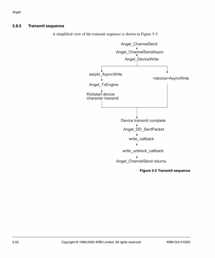
Angel
5.8.5 Transmit sequence
A simplified view of the transmit sequence is shown in Figure 5-5.
Figure 5-5 Transmit sequence
�!� ,����� ����
�!� ,����� ���� ����
�!� ,������2����
3������4 ����2����������, ����2����
�!� ,�'�!���
5���������������������������������
�������������������� ���
�!� ,��,����������
�����,�� )���
�����,#�) ���,�� )���
�!� ,����� ��������#���
5-52 Copyright © 1999-2002 ARM Limited. All rights reserved. ARM DUI 0102G

Angel
5.8.6 Receive sequence
A simplified view of the transmit sequence is shown in Figure 5-6.
Figure 5-6 Receive sequence
������#��
����������
������,���,�,���������!
�!� ,����� ,��!���������
���������������������#�����
�!� ,��������!���������
��!� ,��,6��������
����,�� )���
����� ������������ )���
ARM DUI 0102G Copyright © 1999-2002 ARM Limited. All rights reserved. 5-53

Angel
5-54 Copyright © 1999-2002 ARM Limited. All rights reserved. ARM DUI 0102G

Chapter 6 Flash Library Specification
This chapter provides the complete functional specification of the ARM flash library and the various ways it can be used.
This chapter contains the following sections:
• About the flash library on page 6-2
• About flash management on page 6-4
• ARM flash library specifications on page 6-5
• Functions listed by type on page 6-14
• Flash library functions on page 6-19
• File processing functions on page 6-35
• SIB functions on page 6-40
• Using the library on page 6-47.
See also Chapter 3 ARM Boot Monitor and Chapter 7 Using the ARM Flash Utilities for additional information about images in flash memory.
ARM DUI 0102G Copyright © 1999-2002 ARM Limited. All rights reserved. 6-1

Flash Library Specification
6.1 About the flash library
Current ARM development boards (such as Integrator) contain a large area of flash memory. This space is used to store many programs and associated data in a block structure, as defined in Image management on page 6-10.
The flash library divides the large flash memory structure into discrete blocks. In the case of the Integrator board, these are 128KB blocks. An image can contain any number of blocks, but it must conform to the flash library definition. Figure 6-1 shows the standard flash library image storage layout.
Figure 6-1 Flash library image storage layout
The following list describes the areas contained in Figure 6-1:
Image area
All of the code and read-only data segments of the image.
Header information
Any file header information from the downloaded file is placed after the image. (Not all images have header information.)
Image information
Added by the flash library code for image identification and code operations.
���!������ 1�!��� �) ����)�#�����
1�!��� �) ����)�#�����.��!��������/-�#����� ���
"�����������������
���!�������������
7�����������������
. ���������/
6-2 Copyright © 1999-2002 ARM Limited. All rights reserved. ARM DUI 0102G
Flash Library Specification
Unused flash
The footer must be at the end of the block of flash memory. The memory between the end of the image information and the footer is unused. If there is not room in the block containing the image for the footer, the footer will be placed at the end of the next block.
Footer information
A five-word information block containing:
• the address of the information block for this image
• the base address of the data (the start might be at the beginning of a previous block rather than at the start of this block)
• a unique 32-bit value to aid in fast searching
• the image type (that is, a block, an image, a SIB, or data)
• a checksum for the footer information (over the first four words only).
ARM DUI 0102G Copyright © 1999-2002 ARM Limited. All rights reserved. 6-3

Flash Library Specification
6.2 About flash management
Some embedded systems incorporate large areas of static programmable memory and require a mechanism to allocate, program, and pass control to images of varying size. This section describes the mechanism for programming flash, how multiple images are programmed into flash, and how images are selected for automatic execution.
The main characteristics of the ARM Flash Utility (AFU) and ARM flash library structure are:
• The library images use a footer rather than a header. For executable images and structured data, the existence of a header complicates using the image.
• The library manages memory in standard, small block sizes that hide detail from the normal user. The block size can be defined to provide a reasonable mix of flexibility and efficiency.
• The AFU supports the following image formats:
— ELF
— binary
— Motorola S-record
— Intel hex format
— Compressed binary.
Binary images require additional information to be defined by the build system in addition to the data contained in the file. AFU automatically identifies the file type from the image it receives.
• The AFU removes headers where possible. This ensures that the first word of the image is real image data, as it would be in a final product.
• Images occupy sequential flash locations.
6-4 Copyright © 1999-2002 ARM Limited. All rights reserved. ARM DUI 0102G
Flash Library Specification
6.3 ARM flash library specifications
This section discusses the general uses for the flash library and the flash types it supports. It also describes how image management is performed in the following sections:
• Code portability
• Accessing flash
• flashPhysicalType structure on page 6-6
• flashType structure on page 6-9
• Flash types on page 6-10
• Image management on page 6-10
• Porting the Flash Library on page 6-13.
The boot monitor also uses flash memory to store information about images. These System Information Blocks (SIBs) are application-specific. For information on the SIBs, see Chapter 3 ARM Boot Monitor.
6.3.1 Code portability
The flash programming library provides a standard access mechanism. The building blocks for common flash types simplify porting by:
• declaring where the flash memory is located
• identifying the type of flash
• declaring the size of the flash
• linking with the library.
The library guarantees a common access mechanism between the boot switcher, AFU, and other programming mechanisms.
A simple board-specific layer enables rapid porting to platforms that use supported flash types. Since all flash access is performed through routines defined in the board-specific layer, it is easy to add support for new types.
6.3.2 Accessing flash
Primary routines are supplied that allow access to on-board flash and allow an application to:
• check that there is actually flash at a given location
• write a word
• read a word
• erase a block of flash
• program a block of flash.
ARM DUI 0102G Copyright © 1999-2002 ARM Limited. All rights reserved. 6-5

Flash Library Specification
Note The flash device must not be cached or protected (by the MMU or MPU) while being programmed. On systems with a MMU, flash memory is often cached to improve code execution. On such systems flash can be mapped twice, with the second mapping set to be noncacheable for use when writing to the device. The flash management code (and the debug agent) cannot execute from the same flash part as the flash part that is being programmed.
6.3.3 flashPhysicalType structure
At the lowest level, the flash memory is using the flashPhysicalType device structure. Table 6-1 and Table 6-2 on page 6-9 lists the contents of the device structure of the flash library. These physical device structures are accessed by the library using the flashType device structure.
Table 6-1 Physical structure routines
FieldSize (bytes)
Value/usage
base 4 Virtual base address of this flash device for reads (normal access).
writeBase 4 Virtual base address of this flash device for writes. This can be the same as the read address if there are no caches or if caches are disabled, or can be a different address that is defined as noncacheable.
physicalBase 4 The base address of this flash device before any memory management is enabled. This is used by applications that run from reset and use these structures to access data/programs in flash (for example, bootMonitor).
width 4 Width of flash device, in bits.
parallel 4 Number of 8-bit or 16-bit devices installed in parallel to emulate a wider data path.
size 4 Size of flash, in bytes.
type 4 Atmel, Intel or other CFI manufacturers, AMD, or unknown type.
writeSize 4 Size of the physical flash block when writing data. Many devices can be programmed much faster using a block-programming algorithm.
eraseSize 4 Size of the physical flash block when erasing data. Some devices support different erase/write block sizes
logicalSize 4 Size of the logical flash block. If a device supports very small physical blocks, it may be easier to group these together to simplify flash access.
6-6 Copyright © 1999-2002 ARM Limited. All rights reserved. ARM DUI 0102G

Flash Library Specification
write() 4 Pointer to a routine to write one 32-bit word to flash.
writeBlock() 4 Pointer to a routine to write a block of writeSize bytes to flash.
read() 4 Pointer to a routine to read one 32-bit word from flash.
readBlock() 4 Pointer to a routine to read a block of writeSize bytes from flash.
erase() 4 Pointer to a routine to delete a block of eraseSize from flash.
init() 4 Pointer to a routine to unlock flash to allow erasure and programming.
close() 4 Pointer to a routine to lock flash to prevent erasure or programming.
query() 4 Pointer to a routine to query the flash to ensure that size is correct. This allows an application to determine at run-time how much flash is fitted on a platform.
Info 64 An ASCII string, used to identify the device (NULL-terminated).
next 4 Pointer to the next flash device structure.
Table 6-1 Physical structure routines (continued)
FieldSize (bytes)
Value/usage
ARM DUI 0102G Copyright © 1999-2002 ARM Limited. All rights reserved. 6-7

Flash Library Specification
The library defines a C structure, shown in Example 6-1, for the physical flash definition so that all offsets from the first word are abstracted.
Example 6-1 flashPhysicalType structure
typedef int32 flFlash_WriteProc(char *address, unsigned32 data, char *flash);typedef int32 flFlash_WriteBlockProc(char *address, unsigned32 *data, unsigned32 size, char *flash, int width);typedef int32 flFlash_ReadProc(char *address, unsigned32 *value);typedef int32 flFlash_ReadBlockProc(char *address, unsigned32 *data, unsigned32 size);typedef int32 flFlash_EraseProc(char *address, unsigned32 size, char *flash, int width);typedef int32 flFlash_InitProc(char *address, int width);typedef int32 flFlash_CloseProc(char *address, int width);typedef int32 flFlash_QueryProc(void *flash);
typedef struct flashPhysicalType{ // Base Addresses for the start of this 'device' char *base // Virtual address of flash for reads (normal access) char *writeBase // Virtual address of flash for writes char *physicalBase // This is the location where flash can be accessed // _before_ any memory management is enabled unsigned32 width; // Width of flash access on this platform (bits) unsigned32 parallel; // Number of devices in parallel across databus unsigned32 size; // Size of flash, in bytes unsigned32 type; // Atmel / Intel (CFI) / AMD / Unknown unsigned32 writeSize; // Size of physical block unsigned32 eraseSize; // Size of block erase unsigned32 logicalSize; // Size of logical block // Pointers to routines which perform operations on this device flFlash_WriteProc *write; // Write one word flFlash_WriteBlockProc *writeBlock; // Write a block of writeSize bytes flFlash_ReadProc *read; // Read one word flFlash_ReadBlockProc *readBlock; // Read a block of writeSize bytes flFlash_EraseProc *erase; // Erase a block of eraseSize bytes flFlash_InitProc *init; // Unlock a flash device flFlash_CloseProc *close; // Lock a flash device flFlash_QueryProc *query; // Query a flash device (size etc) char info[64]; // Null terminated Info string struct flashPhysicalType *next; // Pointer to next flash device}tPhysicalFlash;
6-8 Copyright © 1999-2002 ARM Limited. All rights reserved. ARM DUI 0102G
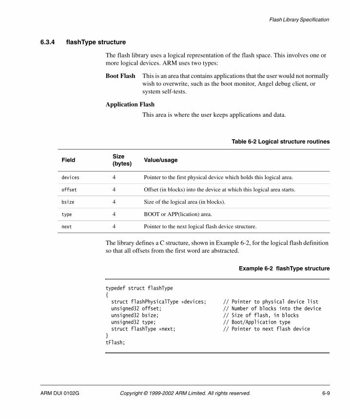
Flash Library Specification
6.3.4 flashType structure
The flash library uses a logical representation of the flash space. This involves one or more logical devices. ARM uses two types:
Boot Flash This is an area that contains applications that the user would not normally wish to overwrite, such as the boot monitor, Angel debug client, or system self-tests.
Application Flash
This area is where the user keeps applications and data.
The library defines a C structure, shown in Example 6-2, for the logical flash definition so that all offsets from the first word are abstracted.
Example 6-2 flashType structure
typedef struct flashType{ struct flashPhysicalType *devices; // Pointer to physical device list unsigned32 offset; // Number of blocks into the device unsigned32 bsize; // Size of flash, in blocks unsigned32 type; // Boot/Application type struct flashType *next; // Pointer to next flash device}tFlash;
Table 6-2 Logical structure routines
FieldSize (bytes)
Value/usage
devices 4 Pointer to the first physical device which holds this logical area.
offset 4 Offset (in blocks) into the device at which this logical area starts.
bsize 4 Size of the logical area (in blocks).
type 4 BOOT or APP(lication) area.
next 4 Pointer to the next logical flash device structure.
ARM DUI 0102G Copyright © 1999-2002 ARM Limited. All rights reserved. 6-9

Flash Library Specification
6.3.5 Flash types
The library supports the following flash types:
Intel For specifications and general information on the Intel 28Fxxx parts that use the Common Flash Interface, contact Intel or visit the Intel web site. (Not all Intel parts use the common flash interface.)
Atmel For specifications and general information on the Atmel flash devices, contact Atmel or visit the Atmel web site. These parts do not use the Common Flash Interface protocol.
AMD For specifications and general information on the AMD flash devices, contact AMD or visit the AMD web site. These parts only use the Common Flash Interface protocol to query the device.
SST For specifications and general information on the SST flash devices, contact SST or visit the SST web site. These parts use the Common Flash Interface protocol only to query the device. The SST devices supported use the same programming mechanism as AMD, but with a different command set.
6.3.6 Image management
At the end of the last block of an image, the flash management program writes a data record, or footer, that contains information about the image, such as name, start location, and checksum. If the footer cannot fit into the last block of the image, it must be written at the end of the next block (the block fields update accordingly). If this footer is not written, the image is not visible to the boot switcher, and it will not be visible when the flash management program is next run.
6-10 Copyright © 1999-2002 ARM Limited. All rights reserved. ARM DUI 0102G

Flash Library Specification
Footer structure
The footer structure is a five-word device that contains a pointer to a more detailed structure that, if required, defines the image.
Table 6-3 shows the format for the footer.
The image base address is the start of the first block containing data for this image. If the image is less than one logical block in length, this pointer will be set to the start of the current block.
The library defines a C structure for the footer so that all offsets from the first word are abstracted. Example 6-3 shows this structure.
Example 6-3 FooterType structure
typedef struct FooterType { void *infoBase ; /* Address of first word of ImageFooter */ char *blockBase ; /* Start of area reserved by this footer */ unsigned int signature /* 'Magic' number to prove it's a footer */ unsigned int type ; /* Area type: ARM image, SIB, customer*/ unsigned int checksum ; /* Checksum of this structure only */} tFooter ;
Table 6-3 Footer format
FieldSize (bytes)
Value/usage
Image information base 4 Pointer to the full image descriptor structure.
Image base address 4 Location in flash memory where the image starts.
Signature 4 0xA0FFFF9F is an illegal instruction in the ARM instruction set. It can never be produced by compilers as code, so it is a relatively safe value for a unique signature.
Image type 4 Indicates an ARM executable image, SIB, or custom code.
Checksum 4 Checksum for this footer. The checksum is the word sum (with the carry wrapped into the least significant bit) and is stored as the inverse of the sum.
ARM DUI 0102G Copyright © 1999-2002 ARM Limited. All rights reserved. 6-11

Flash Library Specification
ImageInfo structure
Because the library supports different program image formats, the actual flash programming is separate from image loading. Table 6-4 describes the C structure that holds information about the image.
This structure replicates much of the information contained in the header of file formats such as Executable and Linkable Format (ELF) in a form that is accessible to the file-independent routines.
The image data structure contains information about any file header stored in the image space to allow reconstruction of the file, if required.
Table 6-4 ImageInfo structure
FieldSize (bytes)
Value/usage
Image boot flags 4 The boot requirements for the image: Bit 0: NOBOOT. If set, this image is not bootable. The boot switcher ignores it when selecting an image to run. Bit 1: COMPRESSED. If set, this image must be decompressed before being copied into memory. Bit 2: Initialize memory (and MMU) before executing the image. Bit 3: Copy the image into memory before executing it. Bit 4: File system image (SIB).
Unique image number 4 Number defined to allow fast searches for the image and easy execution. This is a logical image number and is not related to the order of the images in flash.
Image load address 4 Location in memory where the image must be loaded for execution, if relevant.
Image length 4 Length of image in memory, in bytes, excluding any file header.
Image execute address 4 Execution address of the image in memory.
Image name 16 Name of the image as a 16-byte, null-terminated string.
Header length 4 Length of any separated header stored with the image.
Header type 4 Type of file: ELF, binary, or S-record.
Image checksum 4 Checksum to include full image, header, and this image information block. The checksum is the word sum (with the carry wrapped into the least significant bit) and is stored as the inverse of the sum.
6-12 Copyright © 1999-2002 ARM Limited. All rights reserved. ARM DUI 0102G

Flash Library Specification
The image information block is situated immediately after the full image, and any header information is stripped from the input file and stored with the image. The checksum is calculated from the full image, any header information, and the image information block. Example 6-4 shows the ImageInfoType structure.
Example 6-4 ImageInfoType structure
typedef struct ImageInfoType { unsigned32 bootFlags ; /* Boot flags, compression etc. */ unsigned32 imageNumber ; /* Unique number, selects for boot etc. */ char *loadAddress ; /* Address program should be loaded to */ unsigned32 length ; /* Actual size of image */ PFN address ; /* Image is executed from here */ char name[16] ; /* Null terminated */ char *headerBase ; /* Flash Address of any stripped header */ unsigned32 header_length; /* Length of header in memory */ unsigned32 headerType ; /* ELF, S-record etc. */ unsigned32 checksum ; /* Image checksum (inc. this struct) */} tImageInfo ;
6.3.7 Porting the Flash Library
A simple board-specific layer enables rapid porting to platforms which use supported flash types. Because all flash access is performed through routines defined in the board-specific layer, adding support for new types is not complex, and consists of the following simple steps:
• Define the physical structures
• Define the logical structures
• Write the platform-specific routines as specified in Flash library functions, listed by type on page 6-14.
ARM DUI 0102G Copyright © 1999-2002 ARM Limited. All rights reserved. 6-13

Flash Library Specification
6.4 Functions listed by type
This section lists the library functions by type. The functions are grouped into the following main categories:
• Functions that directly access flash memory are described in Flash library functions, listed by type.
• Functions related to file structures are described in File processing functions, listed by type on page 6-16.
• Functions related to application-defined nonvolatile storage areas are described in SIB functions on page 6-18.
6.4.1 Flash library functions, listed by type
This section list the functions that directly access flash memory, and shows where further information can be found on each function.
Platform-specific routines
There are just two platform-specific routines. These are used to activate any mechanisms to lock and unlock write-access to flash. The routines are:
• Flash_Write_Enable() on page 6-19
• Flash_Write_Disable() on page 6-19.
Locating flash
Because accessing the flash area on one platform might cause an exception on another, it is difficult to locate the flash. Linking platform-specific code that defines the base of flash memory allows common applications, such as the download to flash feature of the ARM debuggers, to work on all supported platforms.
The flash device structure allows you to handle multiple flash parts in a common manner by the library or an application. If a device has an area that can be locked, it can be presented as two logical devices, partitioned into lockable and nonlockable. The functions for locating flash are:
• fLib_DefinePlat() on page 6-20
• fLib_FindFlash() on page 6-20
• fLib_OpenFlash() on page 6-21.
6-14 Copyright © 1999-2002 ARM Limited. All rights reserved. ARM DUI 0102G
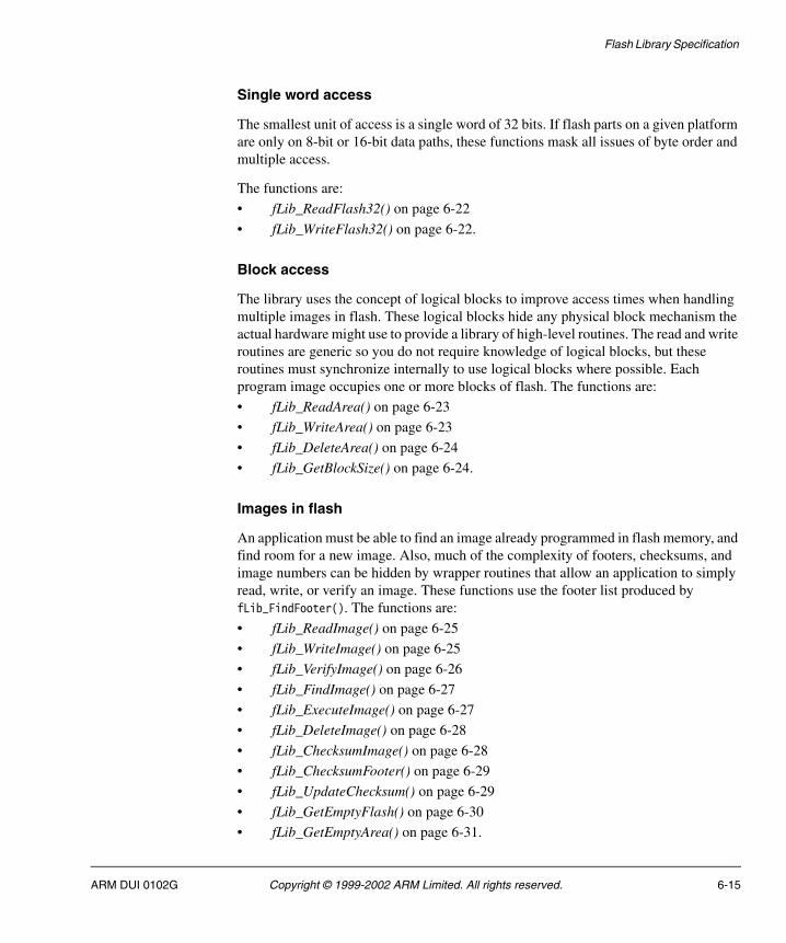
Flash Library Specification
Single word access
The smallest unit of access is a single word of 32 bits. If flash parts on a given platform are only on 8-bit or 16-bit data paths, these functions mask all issues of byte order and multiple access.
The functions are:
• fLib_ReadFlash32() on page 6-22
• fLib_WriteFlash32() on page 6-22.
Block access
The library uses the concept of logical blocks to improve access times when handling multiple images in flash. These logical blocks hide any physical block mechanism the actual hardware might use to provide a library of high-level routines. The read and write routines are generic so you do not require knowledge of logical blocks, but these routines must synchronize internally to use logical blocks where possible. Each program image occupies one or more blocks of flash. The functions are:
• fLib_ReadArea() on page 6-23
• fLib_WriteArea() on page 6-23
• fLib_DeleteArea() on page 6-24
• fLib_GetBlockSize() on page 6-24.
Images in flash
An application must be able to find an image already programmed in flash memory, and find room for a new image. Also, much of the complexity of footers, checksums, and image numbers can be hidden by wrapper routines that allow an application to simply read, write, or verify an image. These functions use the footer list produced by fLib_FindFooter(). The functions are:
• fLib_ReadImage() on page 6-25
• fLib_WriteImage() on page 6-25
• fLib_VerifyImage() on page 6-26
• fLib_FindImage() on page 6-27
• fLib_ExecuteImage() on page 6-27
• fLib_DeleteImage() on page 6-28
• fLib_ChecksumImage() on page 6-28
• fLib_ChecksumFooter() on page 6-29
• fLib_UpdateChecksum() on page 6-29
• fLib_GetEmptyFlash() on page 6-30
• fLib_GetEmptyArea() on page 6-31.
ARM DUI 0102G Copyright © 1999-2002 ARM Limited. All rights reserved. 6-15
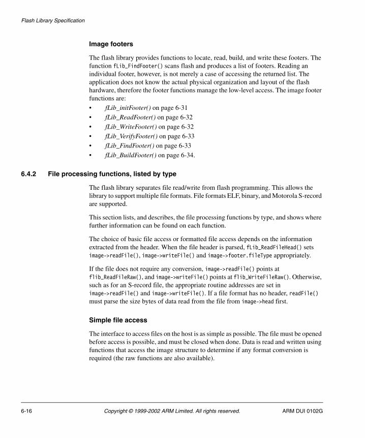
Flash Library Specification
Image footers
The flash library provides functions to locate, read, build, and write these footers. The function fLib_FindFooter() scans flash and produces a list of footers. Reading an individual footer, however, is not merely a case of accessing the returned list. The application does not know the actual physical organization and layout of the flash hardware, therefore the footer functions manage the low-level access. The image footer functions are:
• fLib_initFooter() on page 6-31
• fLib_ReadFooter() on page 6-32
• fLib_WriteFooter() on page 6-32
• fLib_VerifyFooter() on page 6-33
• fLib_FindFooter() on page 6-33
• fLib_BuildFooter() on page 6-34.
6.4.2 File processing functions, listed by type
The flash library separates file read/write from flash programming. This allows the library to support multiple file formats. File formats ELF, binary, and Motorola S-record are supported.
This section lists, and describes, the file processing functions by type, and shows where further information can be found on each function.
The choice of basic file access or formatted file access depends on the information extracted from the header. When the file header is parsed, fLib_ReadFileHead() sets image->readFile(), image->writeFile() and image->footer.fileType appropriately.
If the file does not require any conversion, image->readFile() points at flib_ReadFileRaw(), and image->writeFile() points at flib_WriteFileRaw(). Otherwise, such as for an S-record file, the appropriate routine addresses are set in image->readFile() and image->writeFile(). If a file format has no header, readFile() must parse the size bytes of data read from the file from image->head first.
Simple file access
The interface to access files on the host is as simple as possible. The file must be opened before access is possible, and must be closed when done. Data is read and written using functions that access the image structure to determine if any format conversion is required (the raw functions are also available).
6-16 Copyright © 1999-2002 ARM Limited. All rights reserved. ARM DUI 0102G
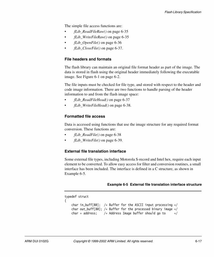
Flash Library Specification
The simple file access functions are:
• fLib_ReadFileRaw() on page 6-35
• fLib_WriteFileRaw() on page 6-35
• fLib_OpenFile() on page 6-36
• fLib_CloseFile() on page 6-37.
File headers and formats
The flash library can maintain an original file format header as part of the image. The data is stored in flash using the original header immediately following the executable image. See Figure 6-1 on page 6-2.
The file inputs must be checked for file type, and stored with respect to the header and code image information. There are two functions to handle parsing of the header information to and from the flash image space:
• fLib_ReadFileHead() on page 6-37
• fLib_WriteFileHead() on page 6-38.
Formatted file access
Data is accessed using functions that use the image structure for any required format conversion. These functions are:
• fLib_ReadFile() on page 6-38
• fLib_WriteFile() on page 6-39.
External file translation interface
Some external file types, including Motorola S-record and Intel hex, require each input element to be converted. To allow easy access for filter and conversion routines, a small interface has been included. The interface is defined in a C structure, as shown in Example 6-5.
Example 6-5 External file translation interface structure
typedef struct { char in_buff[80]; /* Buffer for the ASCII input processing */ char out_buff[80]; /* Buffer for the processed binary image */ char * address; /* Address Image buffer should go to */
ARM DUI 0102G Copyright © 1999-2002 ARM Limited. All rights reserved. 6-17

Flash Library Specification
int rec_length; /* Actual size of image buffer */ int records; /* Internal counter for block passage */} tProcess_type ;
Parameters are in the format shown in Table 6-5.
The external processing function uses the tProcess_type structure to translate the file on a line-by-line basis and give the correct data and storage address to the input function.
There are no individual external file translation interface routines.
6.4.3 SIB functions
Applications sometimes need small amounts of nonvolatile storage. The boot monitor, for example, requires a small block of data to identify which image to run. These small blocks of application-specific information are provided as System Information Blocks (SIB).
The following functions are available to create and access SIBs:
• SIB_Open() on page 6-42
• SIB_Close() on page 6-43
• SIB_GetPointer() on page 6-43
• SIB_Copy() on page 6-44
• SIB_Program() on page 6-44
• SIB_GetSize() on page 6-45
• SIB_Verify() on page 6-45
• SIB_Erase() on page 6-46.
Table 6-5 Parameters
FieldSize inbytes
Value/usage
in_buff 80 Input line buffer for the ASCII element read in from an external file.
out_buff 80 Storage space for conversion output.
address 4 Address for storage, taken from the element header.
rec_length 4 True element size taken from the element being processed.
records 4 Internal counter for the process type to show the number of elements processed.
6-18 Copyright © 1999-2002 ARM Limited. All rights reserved. ARM DUI 0102G

Flash Library Specification
6.5 Flash library functions
This section documents the functions in the flash library. The functions are listed in the order as documented in Flash library functions, listed by type on page 6-14. All functions and type definitions are contained in flash_lib.h.
6.5.1 Flash_Write_Enable()
This function will unlock all devices of the specified type. If the target platform requires some initialization to enable writing to flash, it should be defined here.
Syntax
int Flash_Write_Enable(int type)
where:
type Is a flash type as defined in flash_lib.h.
Return value
Returns one of the following:
0 If successful.
-1 If not successful.
6.5.2 Flash_Write_Disable()
This function will lock all devices of the specified type. If the target platform requires some initialization to disable writing to flash, it should be defined here.
Syntax
int Flash_Write_Disable(int type)
where:
type Is a flash type as defined in flash_lib.h.
Return value
Returns one of the following:
0 If successful.
-1 If not successful.
ARM DUI 0102G Copyright © 1999-2002 ARM Limited. All rights reserved. 6-19

Flash Library Specification
6.5.3 fLib_DefinePlat()
This function defines logical structures used by the library. The library accesses flash using these logical structures which contain pointers to physical devices and pointers to other logical devices.
Syntax
unsigned int fLib_DefinePlat(tFlash **tf)
where:
tf Is the address of a pointer that will be set to the address of the flashType device structure in the system.
Return value
Returns one of the following:
0 If flash is found.
*tf is set to the address of the first element of the array of device structures.
-1 If no flash is found
6.5.4 fLib_FindFlash()
This function locates the flash memory devices on this platform. If there is more than one device in the system, the application must build a linked list of devices before calling fLib_OpenFlash().
Syntax
unsigned int fLib_FindFlash(tFlash **tf)
where:
tf Is the address of a pointer that will be set to the address of the first flashType device structure in the system.
6-20 Copyright © 1999-2002 ARM Limited. All rights reserved. ARM DUI 0102G
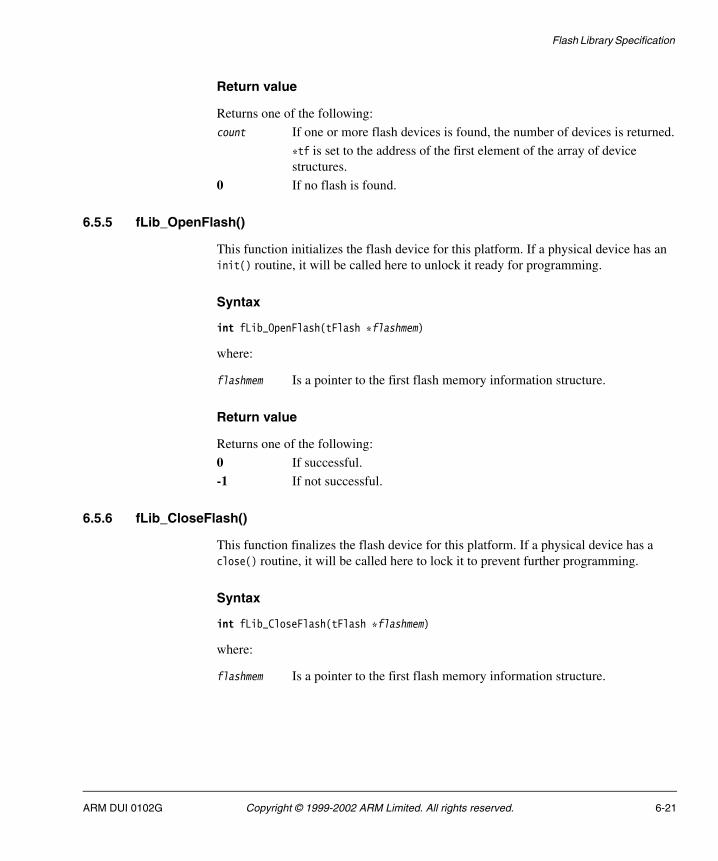
Flash Library Specification
Return value
Returns one of the following:
count If one or more flash devices is found, the number of devices is returned.
*tf is set to the address of the first element of the array of device structures.
0 If no flash is found.
6.5.5 fLib_OpenFlash()
This function initializes the flash device for this platform. If a physical device has an init() routine, it will be called here to unlock it ready for programming.
Syntax
int fLib_OpenFlash(tFlash *flashmem)
where:
flashmem Is a pointer to the first flash memory information structure.
Return value
Returns one of the following:
0 If successful.
-1 If not successful.
6.5.6 fLib_CloseFlash()
This function finalizes the flash device for this platform. If a physical device has a close() routine, it will be called here to lock it to prevent further programming.
Syntax
int fLib_CloseFlash(tFlash *flashmem)
where:
flashmem Is a pointer to the first flash memory information structure.
ARM DUI 0102G Copyright © 1999-2002 ARM Limited. All rights reserved. 6-21

Flash Library Specification
Return value
Returns one of the following:
0 If successful.
-1 If not successful.
6.5.7 fLib_ReadFlash32()
This function calls the read() function from the appropriate physical device pointed to by the flashmem structure and reads one 32-bit word from the flash at the given address.
Syntax
int fLib_ReadFlash32(unsigned int *address, unsigned int *value, tFlash *flashmem)
where:
address Is a pointer to the address of the flash memory to be read.
value Is a pointer to the memory address where the flash should be copied.
flashmem Is a pointer to the flash device structure to allow access to the flash read/write routines.
Return value
Returns one of the following:
0 If successful. The memory at value now holds the results.
-1 If not successful.
6.5.8 fLib_WriteFlash32()
This function writes one 32-bit word to the flash at the given address.
Syntax
int fLib_WriteFlash32(unsigned int *address, unsigned int value, tFlash *flashmem)
where:
address Is a pointer to the address of the flash memory to be written to.
value Is the data to be written to the specified flash address.
flashmem Is a pointer to the flash device structure to allow access to the flash read/write routines.
6-22 Copyright © 1999-2002 ARM Limited. All rights reserved. ARM DUI 0102G
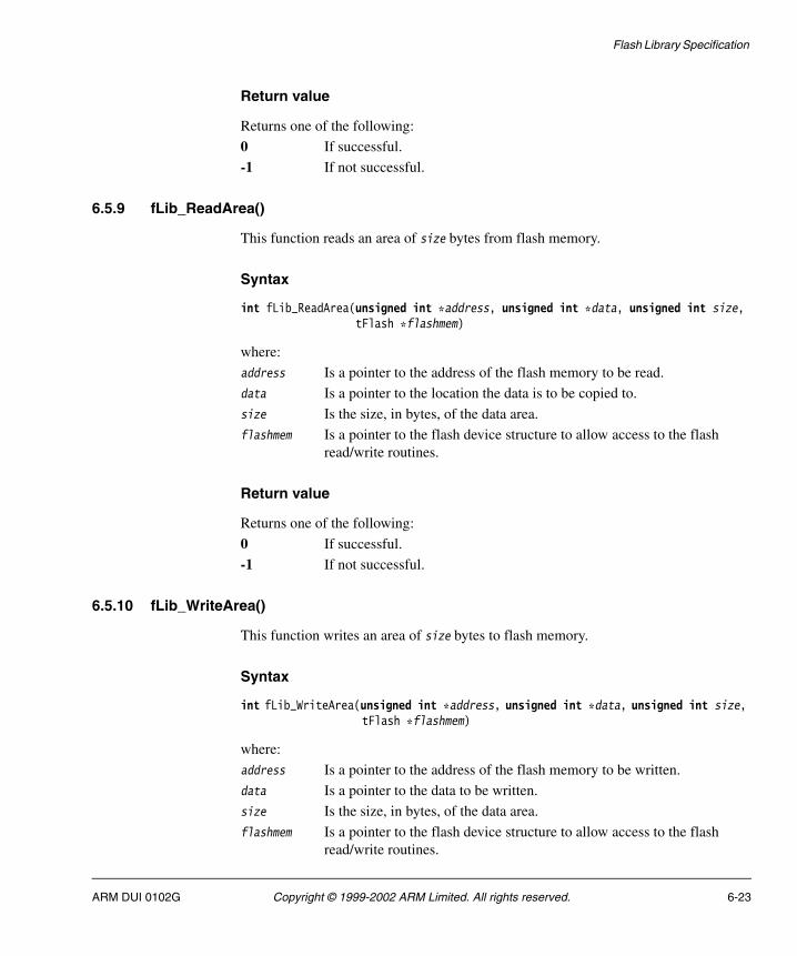
Flash Library Specification
Return value
Returns one of the following:
0 If successful.
-1 If not successful.
6.5.9 fLib_ReadArea()
This function reads an area of size bytes from flash memory.
Syntax
int fLib_ReadArea(unsigned int *address, unsigned int *data, unsigned int size, tFlash *flashmem)
where:
address Is a pointer to the address of the flash memory to be read.
data Is a pointer to the location the data is to be copied to.
size Is the size, in bytes, of the data area.
flashmem Is a pointer to the flash device structure to allow access to the flash read/write routines.
Return value
Returns one of the following:
0 If successful.
-1 If not successful.
6.5.10 fLib_WriteArea()
This function writes an area of size bytes to flash memory.
Syntax
int fLib_WriteArea(unsigned int *address, unsigned int *data, unsigned int size, tFlash *flashmem)
where:
address Is a pointer to the address of the flash memory to be written.
data Is a pointer to the data to be written.
size Is the size, in bytes, of the data area.
flashmem Is a pointer to the flash device structure to allow access to the flash read/write routines.
ARM DUI 0102G Copyright © 1999-2002 ARM Limited. All rights reserved. 6-23

Flash Library Specification
Return value
Returns one of the following:
0 If successful.
-1 If not successful.
6.5.11 fLib_DeleteArea()
This function deletes (erases) an area of flash memory.
Syntax
int fLib_DeleteArea(unsigned int *address, unsigned int size, tFlash *flashmem)
where:
address Is a pointer to the address of the flash memory to be erased.
size Is the size, in bytes, of the data area to be erased.
flashmem Is a pointer to the flash device structure to allow access to the flash read/write routines.
Return value
Returns one of the following:
0 If successful.
-1 If not successful.
6.5.12 fLib_GetBlockSize()
This function returns the size, in bytes, of the logical block for this platform.
Note These logical blocks cannot be smaller than the largest device physical block size. This block size will be a multiple of the erase block size.
Syntax
unsigned int fLib_GetBlockSize(tFlash *flashmem)
where:
flashmem Is a pointer to the flash device structure to return the size.
6-24 Copyright © 1999-2002 ARM Limited. All rights reserved. ARM DUI 0102G

Flash Library Specification
Return value
Returns one of the following:
size If the flash block size can be determined, the size of the block is returned.
0 If the size cannot be determined.
6.5.13 fLib_ReadImage()
This function reads the image from flash memory as defined in foot. The destination specified by the foot->infoBase->loadAddress pointer cannot be NULL.
Syntax
int fLib_ReadImage(tFooter *foot, tFlash *flashmem)
where:
foot Is a pointer to the footer structure defining the image pointer for the image to be read.
flashmem Is a pointer to the flash device structure to allow access to the flash read/write routines.
Return value
Returns one of the following:
0 If successful.
-1 If not successful.
6.5.14 fLib_WriteImage()
This function writes the image selected by the specified image structure. The image structure must be fully defined.
Syntax
int fLib_WriteImage(tImageInfo *image, tFlash *flashmem, unsigned32 *current, tFooter *foot)
ARM DUI 0102G Copyright © 1999-2002 ARM Limited. All rights reserved. 6-25

Flash Library Specification
where:
image Is a pointer to the image structure for the image to be copied.
flashmem Is a pointer to the flash device structure to allow access to the flash read/write routines.
current Is a pointer to the start of the image in RAM.
foot Is a pointer to the footer structure defining the image pointer for the image to be copied.
Return value
Returns one of the following:
0 If successful.
-1 If not successful.
6.5.15 fLib_VerifyImage()
This function verifies that the image, selected by the specified image structure, matches the image as programmed. The image structure must be fully defined.
Syntax
int fLib_VerifyImage(tFooter *foot, tFlash *flashmem)
where:
foot Is a pointer to the footer structure defining the image pointer for the image to be verified.
flashmem Is a pointer to the flash device structure to allow access to the flash read/write routines.
Return value
Returns one of the following:
0 If successful.
-1 If not successful.
6-26 Copyright © 1999-2002 ARM Limited. All rights reserved. ARM DUI 0102G

Flash Library Specification
6.5.16 fLib_FindImage()
This function scans the list of flash footers looking for a footer with an image number that matches the specified number. If the specified footer pointer is not NULL, the footer is copied from flash.
Syntax
int fLib_FindImage(tFooter **list, unsigned int imageNo, tFooter *foot, tFlash *flashmem)
where:
list Is a pointer to a list of pointers to footers.
imageNo Is the unique number of the image to be located.
foot Is a pointer to the location where the found footer should be copied.
flashmem Is a pointer to the flash device structure to allow access to the flash read/write routines.
Return value
Returns one of the following:
0 If successful.
-1 If not successful.
6.5.17 fLib_ExecuteImage()
This function executes the image selected by the specified image footer.
Syntax
int fLib_ExecuteImage(tFooter *foot)
where:
foot Is a pointer to the footer that defines the image to be executed.
Return value
Returns one of the following:
No return If successful, the function does not return.
-1 If not successful.
ARM DUI 0102G Copyright © 1999-2002 ARM Limited. All rights reserved. 6-27

Flash Library Specification
6.5.18 fLib_DeleteImage()
This function deletes the image in flash selected by the specified image footer.
Syntax
int fLib_DeleteImage(tFooter *foot, tFlash *flashmem)
where:
foot Is a pointer to the footer that defines the image to be deleted.
flashmem Is a pointer to the flash device structure to allow access to the flash read/write routines.
Return value
Returns one of the following:
0 If successful.
-1 If not successful.
6.5.19 fLib_ChecksumImage()
This function calculates the checksum for the specified image. The image structure and associated footer must be fully defined, but the contents of the image structure are not summed. The checksum is a word sum, and is inverted before being stored.
Syntax
int fLib_ChecksumImage(tFooter *foot, unsigned int *sum, tFlash *flashmem)
where:
foot Is a pointer to the footer structure defining the image pointer for the image to be check-summed.
sum Is a pointer to the (non-flash) location where the image checksum is to be stored.
flashmem Is a pointer to the flash device structure to allow access to the flash read/write routines.
6-28 Copyright © 1999-2002 ARM Limited. All rights reserved. ARM DUI 0102G
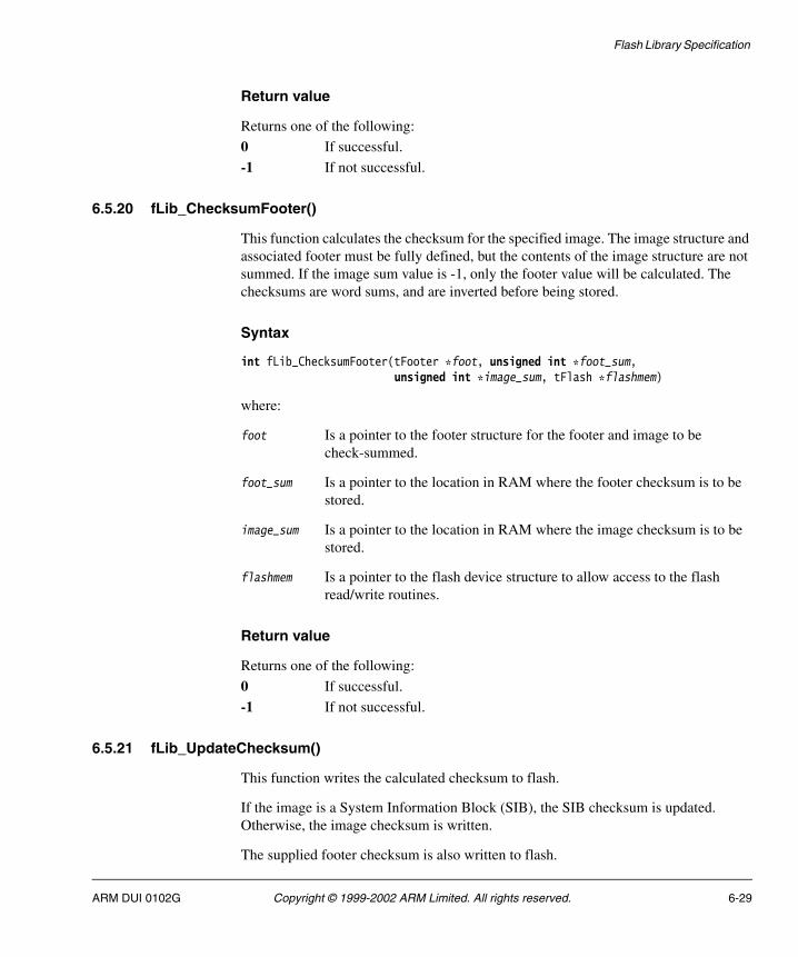
Flash Library Specification
Return value
Returns one of the following:
0 If successful.
-1 If not successful.
6.5.20 fLib_ChecksumFooter()
This function calculates the checksum for the specified image. The image structure and associated footer must be fully defined, but the contents of the image structure are not summed. If the image sum value is -1, only the footer value will be calculated. The checksums are word sums, and are inverted before being stored.
Syntax
int fLib_ChecksumFooter(tFooter *foot, unsigned int *foot_sum, unsigned int *image_sum, tFlash *flashmem)
where:
foot Is a pointer to the footer structure for the footer and image to be check-summed.
foot_sum Is a pointer to the location in RAM where the footer checksum is to be stored.
image_sum Is a pointer to the location in RAM where the image checksum is to be stored.
flashmem Is a pointer to the flash device structure to allow access to the flash read/write routines.
Return value
Returns one of the following:
0 If successful.
-1 If not successful.
6.5.21 fLib_UpdateChecksum()
This function writes the calculated checksum to flash.
If the image is a System Information Block (SIB), the SIB checksum is updated. Otherwise, the image checksum is written.
The supplied footer checksum is also written to flash.
ARM DUI 0102G Copyright © 1999-2002 ARM Limited. All rights reserved. 6-29

Flash Library Specification
Syntax
int fLib_UpdateChecksum(tFooter *foot, unsigned int im_check, unsigned int ft_check, tFlash *flashmem)
where:
foot Is a pointer to the footer structure for the footer and image to be check-summed.
im_check Is the checksum for the image or SIB.
ft_check Is the checksum for the footer structure.
flashmem Is a pointer to the flash device structure to allow access to the flash read/write routines.
Return value
Returns one of the following:
0 If successful.
-1 If not successful.
6.5.22 fLib_GetEmptyFlash()
This function scans the list of flash footers, looking for an empty area from start, of at least unused size.
Syntax
int fLib_GetEmptyFlash(tFooter **list, unsigned int *start, unsigned int *location, unsigned int empty, tFlash *flashmem)
where:
list Is a pointer to a list of pointers to footers.
start Is a pointer to the start location required in flash memory.
location Is a pointer to the start of the flash area capable of housing the image.
empty Is the size of the empty area required in flash memory.
flashmem Is a pointer to the location from where the footer image is to be copied.
6-30 Copyright © 1999-2002 ARM Limited. All rights reserved. ARM DUI 0102G

Flash Library Specification
Return value
Returns one of the following:
0 If successful.
-1 If not successful.
6.5.23 fLib_GetEmptyArea()
This function scans flash footers, looking for any empty area of at least empty size.
Syntax
int fLib_GetEmptyArea(tFooter **list, unsigned int empty, tFlash *flashmem)
where:
list Is a pointer to a list of pointers to footers.
empty Is the size of the empty area required in flash memory.
flashmem Is a pointer to the location from where the footer image is to be copied.
Return value
Returns one of the following:
0 If successful.
-1 If not successful.
6.5.24 fLib_initFooter()
This function initializes the footer at foot with known values (-1, or 0xFFFFFFFF). This sets up the footer to a known state. The value -1 is the general value of unprogrammed flash.
Syntax
int fLib_initFooter(tFooter *foot, int ImageSize, int type)
where:
foot Is a pointer to the footer structure for initialization.
ImageSize Is the size of the image, if known.
type Is a footer type such as an ARM executable or SIB (bit patterns defined in flash_lib.h).
ARM DUI 0102G Copyright © 1999-2002 ARM Limited. All rights reserved. 6-31
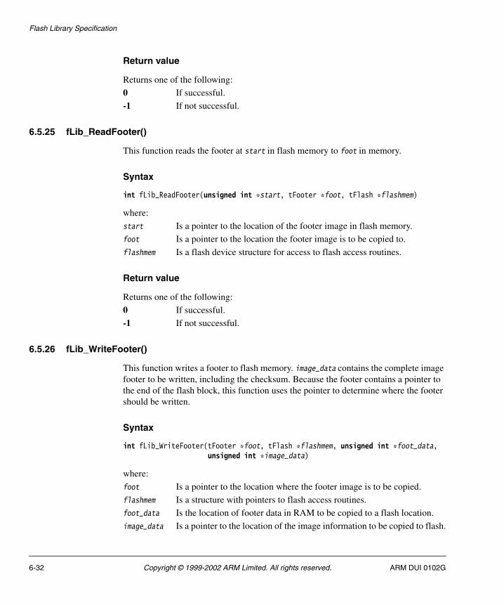
Flash Library Specification
Return value
Returns one of the following:
0 If successful.
-1 If not successful.
6.5.25 fLib_ReadFooter()
This function reads the footer at start in flash memory to foot in memory.
Syntax
int fLib_ReadFooter(unsigned int *start, tFooter *foot, tFlash *flashmem)
where:
start Is a pointer to the location of the footer image in flash memory.
foot Is a pointer to the location the footer image is to be copied to.
flashmem Is a flash device structure for access to flash access routines.
Return value
Returns one of the following:
0 If successful.
-1 If not successful.
6.5.26 fLib_WriteFooter()
This function writes a footer to flash memory. image_data contains the complete image footer to be written, including the checksum. Because the footer contains a pointer to the end of the flash block, this function uses the pointer to determine where the footer should be written.
Syntax
int fLib_WriteFooter(tFooter *foot, tFlash *flashmem, unsigned int *foot_data, unsigned int *image_data)
where:
foot Is a pointer to the location where the footer image is to be copied.
flashmem Is a structure with pointers to flash access routines.
foot_data Is the location of footer data in RAM to be copied to a flash location.
image_data Is a pointer to the location of the image information to be copied to flash.
6-32 Copyright © 1999-2002 ARM Limited. All rights reserved. ARM DUI 0102G

Flash Library Specification
Return value
Returns one of the following:
0 If successful.
-1 If not successful.
6.5.27 fLib_VerifyFooter()
This function verifies the footer at foot. It checks the signature word, and also checks that the checksum is correct.
Syntax
int fLib_VerifyFooter(tFooter *foot, tFlash *flashmem)
where:
foot Is a pointer to the footer image to be verified.
flashmem Is a structure with pointers to flash access routines.
Return value
Returns one of the following:
0 If successful.
-1 If not successful.
6.5.28 fLib_FindFooter()
This function scans the flash memory from start for size bytes, returning a list of pointers to the image footers.
Syntax
unsigned int fLib_FindFooter(unsigned int *start, unsigned int size, tFooter *list[], tFlash *flashmem)
ARM DUI 0102G Copyright © 1999-2002 ARM Limited. All rights reserved. 6-33

Flash Library Specification
where:
start Is a pointer to the address of the flash memory to be scanned.
size Is the size, in bytes, of the flash memory. If the size is defined as zero, only the address of the next footer found is returned.
list Is a pointer to a list of pointers to footers. The list must be large enough to contain:
• a pointer to each logical block of flash in the specified area
• a final pointer that will point to null.
flashmem Is a structure with pointers to flash access routines.
Return value
Returns the number of flash footers found.
6.5.29 fLib_BuildFooter()
This function builds a footer for the specified image. The image structure already contains all information about the program image in memory. This function must convert these pointers to their final values in flash.
Syntax
int fLib_BuildFooter(tFooter *foot, tFlash *flashmem)
where:
foot Is a pointer to the footer to be built.
flashmem Is a structure with pointers to flash access routines.
Return value
Returns one of the following:
0 If successful.
-1 If not successful.
6-34 Copyright © 1999-2002 ARM Limited. All rights reserved. ARM DUI 0102G

Flash Library Specification
6.6 File processing functions
This section documents the set of file processing function calls. The functions are listed in the order as documented in File processing functions, listed by type on page 6-16. All functions and type definitions are contained in flash_lib.h.
6.6.1 fLib_ReadFileRaw()
This function reads up to size bytes from the open file fp.
Syntax
unsigned int fLib_ReadFileRaw(unsigned int *value, unsigned int size, tFile_IO *file_IO, tFILE *fp)
where:
value Is a pointer to the destination memory address to which the contents of the file is copied.
size Is the number of bytes to be read.
file_IO Is a pointer to a structure that accesses the external file input/output by way of simple input/output routines.
fp Is a pointer to an open file stream from which to read file data.
Return value
Returns one of the following:
count If successful, the number of bytes read is returned.
0 If not successful.
6.6.2 fLib_WriteFileRaw()
This function writes up to size bytes to the open file fp.
Syntax
unsigned int fLib_WriteFileRaw(unsigned int *value, unsigned int size, tFile_IO *file_IO, tFILE *fp)
ARM DUI 0102G Copyright © 1999-2002 ARM Limited. All rights reserved. 6-35
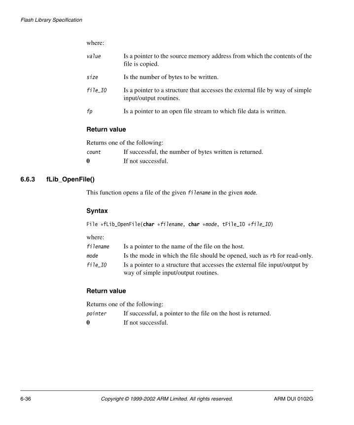
Flash Library Specification
where:
value Is a pointer to the source memory address from which the contents of the file is copied.
size Is the number of bytes to be written.
file_IO Is a pointer to a structure that accesses the external file by way of simple input/output routines.
fp Is a pointer to an open file stream to which file data is written.
Return value
Returns one of the following:
count If successful, the number of bytes written is returned.
0 If not successful.
6.6.3 fLib_OpenFile()
This function opens a file of the given filename in the given mode.
Syntax
File *fLib_OpenFile(char *filename, char *mode, tFile_IO *file_IO)
where:
filename Is a pointer to the name of the file on the host.
mode Is the mode in which the file should be opened, such as rb for read-only.
file_IO Is a pointer to a structure that accesses the external file input/output by way of simple input/output routines.
Return value
Returns one of the following:
pointer If successful, a pointer to the file on the host is returned.
0 If not successful.
6-36 Copyright © 1999-2002 ARM Limited. All rights reserved. ARM DUI 0102G

Flash Library Specification
6.6.4 fLib_CloseFile()
This function closes the specified file on the host.
Syntax
int fLib_CloseFile(File *file, tFile_Io *file_IO)
where:
file Is a pointer to the file on the host.
file_IO Is a pointer to a structure that accesses the external file I/O by simple I/O routines.
Return value
Returns one of the following:
0 If successful.
-1 If not successful.
6.6.5 fLib_ReadFileHead()
This function reads the file header, determines the file type, and sets fields in image from the data. The number of bytes read is returned in the field pointed to by size. The header is copied to the buffer already defined in image->head.
Syntax
unsigned int fLib_ReadFileHead(File *file, tImageInfo *image, unsigned int *size, tFile_IO *file_IO)
where:
file Is a pointer to the file on the host.
image Is a pointer to the image structure.
size Is a pointer to size of the data read from the host.
file_IO Is a pointer to a structure that accesses the external file I/O by simple I/O routines.
Return value
Returns one of the following:
filetype If the file type is known, it is returned as from ENUM_FILETYPE.
0 If the file type is unknown.
ARM DUI 0102G Copyright © 1999-2002 ARM Limited. All rights reserved. 6-37

Flash Library Specification
6.6.6 fLib_WriteFileHead()
This function writes the header pointed to by the image->footer to the specified file. The header is parsed and the writeFile routine pointer is updated.
Syntax
unsigned int fLib_WriteFileHead(File *file, tImageInfo *image, tFile_IO *file_IO)
where:
file Is a pointer to the file on the host.
image Is a pointer to the image structure.
file_IO Is a pointer to a structure that accesses the external file input/output by way of simple input/output routines.
Return value
Returns one of the following:
count If successful, the number of bytes written is returned.
0 If there is no header.
6.6.7 fLib_ReadFile()
This function reads (and converts) 32-bit words from the open file.
Syntax
unsigned int fLib_ReadFile(unsigned int *value, unsigned int size, tImageInfo *image, tFile_IO *file_IO)
where:
value Is a pointer to the memory address where the file data is copied.
size Is the number of bytes to be read.
image Is a pointer to the image structure.
file_IO Is a pointer to a structure that accesses the external file input/output by way of simple input/output routines.
Return value
Returns one of the following:
count If successful, the number of bytes read is returned.
0 If not successful.
6-38 Copyright © 1999-2002 ARM Limited. All rights reserved. ARM DUI 0102G
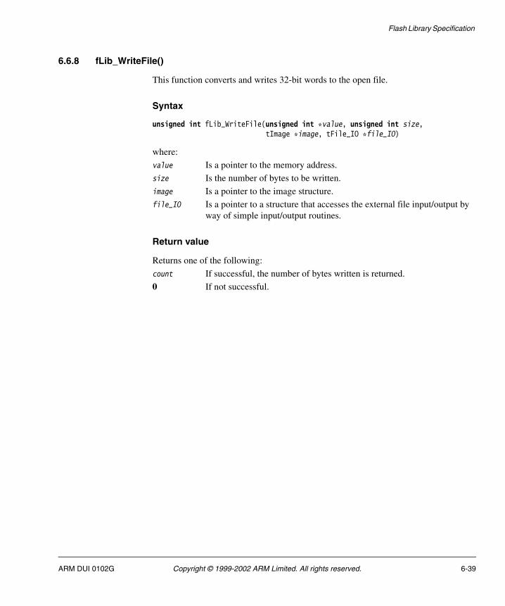
Flash Library Specification
6.6.8 fLib_WriteFile()
This function converts and writes 32-bit words to the open file.
Syntax
unsigned int fLib_WriteFile(unsigned int *value, unsigned int size, tImage *image, tFile_IO *file_IO)
where:
value Is a pointer to the memory address.
size Is the number of bytes to be written.
image Is a pointer to the image structure.
file_IO Is a pointer to a structure that accesses the external file input/output by way of simple input/output routines.
Return value
Returns one of the following:
count If successful, the number of bytes written is returned.
0 If not successful.
ARM DUI 0102G Copyright © 1999-2002 ARM Limited. All rights reserved. 6-39

Flash Library Specification
6.7 SIB functions
System Information Blocks (SIBs) provide nonvolatile storage for applications. The flash library can create a large block of memory called a SIB flash block that can then be used by various applications to create or access individual SIBs within the larger block. It is also possible for an application to ask for an entire SIB flash block if, for example, the application requires very large SIBs or if the SIBs must not be accidently modified by another applications.
The following functions are available to create and access SIBs:
• SIB_Open() on page 6-42
• SIB_Close() on page 6-43
• SIB_GetPointer() on page 6-43
• SIB_Copy() on page 6-44
• SIB_Program() on page 6-44
• SIB_GetSize() on page 6-45
• SIB_Verify() on page 6-45
• SIB_Erase() on page 6-46.
6.7.1 The SIB flash block
The SIB flash block contains multiple SIBs as shown in Figure 6-2 on page 6-41. The SIBs contained within the SIB flash block are application-dependent. The flash library defines how the SIB blocks are accessed but does not define the contents of the individual SIBs.
The size limit for SIB blocks is 512 bytes and the index limit (number of SIBs with the same name) is 64.
6-40 Copyright © 1999-2002 ARM Limited. All rights reserved. ARM DUI 0102G

Flash Library Specification
Figure 6-2 SIB flash block
Flash blocks containing SIBs must be identifiable. The SIB flash block footer contains a word that identifies the block as a SIB flash block. A SIB information block precedes the footer and contains additional information about the block. Table 6-6 describes the contents of the SIBInfo structure.
The SIB is defined as a C structure, as shown in Example 6-6 on page 6-42.
��������� ����) ���
7�����
-����!������
����8
-����!������
-����!������
-����!������
����9
����:
����;
'������ ����) ���
Table 6-6 SIBInfo structure
FieldSize (in bytes)
Value/usage
SIB unique number 4 Unique number for the SIB flash block (or blocks) for system reference.
SIB block extension 4 Pointer to the start of this SIB flash block (some SIBs require more than one flash block).
Label 16 Text label for identification of the SIB flash block. This will generally be the initializing system name.
Checksum 4 Checksum for this footer. The checksum is the word sum (with the carry wrapped into the least significant bit) and is stored as the inverse of the sum.
ARM DUI 0102G Copyright © 1999-2002 ARM Limited. All rights reserved. 6-41

Flash Library Specification
Example 6-6 SIBInfoType structure
typedef struct SIBInfoType{ unsigned32 SIB_number; /* Unique number of SIB Block */ unsigned32 SIB_Extension; /* Base of SIB flash block */ char Label[16]; /* String space for ownership string */ unsigned32 checksum; /* SIB Image checksum */
}tSIBInfo;
6.7.2 SIB_Open()
SIB_Open() scans flash for SIB blocks and indexes the SIBs in a linked list for faster access (an application might have multiple SIBs in different blocks). The application can then access the SIBs by their index. This routine uses the fLib_FindFlash(), fLib_OpenFlash(), and fLib_FindFooter() functions.
Syntax
int SIB_Open(char *idString, int *sibCount, int privFlag)
where:
idString Is provided by the application and is an identification string that will be used to locate existing blocks and mark new ones.
sibCount Is set to the number of SIBs found.
privFlag Is zero for common access or nonzero for private access. Private access means that the entire flash block is private.
Return value
Returns one of the following:
-1 If idString is already set.
0 If successful.
6-42 Copyright © 1999-2002 ARM Limited. All rights reserved. ARM DUI 0102G

Flash Library Specification
6.7.3 SIB_Close()
SIB_Close() frees SIB access.
Syntax
int SIB_Close(char *idString)
where:
idString Is provided by the application and is an identification string that is used to locate existing blocks and mark new ones.
Return value
Returns one of the following:
-1 If idString is already set.
0 If successful.
6.7.4 SIB_GetPointer()
SIB_GetPointer() gets the start address of SIB user data.
Syntax
int SIB_GetPointer(int sibIndex, void **dataBlock)
where:
sibIndex Is the index number of the SIB. The SIB indexes were identified by SIB_Open().
dataBlock Is set to the address of the SIB user data.
Return value
Returns one of the following:
-1 If not successful.
0 If successful. dataBlock is set to the address.
ARM DUI 0102G Copyright © 1999-2002 ARM Limited. All rights reserved. 6-43
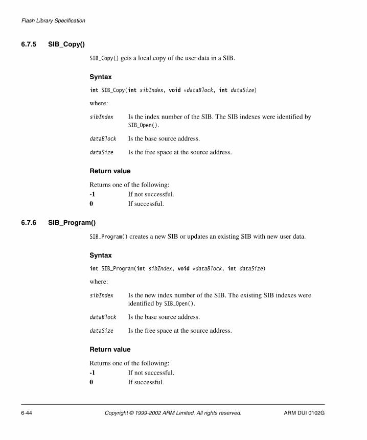
Flash Library Specification
6.7.5 SIB_Copy()
SIB_Copy() gets a local copy of the user data in a SIB.
Syntax
int SIB_Copy(int sibIndex, void *dataBlock, int dataSize)
where:
sibIndex Is the index number of the SIB. The SIB indexes were identified by SIB_Open().
dataBlock Is the base source address.
dataSize Is the free space at the source address.
Return value
Returns one of the following:
-1 If not successful.
0 If successful.
6.7.6 SIB_Program()
SIB_Program() creates a new SIB or updates an existing SIB with new user data.
Syntax
int SIB_Program(int sibIndex, void *dataBlock, int dataSize)
where:
sibIndex Is the new index number of the SIB. The existing SIB indexes were identified by SIB_Open().
dataBlock Is the base source address.
dataSize Is the free space at the source address.
Return value
Returns one of the following:
-1 If not successful.
0 If successful.
6-44 Copyright © 1999-2002 ARM Limited. All rights reserved. ARM DUI 0102G

Flash Library Specification
6.7.7 SIB_GetSize()
SIB_GetSize() gets the size of SIB data.
Syntax
int SIB_GetSize(int sibIndex, int *dataSize)
where:
sibIndex Is the index number of the SIB. The SIB indexes were identified by SIB_Open().
dataSize Is set to the size of the SIB.
Return value
Returns one of the following:
-1 If not successful.
0 If successful.
6.7.8 SIB_Verify()
SIB_Verify() verifies the SIB is intact by checking the signature and checksum.
Syntax
int SIB_Verify(int sibIndex)
where:
sibIndex Is the index number of the SIB. The SIB indexes were identified by SIB_Open().
Return value
Returns one of the following:
-1 If not successful.
0 If successful.
ARM DUI 0102G Copyright © 1999-2002 ARM Limited. All rights reserved. 6-45

Flash Library Specification
6.7.9 SIB_Erase()
SIB_Erase() erases the SIB.
Syntax
int SIB_Erase(int sibIndex)
where:
sibIndex Is the index number of the SIB. The SIB indexes were identified by SIB_Open(). The entry in active_sibs[sibIndex] is set to NULL.
Return value
Returns one of the following:
-1 If not successful.
0 If successful.
6-46 Copyright © 1999-2002 ARM Limited. All rights reserved. ARM DUI 0102G
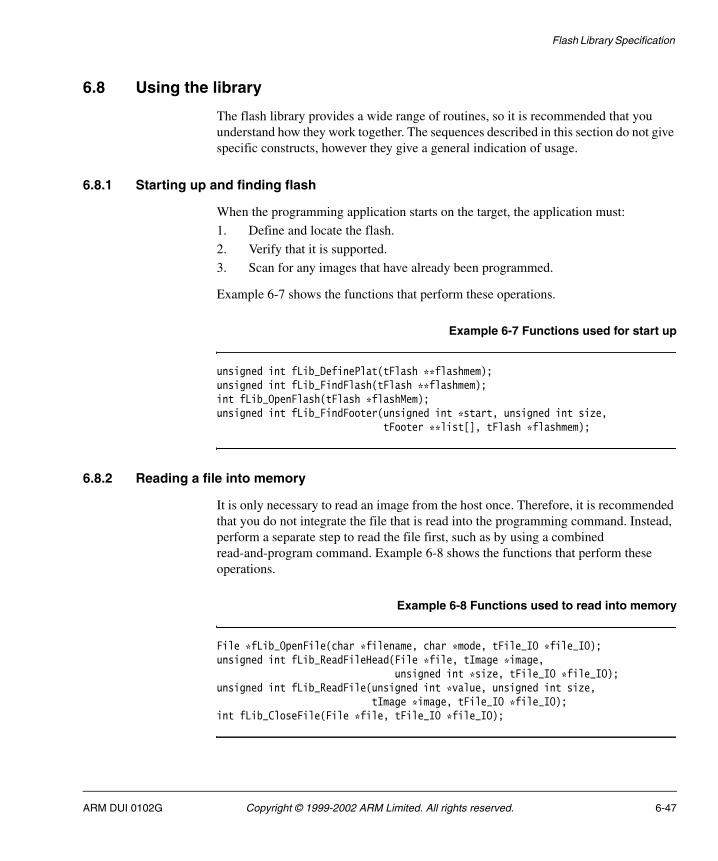
Flash Library Specification
6.8 Using the library
The flash library provides a wide range of routines, so it is recommended that you understand how they work together. The sequences described in this section do not give specific constructs, however they give a general indication of usage.
6.8.1 Starting up and finding flash
When the programming application starts on the target, the application must:
1. Define and locate the flash.
2. Verify that it is supported.
3. Scan for any images that have already been programmed.
Example 6-7 shows the functions that perform these operations.
Example 6-7 Functions used for start up
unsigned int fLib_DefinePlat(tFlash **flashmem);unsigned int fLib_FindFlash(tFlash **flashmem);int fLib_OpenFlash(tFlash *flashMem);unsigned int fLib_FindFooter(unsigned int *start, unsigned int size, tFooter **list[], tFlash *flashmem);
6.8.2 Reading a file into memory
It is only necessary to read an image from the host once. Therefore, it is recommended that you do not integrate the file that is read into the programming command. Instead, perform a separate step to read the file first, such as by using a combined read-and-program command. Example 6-8 shows the functions that perform these operations.
Example 6-8 Functions used to read into memory
File *fLib_OpenFile(char *filename, char *mode, tFile_IO *file_IO);unsigned int fLib_ReadFileHead(File *file, tImage *image, unsigned int *size, tFile_IO *file_IO);unsigned int fLib_ReadFile(unsigned int *value, unsigned int size, tImage *image, tFile_IO *file_IO);int fLib_CloseFile(File *file, tFile_IO *file_IO);
ARM DUI 0102G Copyright © 1999-2002 ARM Limited. All rights reserved. 6-47

Flash Library Specification
6.8.3 Preparing and programming an image
After the image is loaded into memory, space must be found for the image and the image footer has to be built before the image can be programmed. If an image is relocated into memory when executed, it can be programmed into any available flash space. If there is no room for the desired image in flash, an existing image will have to be deleted.
The image number must be checked to ensure that it is unique. If image numbers were not unique, there would be problems selecting one of the multiple images to execute. After the image is written, the footer should be rescanned to update the image list. (The image numbers are logical numbers and are not related to the order of the images in flash.) Example 6-9 shows the functions that perform these operations.
Example 6-9 Functions used for programming
int fLib_FindImage(tFooter **list, unsigned int imageNo, tFooter *foot, tFlash *flash);int fLib_GetEmptyFlash(tFooter **list, unsigned int *search_start, unsigned int *location, unsigned int empty, tFlash *flash);
or:
int fLib_GetEmptyArea(tFooter **list, unsigned int &location, unsigned int empty, tFlash *flash );int fLib_DeleteArea(unsigned int *address, unsigned int size, tFlash *flash);int fLib_BuildFooter(tFooter *foot, tFlash *flash);int fLib_ChecksumFooter(tFooter *footer, unsigned int *foot_sum, unsigned int *image_sum, tFlash *flash);int fLib_WriteImage(tImageInfo *image, tFlash *flash, unsigned int *current, tFooter *foot);
or:
int fLib_WriteArea(unsigned int *address, unsigned int *data, unsigned int size, tFlash *flashmem);tFooter* fLib_WriteFooter(tFooter *foot, tFlash *flash, unsigned int *foot_data, unsigned int *image_data);unsigned int fLib_FindFooter(unsigned int *start, unsigned int size, tFooter *list[], tFlash *flash);
6.8.4 Reading an image to a file
The process described in Preparing and programming an image can be reversed to produce a file on the host from a flash image. Example 6-10 on page 6-49 shows the functions that perform these operations.
6-48 Copyright © 1999-2002 ARM Limited. All rights reserved. ARM DUI 0102G

Flash Library Specification
Example 6-10 Functions used for reading
int fLib_FindImage(tFooter **list, unsigned int imageNo, tFooter *foot, tFlash *flash);int fLib_VerifyFooter(tFooter *foot, tFlash *flash );int fLib_ReadImage(tFooter *foot, tFlash *flash);int fLib_ChecksumImage(tFooter *footer, unsigned int *image_sum, tFlash *flash);tFILE *fLib_OpenFile(char *filename, char *mode, tFile_IO * file_IO);unsigned int fLib_WriteFileHead(tFILE *file, tImageInfo *image, tFile_IO * file_IO)fLib_WriteFile(unsigned32 *value, unsigned int size, tImageInfo *image, tFile_IO * file_IO);int fLib_CloseFile(tFILE *file, tFile_IO * file_IO);
6.8.5 Executing an image
This process is very similar to the image read, but instead of copying to memory and then to a file, the image is copied to memory only if specified, and then processor control is passed to the image. Example 6-11 shows the functions that perform these operations.
Example 6-11 Functions used for executing
int fLib_FindImage(tFooter **list, unsigned int imageNo, tFooter *foot, tFlash *flash);int fLib_VerifyFooter(tFooter *foot, tFlash *flash );int fLib_ReadImage(tFooter *foot, tFlash *flash);int fLib_ChecksumImage(tFooter *footer, unsigned int *image_sum, tFlash *flash);int fLib_ExecuteImage(tFooter *foot);
ARM DUI 0102G Copyright © 1999-2002 ARM Limited. All rights reserved. 6-49

Flash Library Specification
6-50 Copyright © 1999-2002 ARM Limited. All rights reserved. ARM DUI 0102G

Chapter 7 Using the ARM Flash Utilities
This chapter discusses the operation of utilities for accessing flash memory.
The ARM Flash Utility (AFU) provides functions for accessing the flash library as described in Chapter 6 Flash Library Specification.
The ARM Boot Flash Utility (BootFU) provides functions for programming the boot and FPGA areas of flash memory.
This chapter contains the following sections:
• About the AFU on page 7-2
• Starting the AFU on page 7-3
• AFU commands on page 7-4
• The Boot Flash Utility on page 7-20
• BootFU commands on page 7-22.
See also Chapter 3 ARM Boot Monitor and Chapter 6 Flash Library Specification for additional information about images in flash memory.
ARM DUI 0102G Copyright © 1999-2002 ARM Limited. All rights reserved. 7-1

Using the ARM Flash Utilities
7.1 About the AFU
The AFU is an application for manipulating and storing data within a system that uses the flash library. It is a target-based application designed to allow you to download code onto an ARM development system, maintaining the ARM Flash Library structure. This enables you to use ARM boot systems to run the code on the board.
The AFU can handle the following formats:
• ELF
• plain binary
• Motorola S-record format
• Intel hex format
• Compressed binary.
The AFU performs the following functions:
1. Reads the files from a host system.
2. Analyzes the required location (if applicable).
3. Writes the code image into the correct location in memory.
4. Strips the file header from the image and stores it immediately after the image. This allows full reconstruction of the file where possible.
5. Adds an image information block after any file header information to allow flash library-aware drivers to identify and run the code segments.
6. Stores the flash footer block at the subsequent block boundary to the image information block. This allows for quick image search routines.
7-2 Copyright © 1999-2002 ARM Limited. All rights reserved. ARM DUI 0102G
Using the ARM Flash Utilities
7.2 Starting the AFU
The AFU is designed to run within an ARM debug environment such as the ARM Multi-ICE server and the ARM eXtendable Debugger (AXD) environment. The target processor must have flash memory mapped to be noncacheable or configured to run without caches. To set up and run the AFU:
1. Start up a debug session for the board requiring flash download.
Note If you are using Angel instead of Multi-ICE, the Angel image must be present in
the development board and selected to run on reset.
2. Load the image afu.axf in the debugger.
3. Ensure the console window is active. If it is not, select Console from the View menu.
4. Run the code by pressing F5, or by typing go in the command window, or by clicking on the GO icon.
The console window appears in the foreground and becomes active, with the AFU header similar to the following:
ARM Firmware SuiteCopyright (c) ARM Ltd 1999-2000. All rights reserved.
ARM Flash UtilityProgram Version 1.0Date: 29 Jan 2000
The AFU scans for flash components and defaults to the device at the lowest address. After the flash device is selected, the AFU scans the flash for any images currently programmed.
The following prompt is displayed when the AFU is ready to accept user input:
AFU>
ARM DUI 0102G Copyright © 1999-2002 ARM Limited. All rights reserved. 7-3
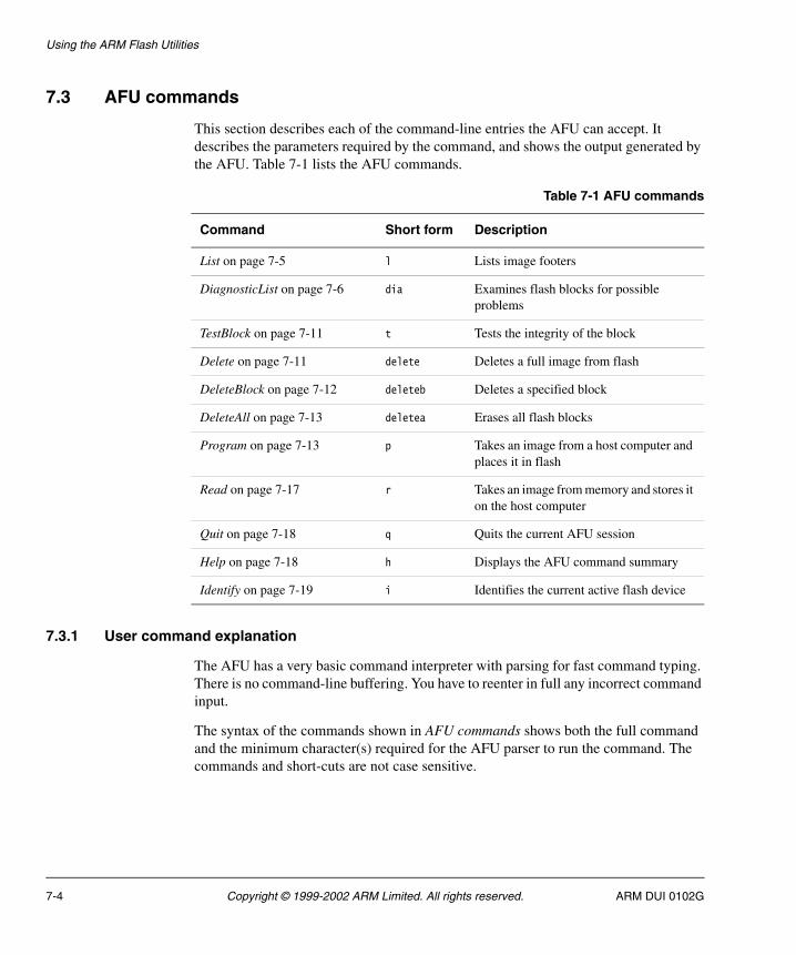
Using the ARM Flash Utilities
7.3 AFU commands
This section describes each of the command-line entries the AFU can accept. It describes the parameters required by the command, and shows the output generated by the AFU. Table 7-1 lists the AFU commands.
7.3.1 User command explanation
The AFU has a very basic command interpreter with parsing for fast command typing. There is no command-line buffering. You have to reenter in full any incorrect command input.
The syntax of the commands shown in AFU commands shows both the full command and the minimum character(s) required for the AFU parser to run the command. The commands and short-cuts are not case sensitive.
Table 7-1 AFU commands
Command Short form Description
List on page 7-5 l Lists image footers
DiagnosticList on page 7-6 dia Examines flash blocks for possible problems
TestBlock on page 7-11 t Tests the integrity of the block
Delete on page 7-11 delete Deletes a full image from flash
DeleteBlock on page 7-12 deleteb Deletes a specified block
DeleteAll on page 7-13 deletea Erases all flash blocks
Program on page 7-13 p Takes an image from a host computer and places it in flash
Read on page 7-17 r Takes an image from memory and stores it on the host computer
Quit on page 7-18 q Quits the current AFU session
Help on page 7-18 h Displays the AFU command summary
Identify on page 7-19 i Identifies the current active flash device
7-4 Copyright © 1999-2002 ARM Limited. All rights reserved. ARM DUI 0102G
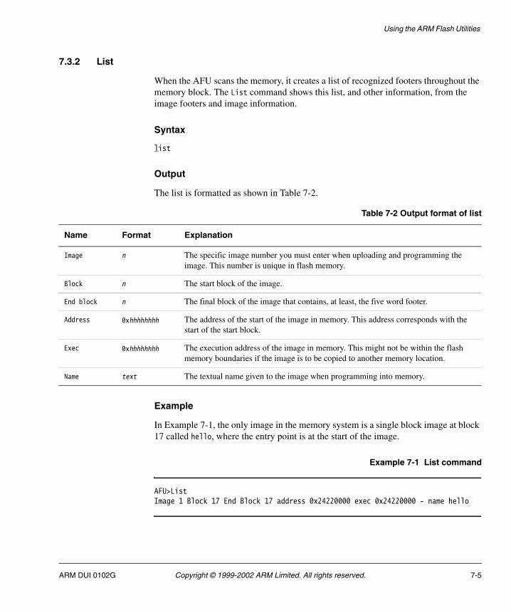
Using the ARM Flash Utilities
7.3.2 List
When the AFU scans the memory, it creates a list of recognized footers throughout the memory block. The List command shows this list, and other information, from the image footers and image information.
Syntax
list
Output
The list is formatted as shown in Table 7-2.
Example
In Example 7-1, the only image in the memory system is a single block image at block 17 called hello, where the entry point is at the start of the image.
Example 7-1 List command
AFU>ListImage 1 Block 17 End Block 17 address 0x24220000 exec 0x24220000 - name hello
Table 7-2 Output format of list
Name Format Explanation
Image n The specific image number you must enter when uploading and programming the image. This number is unique in flash memory.
Block n The start block of the image.
End block n The final block of the image that contains, at least, the five word footer.
Address 0xhhhhhhhh The address of the start of the image in memory. This address corresponds with the start of the start block.
Exec 0xhhhhhhhh The execution address of the image in memory. This might not be within the flash memory boundaries if the image is to be copied to another memory location.
Name text The textual name given to the image when programming into memory.
ARM DUI 0102G Copyright © 1999-2002 ARM Limited. All rights reserved. 7-5

Using the ARM Flash Utilities
7.3.3 DiagnosticList
This command has multiple functions to allow examination of the flash blocks to scan for possible problems. This command is rarely used in normal operation of the AFU.
Syntax
diagnosticlist {all|section bn|footer bn|dump bn}
where:
all Scans through every block in the current device. Outputs the usage of each block, as shown in Table 7-3.
If the image spans multiple blocks, each block is listed as used by the same image number and image name.
The AFU can only recognize blocks that have been programmed to conform to the flash library specification (see Image management on page 6-10).
The list will only show images that have the correct flash image footer. Any images not conforming to this are not shown, and the blocks occupied by these are marked as unused.
The DiagnosticList all command (and the following DiagnosticList section command) indents the used blocks to ensure that they can be noticed. This is useful when the list is rapidly scrolling down the console window.
Table 7-3 Output format of DiagnosticList all
Name Format Explanation
Block n The start block of the image.
Image number n The specific image number you must enter when uploading and programming the image. This number is unique in flash memory.
Type n The image type value, taken from the footer information.
Image text The textual name given to the image when programming into memory.
7-6 Copyright © 1999-2002 ARM Limited. All rights reserved. ARM DUI 0102G
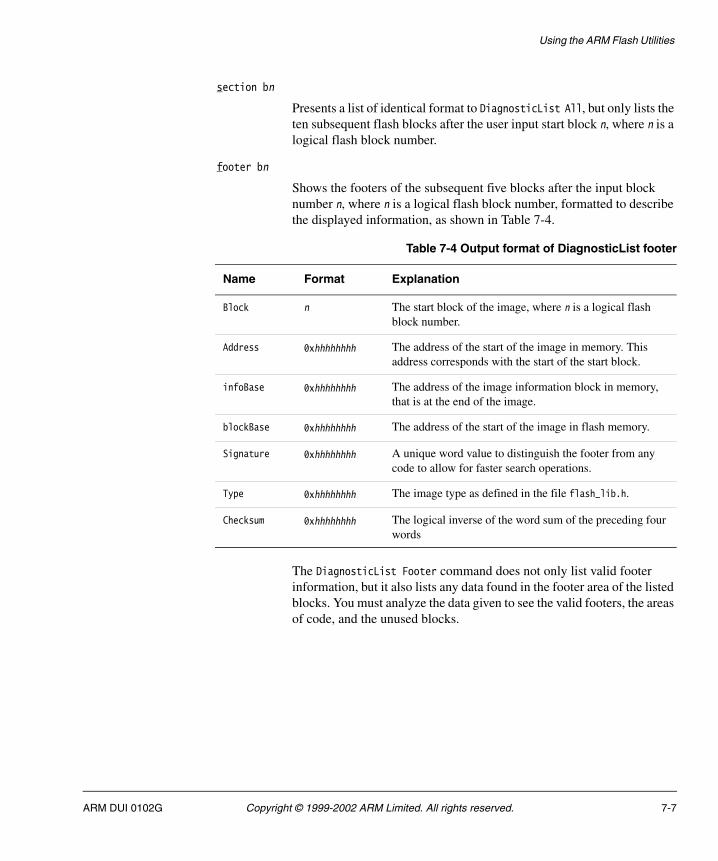
Using the ARM Flash Utilities
section bn
Presents a list of identical format to DiagnosticList All, but only lists the ten subsequent flash blocks after the user input start block n, where n is a logical flash block number.
footer bn
Shows the footers of the subsequent five blocks after the input block number n, where n is a logical flash block number, formatted to describe the displayed information, as shown in Table 7-4.
The DiagnosticList Footer command does not only list valid footer information, but it also lists any data found in the footer area of the listed blocks. You must analyze the data given to see the valid footers, the areas of code, and the unused blocks.
Table 7-4 Output format of DiagnosticList footer
Name Format Explanation
Block n The start block of the image, where n is a logical flash block number.
Address 0xhhhhhhhh The address of the start of the image in memory. This address corresponds with the start of the start block.
infoBase 0xhhhhhhhh The address of the image information block in memory, that is at the end of the image.
blockBase 0xhhhhhhhh The address of the start of the image in flash memory.
Signature 0xhhhhhhhh A unique word value to distinguish the footer from any code to allow for faster search operations.
Type 0xhhhhhhhh The image type as defined in the file flash_lib.h.
Checksum 0xhhhhhhhh The logical inverse of the word sum of the preceding four words
ARM DUI 0102G Copyright © 1999-2002 ARM Limited. All rights reserved. 7-7

Using the ARM Flash Utilities
dump bn Produces a hexadecimal dump of the first four words of the ten blocks following the input block number n (where n is a logical flash block number), as shown in Table 7-5. The DiagnosticList Dump command makes block-based (not image-based) selections, and displays the first four words of each block in the selected area starting at the input block.
Examples
The following examples (Example 7-2 to Example 7-5 on page 7-10) demonstrate usage of each DiagnosticList command.
Example 7-2 DiagnosticList all command
AFU>DiagnosticList AllBlock Number 0 unusedBlock 1 Image Number 1 type 1 Used by image hello_worldBlock 2 Image Number 2 type 1 Used by image dhrystoneBlock 3 Image Number 2 type 1 Used by image dhrystoneBlock Number 4 unusedBlock Number 5 unusedBlock Number 6 unusedBlock Number 7 unused...Block Number 255 unused
Table 7-5 Output format of DiagnosticList dump
Name Format Explanation
Block n The block number for the data being listed.
Address 0xhhhhhhhh The address of the first word being listed, that will correspond with the block number shown.
7-8 Copyright © 1999-2002 ARM Limited. All rights reserved. ARM DUI 0102G

Using the ARM Flash Utilities
Example 7-3 DiagnosticList footer command
AFU>DiagnosticList Footer B1Footer for Block 1 at Address 0x24020000infoBase : 0x2402330cblockBase : 0x24020000signature : 0xa00fff9ftype : 0x00000001checksum : 0x0beddde0
Footer for Block 2 at Address 0x24040000infoBase : 0x0a0000f0blockBase : 0xe3570078signature : 0x0a0000aetype : 0x00000001checksum : 0xe5940000
Footer for Block 3 at Address 0x24060000infoBase : 0x2404330cblockBase : 0x2404f000signature : 0xa00fff9ftype : 0x00000001checksum : 0x0be5fde0
Footer for Block 4 at Address 0x24080000infoBase : 0xffffffffblockBase : 0xffffffffsignature : 0xfffffffftype : 0xffffffffchecksum : 0xffffffff
Footer for Block 5 at Address 0x240a0000infoBase : 0xffffffffblockBase : 0xffffffffsignature : 0xfffffffftype : 0xffffffffchecksum : 0xffffffff
where:
Block 1 Is a correct footer because the signature is valid, and the infoBase and BlockBase are within the bounds of the image address (similar to the block address).
Block 2 Is either some random code of an image that spans two blocks (in this case), or a block that does not conform to the library specification.
ARM DUI 0102G Copyright © 1999-2002 ARM Limited. All rights reserved. 7-9
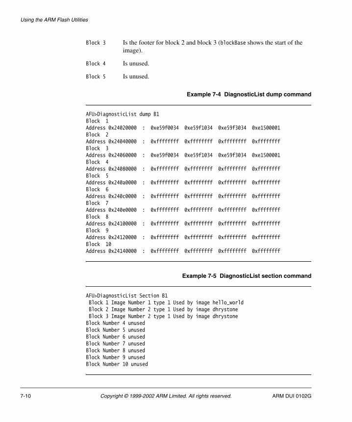
Using the ARM Flash Utilities
Block 3 Is the footer for block 2 and block 3 (blockBase shows the start of the image).
Block 4 Is unused.
Block 5 Is unused.
Example 7-4 DiagnosticList dump command
AFU>DiagnosticList dump B1Block 1 Address 0x24020000 : 0xe59f0034 0xe59f1034 0xe59f3034 0xe1500001Block 2 Address 0x24040000 : 0xffffffff 0xffffffff 0xffffffff 0xffffffffBlock 3Address 0x24060000 : 0xe59f0034 0xe59f1034 0xe59f3034 0xe1500001Block 4 Address 0x24080000 : 0xffffffff 0xffffffff 0xffffffff 0xffffffffBlock 5 Address 0x240a0000 : 0xffffffff 0xffffffff 0xffffffff 0xffffffffBlock 6 Address 0x240c0000 : 0xffffffff 0xffffffff 0xffffffff 0xffffffffBlock 7 Address 0x240e0000 : 0xffffffff 0xffffffff 0xffffffff 0xffffffffBlock 8 Address 0x24100000 : 0xffffffff 0xffffffff 0xffffffff 0xffffffffBlock 9 Address 0x24120000 : 0xffffffff 0xffffffff 0xffffffff 0xffffffffBlock 10 Address 0x24140000 : 0xffffffff 0xffffffff 0xffffffff 0xffffffff
Example 7-5 DiagnosticList section command
AFU>DiagnosticList Section B1Block 1 Image Number 1 type 1 Used by image hello_worldBlock 2 Image Number 2 type 1 Used by image dhrystoneBlock 3 Image Number 2 type 1 Used by image dhrystoneBlock Number 4 unusedBlock Number 5 unusedBlock Number 6 unusedBlock Number 7 unusedBlock Number 8 unusedBlock Number 9 unusedBlock Number 10 unused
7-10 Copyright © 1999-2002 ARM Limited. All rights reserved. ARM DUI 0102G
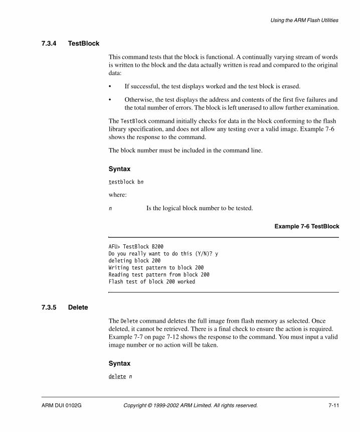
Using the ARM Flash Utilities
7.3.4 TestBlock
This command tests that the block is functional. A continually varying stream of words is written to the block and the data actually written is read and compared to the original data:
• If successful, the test displays worked and the test block is erased.
• Otherwise, the test displays the address and contents of the first five failures and the total number of errors. The block is left unerased to allow further examination.
The TestBlock command initially checks for data in the block conforming to the flash library specification, and does not allow any testing over a valid image. Example 7-6 shows the response to the command.
The block number must be included in the command line.
Syntax
testblock bn
where:
n Is the logical block number to be tested.
Example 7-6 TestBlock
AFU> TestBlock B200Do you really want to do this (Y/N)? ydeleting block 200Writing test pattern to block 200Reading test pattern from block 200Flash test of block 200 worked
7.3.5 Delete
The Delete command deletes the full image from flash memory as selected. Once deleted, it cannot be retrieved. There is a final check to ensure the action is required. Example 7-7 on page 7-12 shows the response to the command. You must input a valid image number or no action will be taken.
Syntax
delete n
ARM DUI 0102G Copyright © 1999-2002 ARM Limited. All rights reserved. 7-11

Using the ARM Flash Utilities
where:
n Is the image number of the full image to be deleted.
Example 7-7 Delete
AFU> Delete 4Do you really want to do this (Y/N)? yScanning Flash blocks for usage
Deleting flash image 4Scanning Flash blocks for usage
7.3.6 DeleteBlock
This command deletes the specified block input on the command line, irrespective of any AFU images in flash. Example 7-8 shows the response to the command. There is a final user check to ensure the action was intended.
Caution If used incorrectly, this command will damage images that span multiple blocks.
Syntax
deleteblock Bn
where:
n Is the number of the specific block to be deleted.
Example 7-8 DeleteBlock
AFU> DeleteBlock B17Do you really want to do this (Y/N)? yDelete flash block 17Scanning Flash blocks for usage
7-12 Copyright © 1999-2002 ARM Limited. All rights reserved. ARM DUI 0102G
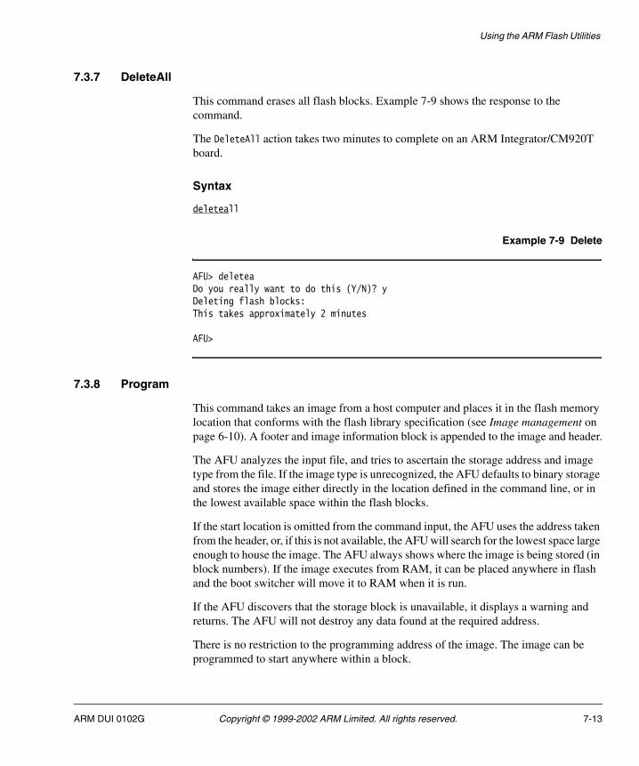
Using the ARM Flash Utilities
7.3.7 DeleteAll
This command erases all flash blocks. Example 7-9 shows the response to the command.
The DeleteAll action takes two minutes to complete on an ARM Integrator/CM920T board.
Syntax
deleteall
Example 7-9 Delete
AFU> deleteaDo you really want to do this (Y/N)? yDeleting flash blocks: This takes approximately 2 minutes
AFU>
7.3.8 Program
This command takes an image from a host computer and places it in the flash memory location that conforms with the flash library specification (see Image management on page 6-10). A footer and image information block is appended to the image and header.
The AFU analyzes the input file, and tries to ascertain the storage address and image type from the file. If the image type is unrecognized, the AFU defaults to binary storage and stores the image either directly in the location defined in the command line, or in the lowest available space within the flash blocks.
If the start location is omitted from the command input, the AFU uses the address taken from the header, or, if this is not available, the AFU will search for the lowest space large enough to house the image. The AFU always shows where the image is being stored (in block numbers). If the image executes from RAM, it can be placed anywhere in flash and the boot switcher will move it to RAM when it is run.
If the AFU discovers that the storage block is unavailable, it displays a warning and returns. The AFU will not destroy any data found at the required address.
There is no restriction to the programming address of the image. The image can be programmed to start anywhere within a block.
ARM DUI 0102G Copyright © 1999-2002 ARM Limited. All rights reserved. 7-13
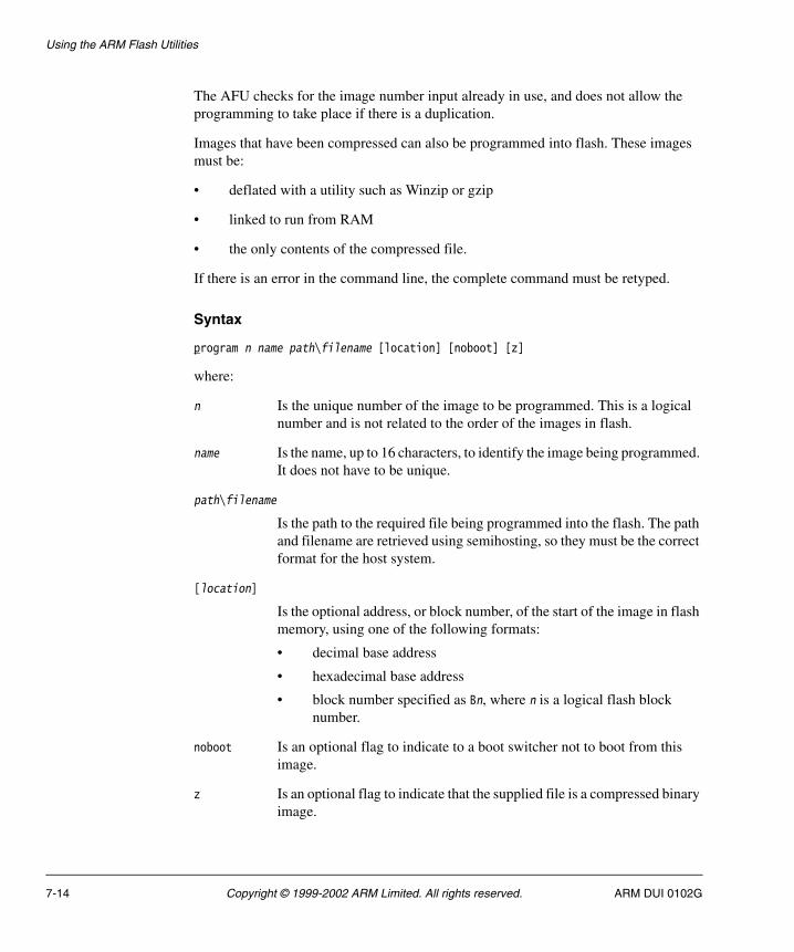
Using the ARM Flash Utilities
The AFU checks for the image number input already in use, and does not allow the programming to take place if there is a duplication.
Images that have been compressed can also be programmed into flash. These images must be:
• deflated with a utility such as Winzip or gzip
• linked to run from RAM
• the only contents of the compressed file.
If there is an error in the command line, the complete command must be retyped.
Syntax
program n name path\filename [location] [noboot] [z]
where:
n Is the unique number of the image to be programmed. This is a logical number and is not related to the order of the images in flash.
name Is the name, up to 16 characters, to identify the image being programmed. It does not have to be unique.
path\filename
Is the path to the required file being programmed into the flash. The path and filename are retrieved using semihosting, so they must be the correct format for the host system.
[location]
Is the optional address, or block number, of the start of the image in flash memory, using one of the following formats:
• decimal base address
• hexadecimal base address
• block number specified as Bn, where n is a logical flash block number.
noboot Is an optional flag to indicate to a boot switcher not to boot from this image.
z Is an optional flag to indicate that the supplied file is a compressed binary image.
7-14 Copyright © 1999-2002 ARM Limited. All rights reserved. ARM DUI 0102G
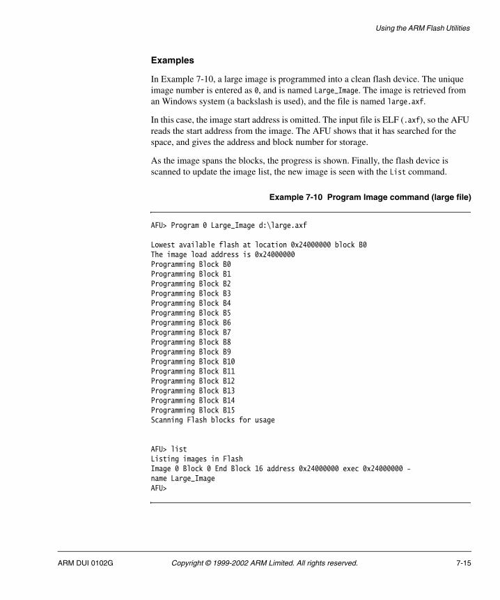
Using the ARM Flash Utilities
Examples
In Example 7-10, a large image is programmed into a clean flash device. The unique image number is entered as 0, and is named Large_Image. The image is retrieved from an Windows system (a backslash is used), and the file is named large.axf.
In this case, the image start address is omitted. The input file is ELF (.axf), so the AFU reads the start address from the image. The AFU shows that it has searched for the space, and gives the address and block number for storage.
As the image spans the blocks, the progress is shown. Finally, the flash device is scanned to update the image list, the new image is seen with the List command.
Example 7-10 Program Image command (large file)
AFU> Program 0 Large_Image d:\large.axf
Lowest available flash at location 0x24000000 block B0The image load address is 0x24000000Programming Block B0Programming Block B1Programming Block B2Programming Block B3Programming Block B4Programming Block B5Programming Block B6Programming Block B7Programming Block B8Programming Block B9Programming Block B10Programming Block B11Programming Block B12Programming Block B13Programming Block B14Programming Block B15Scanning Flash blocks for usage
AFU> listListing images in FlashImage 0 Block 0 End Block 16 address 0x24000000 exec 0x24000000 - name Large_ImageAFU>
ARM DUI 0102G Copyright © 1999-2002 ARM Limited. All rights reserved. 7-15

Using the ARM Flash Utilities
In Example 7-11, a small file is programmed into Block 18. The AFU does not search for available space because the location is specified in the command line. The area is, however, checked to ensure that it is empty. The image is a binary file so there is no alternative storage address in the header.
Example 7-11 Program Image command (small file)
AFU> Program 2 small_file d:\small.bin B18Programming Block B18Scanning Flash blocks for usage
AFU>
In Example 7-12, a compressed binary file is programmed into Block 25. The AFU will indicate that the image is compressed and prompt for the start address (where in RAM the image will be uncompressed to) and the execute address (where control is passed to when the image boots).
Example 7-12 Program Image command (compressed file)
AFU> Program 4 compressed_file d:\compressed.bin B25 zThis image will be marked for de-compression.Enter image load address [0x8000]:Enter image execute address [0x8000]:Programming Block B25Programming Block B26Programming Block B27Scanning Flash blocks for usage
AFU>
In Example 7-13 on page 7-17, shows a list command followed by an attempt to program the hello.axf image file to block 19.
The AFU prepares to insert the file at the correct execution address, but discovers that the block is being used (the block is part of Image 0). The AFU does not proceed with the download, but shows the error with the first block number involved. In this case, you must investigate the clash and decide what to do (you must either delete Image 0 or recompile hello.axf).
7-16 Copyright © 1999-2002 ARM Limited. All rights reserved. ARM DUI 0102G
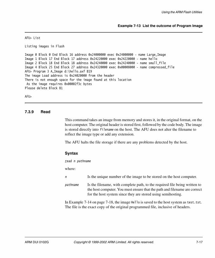
Using the ARM Flash Utilities
Example 7-13 List the outcome of Program Image
AFU> List
Listing images in Flash
Image 0 Block 0 End Block 16 address 0x24000000 exec 0x24000000 - name Large_ImageImage 1 Block 17 End Block 17 address 0x24220000 exec 0x24220000 - name helloImage 2 Block 18 End Block 18 address 0x24240000 exec 0x24240000 - name small_fileImage 4 Block 25 End Block 27 address 0x24320000 exec 0x00008000 - name compressed_fileAFU> Program 3 A_Image d:\hello.axf B19The image Load address is 0x24020000 from the headerThere is not enough space for the image found at this locationAs the image requires 0x00002f3c bytes
Please delete Block B1
AFU>
7.3.9 Read
This command takes an image from memory and stores it, in the original format, on the host computer. The original header is stored first, followed by the code body. The image is stored directly into filename on the host. The AFU does not alter the filename to reflect the image type or add any extension.
The AFU halts the file storage if there are any problems detected by the host.
Syntax
read n pathname
where:
n Is the unique number of the image to be stored on the host computer.
pathname Is the filename, with complete path, to the required file being written to the host computer. You must ensure that the path and filename are correct for the host system since they are stored using semihosting.
In Example 7-14 on page 7-18, the image Hello is saved to the host system as test.tst. The file is the exact copy of the original programmed file, inclusive of headers.
ARM DUI 0102G Copyright © 1999-2002 ARM Limited. All rights reserved. 7-17

Using the ARM Flash Utilities
Example 7-14 Read
AFU> r 1 d:\test.tstReading Block Number 17 of image hello
AFU>
7.3.10 Quit
This command quits the current AFU session. After you quit the session, you must restart the program.
Syntax
quit
7.3.11 Help
This command displays the AFU command summary.
Syntax
help
In addition to h, you can type ? to display the command summary.
Example 7-15 shows the output from the Help command.
Example 7-15 Help
AFU> HelpAFU command summary:
List - List images in flashDiagnosticList <All> | <Section Bn> | <Footer Bn> | <Dump Bn> Bn = B<Block No.>
- Lists information stored in the Flash by block, footer or block start dumpTestBlock B<block-number>
- Write a test pattern to a particular flash block except block 255 (SIB Block)Delete <image-number>
- Delete an image in flashDeleteBlock B<block-number>
- Deletes a block that appears not to be in an imageDeleteAll
7-18 Copyright © 1999-2002 ARM Limited. All rights reserved. ARM DUI 0102G
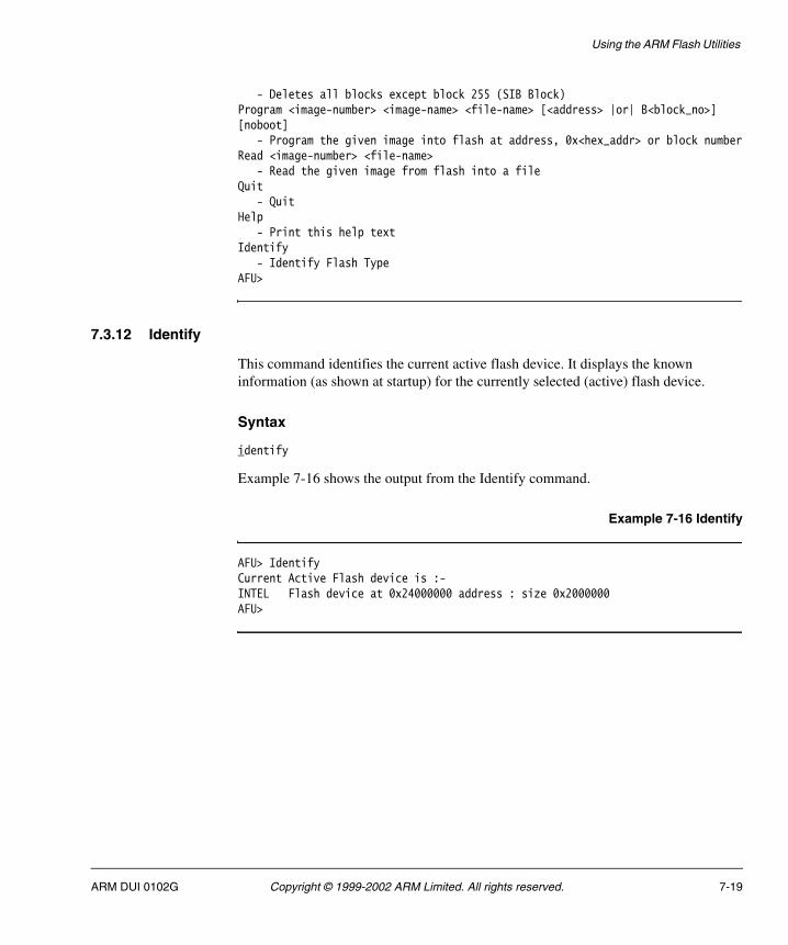
Using the ARM Flash Utilities
- Deletes all blocks except block 255 (SIB Block)Program <image-number> <image-name> <file-name> [<address> |or| B<block_no>][noboot]
- Program the given image into flash at address, 0x<hex_addr> or block numberRead <image-number> <file-name>
- Read the given image from flash into a fileQuit
- QuitHelp
- Print this help textIdentify
- Identify Flash TypeAFU>
7.3.12 Identify
This command identifies the current active flash device. It displays the known information (as shown at startup) for the currently selected (active) flash device.
Syntax
identify
Example 7-16 shows the output from the Identify command.
Example 7-16 Identify
AFU> IdentifyCurrent Active Flash device is :-INTEL Flash device at 0x24000000 address : size 0x2000000 AFU>
ARM DUI 0102G Copyright © 1999-2002 ARM Limited. All rights reserved. 7-19

Using the ARM Flash Utilities
7.4 The Boot Flash Utility
The ARM Boot Flash Utility (BootFU) allows you to modify the specific boot flash sector on the system.
Caution The Boot Flash on the Integrator board contains important system setup data (the FPGA initialization data) as well as the boot monitor and switcher code.
Modification of the boot flash on the Integrator board always involves a complete boot flash chip erase prior to programming. If the flash is programmed with incorrect data it halts operation of the board. This is generally a catastrophic failure.
If a problem is found with the downloaded data, the BootFU options can halt programming prior to erasing the flash device. This gives you a chance to backup the flash information.
In addition to diagnostic functions, BootFU can:
• update the whole boot area from an Intel hex file containing boot monitor and FPGA data
• update only the boot monitor area
• update only the FPGA area.
7.4.1 File Types
BootFU accepts ELF (.axf), binary (.bin), and Motorola M32 S-record (.mcs or .m32) files for the downloaded image, although the filename and extension is not important because the BootFU code checks the file type from the data records transferred.
7-20 Copyright © 1999-2002 ARM Limited. All rights reserved. ARM DUI 0102G
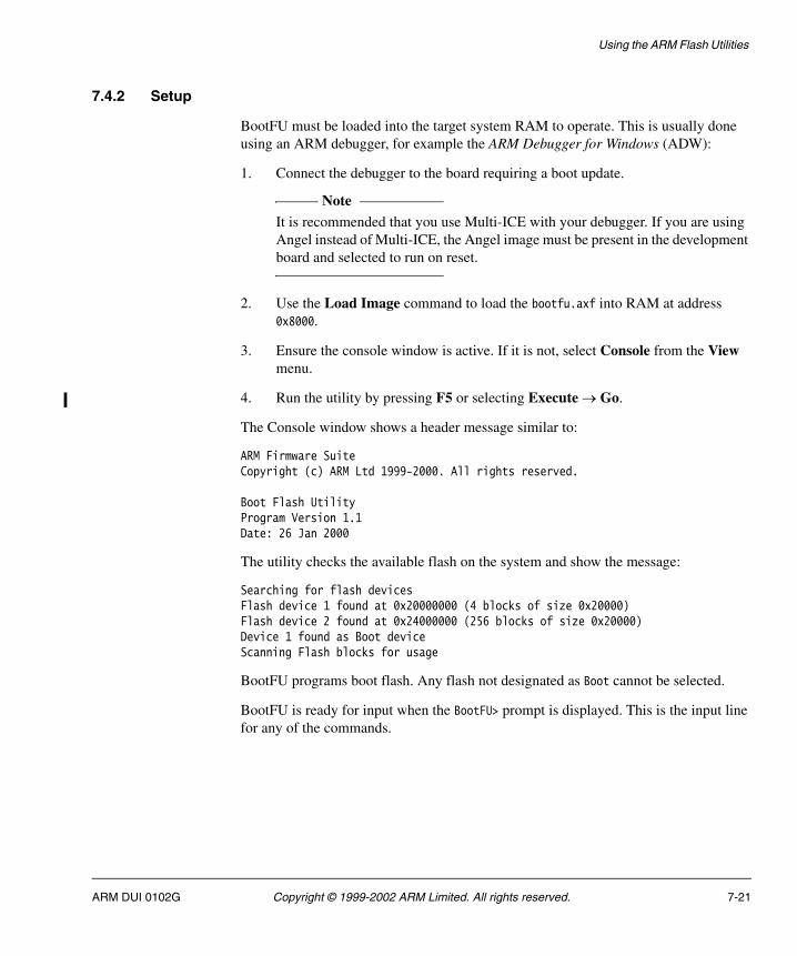
Using the ARM Flash Utilities
7.4.2 Setup
BootFU must be loaded into the target system RAM to operate. This is usually done using an ARM debugger, for example the ARM Debugger for Windows (ADW):
1. Connect the debugger to the board requiring a boot update.
Note It is recommended that you use Multi-ICE with your debugger. If you are using
Angel instead of Multi-ICE, the Angel image must be present in the development board and selected to run on reset.
2. Use the Load Image command to load the bootfu.axf into RAM at address 0x8000.
3. Ensure the console window is active. If it is not, select Console from the View menu.
4. Run the utility by pressing F5 or selecting Execute → Go.
The Console window shows a header message similar to:
ARM Firmware SuiteCopyright (c) ARM Ltd 1999-2000. All rights reserved.
Boot Flash UtilityProgram Version 1.1Date: 26 Jan 2000
The utility checks the available flash on the system and show the message:
Searching for flash devicesFlash device 1 found at 0x20000000 (4 blocks of size 0x20000)Flash device 2 found at 0x24000000 (256 blocks of size 0x20000)Device 1 found as Boot device Scanning Flash blocks for usage
BootFU programs boot flash. Any flash not designated as Boot cannot be selected.
BootFU is ready for input when the BootFU> prompt is displayed. This is the input line for any of the commands.
ARM DUI 0102G Copyright © 1999-2002 ARM Limited. All rights reserved. 7-21
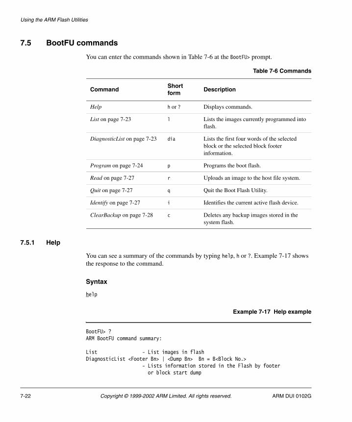
Using the ARM Flash Utilities
7.5 BootFU commands
You can enter the commands shown in Table 7-6 at the BootFU> prompt.
7.5.1 Help
You can see a summary of the commands by typing help, h or ?. Example 7-17 shows the response to the command.
Syntax
help
Example 7-17 Help example
BootFU> ?ARM BootFU command summary:
List - List images in flashDiagnosticList <Footer Bn> | <Dump Bn> Bn = B<Block No.> - Lists information stored in the Flash by footer or block start dump
Table 7-6 Commands
CommandShort form
Description
Help h or ? Displays commands.
List on page 7-23 l Lists the images currently programmed into flash.
DiagnosticList on page 7-23 dia Lists the first four words of the selected block or the selected block footer information.
Program on page 7-24 p Programs the boot flash.
Read on page 7-27 r Uploads an image to the host file system.
Quit on page 7-27 q Quit the Boot Flash Utility.
Identify on page 7-27 i Identifies the current active flash device.
ClearBackup on page 7-28 c Deletes any backup images stored in the system flash.
7-22 Copyright © 1999-2002 ARM Limited. All rights reserved. ARM DUI 0102G

Using the ARM Flash Utilities
Program [i<image-number>] [*<image-name>] <file-name> [b<block_no>] [!] - Program the given image into flash block number - ! means no boot backupRead <image-number> <file-name> - Read the given image from flash into a fileQuit - QuitHelp - Print this help textIdentify - Identify Flash TypeClearBackup - Removes any Boot backup images from the main system flash
7.5.2 List
This command lists the images currently programmed into flash. If the image has a header, its information is displayed. If there is only unstructured data in the flash, it is displayed as unformatted data.
Syntax
list
Example 7-18 List Example
BootFU> list Block 0 Image Number 4280910 type 1 Used by image Boot_Monitor Block 1 is unused Block 2 Has unformatted data Block 3 Has unformatted data
In Example 7-18, the boot monitor has footer information applied to it as Image1. The FPGA setup data in the upper two blocks never has footer information applied. If the entire boot area is programmed from Intel hex files, there is no footer information. The listing only shows the programmed blocks as unformatted data.
7.5.3 DiagnosticList
The DiagnosticList command allows the listing of the first four words of the selected block or the selected block footer information. Example 7-19 on page 7-24 shows the response.
Syntax
diagnosticList f bn|d bn
ARM DUI 0102G Copyright © 1999-2002 ARM Limited. All rights reserved. 7-23
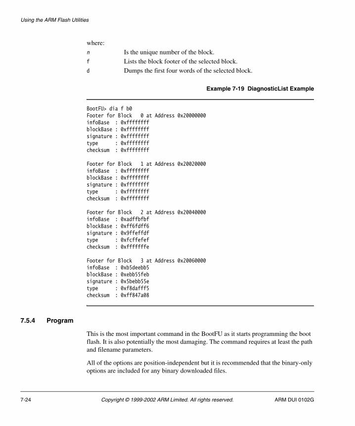
Using the ARM Flash Utilities
where:
n Is the unique number of the block.
f Lists the block footer of the selected block.
d Dumps the first four words of the selected block.
Example 7-19 DiagnosticList Example
BootFU> dia f b0Footer for Block 0 at Address 0x20000000infoBase : 0xffffffffblockBase : 0xffffffffsignature : 0xfffffffftype : 0xffffffffchecksum : 0xffffffff
Footer for Block 1 at Address 0x20020000infoBase : 0xffffffffblockBase : 0xffffffffsignature : 0xfffffffftype : 0xffffffffchecksum : 0xffffffff
Footer for Block 2 at Address 0x20040000infoBase : 0xadffbfbfblockBase : 0xff6fdff6signature : 0x9ffeffdftype : 0xfcffefefchecksum : 0xfffffffe
Footer for Block 3 at Address 0x20060000infoBase : 0xb5deebb5blockBase : 0xebb55febsignature : 0x5bebb55etype : 0xf8dafff5checksum : 0xff847a08
7.5.4 Program
This is the most important command in the BootFU as it starts programming the boot flash. It is also potentially the most damaging. The command requires at least the path and filename parameters.
All of the options are position-independent but it is recommended that the binary-only options are included for any binary downloaded files.
7-24 Copyright © 1999-2002 ARM Limited. All rights reserved. ARM DUI 0102G

Using the ARM Flash Utilities
Syntax
program path_and_file [bblnum] [iimnum] [*string] [!]
where:
path_and_file
Is the full path to the file and consists of:
• the path
• the file separator used on the host operating system
• the name of the file.
blnum Is the block number to be programmed.
imnum Is the image number for the footer information for binary files.
Caution Boot monitor, and only boot monitor, must be programmed with image
number 4280910 in order for it to identify itself.
string Is the name of the image for the footer information for binary files.
! Specifies not to backup the boot area (for systems such as Integrator that have only a single block of boot flash).
Note On systems with multiple blocks of boot flash, this command is not
supported as there is no benefit in backing up the rest of the device.
Examples
Example 7-20 shows a complete boot area program from an Intel hex file.
Example 7-20 Program boot area
BootFU> program d:\test.mcs****************************************************************** WARNING: re-programming the Boot Flash can cause the system ** to cease operation - if the images are corrupted or ** incorrect. Are you sure you wish to continue? ******************************************************************
Do you really want to do this (y/N)? yBacking up boot imageBoot Image backed up to board flashDeleting Boot Flash area
ARM DUI 0102G Copyright © 1999-2002 ARM Limited. All rights reserved. 7-25

Using the ARM Flash Utilities
Decoding and Writing .mcs type fileScanning Flash blocks for usageBootFU>
In Example 7-21 the boot monitor code in block 0 is being updated. The system FPGA data is restored from the backup image stored in the main system flash.
Example 7-21 Program block 0
BootFU> program i4280910 *Boot_Monitor d:\boot.axf b0****************************************************************** WARNING: re-programming the Boot Flash can cause the system ** to cease operation - if the images are corrupted or ** incorrect. Are you sure you wish to continue? ******************************************************************
Do you really want to do this (y/N)? yBacking up boot imageBoot Image backed up to board flashDeleting Boot Flash Area Writing Binary type fileProgramming Block B0Restoring unprogrammed boot flash from BackupDeleting BackupScanning Flash blocks for usageBootFU>
BootFU operation includes checks to ensure that the correct data is used to update the image.
The standard operation of BootFU is usually either:
program path\filename
This is for the complete update of the boot flash.
program path\filename bn in *string
For updates, the identifier parameter is optional for image recognition of binary files.
The no backup option (!) is not recommended. It reduces the program time but it is not as safe as backing up the data in the system flash.
7-26 Copyright © 1999-2002 ARM Limited. All rights reserved. ARM DUI 0102G
Using the ARM Flash Utilities
7.5.5 Read
This command allows an image (specifying the image number as inumber) or a block (specifying the block number as bnumber) to be uploaded to the host file system. You must add the path and filename parameters to the command. If block 0 is requested the entire boot device is uploaded and saved. The output file is a pure binary file.
Syntax
read in| bn path_and_file
where:
n Is the unique number of the image or block.
i Reads the selected image.
b Reads the selected block.
path_and_file
Is the full path to the file and consists of:
• the path
• the file separator used on the host operating system
• the name of the file.
7.5.6 Quit
This command quits the BootFU.
Syntax
quit
7.5.7 Identify
This command identifies the current active flash device. This displays the flash type (boot), device physical base address, and device size in bytes.
Syntax
identify
ARM DUI 0102G Copyright © 1999-2002 ARM Limited. All rights reserved. 7-27
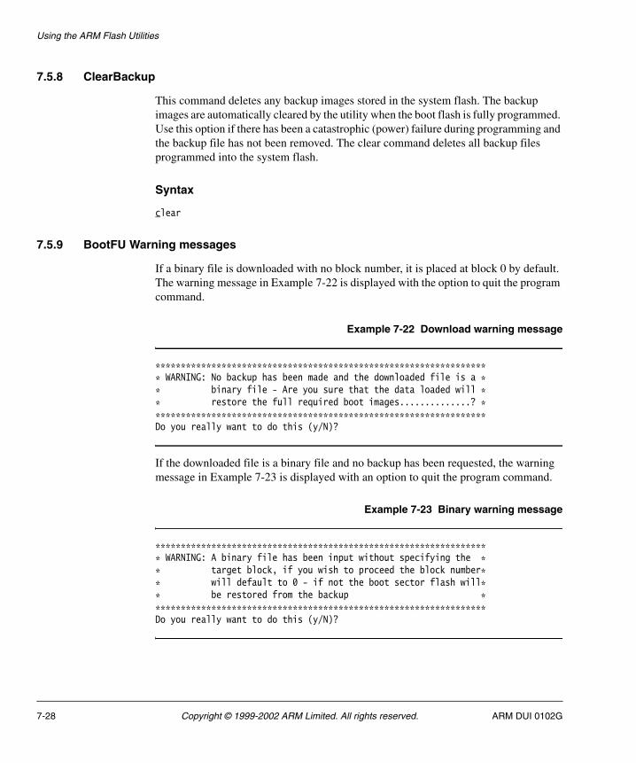
Using the ARM Flash Utilities
7.5.8 ClearBackup
This command deletes any backup images stored in the system flash. The backup images are automatically cleared by the utility when the boot flash is fully programmed. Use this option if there has been a catastrophic (power) failure during programming and the backup file has not been removed. The clear command deletes all backup files programmed into the system flash.
Syntax
clear
7.5.9 BootFU Warning messages
If a binary file is downloaded with no block number, it is placed at block 0 by default. The warning message in Example 7-22 is displayed with the option to quit the program command.
Example 7-22 Download warning message
****************************************************************** WARNING: No backup has been made and the downloaded file is a ** binary file - Are you sure that the data loaded will ** restore the full required boot images..............? ******************************************************************Do you really want to do this (y/N)?
If the downloaded file is a binary file and no backup has been requested, the warning message in Example 7-23 is displayed with an option to quit the program command.
Example 7-23 Binary warning message
****************************************************************** WARNING: A binary file has been input without specifying the ** target block, if you wish to proceed the block number** will default to 0 - if not the boot sector flash will** be restored from the backup ******************************************************************Do you really want to do this (y/N)?
7-28 Copyright © 1999-2002 ARM Limited. All rights reserved. ARM DUI 0102G

Chapter 8 PCI Management Library
This chapter describes the Peripheral Component Interconnect (PCI) library and how you can use it to configure PCI subsystems. Its contains the following sections:
• About PCI on page 8-2
• PCI configuration on page 8-4
• The PCI library on page 8-8
• PCI library functions and definitions on page 8-14
• About µHAL PCI extensions on page 8-16
• µHAL PCI function descriptions on page 8-17
• Example PCI device driver on page 8-23.
ARM DUI 0102G Copyright © 1999-2002 ARM Limited. All rights reserved. 8-1

PCI Management Library
8.1 About PCI
This section provides an introduction to the PCI terminology used in this chapter. Figure 8-1 shows the major components of an example PCI system.
Figure 8-1 An example PCI system
HostCPU
PCIHost
BridgeVideo
PCI-PCIBridge
PCI-ISABridge
Hostmemory
Ethernet SCSI
Host bus
PCI bus 0
PCI bus 1(e.g. CompactPCI)
Super I/Ocontroller
ISA bus
Upstream
Downstream
Upstream
Downstream
8-2 Copyright © 1999-2002 ARM Limited. All rights reserved. ARM DUI 0102G
PCI Management Library
The system features illustrated in Figure 8-1 on page 8-2 are:
Host bus In this system, the CPU and host memory reside on the host bus.
Host bridge This is a device that allows transactions between the host bus and PCI bus to take place. These typically support a variety of reads and writes in both directions and might incorporate FIFOs to support writes in both directions. The types of transactions supported by the bridge are configurable.
In the case of the ARM Integrator, there is an additional bridge between the host bus and system bus to which the processors and memory connect. However, from the point of view of the PCI functions, this bridge is transparent.
PCI-PCI bridge The electrical loading on a PCI bus is limited and there is a limited number of devices that can be connected. To overcome this, multiple PCI buses can be used. The different buses are connected through PCI-PCI bridges. In this system, the PCI-PCI bridge connects between bus 0 (used to access fast on-board peripherals) and bus 1 (in this case is a CompactPCI backplane bus).
All devices connected to the PCI buses including bridges are uniquely identified by the number of the bus to which they are attached and the slot number they occupy on that bus. Typically, the CPU or host bridge is in slot 0.
In the case of a multi-function PCI device, such as a combined sound and video device, each function is treated as a different device. In order to uniquely address a PCI device, specify the bus, slot, and function numbers for that device.
PCI-ISA bridge The PCI-ISA bridge provides support for legacy devices. In this example, a super input/output controller is used. The PCI-ISA bridge translates PCI address cycles into ISA address cycles so that the CPU can access the legacy devices on the ISA bus.
Primary bus In this system, PCI bus 0 is the primary (or upstream) bus for the PCI-PCI bus. The primary bus for a particular bridge is the bus nearer to the host CPU that controls the system.
Secondary bus In this system, PCI bus 1 is the secondary (or downstream) bus for the PCI-PCI bridge.
The bus numbering is important. During initialization the bus numbers are assigned by the CPU. However, device drivers do not differentiate when communicating with devices on different PCI buses.
ARM DUI 0102G Copyright © 1999-2002 ARM Limited. All rights reserved. 8-3
PCI Management Library
8.2 PCI configuration
This section provides a brief software-biased overview of PCI configuration. The PCI library contains software to fully configure PCI subsystems. This includes:
• scanning and identifying PCI devices on local and bridged PCI buses
• assigning device resources in PCI memory and I/O space
• allocating interrupt numbers
• numbering the PCI-PCI bridges.
The PCI library uses services exported from the µHAL library to access the PCI subsystem in a generic way (see About µHAL PCI extensions on page 8-16).
The PCI component of the firmware base level contains the PCI library and example applications. Source code is provided for the scanpci application that initializes the PCI subsystem and displays its topology. A sample device driver is also provided that initializes the PCI bus and assigns interrupt handlers (see Example PCI device driver on page 8-23).
Caution If two VGA adaptors are fitted to the PCI bus, the library assigns them the same addresses. This could cause incorrect operation or damage to the adaptors.
8.2.1 PCI address spaces
There are three PCI address spaces:
• configuration space
• I/O space
• memory space.
Configuration space
Each PCI device in the system has a 256-byte header in PCI configuration space. The contents of this header are specified by the PCI standard and defines, among other things:
• the device type
• the device manufacturer
• how much PCI I/O space the device requires
• how much PCI memory address space the device requires.
8-4 Copyright © 1999-2002 ARM Limited. All rights reserved. ARM DUI 0102G
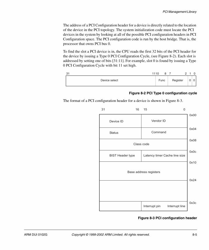
PCI Management Library
The address of a PCI Configuration header for a device is directly related to the location of the device in the PCI topology. The system initialization code must locate the PCI devices in the system by looking at all of the possible PCI configuration headers in PCI Configuration space. The PCI configuration code is run by the host bridge. That is, the processor that owns PCI bus 0.
To find the slot a PCI device is in, the CPU reads the first 32 bits of the PCI header for the device by issuing a Type 0 PCI Configuration Cycle, (see Figure 8-2). Each slot is addressed by setting one of bits [31:11]. For example, slot 0 is found by issuing a Type 0 PCI Configuration Cycle with bit 11 set high.
Figure 8-2 PCI Type 0 configuration cycle
The format of a PCI configuration header for a device is shown in Figure 8-3.
Figure 8-3 PCI configuration header
Device select Func Register
31 1110 8 7 2 1 0
00
89 9< 9= >
��������� ?��������
����#� ������
��������
�����"���������� 1������������ ����� ������+�
���������������!������
������#������ ������#��� ���>8�
>:;
>9>
>>�
>>@
>>;
>>>
ARM DUI 0102G Copyright © 1999-2002 ARM Limited. All rights reserved. 8-5

PCI Management Library
The device and vendor identifiers are unique and completely identify the maker of the PCI device and its type. In addition, the class code identifies the generic type of the device (for example, video device). The Base Address Registers are used to request and grant space in PCI I/O or memory spaces.
I/O space
PCI I/O space is used for small amounts of memory that the device makes accessible to the main processor. Typically, this contains registers within the device.
Memory space
PCI memory space is used for much larger amounts of memory. Video devices often use large amounts of PCI memory space.
8.2.2 PCI-PCI bridges
The PCI initialization code must recognize PCI-PCI bridges and configure them so that addresses and data are passed between the upstream and downstream sides.
Except for the required initialization code, a PCI-PCI bridge is transparent to the PCI devices in the system. PCI I/O and PCI Memory address spaces do not have a hierarchy. Software running on the host bridge accesses a device without knowing whether the device’s addresses were assigned to PCI I/O and PCI Memory.
The PCI configuration code uses a Type 1 PCI Configuration Cycle for addressing PCI devices that are not on the primary bus (see Figure 8-4).
Figure 8-4 PCI Type 1 configuration cycle
The Type 1 Configuration cycle includes the bus number within the address.
89 :; :8 9< 9= 99 9> @ A : 9 >
�������� �#� ��������� ��� 7#�� ��!����� > 9
8-6 Copyright © 1999-2002 ARM Limited. All rights reserved. ARM DUI 0102G
PCI Management Library
The PCI-PCI bridges (between the host bridge and the final PCI bus to which the target device is attached) are responsible for passing the Type 1 cycle along to the next bus. The algorithm for this mechanism is:
• If the configuration cycle is for a device on the downstream bus, translate it to a Type 0 cycle.
• If the Configuration cycle is for a device beyond the downstream bus, pass it on to the next bridge unchanged (as a Type 1 cycle).
This means that the buses must be numbered in a particular order. When the type 1 PCI configuration cycle reaches its destination bus, the final PCI-PCI bridge translates it into a Type 0 configuration cycle.
ARM DUI 0102G Copyright © 1999-2002 ARM Limited. All rights reserved. 8-7
PCI Management Library
8.3 The PCI library
The PCI library code has three main functions:
• to initialize the PCI subsystem, that is, to identify the PCI devices and buses in the system and then assign them resources
• to locate PCI devices by device drivers
• to allow the PCI device drivers to control their devices.
8.3.1 Initializing the PCI subsystem
This is carried out in three phases:
1. Perform any host bridge initialization (using the system specific µHAL support function).
2. Scan the local PCI bus for PCI devices. Some of the PCI devices found are PCI-PCI bridges and, in this case, the PCI initialization code also scans for PCI devices downstream of the PCI-PCI bridge. In doing this the code must number the PCI buses.
3. Assign resources to the PCI devices. These resources are:
• areas of PCI I/O and PCI memory. PCI devices must be granted addresses in PCI I/O and PCI Memory space and those addresses must be enabled.
• interrupt numbers. PCI devices must be given relevant interrupt numbers that are meaningful to the device drivers in the application or operating system.
8-8 Copyright © 1999-2002 ARM Limited. All rights reserved. ARM DUI 0102G

PCI Management Library
8.3.2 Data structures
As the initialization code locates PCI devices, it builds a PCIDevice data structure describing each one. These each have the format shown in Example 8-1.
Example 8-1 Building data structures
/* A PCI device, the PCI configuration code builds a list of PCI devices */typedef struct PCIDevice { struct PCIDevice *next ; // next PCI device in the system (all buses) struct PCIDevice *sibling ; // next device on this bus struct PCIDevice *parent ; // this device's parent device Flagsstruct {unsigned int bridge : 1 ; // This is a PCI-PCI bridge deviceunsigned int spare : 15 ;} flags ;// This part of the structure is only relevant if this is a PCI-PCI bridgestruct {struct PCIDevice *children ; // pointer to child devices of this PCI-PCI bridge unsigned char number ; // This bus's number unsigned char primary ; // number of primary bridge unsigned char secondary ; // number of secondary bridge unsigned char subordinate ; // number of subordinate buses} bridge ;// Vendor/Device is a unique key across all PCI devices.unsigned short vendor ;unsigned short device ;// PCI Configuration space addressing information for this deviceunsigned char bus ; unsigned char slot ;unsigned char func ;} PCIDevice_t ;
The list is hierarchical, reflecting the PCI topology of the system. If the PCI device is a PCI bridge, its children pointer points at the first PCI device found downstream of it. Each PCI device is on two lists:
PCIroot Points at the host bridge
PCIDeviceList Points at all of the PCI devices in the system.
To find all of the PCI devices in the system, follow the address in PCIDeviceList through the next pointer of each PCIDevice structure.
ARM DUI 0102G Copyright © 1999-2002 ARM Limited. All rights reserved. 8-9
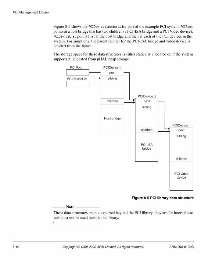
PCI Management Library
Figure 8-5 shows the PCIDevice structures for part of the example PCI system. PCIRoot points at a host bridge that has two children (a PCI-ISA bridge and a PCI Video device). PCIDeviceList points first at the host bridge and then at each of the PCI devices in the system. For simplicity, the parent pointer for the PCI-ISA bridge and video device is omitted from the figure.
The storage space for these data structures is either statically allocated or, if the system supports it, allocated from µHAL heap storage.
Figure 8-5 PCI library data structure
Note These data structures are not exported beyond the PCI library, they are for internal use and must not be used outside the library.
PCIDeviceList
PCIRoot PCIDevice_t
next
sibling
children
Host bridge
PCIDevice_t
next
sibling
children
PCI-ISAbridge
PCIDevice_t
next
sibling
children
PCI videodevice
8-10 Copyright © 1999-2002 ARM Limited. All rights reserved. ARM DUI 0102G
PCI Management Library
8.3.3 Host bridge initialization
This function is board-specific and contained in the function uHALir_PCIInit(). This function initializes the PCI host and enables the PCI access functions and primitives to function. This function is expected to be able to safely re-initialize the PCI subsystem.
8.3.4 Scanning the PCI system
During scanning, the PCI initialization code:
1. Builds a PCIDevice data structure describing the host bridge.
2. Issues Type 0 configuration cycles looking for all of the devices attached to this bus.
3. Builds a PCIDevice data structure for each device it finds and adds it as a child of bus 0 and into PCIDeviceList.
If the device is a multi-function device (as indicated by the Header Type field of the PCI Configuration Header), the scanning code creates one PCIDevice data structure for each function.
If the device is a PCI-PCI bridge, the scanning code scans the downstream PCI buses looking for more PCI devices and bridges. This depth-wise recursive algorithm is used in order that the buses attached to each PCI-PCI bridge can be correctly numbered.
The scanning phase is complete when:
• the PCI library has a built tree of PCIDevice data structures that describe the topology of the PCI subsystem
• the PCI buses have been numbered.
8.3.5 Assigning resources to PCI devices
The next phase is to assign areas of PCI I/O and PCI Memory and, if necessary, an interrupt number to each of the PCI devices in the system.
PCI-PCI bridges must be configured to allow downstream accesses of PCI I/O and PCI Memory for those devices attached to their secondary PCI bus.
Assigning PCI I/O and Memory areas
The PCI Configuration header for each device contains a number of Base Address Registers (BARs). These describe the type of PCI address space the device requires and how much it requires. The device initialization code requests this information by writing 1s to all bits of each BAR in the device and reading back the result.
ARM DUI 0102G Copyright © 1999-2002 ARM Limited. All rights reserved. 8-11
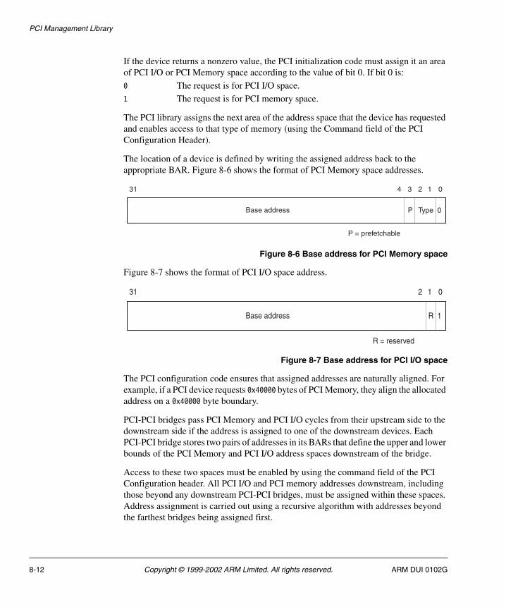
PCI Management Library
If the device returns a nonzero value, the PCI initialization code must assign it an area of PCI I/O or PCI Memory space according to the value of bit 0. If bit 0 is:
0 The request is for PCI I/O space.
1 The request is for PCI memory space.
The PCI library assigns the next area of the address space that the device has requested and enables access to that type of memory (using the Command field of the PCI Configuration Header).
The location of a device is defined by writing the assigned address back to the appropriate BAR. Figure 8-6 shows the format of PCI Memory space addresses.
Figure 8-6 Base address for PCI Memory space
Figure 8-7 shows the format of PCI I/O space address.
Figure 8-7 Base address for PCI I/O space
The PCI configuration code ensures that assigned addresses are naturally aligned. For example, if a PCI device requests 0x40000 bytes of PCI Memory, they align the allocated address on a 0x40000 byte boundary.
PCI-PCI bridges pass PCI Memory and PCI I/O cycles from their upstream side to the downstream side if the address is assigned to one of the downstream devices. Each PCI-PCI bridge stores two pairs of addresses in its BARs that define the upper and lower bounds of the PCI Memory and PCI I/O address spaces downstream of the bridge.
Access to these two spaces must be enabled by using the command field of the PCI Configuration header. All PCI I/O and PCI memory addresses downstream, including those beyond any downstream PCI-PCI bridges, must be assigned within these spaces. Address assignment is carried out using a recursive algorithm with addresses beyond the farthest bridges being assigned first.
Base address
31 234 1 0
0P Type
P = prefetchable
Base address
31 2 1 0
1R
R = reserved
8-12 Copyright © 1999-2002 ARM Limited. All rights reserved. ARM DUI 0102G
PCI Management Library
Assigning interrupt numbers
The PCI specification describes the function of the interrupt line field of the PCI configuration header as operating system dependent, but intended to pass interrupt routing information between the operating system and the device driver. During PCI initialization, the PCI set-up code writes a value into the field. Later, when the device driver initializes the device, it reads the value and passes it to the operating system, requesting an interrupt when the triggering event occurs. When an interrupt is triggered, the operating system must route the interrupt to the correct device driver.
Typically, this value is an offset into the Programmable Interrupt Controller register. For example, the value 5 would mean bit 5 of the register. It is not important what the number is, but the operating system interrupt handling code and the PCI setup code must agree on the meaning.
Each PCI device has four interrupt pins labeled A, B, C, and D. The interrupt pin used by a device is defined in the PCI configuration header for the device in the interrupt pin field. The routing of interrupts between slots and the interrupt controller is entirely system specific. For this reason, the PCI library uses the board-specific function uHALir_PCIMapInterrupt() to find out how interrupts are routed on a particular board.
The interrupt controller might have as few as four PCI interrupts (one per pin) or as many as (number of slots x 4). PCI interrupts might be shared by other devices. In other words, they must allow for their interrupt handler being called with no work to do.
Interrupts from downstream devices are routed through each bridge. Depending on the slot number of the device, the interrupt pin might be transposed as it crosses the bridge. For example, a PCI device interrupting on downstream pin B basic can cause pin C on the upstream side of the bridge to be asserted. The algorithm for working out the upstream interrupt pin that is asserted given a downstream slot number and interrupt pin is:
upstream_pin = (((downstream_pin - 1) + slot) % 4) + 1
where Pin A is 1, B is 2, C is 3, and D is 4. A value of 0, means default (Pin A).
The PCI initialization code applies this algorithm once for each PCI-PCI bridge between the PCI device and the host bridge. When it reaches bus 0, it takes the final pin number and the slot number of the PCI-PCI bridge and calls uHALir_PCIMapInterrupt() to return the interrupt number for the device.
8.3.6 Rebuilding the PCI library
The board-specific subdirectories of the lib directory contains variants of the PCI library in archive format. There are also project files and makefiles in the board-specific subdirectories of AFSv1_4\Source\PCI\Build\.
ARM DUI 0102G Copyright © 1999-2002 ARM Limited. All rights reserved. 8-13
PCI Management Library
8.4 PCI library functions and definitions
The PCI library provides three functions and a number of definitions. These are all contained in AFSv1_4\Source\PCI\Sources\pcilib.h. The PCI library is also used within the boot monitor component. Currently the PCI Library functions on the Intel IQ80310 (XScale-based evaluation board) and on ARM Integrator systems.
The functions are described in
• PCIr_Init
• PCIr_ForEveryDevice
• PCIr_FindDevice
• PCI definitions on page 8-15.
8.4.1 PCIr_Init
This function initializes the PCI subsystem by calling the system-specific uHALir_PciInit() function.
Syntax
void PCIr_Init(void)
8.4.2 PCIr_ForEveryDevice
This function calls the given function once for every PCI device in the system passing the bus, slot, and function numbers for the device. No ordering of devices can be assumed.
Syntax
void PICir_ForEveryDevice (void (action) ( unsigned int, unsigned int, unsigned int))
8.4.3 PCIr_FindDevice
This function finds a particular instance of the PCI device given its vendor and device identifier.
Syntax
int PCIr_FindDevice(unsigned short vendor, unsigned short device, unsigned int instance, unsigned int *bus, unsigned int *slot, unsigned int *func)
8-14 Copyright © 1999-2002 ARM Limited. All rights reserved. ARM DUI 0102G

PCI Management Library
where:
vendor Is the vendor identifier.
instance Is the instance number.
device Is the device identifier.
bus Is the PCI bus to which the device is attached.
slot Is the slot number of the device.
func Is the function of the device.
Return value
0 If it has found the device. The bus, slot, and function number for the device is set up.
nonzero There is not instance occurrences of such a device.
8.4.4 PCI definitions
There are a number of system-specific PCI definitions that are used by the PCI library. These are listed in Table 8-1.
Table 8-1 PCI definitions
Definition Function
UHAL_PCI_IO The local bus address that PCI I/O space has been mapped to.
UHAL_PCI_MEM The local bus address that PCI Memory space has been mapped to.
UHAL_PCI_ALLOC_IO_BASE The address in PCI I/O space that the PCI address allocation must start allocating from.
UHAL_PCI_ALLOC_MEM_BASE The address in PCI Memory space that the PCI address allocation must start allocating from.
UHAL_PCI_MAX_SLOT The maximum number of PCI slots available on PCI bus 0.
ARM DUI 0102G Copyright © 1999-2002 ARM Limited. All rights reserved. 8-15
PCI Management Library
8.5 About µHAL PCI extensions
The ARM Firmware PCI library is independent of the particular system that it is running on. This means that it relies on board-specific code within the µHAL library to initialize the PCI subsystem.
The µHAL PCI extensions provide the following functionality to the PCI library:
Host bridge initialization
This system-dependent initialization is usually performed at system startup and involves setting up the host bridge interface (for example the V360EPC chip on the Integrator system) so that the generic PCI library can access all three areas of PCI memory. This code is held in board.c and driver.s (or b_pci.c and t_pci.s) in the appropriate AFSv1_4\Source\uHAL\Boards\board_name directory. For example, Integrator PCI code is in AFSv1_4\Source\uHAL\Boards\INTEGRATOR.
Access primitives Access primitives allow access to the PCI memory spaces. These are functions and C macros that allow code to access areas of PCI memory without knowing how these areas of memory are mapped to and from local bus memory.
Each PCI supporting target must supply a set of functions that allow access to the three PCI address spaces. Within these functions the target software might need to perform system-specific operations. This system-specific code is external to the PCI library. The set of functions that are supplied as board-specific code (in AFSv1_4\Source\uHAL\Boards\board_name) are described later in this section.
Interrupt routing Each PCI supporting board must supply a function that returns the interrupt number that is associated with the given PCI slot and interrupt pin. This information is used by the PCI library as it assigns resources to individual PCI devices.
PCI resource allocation
The µHAL library for a PCI supporting board exports code and definitions in the µHAL definition file AFSv1_4\Source\uHAL\h\uhal.h.
8-16 Copyright © 1999-2002 ARM Limited. All rights reserved. ARM DUI 0102G

PCI Management Library
8.6 µHAL PCI function descriptions
The standard µHAL library for a particular system includes system-specific PCI extensions to µHAL and system-specific initialization code. This section describes the following µHAL PCI functions:
• uHALir_PCIInit
• uHALr_PCIHost
• uHALr_PCICfgRead8 on page 8-18
• uHALr_PCICfgRead16 on page 8-18
• uHALr_PCICfgRead32 on page 8-19
• uHALr_PCICfgWrite8 on page 8-19
• uHALr_PCICfgWrite16 on page 8-19
• uHALr_PCICfgWrite32 on page 8-20
• uHALr_PCIIORead8 on page 8-20
• uHALr_PCIIORead16 on page 8-21
• uHALr_PCIIORead32 on page 8-21
• uHALr_PCIIOWrite8 on page 8-21
• uHALr_PCIIOWrite16 on page 8-22
• uHALr_PCIIOWrite32 on page 8-22
• uHALir_PCIMapInterrupt on page 8-22.
8.6.1 uHALir_PCIInit
This function initializes the host bridge, for example the V360EPC chip on the Integrator. This board-specific code is not normally called by an application (therefore it has a uHALir prefix). Rather, it is called by the PCI library initialization code PCIr_Init().
Syntax
void uHALir_PCIInit(void)
8.6.2 uHALr_PCIHost
This function tests the board for PCI support.
Syntax
unsigned char uHALr_PCIHost(void)
ARM DUI 0102G Copyright © 1999-2002 ARM Limited. All rights reserved. 8-17
PCI Management Library
Returns
TRUE If the system supports PCI.
FALSE If the system does not support PCI.
8.6.3 uHALr_PCICfgRead8
This function reads 8 bits from PCI Configuration space.
Syntax
unsigned char uHALr_PCICfgRead8(unsigned int bus, unsigned int slot, unsigned int func, unsigned int offset)
where:
bus Is the PCI bus to which the device is attached.
slot Is the slot number of the device.
func Is the function of the device.
offset Is the register offset of the device.
Returns
The 8-bit char from the configuration space.
8.6.4 uHALr_PCICfgRead16
This function reads 16 bits from PCI Configuration space.
Syntax
unsigned short uHALr_PCICfgRead16(unsigned int bus, unsigned int slot, unsigned int func, unsigned int offset)
where:
bus Is the PCI bus to which the device is attached.
slot Is the slot number of the device.
func Is the function of the device.
offset Is the register offset of the device.
Returns
The 16-bit short from the configuration space.
8-18 Copyright © 1999-2002 ARM Limited. All rights reserved. ARM DUI 0102G

PCI Management Library
8.6.5 uHALr_PCICfgRead32
This function reads 32 bits from PCI Configuration space.
Syntax
unsigned int uHALr_PCICfgRead32(unsigned int bus, unsigned int slot, unsigned int func, unsigned int offset)
where:
bus Is the PCI bus to which the device is attached.
slot Is the slot number of the device.
func Is the function of the device.
offset Is the register offset of the device.
Returns
The 32-bit word from the configuration space.
8.6.6 uHALr_PCICfgWrite8
This function writes 8 bits to PCI Configuration space.
Syntax
void uHALr_PCICfgWrite8(unsigned int bus, unsigned int slot, unsigned int func, unsigned int offset, unsigned char data)
where:
bus Is the PCI bus to which the device is attached.
slot Is the slot number of the device.
func Is the function of the device.
offset Is the register offset of the device.
data Is the data written to the device.
8.6.7 uHALr_PCICfgWrite16
This function writes 16 bits to PCI Configuration space.
Syntax
void uHALr_PCICfgWrite16(unsigned int bus, unsigned int slot, unsigned int func, unsigned int offset, unsigned short data)
ARM DUI 0102G Copyright © 1999-2002 ARM Limited. All rights reserved. 8-19

PCI Management Library
where:
bus Is the PCI bus to which the device is attached.
slot Is the slot number of the device.
func Is the function of the device.
offset Is the register offset of the device.
data Is the data written to the device.
8.6.8 uHALr_PCICfgWrite32
This function writes 32 bits to PCI Configuration space.
Syntax
void uHALr_PCICfgWrite(unsigned int bus, unsigned int slot, unsigned int func, unsigned int offset, unsigned int data)
where:
bus Is the PCI bus to which the device is attached.
slot Is the slot number of the device.
func Is the function of the device.
offset Is the register offset of the device.
data Is the data written to the device.
8.6.9 uHALr_PCIIORead8
This function reads 8 bits from PCI I/O space.
Syntax
unsigned char uHALr_PCIIORead8(unsigned int offset)
where:
offset Is the address.
Returns
The 8-bit char from the I/O space.
8-20 Copyright © 1999-2002 ARM Limited. All rights reserved. ARM DUI 0102G
PCI Management Library
8.6.10 uHALr_PCIIORead16
This function writes 16 bits from PCI I/O space.
Syntax
unsigned short uHALr_PCIIORead16(unsigned int offset)
where:
offset Is the address.
Returns
The 16-bit short from the I/O space.
8.6.11 uHALr_PCIIORead32
This function reads 32 bits from PCI I/O space.
Syntax
unsigned int uHALr_PCIIORead32(unsigned int offset)
where:
offset Is the address.
Returns
The 32-bit int from the I/O space.
8.6.12 uHALr_PCIIOWrite8
This function writes 8 bits to PCI I/O space.
Syntax-
void uHALr_PCIIOWrite8(unsigned int offset, unsigned char data)
where:
offset Is the register offset of the device.
data Is the data written to the device.
ARM DUI 0102G Copyright © 1999-2002 ARM Limited. All rights reserved. 8-21
PCI Management Library
8.6.13 uHALr_PCIIOWrite16
This function writes 16 bits to PCI I/O space. The address is given by the offset argument.
Syntax
void uHALr_PCIIOWrite16(unsigned int offset, unsigned short data)
where:
offset Is the register offset of the device.
data Is the data written to the device.
8.6.14 uHALr_PCIIOWrite32
This function writes 32 bits to PCI I/O space. The address is given by the offset argument.
Syntax
void uHALr_PCIIOWrite32(unsigned int offset, unsigned int data)
where:
offset Is the register offset of the device.
data Is the data written to the device.
8.6.15 uHALir_PCIMapInterrupt
This function returns the interrupt number associated with this PCI slot and interrupt pin.
Syntax
unsigned char uHALir_PCIMapInterrupt(unsigned char pin, unsigned char slot)
where:
pin Is the bit position of the interrupt in the programmable interrupt controller for the system.
slot Is the slot number of the device.
Returns
The interrupt number as an 8-bit char.
8-22 Copyright © 1999-2002 ARM Limited. All rights reserved. ARM DUI 0102G

PCI Management Library
8.7 Example PCI device driver
The PCI component of the ARM Firmware Suite contains an example PCI device driver (in AFSv1_4\Source\Pci\Sources\example-driver.c). This demonstrates how a device driver:
• finds the device
• examines its registers
• takes control of its interrupt.
These steps are carried out as follows:
1. Check that the system supports PCI (or is a PCI host):
/* Must be PCI host to initialise the bus */ if (!uHALr_PCIHost ()) { uHALr_printf ("Not PCI host - can't scan the bus \n"); return (OK);}
2. If the system is a PCI host, initialize the PCI subsystem:
/* initialise the bus */ uHALr_printf ("Initialising PCI"); PCIr_Init (); uHALr_printf ("...done \n");
3. Scan the system for the PCI device of interest. In this example, a Digital 21142 ethernet device (with a vendor ID of 0x1011 and a device ID of 0x0019):
/* look for the Digital 21142 ethernet device */if (PCIr_FindDevice(DIGITAL, TULIP21142, 0, &bus, &slot, &func) == 0) { unsigned int ioaddr, memaddr, irq ; int i ;
The instance number in this case is 0 because the code is looking for the first instance. To find the next instance, make another call to PCIr_FindDevice() but with an instance of 1.
4. If the device is found, print out the location of its command and status registers (CSRs) in PCI I/O and PCI Memory. The code is shown in Example 8-2 on page 8-24.
The addresses are from the PCI configuration header for the device. The device is addressed using the PCI bus number, slot number and function number returned by the call to PCIr_FindDevice() in the previous step.
ARM DUI 0102G Copyright © 1999-2002 ARM Limited. All rights reserved. 8-23

PCI Management Library
Example 8-2 Identifying PCI device
/* found it, tell the world */uHALr_printf("Found Digital 21142 ethernet device [%02d:%02d:%02d]\n", bus, slot, func) ;/* work out the location of its CSRs in PCI IO and PCI Memory */ioaddr = uHALr_PCICfgRead32 (bus, slot, func, PCI_MEM_BAR);ioaddr &= ~0x0F ;memaddr = uHALr_PCICfgRead32 (bus, slot, func, PCI_MEM_BAR+ 4);memaddr &= ~0xF ;uHALr_printf("\tCSRs are at 0x%08X (IO) and 0x%08X (Memory)\n",ioaddr, memaddr) ;
5. Make calls to read the device CSRs from PCI I/O space. The CSRs are 64-bit aligned:
/* print out its CSRs (all 15) */for (i = 0; i < 15; i++) {
uHALr_printf("\t\tCSR %02d: %08X\n", i, uHALr_PCIIORead32(ioaddr + (i << 3))) ;
}
6. Find the interrupt number associated with this device from the PCI configuration header.
/* Find its interrupt number and assign it */irq = uHALr_PCICfgRead8 (bus, slot, func,
PCI_INTERRUPT_LINE);uHALr_printf("\tIRQ is @ %d\n", irq) ;
7. Initialize the µHAL interrupt subsystem and request control of the interrupts. At this point, if the device generates an interrupt, tulipInterrupt() is called.
/* init the irq subsystem in uHAL */uHALr_InitInterrupts() ;/* assign the interrupt */uHALr_RequestInterrupt(irq, tulipInterrupt, (unsigned char *)"Digital 21142 interrupt handler") ;
8-24 Copyright © 1999-2002 ARM Limited. All rights reserved. ARM DUI 0102G

PCI Management Library
When the above program is run on a PCI supporting system, the output is similar to that shown in Example 8-3.
Example 8-3 PCI configuration output
ARM Firmware Suite (uHAL v1.4)Copyright ARM Ltd 1999-2002. All rights reserved.Initialising...done Found Digital 21142 ethernet device [00:11:00]CSRs are at 0x00000000 (IO) and 0x40000000 (Memory)CSR 00: FE000000CSR 01: FFFFFFFFCSR 02: FFFFFFFFCSR 03: B96998ADCSR 04: 354F9D62CSR 05: F0000000CSR 06: 32000040CSR 07: F3FE0000CSR 08: E0000000CSR 09: FFF483FFCSR 10: FFFFFFFFCSR 11: FFFE0000CSR 12: 000000C6CSR 13: FFFF0000CSR 14: FFFFFFFFIRQ is @ 15
This shows that the 21142 was found in slot 11 on bus 0. On this system (an Integrator) this means that the device generates interrupts using bit 15 of the interrupt controller. If it is moved to another PCI slot, it might generate a different interrupt.
ARM DUI 0102G Copyright © 1999-2002 ARM Limited. All rights reserved. 8-25

PCI Management Library
8-26 Copyright © 1999-2002 ARM Limited. All rights reserved. ARM DUI 0102G

Chapter 9 Using the DHCP Utility
This chapter describes the Dynamic Host Configuration Protocol (DHCP) utility and how you can use it to load and run applications. It contains the following sections:
• DHCP overview on page 9-2
• Using DHCP on page 9-3
• Configuration files on page 9-4.
ARM DUI 0102G Copyright © 1999-2002 ARM Limited. All rights reserved. 9-1

Using the DHCP Utility
9.1 DHCP overview
Included in the ARM Firmware Suite is a simple standalone application that downloads a binary image over ethernet into memory on the Integrator development board. The main use for this application is downloading large images of several megabytes or more. The application uses the DHCP protocol to obtain the information required to download the image.
DHCP is a super set of the Bootstrap Protocol (BOOTP). DHCP allows a central server to allocate Internet Protocol (IP) addresses to clients on its network.
DHCP is defined by Dynamic Host Configuration Working Group of the Internet Engineering Task Force. The RFC 1541 documentation is downloadable from http://rfc.net/rfc1541.html.
9.1.1 Requirements
You must have a DHCP server for your host machine. Refer to the documentation for your DHCP server for installation and setup details.
You must have a BOOTP client on the target machine. The BOOTP client requires:
• a DHCP server
• the Integrator/AP base platform and core module fitted with SDRAM
• an Intel i8255x based PCI ethernet network card
• Multi-ICE hardware and software.
The code runs standalone only. The standalone image is built to run from 0x8000. It can be programmed into any flash block and the boot switcher will relocate it to 0x8000.
9-2 Copyright © 1999-2002 ARM Limited. All rights reserved. ARM DUI 0102G
Using the DHCP Utility
9.2 Using DHCP
The DHCP application is supplied as a single executable image called dhcp.axf located in the AFSv1_4\Images\Integrator directory. To run use DHCP:
1. Create a configuration file, see Configuration files on page 9-4.
2. Set up your DHCP server to use the configuration file.
3. To get the best performance, set the clock setting to appropriate values for the core module in use. For further details, see Chapter 3 ARM Boot Monitor.
4. Use the ARM Flash Utility (AFU) to program the dhcp.axf image into flash.
5. Reset the development board. The boot switcher runs DHCP application. The application:
a. gets an IP address.
b. gets the details of the file to download from the DHCP server.
c. downloads the file using the TFTP protocol.
d. checks to see if the contents of the file starts with the text string ARMBOOT and, if it does, treats the file as a configuration file.
If the file does not start with ARMBOOT, it is treated as a plain binary file.
6. After an image has loaded, use the following steps to debug using Multi-ICE and AXD:
a. Start the debugger.
b. Load the debug symbols.
c. Set the debugger internal variable $top_of_memory to reflect the size of the SDRAM you have fitted.
d. Enter the start address of the image.
ARM DUI 0102G Copyright © 1999-2002 ARM Limited. All rights reserved. 9-3

Using the DHCP Utility
9.3 Configuration files
A plain-text configuration file provides additional information on how to load an image that is not available from DHCP. Example 9-1 and Example 9-2 show two different configuration files.
Example 9-1 Configuration file for loading an image
ARMBOOTLoad binary-file load-address
Example 9-2 Configuration file for loading and running an image
ARMBOOTRun binary-file load-address execute-address
Where:
binary-file Is the name of the binary image to load.
load-address Is the address in memory to load the image. The default is 0x8000.
execute-address
Is the address in memory where control is passed after the image is loaded. The default is the value used for load-address.
If no configuration file is used, the image is loaded to 0x8000 and run it from this address.
The DHCP application will only load binary images. Use the FromELF utility to generate a binary file from an ELF image.
9-4 Copyright © 1999-2002 ARM Limited. All rights reserved. ARM DUI 0102G
Chapter 10 Chaining Library
This chapter describes the chaining library and how you can use it to chain exception vectors. Its contains the following sections:
• About exception chaining on page 10-2
• The SWI interface on page 10-3
• Chain structure on page 10-8
• Rebuilding the chaining library on page 10-14.
ARM DUI 0102G Copyright © 1999-2002 ARM Limited. All rights reserved. 10-1

Chaining Library
10.1 About exception chaining
Some hardware and software combinations require that an exception vector (especially an interrupt vector) is shared by different code modules. The chaining library provides a mechanism for installing and updating chains of exception vectors. The RESET vector, however, cannot be chained.
For example, the P720T and the VFP hardware require that the IRQ and UNDEF vectors, respectively, must be shared with the debugger. In the P720T case, the serial interrupt can only be directed to an IRQ source, therefore Angel is built to use IRQs for serial interrupts. Hence the µHAL demonstration applications and Angel must share the IRQ vector.
For the ARM10 VFP unit, any exceptions generated by the VFP hardware result in the UNDEF vector being taken. Since RealMonitor uses this vector for breakpoints, it must also be shared between the VFP support code and RealMonitor.
The RealMonitor environment also shares interrupts with the target application. For more information on RealMonitor and chaining, see the RealMonitor Target Controller User Guide.
10-2 Copyright © 1999-2002 ARM Limited. All rights reserved. ARM DUI 0102G
Chaining Library
10.2 The SWI interface
The SWI interface is used to obtain information about the debugger in use and to install the trap handler into the chain for a given vector.
There are two SWIs that are used for interrupt chaining:
SYS_AGENTINFO (0x35)
Initialize a structure detailing debugger information.
SYS_VECTORCHAIN (0x36)
Perform chaining action.
Chaining SWIs are implemented by the boot monitor SWI handler. The Multi-ICE SWI does not support chaining.
10.2.1 0x35, SYS_AGENTINFO
The application uses this SWI to return a pointer to a structure detailing debugger information.
Entry
On entry:
• r0 contains 0x35.
• r1 contains a pointer to two words of memory.
— word 1 is a pointer to a block of memory
— word 2 is the size in words of the memory structure.
Note If the size of the memory structure in word 2 is less than 20 words, the
returned values are limited to those that fit into the first size words of the _Debugger_info structure and later values are not accessible.
ARM DUI 0102G Copyright © 1999-2002 ARM Limited. All rights reserved. 10-3

Chaining Library
Return
For the Debugger Info SWI, if the call was successful on exit r0 contains a pointer to a _Debugger_info structure:
struct _Debugger_info{ char Agent_ID[32]; char Agent_Copyright[32]; unsigned int id_version; unsigned int semihosting_version; unsigned int owned_defined_vectors;};
Where:
Agent_ID
Is a zero-terminated string showing the ID code for the debugger in use. For example, "Angel Debug Monitor v1.32" is returned for the Angel debugger.
Agent_Copyright
Is a zero-terminated string showing the semihosted version number, for example, "ARM Limited 1996-2000".
id_version Agent id and version number. The version number being the lower half word encoded as 100 times the dotted number, for example 1.41 => 141. The Agent id is the upper half word and is encoded as:
Multi-ICE 0x1001
Angel 0x2001
µHAL 0x2002.
semihosting_version
The version of the semihosting spec the agent supports, 100 times the dotted number, for example A-06 is "1006".
owned_defined_vectors
Bit field denoting the vectors used and/or initialized by the owner. The upper half word denotes vectors used by the owner and the lower half word denotes the vectors initialized by the owner but not necessarily used. If a bit is 0, the vector is unused.
10-4 Copyright © 1999-2002 ARM Limited. All rights reserved. ARM DUI 0102G

Chaining Library
The vectors for each bit position are:
Bit 0 Reset Vector
Bit 1 UNDEFINED Vector
Bit 2 SWI Vector
Bit 3 Prefetch Abort Vector
Bit 4 Data Abort Vector
Bit 5 Reserved Vector
Bit 6 IRQ Vector
Bit 7 FIQ vector.
For example, 0x00FE00FE denotes that Angel provides chaining support for each of the vectors except the reset vector and uses all but the reset vector.
If the call was not successful, on exit r0 contains -1.
10.2.2 0x36, SYS_VECTORCHAIN
This SWI is used by the application to perform the required chaining task.
Entry
On entry:
• r0 contains 0x36.
• r1 contains a pointer to three words of memory.
— Word one contains the vector number to chain on. 0 is Reset, 1 is Undef, and so on.
— Word two is the chaining task to perform:
0x0 Add element to the chain (see Adding a vector element on page 10-6).
0x1 Remove element from the chain (see Removing a vector element on page 10-6).
0x2 Update the chain (see Updating a vector element on page 10-7).
0x3 Initialize the chain (see Initializing the chain on page 10-7).
— Word three contains a pointer to the chain structure (see Chain structure on page 10-8).
ARM DUI 0102G Copyright © 1999-2002 ARM Limited. All rights reserved. 10-5

Chaining Library
Return
Register r0 contains:
0 The task was successfully performed, but no elements were removed.
pointer If the call was successful and resulted in the removal of a chain element, a pointer to the removed element is returned.
-1 The call was not successful.
Adding a vector element
To install an element into the chain, the application must:
1. Set up a suitable chain structure.
2. Call SWI 0x36 with chaining task 0x0 to process the request.
There are three possible successful results from the attempt to add an element:
• If the element is already present in the chain, the new element replaces the original element and a pointer to the original element structure is returned. (The presence of the element is determined by comparing the exec_routine address and the destination location of element.)
• If the priority of the new element is less than or equal to an existing element, the new element is inserted into the chain ahead of the original element.
• If the end of the chain is reached, the element is added at the end of the chain.
A return value of either 0x0 or the address of the replaced element denotes success.
Removing a vector element
To remove an element from the chain, the application must:
1. Set up a suitable chain structure with the vector and exec_routine elements describing the element to remove. If the structure pointer parameter is Null the entire chain for that vector is removed.
2. Call SWI 0x36 with chaining task 0x1 to process the request.
A return value of 0x0 denotes success. The element was removed and the chain links adjusted.
A value of -1 denotes failure. The element could not be removed from the chain.
10-6 Copyright © 1999-2002 ARM Limited. All rights reserved. ARM DUI 0102G

Chaining Library
Note Only user elements may be removed from the chain using the remove element task. Owner elements can only be removed by an initialize chain task.
Updating a vector element
The update task is used to change handler priority within the chain. To update an element in the chain, the application must:
1. Set up a suitable chain structure. The exec_routine must match an element already in the chain.
2. Call SWI 0x36 with chaining task 0x2 to update the chain.
The chain owner walks the chain for the given vector, if the exec_routine of a chain element and the given chain structure match that element is removed and the new chain element added to the chain automatically using the ADD_ELEMENT task.
A return value of -1 denotes failure and the element was not updated within the chain.
If successful, the return value points to the chain element that was removed from the chain and replaced with the new element.
Initializing the chain
The initialize chain task is used to remove all links from the chain. To initialize the chain the application must:
1. Setup a suitable chain structure with the vector_id element correctly set.
2. Use SWI 0x36 with a chaining task of 0x3.
A return value of 0x0 denotes success. The chain for the given vector is set to Null and will not be used until a new element is added.
Note If the pointer to the chain element structure passed using SWI 0x22 is Null then nothing is done and the return value from the SWI is 0x0 denoting success.
ARM DUI 0102G Copyright © 1999-2002 ARM Limited. All rights reserved. 10-7
Chaining Library
10.3 Chain structure
The chain is a linked list. Each element of the chain has the following structure:
struct _ChainLink{ unsigned int owner; void (* test_routine)(void *); unsigned int priority; void (* exec_routine)(void); struct _ChainLink * next_element;};
Where:
owner Identifies owner of the vector:
0 This is a user element added by an application.
1 This element was added by a vector owner.
test_routine
Pointer to the exception test routine. Control is passed to this routine with r0 to r5, r12 and lr stacked, r0 contains a pointer to the stacked lr. On return, r0 contains:
-1 The exception caused an error in the test routine.
0 The exception is for this chain and has been handled, the lr must have been updated for return to the application.
1 The exception is for this chain element.
2 The exception is not for this chain element.
priority The required handler priority in the chain. The highest priority is zero and increasing values indicate lower priority. There is not an upper limit to the value of priority since there is not a limit to the number of elements in the chain.
exec_routine
Pointer to the handler routine. Control is passed to this routine as if it had been inserted into the vector table.
next_element
Pointer to the next element in the chain.
10-8 Copyright © 1999-2002 ARM Limited. All rights reserved. ARM DUI 0102G

Chaining Library
10.4 Owners and users
The vector owner provides the SWI interface that maintains the vector chain. The application uses the SWI interface to determine if the required vector is in use by the debugger.
10.4.1 Element owners
The owner of the vectors, whether that is µHAL, RealMonitor, or Angel, provides the interface described in The SWI interface on page 10-3 to return a pointer to the DebuggerInfo structure and to support adding, removing, and updating of the vector chain for each of the vectors.
Angel initialization
Angel boots from ROM and claims all of the vectors for itself. It calls angel_BootInit to initialize the Debugger Info structure described in 0x35, SYS_AGENTINFO on page 10-3 with:
Agent_ID "Angel Debug Monitor v1.32"Agent_Copyright "ARM Limited 1998-2000"id_version "2001"semihosting_version "1006"owned_defined_vectors 0x00FE00FE
At this point all of the vector chains are Null.
ARM DUI 0102G Copyright © 1999-2002 ARM Limited. All rights reserved. 10-9
Chaining Library
Angel and chaining
Angel provides the owner side of the chaining mechanism since it is switched to at boot and by default claims all of the vectors for itself, irrespective of whether or not it uses them. However due to the complex nature of the Angel IRQ and FIQ interrupt handlers there are two restrictions that are specific to Angel:
• The application being debugged might be an OS that is performing interrupt driven context switches (for example the ping demo within µ/COS–II).
Because Angel re-enables interrupts while servicing the interrupt, two applications would potentially be storing and swapping context in the same processor mode at the same time.
This restriction is dealt with by masking the application interrupts when Angel has stopped the application so that the chaining trap handler is executed on Angel interrupts only. Angel simply stores the state of the interrupt controller mask and masks all but the Angel interrupts when the application task is stopped. When Angel then restarts the application task the original interrupt mask is returned.
• Angel has no way of knowing if the application has been reloaded, a new application has been loaded or simply that some data has been modified at a particular memory address. Angel views these as writes to memory and has no way of distinguishing between them.
The second of the restrictions is dealt with by clearing the application interrupt mask so that the application interrupts are not restarted until the application does so. The chains for each of the vectors are removed so that the vector chains are not used until the application re-initializes them. There are two situations that use this process:
— the application is terminated, using angel_SWIreason_ReportException (0x18) SWI with the reason code ADP_Stopped_ApplicationExit
— an application is loaded (or reloaded) resulting in a call to angelOS_InitialiseApplication.
Chaining is provided within Angel only if it is built with the build option CHAIN_VECTORS=1 set within devconf.h for the given board.
10-10 Copyright © 1999-2002 ARM Limited. All rights reserved. ARM DUI 0102G

Chaining Library
µHAL initialization
Angel boots from ROM and claims all of the vectors for itself. It calls angel_BootInit to initialize the Debugger Info structure described in 0x35, SYS_AGENTINFO on page 10-3 with:
Agent_ID "uHAL v1.4"Agent_Copyright "ARM Limited 1998-2002"id_version "2002"semihosting_version "1006"owned_defined_vectors 0x00FE00FE
At this point all of the vector chains are Null. If Chainir_Init() is called by a semihosted image that does not own the vectors, the standalone image has already initialized any owner chained elements so only user chain elements are removed.
ARM DUI 0102G Copyright © 1999-2002 ARM Limited. All rights reserved. 10-11
Chaining Library
µHAL and chaining
Because µHAL can be both the owner of the vectors and the application wishing to use them, it must provide both sides of the chaining mechanism.
The owner side of the mechanism is supported by the boot monitor and boot switcher, since this is run at boot and is the owner of the vectors. A standalone image wishing to use the chaining mechanism, but not wishing to install its own SWI handler, can use the SWI interface. The SWI can return information about the system and add or remove elements from any vector chains as required.
However, any semihosted or standalone images might also be µHAL based. Therefore, the application side of the chaining mechanism is also provided by µHAL. When a request is made to µHAL to install IRQ and FIQ handlers, µHAL first determines if the vectors are already in use by the image that was run at boot. If the vectors are in use, the library code performs any suitable chaining requests as required.
The chaining code is provided as a library. To build an application to use the chaining library the µHAL library must use the build option CHAIN_VECTORS=1. The µHAL library then makes nonweak links to chaining routines requiring the chaining library AFS component to be explicitly added to the application link stage
Handling exceptions
On an exception being taken, the exception vector causes a branch or a load pc to the vector owners trap handler. If there is a chain installed for the exception vector, the first test routine is called to determine if it is owner of the exception.
If the test routine returns success, control is passed to the exec routine as if it had been called directly from the exception vector.
If the test routine returns failure, the next element in the chain is tested. The tests are repeated until either one of the chain elements claims the exception or the last element in the chain is reached. If none of the chained handlers claims the exception, or no chains are installed, the exception is passed onto the debuggers trap handler to process.
The test routine might also return HANDLED, in this case the exception was dealt with, lr updated, and control passed back to the application.
If an error occurred during the handler evaluation, the test routine returns an error.
10-12 Copyright © 1999-2002 ARM Limited. All rights reserved. ARM DUI 0102G

Chaining Library
10.4.2 Element users
The application must use the SWI mechanism to determine if the given vector it requires is in use by the debugger. The installation of the exception handler must be done appropriately depending on whether there are other users of the vector.
Refer to the µHAL bubble demo in AFSv1_4\Demos for an example of interrupt initialization:
1. The application attempts to initialize interrupts and install its trap handler using uHALir_InitInterrupts().
2. uHALir_ResetInterrupts() sets up uHALiv_IRQMode to the correct state. In this case, uHALiv_IRQMode is set to IRQMODE_CHAINED since the return value from the Chainir_DebuggerFlags() routine shows that all vectors are claimed by the debugger.
3. The trap handler is installed by uHALir_NewIRQ(). This uses uHALiv_IRQMode to determine whether or not to chain the handler.
4. In this example, Chainir_Chain_Vectors() adds the trap handler to the IRQ chain.
Each of the vector chains are installed in the same manner.
ARM DUI 0102G Copyright © 1999-2002 ARM Limited. All rights reserved. 10-13
Chaining Library
10.5 Rebuilding the chaining library
Use the project files or makefiles to rebuild the chaining library.
10.5.1 PC project files
You can build the library with ADS 1.0 (or higher) CodeWarrior IDE project files (Chain_lib.mcp).
10.5.2 Unix makefile
The CD has a makefile for use on a Unix workstation. (You can also use the makefile on a PC.)
There is a makefile for rebuilding the library for a single development board and processor combination. For example, to rebuild the library for the Integrator board with an ARM940T processor, use AFSv1_4/Source/ChainLibrary/Build/Integrator940T.b/makefile.
If you have an Integrator board with an ARM7TDMI core, use the generic Integrator files located in AFSv1_4/Source/ChainLibrary/Build/Integrator.b/makefile.
You must maintain the hierarchy of the CD directories when you copy the files from the CD to your workstation. The makefile defines ROOT as the root of the build tree. TOOLS is the tools directory that contains build tools of various kinds.
10-14 Copyright © 1999-2002 ARM Limited. All rights reserved. ARM DUI 0102G

Chapter 11 Libraries and Support Code
This chapter describes some of the internal operation of the libraries and how they support applications and hardware. It contains the following sections:
• Library naming on page 11-2
• Rebuilding libraries on page 11-3
• Support for VFP on page 11-5
• Support for the ADS C library on page 11-13.
ARM DUI 0102G Copyright © 1999-2002 ARM Limited. All rights reserved. 11-1
Libraries and Support Code
11.1 Library naming
The prebuilt AFS libraries use the following scheme to identify build characteristics:
<Component>_<Stack><Run_mode><Endian>.a
Where:
Component The library component, for example:
uHAL The basic µHAL library.
PCI The library for PCI bus support.
Flash The library for Flash memory functions.
Chain The library for interrupt vector chaining.
Stack Indicates if software stack checking is used:
u No stack checking.
s Uses stack checking.
Run-mode Indicates how the image is run:
r ROM image, lives in flash or ROM.
_ Semihosted image, load and run through a debugger.
Endian Specifies how the software treats the byte order in words:
l Little-endian.
b Big-endian.
.a Indicates that the file is a library archive.
For example, uHAL_url.a is the µHAL library built little endian with no stack checking and will be run from flash.
The name of the subdirectory within the lib directory identifies the board and processor. If a library is in the directory AFSv1_4\lib\Integrator720T then it has been built for an Integrator system with an ARM 720T header fitted. If you have an ARM 7TDMI core, use the generic code in AFSv1_4\lib\Integrator.
11-2 Copyright © 1999-2002 ARM Limited. All rights reserved. ARM DUI 0102G

Libraries and Support Code
11.2 Rebuilding libraries
There are three ways of building the AFS components:
• using ARM .mcp project files for the CodeWarrior IDE with ADS 1.0 or higher
• using GNU makefiles (Windows and Cygwin make or Unix gnumake).
The library components in the Source directory contain source code and build control files for the library. There are build files for each development board and processor combination. For example, to rebuild the µHAL library for an Integrator board with a ARM 940T processor, use the build files in: AFSv1_4\Source\uHAL\Build\Integrator940T.b\. To rebuild the library for an Integrator board with an ARM 7TDMI core, use the generic code in AFSv1_4\Source\uHAL\Build\Integrator.b\.
Note Some libraries are supplied prebuilt and without source code. For example, the flash library has files for Integrator and Prospector boards in both semihosted and standalone versions. The .a extension for these files indicates that they are in armar format.
11.2.1 Using the CodeWarrior IDE
The CodeWarrior IDE project files (.mcp extension) are the build files designed for use with ADS. Operation instructions and help are available from the ADS manuals or through the on-line help available within the CodeWarrior IDE.
The build system is initiated by either:
• using the Host PC point and click interface to select the .mcp file
• selecting the CodeWarrior icon and loading the required project file using Project → Open from the CodeWarrior IDE Menu.
Either of these methods starts the IDE and makes the required project the focus window.
11.2.2 Using makefiles
To build µHAL and its associated components using makefiles use GNUmake. GNUmake is available for UNIX, and for Windows 95 and Windows NT.
Note Before you can use GNUmake with Windows 95, Windows 98, or Windows NT, you must first install CygWin. For more information about the Cygwin project, it is recommended that you contact Redhat at: http://sources.redhat.com
ARM DUI 0102G Copyright © 1999-2002 ARM Limited. All rights reserved. 11-3

Libraries and Support Code
11.2.3 Output formats
The CodeWarrior IDE, and GNUmake build ELF files for standalone and semihosted operation. Some of the build tools also make other formats. The formats supported by AFS are:
output.axf This is an ARM eXecutable Format (.axf) file that is an ELF format image. This can be converted into other formats by using the fromELF utility.
output.a This is an ARM library (armar) format image used with ADS. (This format is used when a library is created that will be linked with other code.)
output.bin This is a plain binary image.
Use the fromELF utility to produce other formats, for example Motorola S-record. For more information on image formats, see the documentation for your ARM toolkit.
11-4 Copyright © 1999-2002 ARM Limited. All rights reserved. ARM DUI 0102G

Libraries and Support Code
11.3 Support for VFP
This section describes how µHAL supports the ARM10 VFP unit.
Note Support for the ARM10 VFP unit is not available in all tool-chain versions.
11.3.1 Introduction
The Vector Floating-Point (VFP) unit is provided as a coprocessor extension to the ARM10 core, providing both single and double precision floating-point arithmetic. It supports five floating-point exceptions:
• Invalid Operation
• Division by Zero
• Overflow
• Underflow
• Inexact.
The support code that extends the µHAL library handles infrequently occurring values and exceptions. This increases the execution speed of frequently encountered operations. Therefore all operations on infinities, Not a Number (NaNs) and denormals, as well as all floating-point operations, are handled by support code.
The support code:
• performs the function of compliant hardware
• is transparent to the user
• returns the required result to the destination register and might call the user trap handler.
The support code has three distinct sections:
• an initialization routine that performs all system initialization required to use the VFP unit
• an exception handler that determines if the VFP unit initiated the exception and handles the exception if appropriate
• a library of routines that perform the required computations, such as divide with unsupported types (NaN, denormals and infinities).
ARM DUI 0102G Copyright © 1999-2002 ARM Limited. All rights reserved. 11-5

Libraries and Support Code
11.3.2 Implementation in µHAL
The libraries supplied with ADS 1.1 and later provide software implementation of the required floating-point operations as well as VFP implementations. The VFP unit signals an exception through the Undefined Exception Vector. It is the task of the support code to determine if the exception originated from the VFP unit and perform the required corrective action.
Initialization
By default the VFP unit is disabled, to enable it:
1. Clear the VFPTST[13:12] bits by writing to the hardware register CM_INIT.
2. Set EN[30] within the Exception Status Word FPEXC.
3. Calling VFPir_Init() installs the Undefined Exception Handler in the standalone case.
All VFP initialization must be carried out prior to calling _fp_init(), since this clears the hardware floating-point status register (FPSCR). Any access to the VFP unit before it is initialized causes an Undefined Exception.
Exception handler
When an undefined exception is taken, VFPir_TestException is called to determine if the VFP unit initiated the exception. The test uses either:
• the chaining mechanism
• the VFPir_execRoutine installed directly into the vector.
The sequence for exception handling is:
1. Status FPEXC[31] is examined to determine whether the VFP unit initiated the exception. If clear, the instruction causing the exception is examined to determine if the user application generated an undefined exception and is attempting to install a default handler (see User trap handlers on page 11-11).
11-6 Copyright © 1999-2002 ARM Limited. All rights reserved. ARM DUI 0102G

Libraries and Support Code
2. If the VFP unit did initiate the exception, control is passed onto the exception handling routine VFPir_ExceptionHandler.
• On entry, the hardware floating point status word is copied into the software floating point status word to ensure that all floating point operations are carried out with the same starting status.
• On exit, the status after performing the exceptional operation, including any cumulative exception flags, is saved back to the hardware. The support code is therefore transparent to the user.
3. Having identified the exceptional instruction from FPINST it is executed using the software floating point library. This:
• carries out the appropriate handling of unsupported data types
• sets the condition and cumulative exception flags appropriately within the software floating point status word.
4. If the exception is enabled within the FPSCR, the support code:
• attempts to perform the exceptional operation itself
• passes control onto the users trap handler associated with that exception.
It must perform the instruction itself in order to ensure that it was exceptional and to obtain the required VFP status.
5. Upon returning from the VFP exception, handler control is passed back to the main application. The return value indicates how the exception was handled.
0 The exception has been handled and the correct status is restored.
-1 The exception has not been handled or the exception was not initiated by the VFP unit. If present, the original undefined exception handling code is resumed, otherwise control is passed back to the application.
1 Control is passed to the users trap handler using the mechanism described in User trap handlers on page 11-11.
11.3.3 Library support for VFP
The ADS floating-point libraries are provided in a number of formats.
Each of the libraries provide the same overall functionality, in that all the routines provided perform the same operation. However, the instruction sets used differ from library to library. The linker selects the library variant best suited to the accumulated ATPCS options.
The support code is linked against the IEEE floating-point libraries and provides full IEEE rounding and exception options. (The IEEE floating-point libraries are prefixed with the letter g.)
ARM DUI 0102G Copyright © 1999-2002 ARM Limited. All rights reserved. 11-7

Libraries and Support Code
By using the software floating-point library to perform all exceptional operations within the support code instead of using the VFP unit in intermediate operations, the VFP status does not have to be saved.
VFP routines
Table 11-1 lists the routines that are provided for the user application.
Table 11-1 VFP routines
Function template Description
void VFPir_Init (void); Installs the VFP exception handler, either into a chain of handlers for the UNDEF exception or into the vector itself. Also enables the VFP unit by clearing the VFPTST bits in CM_INIT and enabling the device in FP_EXC.
void VFPir_Disable (void); Removes the VFP exception handler from the chain of handlers for the UNDEF exception. Also disables the VFP unit by setting the VFPTST bits in CM_INIT and clearing the FP_EXC register.
void VFPir_ExecRoutine (void); If chaining is not supported, determines if the exception is a VFP exception passing control onto the exception handling code, otherwise control is passed directly to the handling code. Checks the return value for handled, not handled or pass onto user handler.
unsigned int VFPir_ReadFPSCR(void); Reads the FPSCR VFP register.
unsigned int VFPir_ReadFPINST(void); Reads the FPINST VFP register.
unsigned int VFPir_ReadFPEXC(void); Reads the FPEXC VFP register.
void VFPir_WriteFPSCR(unsigned int); Writes the FPSCR register.
void VFPir_WriteFPEXC(unsigned int); Writes the FPEXC register.
unsigned int VFPir_ReadFPSID(void); Reads the FPSID register.
int VFPir_SaveContext
(VFP_Context *ptrVFPContext);
Saves the context of the VFP hardware, saving each of the VFP registers.
void VFPir_RestoreContext
(VFP_Context *ptrVFPContext);
Restores the context of the VFP hardware, restoring each of the VFP registers.
11-8 Copyright © 1999-2002 ARM Limited. All rights reserved. ARM DUI 0102G
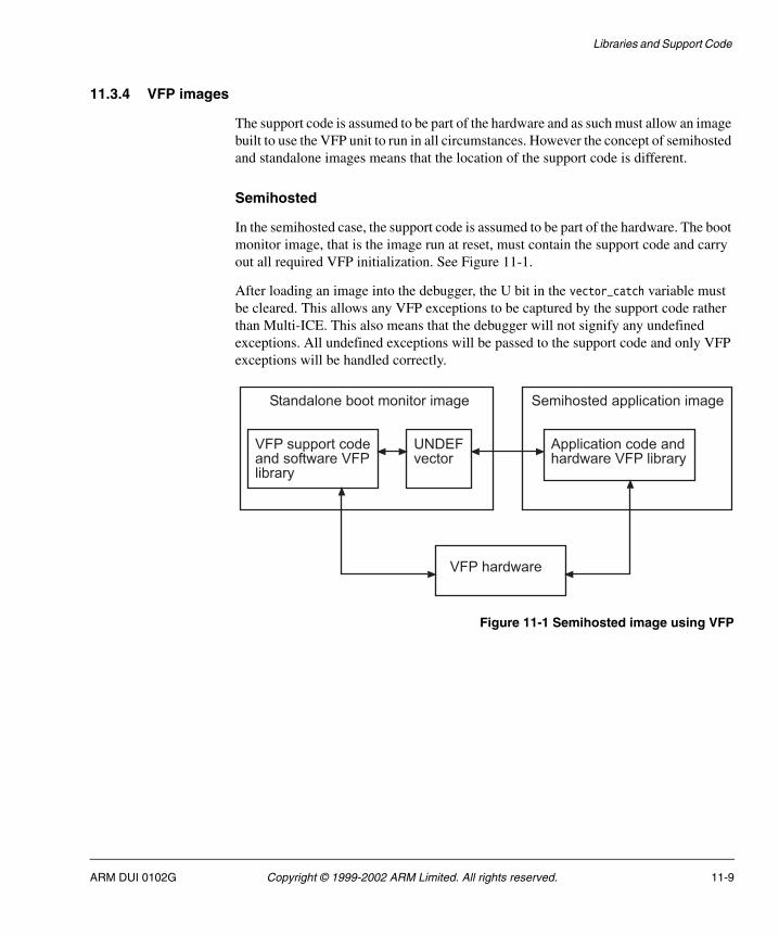
Libraries and Support Code
11.3.4 VFP images
The support code is assumed to be part of the hardware and as such must allow an image built to use the VFP unit to run in all circumstances. However the concept of semihosted and standalone images means that the location of the support code is different.
Semihosted
In the semihosted case, the support code is assumed to be part of the hardware. The boot monitor image, that is the image run at reset, must contain the support code and carry out all required VFP initialization. See Figure 11-1.
After loading an image into the debugger, the U bit in the vector_catch variable must be cleared. This allows any VFP exceptions to be captured by the support code rather than Multi-ICE. This also means that the debugger will not signify any undefined exceptions. All undefined exceptions will be passed to the support code and only VFP exceptions will be handled correctly.
Figure 11-1 Semihosted image using VFP
?7���#�����������������������?7� �)����
�� �������������������������?7�� �)����
������ ����)���������������!� �������������� �����������!�
?7����������
-*�'7������
ARM DUI 0102G Copyright © 1999-2002 ARM Limited. All rights reserved. 11-9

Libraries and Support Code
Standalone
In the standalone case, the image is executed from reset. The support code must, therefore, be included as part of the image. This creates problems with linking the image due to name space pollution caused by two versions of each VFP routine (one with support for hardware and one with software support). See Figure 11-2.
Figure 11-2 Standalone image with VFP code
The VFP support code is built with the compiler and assembler option -fpu softVFP. The remaining image code sections are built to use the compiler and assembler option -fpu VFP, including the µHAL library. If at the link stage, the application contains a call to fdiv(), this uses the VFP hardware. The support code also contains the call to fdiv() to be able to handle exceptional division operations, however, this is implemented in software. So in the same image many routines exist which require two different implementations.
To overcome these problems, the support code is generated as a partially linked object with all software floating point library symbols hidden. This object is then linked into the standalone application, built to use hardware VFP, and provides the appropriate VFP support code hooks, such as VFPir_Init(). Thus all of the floating point functionality used within the application uses the VFP hardware and within the support code the software floating point library implementations.
By using this mechanism to provide the required software floating point implementation of the VFP support code, standalone µHAL applications always link against the latest version of the floating point library.
The VFP support code is only included in the Integrator boot monitor, and in any Integrator1020T µHALDemos, if they are built with FP_SUPPORT=1 with ADS 1.1 or later tools.
?7���#�����������������������?7� �)����
�� �������������������������?7�� �)����
������ ������� �����������!�
?7����������
-*�'7������
11-10 Copyright © 1999-2002 ARM Limited. All rights reserved. ARM DUI 0102G
Libraries and Support Code
11.3.5 User trap handlers
You can install your own exception handlers so that a given exception is handled in a user defined manner. This is done using the default exception handler provided by the ADS C libraries. The default handler passes control onto the user’s exception handlers.
The first step is to present the default exception handler to the support code using the Undefined exception handler. The address of the library exception handler is stored in r1 and the exception code 0x1 in r0. The undefined instruction 0x56465031 (ASCII "VFP1") is then executed.
The code segment in Example 11-1 installs the routine LibraryTrapHandler as the default exception handler for enabled exceptions.
Example 11-1 Installing exception handler
; First define the required VFP instruction using the DCI assembler directive MACRO UNDEF_VFP_INST DCI 0x56465031 ; VFP1 MEND
; Now use the defined macro as needed, setting up the required registers. LDR r1, =LibraryTrapHandler MOV r0, #1undefined_label UNDEF_VFP_INST
This causes an undefined exception that is identified by the support code as the user attempting to install its own exception handler. This requires that the support code undefined exception handler has already been setup to capture the VFP exception, so all VFP initialization must already have taken place.
Thus on an enabled exception now occurring the support code attempts to deal with the exception in the usual manner. Once it has established the exception type and that it is enabled, the required VFP status is saved and control passed onto LibraryTrapHandler in the above case, in the processor mode prior to the exception.
ARM DUI 0102G Copyright © 1999-2002 ARM Limited. All rights reserved. 11-11
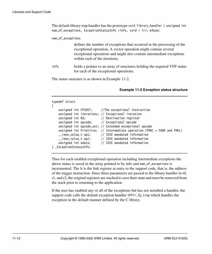
Libraries and Support Code
The default library trap handler has the prototype void library_handler ( unsigned int num_of_exceptions, ExceptionStatusInfo *info, void * lr); where:
num_of_exceptions
defines the number of exceptions that occurred in the processing of the exceptional operation. A vector operation might contain several exceptional operations and might also contain intermediate exceptions within each of the iterations.
info holds a pointer to an array of structures holding the required VFP status for each of the exceptional operations.
The status structure is as shown in Example 11-2.
Example 11-2 Exception status structure
typedef struct{ unsigned int FPINST; //The exceptional instruction unsigned int iterations; // Exceptional iteration unsigned int Rd; // Destination register unsigned int opcode; // Exceptional opcode unsigned int opcode_ext; // Extended exceptional opcode unsigned int Primitive; // Intermediate operation (FMAC = FADD and FMUL) __ieee_value_t op1; // IEEE mandated information __ieee_value_t op2; // IEEE mandated information unsigned int edata; // IEEE mandated information} _ExceptionStatusInfo;
Thus for each enabled exceptional operation including intermediate exceptions the above status is saved in the array pointed to by info and num_of_exceptions is incremented. The lr is the link register at entry to the support code, that is, the address of the trigger instruction. Since three parameters are passed to the library handler in r0, r1, and r2, the original registers are stacked to save their state and must be removed from the stack prior to returning to the application.
If the user has enabled any or all of the exceptions but has not installed a handler, the support code calls the default exception handler VFPir_fp_trap which handles the exception in the default manner defined by the C library.
11-12 Copyright © 1999-2002 ARM Limited. All rights reserved. ARM DUI 0102G
Libraries and Support Code
11.4 Support for the ADS C library
This section describes the effect of linking µHAL applications with the C library, the differences between the build variants and how µHAL functions that are duplicated within the C library are redirected to use C library implementations.
11.4.1 Introduction
All µHAL applications, by default, link against the C library. The linker therefore, always scans the appropriate C library for any non-weak references not resolved by µHAL library. Any µHAL application referencing C library functionality (such as malloc()) causes the linker to include the library member, as well as all associated library members, routines, and initialization code.
If required, initialization of the library routine is performed within µHAL startup code. For example in the above case _init_alloc() is called within uHALir_ClibInit() to initialize the library heap allocator.
If a routine, for example malloc(), is not used either directly by the application or by any indirect calls such as getchar(), the library heap initialization is not included in the image and is therefore not performed within µHAL startup.
ARM DUI 0102G Copyright © 1999-2002 ARM Limited. All rights reserved. 11-13

Libraries and Support Code
Library members, routines, and definitions are included in the image if and only if they are referenced by the application, directly or indirectly, including library initialization routines.
Note There is a single exception to the standard initialization sequence. Floating-point initialization is performed on the condition that the µHAL library has been built to use only software floating point emulation. If hardware support were present in the target, that would negate the requirement for the C library floating-point initialization code.
11.4.2 Build variants
Any µHAL application can be built to link against the C library in one of two ways:
• Use the helper functions provided by µHAL, such as __rt_udiv() and __raise().
• Use the helper functions provided by the C library. This selection is controlled by the build option USE_C_LIBRARY.
If you use build option USE_C_LIBRARY=0, the µHAL helper functions are included. These functions provide only minimal functionality from the C library. A single library member is included:
• rt_memcpy_w.o (defines _memcpy_lastbytes and __rt_memcpy_w).
If you use build option USE_C_LIBRARY=1, any library members referenced by the µHAL application and the following C library helper functions are included:
• _get_argv.o
• rt_memcpy_w.o
• callvia.o
• rt_raise.o
• rt_udiv.o
• sys_command.o
• __raise.o
• rt_div.o
• use_semi.o
• defsig.o
• sigdefs.o
• rt_memcpy.o
• sys_wrch.o.
11-14 Copyright © 1999-2002 ARM Limited. All rights reserved. ARM DUI 0102G

Libraries and Support Code
In order to build µHAL applications that do not use the C library, the memcopy() routine __rt_memcpy_w() must be provided (__16__rt_memcpy_w() must also be provided if built to use interworking). However, if the application references any C library routine, all associated library members are included in the output image, irrespective of USE_C_LIBRARY. This can be prevented only by the use of the -noscanlib link option. This option causes a link failure if non µHAL library functions are referenced.
11.4.3 Retargetting
If the µHAL application references C library functionality that is implemented within µHAL, the µHAL duplication is retargetted and calls are redirected to the C library implementation.
For example, in an application using the C library routine printf(), any subsequent calls to uHALr_printf() are redirected to the C library implementation, printf(). This is repeated for malloc(), free(), getchar(), putchar() and getc().
However, if the application links against the C library but makes no reference to non µHAL functionality, none of the µHAL functions (for example, uHALr_printf() and uHALr_malloc()) are retargetted and appropriate C library initialization is not performed.
Initialization
The C library provides all necessary startup and initialization code required to generate a semihosted image. However, standalone program startup and initialization is not supported by the C library, due to its target specific nature. For µHAL to remain in control of the system, in both the standalone and semihosted cases, library initialization is performed by µHAL during startup. The library initialization routines are:
• __rt_stackheap_init()
• _init_alloc()
• _initio().
On branching to main, both the heap and stacks and the standard input output streams have been initialized.
The floating-point initialization must also be performed. (The VFP support code performs the initialization if an image is built to use floating-point.)
ARM DUI 0102G Copyright © 1999-2002 ARM Limited. All rights reserved. 11-15
Libraries and Support Code
Memory model
The locations of the stack and heap and their respective sizes are defined using the interface provided by the library. Two memory models are supported by the default implementation from the library:
• Single memory region allocated to both the stack and the heap.
• Two memory regions with one allocated to the stack and the other to the heap.
In the third customized option, a new memory model is defined using the library interface provided. This is the option used by µHAL, since it is the most flexible and µHAL retains control of memory management. The following functions are used to customize the memory model.
__rt_stack_heap_init()
Is provided to define a new memory model.
__rt_stack_overflow()
Is also provided if the images are to be built with stack checking.
As µHAL initializes stacks separately, __rt_stack_heap_init() returns only the lower and upper bounds of heap in registers r0and r1. _init_alloc() then uses this data to initialize library heap management.
The stack pointers for the various processor modes are initialized during µHAL startup and because the C library inherits these stacks, no further stack initialization is required. By providing a valid heap and stack, as shown above, the library memory management facilities, malloc(), realloc(), calloc() and free() are used unchanged from the library.
If the heap is fully allocated, __rt_heap_extend() is called. It attempts to return a pointer to the location of the extended heap, this interface can be used to provide additional noncontiguous blocks of memory to extend the heap. The library does not define a default implementation of this, however, it is used by the memory manager if defined. The current implementation simply returns zero in r0, denoting failure.
11-16 Copyright © 1999-2002 ARM Limited. All rights reserved. ARM DUI 0102G

Libraries and Support Code
I/O
Each of the I/O functions is based on a SWI interface. Since there is no support within µHAL for the SWI interface in the standalone case, some tailoring of the library is necessary to present a common interface between the standalone and semihosted images for the printf and scanf families. For the standalone case there is no file system and file I/O requests are denied in a suitable manner.
The I/O support functions that have been modified to support standalone images are:
• _sys_open()
• _sys_close()
• _sys_read()
• _sys_write()
• _sys_ensure()
• _sys_flen()
• _sys_seek()
• _sys_iserror()
• _sys_seek()
• _sys_istty() implemented by sys_io.o
• _ttywrch() implemented by sys_wrch.o
• _sys_tmpnam() implemented by sys_tmpnam.o.
Also the standard streams:
• __stdin_name[]
• __stdout_name[]
• __stderr_name[].
These names are recognized by _sys_open() as denoting the files or devices to attach standard streams to when a program starts executing.
The following dependencies between families also required tailoring for the standalone case:
• printf() depends upon __FILE, fputc() and ferror()
• scanf() depends upon __FILE, __backspace, __stdin and fgetc().
By providing a SWI handler within µHAL to support the required SWI calls, _sys_open() (only for the standard input and output streams), _sys_read(), _sys_write(), and _ttywrch() (in the standalone case) the library interface for the printf and scanf functions remains the same as the semihosted case. All standalone file I/O for the nonstandard I/O streams are denied.
ARM DUI 0102G Copyright © 1999-2002 ARM Limited. All rights reserved. 11-17

Libraries and Support Code
Trap handling
Any run time errors found by the library are signalled through __rt_raise(). __rt_raise() calls __raise(). If there is no other signal handler available, __default_signal_handler() is called. This handler prints a message detailing the error discovered by the library. _ttywrch() uses a SWI interface to output the message a character at a time.
The return value from __raise() indicates whether the exception has been handled and if execution can continue. If the return value is nonzero the program exits through a call to _sys_exit() with the return value as the exit code.
Program exit
Branching to exit() terminates the library. After library shutdown has been completed, exit() eventually calls _sys_exit() to terminate the program. Modifications similar to the library initialization modifications ensure that µHAL is in control of program termination.
Therefore a return from main() using program startup results in fall through to _sys_exit() within AFSboot.s. By shutting the library down from µHAL, the present program termination code remains the same with the addition of the following calls to library shutdown routines:
• _terminateio()
• _terminate_user_alloc().
Program termination within µHAL might be as shown in Example 11-3.
Example 11-3 Program termination
BL main_sys_exit BL _terminateio ;Close down any file I/O BL _terminate_user_alloc ;Free any allocated memory BL uHALir_DisableIntIF :DEF: SEMIHOSTED LDR r0, =angel_SWIreason_ReportException LDR r1, =ADP_Stopped_ApplicationExit SWI SWI_AngelENDIF0 B %0 ; Loop forever
11-18 Copyright © 1999-2002 ARM Limited. All rights reserved. ARM DUI 0102G
Appendix A ARM Firmware Suite on Integrator
This appendix provides implementation-specific details about using the AFS on the Integrator development system. All components of the AFS are supported. It contains the following sections:
• About Integrator on page A-2
• Integrator-specific commands for boot monitor on page A-6
• Using the boot monitor on Integrator on page A-19
• Angel on Integrator on page A-24
• PCI initialization on Integrator (Integrator/AP only) on page A-26.
ARM DUI 0102G Copyright © 1999-2002 ARM Limited. All rights reserved. A-1
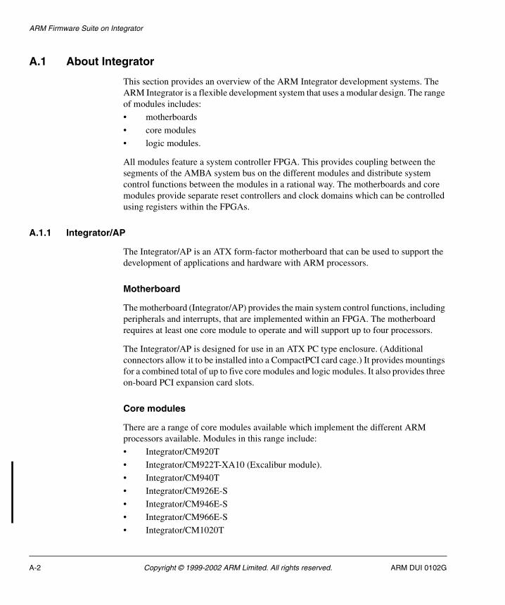
ARM Firmware Suite on Integrator
A.1 About Integrator
This section provides an overview of the ARM Integrator development systems. The ARM Integrator is a flexible development system that uses a modular design. The range of modules includes:
• motherboards
• core modules
• logic modules.
All modules feature a system controller FPGA. This provides coupling between the segments of the AMBA system bus on the different modules and distribute system control functions between the modules in a rational way. The motherboards and core modules provide separate reset controllers and clock domains which can be controlled using registers within the FPGAs.
A.1.1 Integrator/AP
The Integrator/AP is an ATX form-factor motherboard that can be used to support the development of applications and hardware with ARM processors.
Motherboard
The motherboard (Integrator/AP) provides the main system control functions, including peripherals and interrupts, that are implemented within an FPGA. The motherboard requires at least one core module to operate and will support up to four processors.
The Integrator/AP is designed for use in an ATX PC type enclosure. (Additional connectors allow it to be installed into a CompactPCI card cage.) It provides mountings for a combined total of up to five core modules and logic modules. It also provides three on-board PCI expansion card slots.
Core modules
There are a range of core modules available which implement the different ARM processors available. Modules in this range include:
• Integrator/CM920T
• Integrator/CM922T-XA10 (Excalibur module).
• Integrator/CM940T
• Integrator/CM926E-S
• Integrator/CM946E-S
• Integrator/CM966E-S
• Integrator/CM1020T
A-2 Copyright © 1999-2002 ARM Limited. All rights reserved. ARM DUI 0102G

ARM Firmware Suite on Integrator
• Integrator/CM720T
• Integrator/CM740T
• Integrator/CM7TDMI (generic Integrator).
This range allows systems to be modeled with the processor most suited to the target application. All core modules provide volatile memory, clock generation, and reset circuitry. The modules can be used standalone with power and a JTAG debugger, but rely on being installed on a motherboard to access nonvolatile memory and interfaces.
For the Integrator/CM7TDMI, use the generic code found in the Integrator.b or IntegratorT.b subdirectories. For other core modules, use the name of the subdirectory that identifies the board and processor combination. For example, an Integrator with a CM940T uses the source files located in the Integrator940T subdirectories and build files from the Integrator940T.b subdirectories.
Some library code is not specific to an individual processor and uses the generic code in the Integrator subdirectories for all build options.
A.1.2 Integrator/CP
The Integrator/CP is a compact development platform that provides a flexible environment to enable rapid development of ARM-based devices.
There following are variants of the Integrator/CP:
• CP9x6E-S with one of the following cores:
— ARM966E-S
— ARM946E-S (some versions have ETM connections)
• CP920T
• CP922T-XA10
The Integrator/CP comprises two boards:
• the baseboard that provides power, boot memory, and interfaces
• the core module that provides the ARM core, SDRAM, SSRAM, clocks, and an FPGA containing peripheral devices.
Additional peripherals and interfaces can be added to your system by adding up to three logic modules and one interface module.
The core module and baseboard are secured together. This enables you to add and remove additional modules while protecting the connectors on the core module and baseboard from excessive wear. The core module and baseboard boards only operate as a unit and must not be separated.
ARM DUI 0102G Copyright © 1999-2002 ARM Limited. All rights reserved. A-3

ARM Firmware Suite on Integrator
You cannot use more than one core module with the Integrator/CP baseboard.
A.1.3 Logic modules
Logic modules are typically used for system prototyping and debugging. These include:
• Integrator/LM XCV2000E Xilinx logic array.
• Integrator/LM-EP20K1000E Altera logic array.
A.1.4 Build variants
Table A-1 lists the build variants targeted at various Integrator/AP core modules.
If you try to run an incompatible image, for example an Integrator720T image on an ARM940T, the red LED on the Integrator/AP motherboard flashes.
Table A-1 Core module variants
Core module Image type
Integrator Runs on all supported processors (code is based on ARM 7 core)
IntegratorT Runs on all supported processors that can execute Thumb instructions (code is based on ARM 7TDMI core)
Integrator720T ARM720T specific image
Integrator740T ARM740T specific image
Integrator920T ARM920T specific imageARM922TARM926E-S
Integrator940T ARM940T specific image
Integrator946T ARM946E-S specific image
Integrator966T ARM966E-S specific image
Integrator1020T ARM1020T specific image
A-4 Copyright © 1999-2002 ARM Limited. All rights reserved. ARM DUI 0102G

ARM Firmware Suite on Integrator
Boot monitor and Angel variants
There are two variants of Boot Monitor and Angel provided. The only difference between the variants is their execution address:
angIntegrator.axf
Angel image linked to execute at 0x28000000. This address is in motherboard SSRAM on the Integrator/AP. This image will not run on the Integrator/CP.
angIntegrator_SDRAM.axf
Angel image linked to execute in the top 64KB of SDRAM (0x0FFF0000).
bootMonitor.axf
Boot monitor image linked to execute at 0x20000000. This is boot flash on the Integrator/AP, and the last block of flash on the Integrator/CP.
bootMonitor_SDRAM.axf
Boot monitor image linked to execute in the top 128KB of SDRAM (0x100). This image is required for the Integrator/CP because the Integrator/CP contains only one flash device, and the boot monitor cannot run from flash while it is performing flash programming operations.
ARM DUI 0102G Copyright © 1999-2002 ARM Limited. All rights reserved. A-5

ARM Firmware Suite on Integrator
A.2 Integrator-specific commands for boot monitor
The Integrator provides a set of system specific boot monitor commands. These are listed in page A-6. Examples are provided in I, Initialize or re-initialize the PCI subsystem on page A-7 to H or ?, Display help on page A-18. Commands are not case-sensitive.
Table A-2 Integrator system-specific commands
Command Action
I Initialize or re-initialize the PCI subsystem
V Display V3 chip setup
P Display PCI topology
DPI hex Display PCI IO space (32-bit reads)
DPM hex Display PCI Memory space (32-bit reads)
DPC hex Display PCI Configuration space (32-bit reads)
SC module Set clock frequency in SIB
CC Set clocks from SIB
DC Display clock frequencies
DH Display hardware
G hex Go to address
PEEK address Display memory at address (use hex format)
POKE hex data Poke data at address (use hex format for both values)
MEM Enable on-chip memory
ESIB Erase the boot monitor SIB
R i Run image number i from flash
X Exit board-specific command mode
X command Exit board-specific mode or execute single non board-specific command
H or ? Display help
A-6 Copyright © 1999-2002 ARM Limited. All rights reserved. ARM DUI 0102G

ARM Firmware Suite on Integrator
A.2.1 I, Initialize or re-initialize the PCI subsystem
The response to this command depends on the type of Integrator board.
Integrator/AP
This command re-initializes the PCI subsystem. You are prompted to confirm the command before re-initialization is carried out as shown in Example A-1.
Example A-1 Initialize result
[Integrator] boot Monitor > iAbout to re-initialise PCIAre you sure that you want to do this[Yn]? yInitialising PCI...done
Integrator/CP
Prints PCI not supported.
A.2.2 V, Display V3 chip setup
The response to this command depends on the type of Integrator board.
Integrator/AP
This command displays the current set up of the V3 host bridge as shown in Example A-2.
Example A-2 Display V3 result
[Integrator] boot Monitor > vV3 PCI Host Bridge (@ 0x62000000) [0x00000078] SYSTEM : 0xC000(Locked, Reset output de-asserted) [0x0000007C] PCI_CFG : 0x1166 [0x0000007A] LB_CFG : 0x00C0 [0x00000004] PCI_CMD : 0x0006Local --> PCI windows: [0x00000054] LB_BASE0 : 0x40000081 [0x0000005E] LB_MAP0 : 0x4006 [0x00000058] LB_BASE1 : 0x50000081 [0x00000062] LB_MAP1 : 0x5006 [0x00000064] LB_BASE2 : 0x6001
ARM DUI 0102G Copyright © 1999-2002 ARM Limited. All rights reserved. A-7

ARM Firmware Suite on Integrator
[0x00000066] LB_MAP2 : 0x0000PCI --> Local windows: [0x00000010] PCI_IO_BASE : 0x00000000 [0x00000014] PCI_BASE0 : 0x20000000 [0x00000040] PCI_MAP0 : 0x20000093 [0x00000018] PCI_BASE1 : 0x80000000 [0x00000044] PCI_MAP1 : 0x800000A3FIFOs: [0x00000070] FIFO_CFG : 0x0000 [0x00000072] FIFO_PRIORITY: 0x0000 [0x00000074] FIFO_STAT : 0x0505 [0x0000002C] SUB_VENDOR : 0x0000 [0x0000002E] SUB_ID : 0x0000
Integrator/CP
Prints PCI not supported.
A.2.3 P, Display PCI topology
The response to this command depends on the type of Integrator board.
Integrator/AP
This command displays the topology of the PCI subsystem. It lists the devices found and their locations in PCI address space as shown in Example A-3.
Example A-3 PCI topology result
[Integrator] boot Monitor > pBus Slot Func Vendor Device Rev Class Cmd=== ==== ==== ====== ====== ==== ================ ==== 00 12 00 0x10EE 0x3FC2 0x00 Multimedia Audio 0x02
Reg Address Type ==== ========== ====== 0x10 0x40000000 Memory 0x14 0x00000000 Memory 0x18 0x00000000 Memory 0x1C 0x00000000 Memory 0x20 0x00000000 Memory 0x24 0x00000000 Memory 0x30 0x00000000 ROM 0x3D 0x00000001 Interrupt Pin 0x3C 0x00000010 Interrupt Line
A-8 Copyright © 1999-2002 ARM Limited. All rights reserved. ARM DUI 0102G

ARM Firmware Suite on Integrator
Bus Slot Func Vendor Device Rev Class Cmd=== ==== ==== ====== ====== ==== ================ ==== 00 11 00 0x1011 0x0019 0x30 Ethernet 0x07
Reg Address Type ==== ========== ====== 0x10 0x00004000 IO 0x14 0x41000000 Memory 0x18 0x00000000 Memory 0x1C 0x00000000 Memory 0x20 0x00000000 Memory 0x24 0x00000000 Memory 0x30 0x41040000 ROM 0x3D 0x00000001 Interrupt Pin 0x3C 0x0000000F Interrupt Line
Bus Slot Func Vendor Device Rev Class Cmd=== ==== ==== ====== ====== ==== ================ ==== 00 10 00 0x5333 0x88D0 0x00 VGA Device 0x02
Reg Address Type ==== ========== ====== 0x10 0x41800000 Memory 0x14 0x00000000 Memory 0x18 0x00000000 Memory 0x1C 0x00000000 Memory 0x20 0x00000000 Memory 0x24 0x00000000 Memory 0x30 0x42000000 ROM 0x3D 0x00000000 Interrupt Pin 0x3C 0x00000000 Interrupt Line
Bus Slot Func Vendor Device Rev Class Cmd=== ==== ==== ====== ====== ==== ================ ==== 00 09 00 0x1011 0x0024 0x03 PCI->PCI Bridge 0x07
Reg Address Type ==== ========== ====== 0x10 0x00000000 Memory 0x14 0x00000000 Memory 0x18 0x00010100 Memory 0x1C 0x02804150 IO 0x20 0x42004210 Memory 0x24 0x00010000 IO 0x30 0x00000000 ROM
ARM DUI 0102G Copyright © 1999-2002 ARM Limited. All rights reserved. A-9
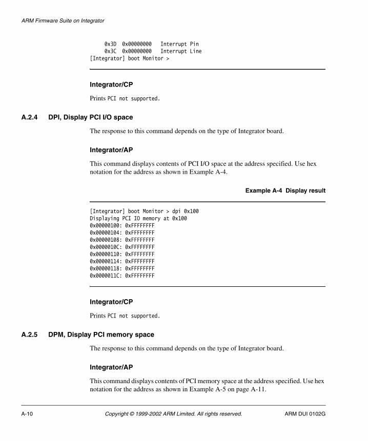
ARM Firmware Suite on Integrator
0x3D 0x00000000 Interrupt Pin 0x3C 0x00000000 Interrupt Line[Integrator] boot Monitor >
Integrator/CP
Prints PCI not supported.
A.2.4 DPI, Display PCI I/O space
The response to this command depends on the type of Integrator board.
Integrator/AP
This command displays contents of PCI I/O space at the address specified. Use hex notation for the address as shown in Example A-4.
Example A-4 Display result
[Integrator] boot Monitor > dpi 0x100Displaying PCI IO memory at 0x1000x00000100: 0xFFFFFFFF0x00000104: 0xFFFFFFFF0x00000108: 0xFFFFFFFF0x0000010C: 0xFFFFFFFF0x00000110: 0xFFFFFFFF0x00000114: 0xFFFFFFFF0x00000118: 0xFFFFFFFF0x0000011C: 0xFFFFFFFF
Integrator/CP
Prints PCI not supported.
A.2.5 DPM, Display PCI memory space
The response to this command depends on the type of Integrator board.
Integrator/AP
This command displays contents of PCI memory space at the address specified. Use hex notation for the address as shown in Example A-5 on page A-11.
A-10 Copyright © 1999-2002 ARM Limited. All rights reserved. ARM DUI 0102G

ARM Firmware Suite on Integrator
Example A-5 Display PCI memory result
[Integrator] boot Monitor > dpm 0x100Displaying PCI Memory at 0x1000x00000100: 0x000023780x00000104: 0x20000D5C0x00000108: 0x20000D600x0000010C: 0x200016D00x00000110: 0x20000D700x00000114: 0x20000D740x00000118: 0x200016D00x0000011C: 0x20000D84
Integrator/CP
Prints PCI not supported.
A.2.6 DPC, Display PCI configuration space
The response to this command depends on the type of Integrator board.
Integrator/AP
This command displays contents of PCI configuration space at the address specified. Use hex notation for the address as shown in Example A-6.
Example A-6 Display PCI configuration result
[Integrator] boot Monitor > dpc 0x100Displaying PCI Configuration memory at 0x1000x00000100: 0xFFFFFFFF0x00000104: 0xFFFFFFFF0x00000108: 0xFFFFFFFF0x0000010C: 0xFFFFFFFF0x00000110: 0xFFFFFFFF0x00000114: 0xFFFFFFFF0x00000118: 0xFFFFFFFF0x0000011C: 0xFFFFFFFF
Integrator/CP
Prints PCI not supported.
ARM DUI 0102G Copyright © 1999-2002 ARM Limited. All rights reserved. A-11

ARM Firmware Suite on Integrator
A.2.7 CC, Set clocks from SIB
Enter the command CC to activate the settings from the boot monitor SIB. This copies the clock settings from the SIB into the relevant hardware registers. If the exact frequency values cannot be set due to dependencies within the core, a message is displayed indicating the value used. See Example A-7. See also DC, Display clock frequencies and SC, Set clock frequencies in SIB on page A-14.
Example A-7 Set clocks from SIB (Integrator/AP)
[Integrator] boot Monitor > ccSetting clocks on core module 0
On the Integrator/CP, this command might reset the board.
Example A-8 Set clocks from SIB (Integrator/CP)
[Integrator] boot Monitor > ccThis may reset the system...Setting clocks on core module 0
You are recommended to use this command after using SC to change the clock settings to ensure that they work correctly on the hardware in use. Using the SC and CC command to increase the clock settings also improves the performance of the S-record loader, particularly at higher line speeds.
A.2.8 DC, Display clock frequencies
Displays the both the current clock settings and the clock settings stored in the boot monitor SIB. If more than one core module is attached, the settings for each core module is displayed.
Integrator/AP has two programmable system clocks:
• system bus clock
• PCI clock.
A-12 Copyright © 1999-2002 ARM Limited. All rights reserved. ARM DUI 0102G

ARM Firmware Suite on Integrator
Each core module has two or three programmable clocks:
• core clock
• local memory bus clock (on some cores this is not independent of the core clock)
• local internal bus clock (this is not present on all cores).
The boot monitor stores settings for the clocks in the SIB. Use the DC command to display both the current and stored SIB settings (see Example A-9).
Example A-9 Display settings (Integrator/AP)
[Integrator] boot Monitor > dc
Core Module Clocks================== ------ SIB ----- ---- Current ---CM Core Type Core IBus LBus Core IBus LBus PLL-- --------- ---- ---- ---- ---- ---- ---- ---0 ARM966 60 - 30 120 - 40 Off
LBus = Local Memory BusIBus = Internal Bus
System Clocks============= ------ SIB ----- ---- Current --- System Bus PCI System Bus PCI ---------- --- ---------- --- 20 33 20 33
On the Integrator/CP, only the core module clocks are displayed (see Example A-10).
Example A-10 Display settings (Integrator/CP)
[Integrator] boot Monitor > dc
Core Module Clocks================== ------ SIB ----- ---- Current ---CM Core Type Core IBus LBus Core IBus LBus PLL-- --------- ---- ---- ---- ---- ---- ---- ---0 ARM966 120 - 30 60 - 30 Off
ARM DUI 0102G Copyright © 1999-2002 ARM Limited. All rights reserved. A-13
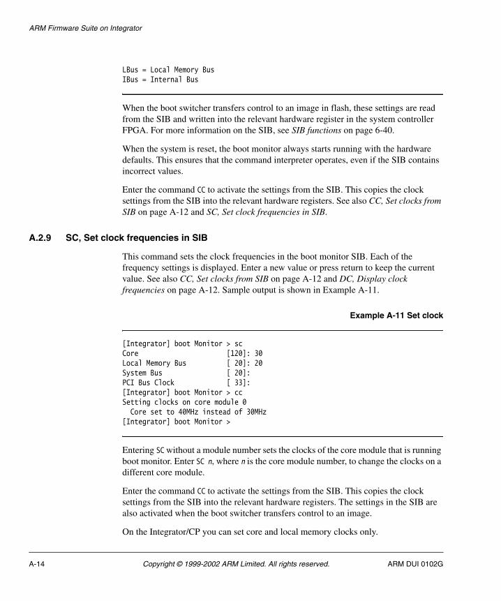
ARM Firmware Suite on Integrator
LBus = Local Memory BusIBus = Internal Bus
When the boot switcher transfers control to an image in flash, these settings are read from the SIB and written into the relevant hardware register in the system controller FPGA. For more information on the SIB, see SIB functions on page 6-40.
When the system is reset, the boot monitor always starts running with the hardware defaults. This ensures that the command interpreter operates, even if the SIB contains incorrect values.
Enter the command CC to activate the settings from the SIB. This copies the clock settings from the SIB into the relevant hardware registers. See also CC, Set clocks from SIB on page A-12 and SC, Set clock frequencies in SIB.
A.2.9 SC, Set clock frequencies in SIB
This command sets the clock frequencies in the boot monitor SIB. Each of the frequency settings is displayed. Enter a new value or press return to keep the current value. See also CC, Set clocks from SIB on page A-12 and DC, Display clock frequencies on page A-12. Sample output is shown in Example A-11.
Example A-11 Set clock
[Integrator] boot Monitor > sc Core [120]: 30Local Memory Bus [ 20]: 20System Bus [ 20]:PCI Bus Clock [ 33]:[Integrator] boot Monitor > ccSetting clocks on core module 0 Core set to 40MHz instead of 30MHz[Integrator] boot Monitor >
Entering SC without a module number sets the clocks of the core module that is running boot monitor. Enter SC n, where n is the core module number, to change the clocks on a different core module.
Enter the command CC to activate the settings from the SIB. This copies the clock settings from the SIB into the relevant hardware registers. The settings in the SIB are also activated when the boot switcher transfers control to an image.
On the Integrator/CP you can set core and local memory clocks only.
A-14 Copyright © 1999-2002 ARM Limited. All rights reserved. ARM DUI 0102G
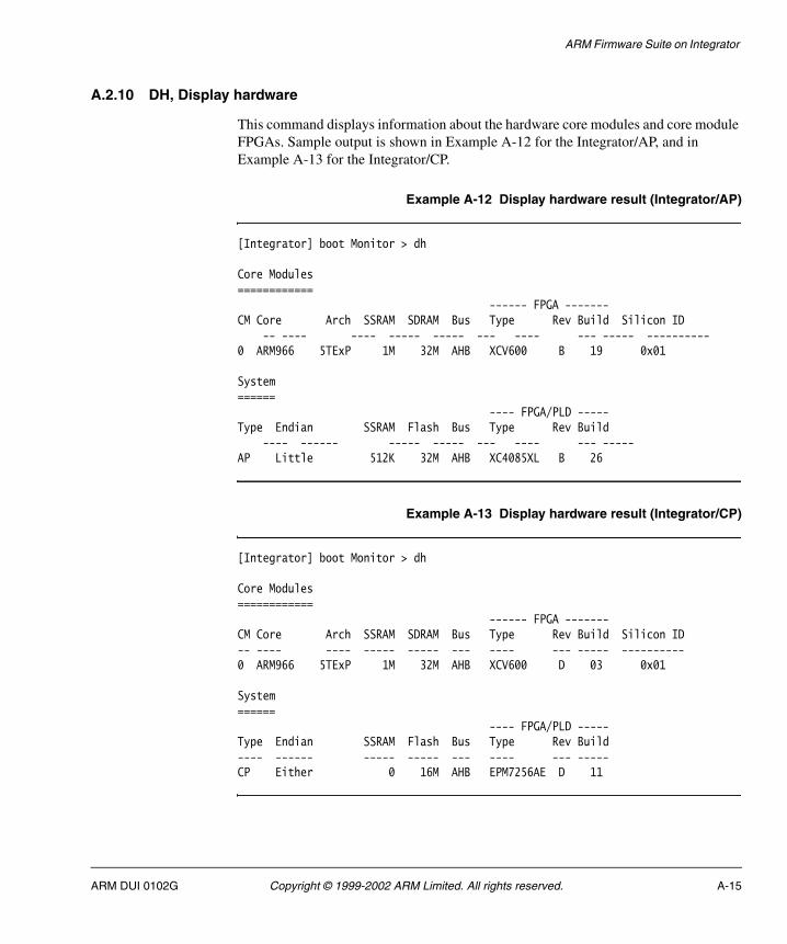
ARM Firmware Suite on Integrator
A.2.10 DH, Display hardware
This command displays information about the hardware core modules and core module FPGAs. Sample output is shown in Example A-12 for the Integrator/AP, and in Example A-13 for the Integrator/CP.
Example A-12 Display hardware result (Integrator/AP)
[Integrator] boot Monitor > dh
Core Modules============ ------ FPGA -------CM Core Arch SSRAM SDRAM Bus Type Rev Build Silicon ID
-- ---- ---- ----- ----- --- ---- --- ----- ----------0 ARM966 5TExP 1M 32M AHB XCV600 B 19 0x01
System======
---- FPGA/PLD -----Type Endian SSRAM Flash Bus Type Rev Build
---- ------ ----- ----- --- ---- --- -----AP Little 512K 32M AHB XC4085XL B 26
Example A-13 Display hardware result (Integrator/CP)
[Integrator] boot Monitor > dh
Core Modules============
------ FPGA -------CM Core Arch SSRAM SDRAM Bus Type Rev Build Silicon ID-- ---- ---- ----- ----- --- ---- --- ----- ----------0 ARM966 5TExP 1M 32M AHB XCV600 D 03 0x01
System======
---- FPGA/PLD -----Type Endian SSRAM Flash Bus Type Rev Build---- ------ ----- ----- --- ---- --- -----CP Either 0 16M AHB EPM7256AE D 11
ARM DUI 0102G Copyright © 1999-2002 ARM Limited. All rights reserved. A-15
ARM Firmware Suite on Integrator
Details of each field are as follows:
Core Module CM Core Module.
Core Core name (as decoded from system identification register).
Arch Architecture version of the code.
SSRAM Amount of SSRAM fitted.
SDRAM Amount od SDRAM fitted.
Bus Bus type of the local memory bus.
FPGA Type FPGA Part number.
FPGA Rev/Build Rev and build information of the FPGA.
Silicon ID Silicon identification as read from the CM_STAT register.
System Type AP or CP.
Endian One of Little, Big, or Either depending on the endian support of the system.
SSRAM Amount of SSRAM fitted to the motherboard.
Flash Amount of Flash fitted to the motherboard/baseboard.
Bus Bus type of the system bus.
FPGA/PLD Type FPGA/PLD Part number.
FPGA/PLD Rev/Build Rev and build information of the FPGA.
Note The core module bus field refers to the bus local to the core module. This is also called the local memory bus. The system bus field refers to the system bus. The type of bus may be different. Upgrading the system with the AHB support supplied with AFS only changes the type of the system bus. Existing core modules can be upgraded to change the bridge between the local memory bus and system bus from ASB-ASB to ASB-AHB. The local memory bus remains unchanged.
A.2.11 G, Go to address
This command transfers control to the address supplied. Use hex notation for the address.
A-16 Copyright © 1999-2002 ARM Limited. All rights reserved. ARM DUI 0102G

ARM Firmware Suite on Integrator
A.2.12 X, Exit board-specific command mode
Enter a single x to exit the board-specific command mode. Enter x followed by a command to execute a single command and then return to board-specific mode.
A.2.13 PEEK, Display memory at address
This command displays the contents of memory. Sample output is shown in Example A-14.
Example A-14 Peek
[Integrator] boot Monitor > peek 0x01000000Displaying memory at 0x010000000x01000000: C80000000x01000004: 001800C10x01000008: 001801010x0100000C: 002000000x01000010: 008100C00x01000014: 2C0305000x01000018: 00882A900x0100001C: 00040D78[Integrator] boot Monitor >
A.2.14 POKE, Write memory at address
This command inserts the hex word data at the hex address in memory. Sample output is shown in Example A-15.
Example A-15 Poke
[Integrator] boot Monitor > poke 0x01000010 0x12345678Poking memory at 0x01000010 with value 0x12345678[Integrator] boot Monitor >
A.2.15 MEM, Enable on-chip memory
This command writes to the boot monitor SIB to instruct the boot switcher to enable on-chip memory before an image is relocated from flash. A correctly linked image will then be copied into, and erased from, the on-chip memory.
This command is only supported with the ARM966 series core modules.
ARM DUI 0102G Copyright © 1999-2002 ARM Limited. All rights reserved. A-17
ARM Firmware Suite on Integrator
A.2.16 ESIB, Erase SIB
This command erases the boot monitor SIB.
A new SIB will be created with default values when any other command that references the SIB (for example DC) is executed.
A.2.17 R, Run image from flash
This command transfers control to image number in flash. The image number is the logical image number, and is not based on the order of the images in flash.
A.2.18 H or ?, Display help
This command lists the full set of board-specific commands for this mode.
A-18 Copyright © 1999-2002 ARM Limited. All rights reserved. ARM DUI 0102G
ARM Firmware Suite on Integrator
A.3 Using the boot monitor on Integrator
This section describes how to use the system-specific aspects of the boot monitor on Integrator. This includes specific boot monitor commands, boot switcher, and hardware features as they affect components of the AFS.
See also Integrator-specific commands for boot monitor on page A-6.
A.3.1 Flash on Integrator
Integrator has two separate areas of flash designated as boot flash and application flash. Table A-3 provides a summary of these flash areas.
Integrator/AP Application flash
The Integrator/AP application flash is a general purpose area that you can use to store any images or data that must be held in nonvolatile memory. The ARM Flash Library implements a simple mechanism for storing multiple images in flash. This structure enables the boot switcher to select and run the correct boot image. The ARM Flash Utility uses the flash library to program and delete images in application flash. In Table A-3, a block is defined as the smallest area of flash that can be independently deleted. The flash library supports storing an image in either a single block or in contiguous multiple blocks.
Integrator/AP Boot flash
The Integrator/AP boot flash contains the default application (usually the boot monitor), boot switcher, and the FPGA image for the system controller.
Table A-3 Flash device usage on Integrator
Device Size Organization Flash part Usage
Integrator/AP Boot flash
512KB 1x512K block Atmel AT49LV040 Boot monitor System Controller FPGA image
Integrator/AP Application flash
32MB 256x128K blocks Intel 28F320S3 Angel, applications, and data
Integrator/CP Boot/Application flash
16MB 64x256K blocks Intel 28F640J3A Block 0-62 - Applications
Block 63 - Boot Monitor
ARM DUI 0102G Copyright © 1999-2002 ARM Limited. All rights reserved. A-19

ARM Firmware Suite on Integrator
Caution This device can be reprogrammed using BootFU. However, you must take care as incorrect programming can corrupt the FPGA image and prevent the system from booting. If the system controller FPGA image is corrupted, you must reprogram the boot flash using the JTAG connector and Multi-ICE.
In the Images\Integrator subdirectory are files called bootPROM_AHB.mcs and bootPROM_ASB.mcs. These are Intel hex format images that include both the boot monitor and the system controller FPGA image. If the FPGA becomes corrupted, you can use this to reprogram the boot flash over the JTAG connector.
Location of images in flash
The normal location for Angel is block 1 in the boot flash. However, because Angel relocates itself to SDRAM there is no restriction on its location in flash. Run the Angel image by selecting image 911 as the boot image and using the boot-from-flash switches.
The standalone variants of the µHAL demo programs are built to run from block 64 of application flash (0x24800000). You can change this by changing the read-only base address when linking the image. If the read-only base is an address in RAM the boot switcher copies the image into RAM before transferring control to it.
A.3.2 Boot switcher
The boot switcher routine is embedded in the boot monitor and is the first thing that is run after the board is powered on. It reads switch S1-1 and if it is OFF, the boot switcher attempts to find and run the default image in flash.
If S1-1 is ON, control depends on the setting of switch S1-4. The boot monitor is run if S1-4 is ON and the selected boot image if it is OFF. This is summarized in Table A-4.
Table A-4 Boot switch settings
S1-1 S1-4 Action
OFF ON or OFF Runs default application flash image at 0x24000000
ON ON System runs boot monitor
ON OFF System runs selected boot image
A-20 Copyright © 1999-2002 ARM Limited. All rights reserved. ARM DUI 0102G

ARM Firmware Suite on Integrator
A.3.3 Safe mode
If switch S1-2 is ON, the boot monitor runs in safe mode. This means:
• Phase Locked Loop (PLL) is not enabled.
• The PS/2 keyboard controller is not initialized.
• VGA output is disabled.
A.3.4 Integrator clocks
The boot monitor stores settings for the clocks in the SIB. You can modify and display them using the boot monitor command interpreter (see CC, Set clocks from SIB on page A-12).
A.3.5 LEDs
If the boot switcher is unable to find or run an image in flash, the red LED on the motherboard is illuminated.
If an attempt is made to run a µHAL image that is not compatible with the hardware (for example, an image built for an ARM720T is run on an ARM920T) the red LED flashes at one-second intervals.
On the Integrator/CP, the boot monitor requires that a SDRAM is fitted. If no SDRAM is found, alpha LEDs will display SD.
A.3.6 Multiple core modules with the Integrator/AP
You can fit the Integrator/AP with up to four core modules. Each one is equipped with a processor. If more than one core module is fitted to the Integrator motherboard, the boot monitor only runs on the primary processor (on core module 0).
Note You cannot use multiple core modules with the Integrator/CP.
Some commands display additional information when multiple cores are present:
DH Display hardware shows details of each core module in the system, including the core type, SSRAM and SDRAM fitted and FPGA version.
ARM DUI 0102G Copyright © 1999-2002 ARM Limited. All rights reserved. A-21
ARM Firmware Suite on Integrator
DC Display clocks displays both the current and SIB clock settings for all core modules in the system. There are three clocks reported for each core module, these are the core clock, core module bus clock and internal bus clock. Not all core modules support all these clocks, for example currently the only core module that has an internal bus is the CM10200. Where a particular core module does not support a clock it is reported as -1.
SC Set clocks prompts for the appropriate clock for the core module and writes these values into the SIB. By default, this command prompts for the clocks for the core module the boot monitor is running on and the two system clocks (system bus and PCI). However, it can be used to set the clock for another core module by specifying the core module number on the command (for example, SC 2 to set the clocks for core module 2).
CC Set clocks from SIB sets the clocks using the data from the SIB for all the core modules in the system, the system bus, and PCI clocks.
A.3.7 Loading images using the boot monitor
To load images using Motorola 32 S-record loader, you need a terminal emulator that can send raw ASCII data files. In the ARM Firmware Suite, Motorola 32 S-record images are built with the .m32 file extension. There are no prebuilt Motorola 32 S-record Angel images.
You can build Motorola 32 S-record files for other images such as, for example, the standalone µHAL demo programs, using the FromELF utility.
Use the Motorola 32 S-record loader as follows:
1. Set your terminal emulator to enable XON/XOFF flow control.
2. Reset the Integrator system with both switches S1-1 and S1-4 in the ON position. This causes the boot monitor command interpreter to run.
3. At the command prompt type L to start the Motorola 32 S-record loader. The following dialog is displayed:
boot Monitor > lLoad Motorola S Records into flashDeleting Image 0Type Ctrl/C to exit loader.
Any image the boot monitor loads is numbered image 0. If an image 0 already exists, it is deleted first.
4. Use the send file option on your terminal emulator to download the Motorola 32 S-record image.
A-22 Copyright © 1999-2002 ARM Limited. All rights reserved. ARM DUI 0102G

ARM Firmware Suite on Integrator
The boot monitor transmits a dot for every 64 records received from the terminal emulator.
5. When the terminal emulator has finished sending the file, type Ctrl+C to exit the loader. On exit the loader displays the number of records loaded, the time the load took. It also lists any blocks it has overwritten.
6. Enter BI 0 to select image number 0 as the image to run on reset.
7. Now move switch S1-4 to the OFF position and reset the system to run the image.
After the boot monitor has loaded the image, it sets the boot image number to 0. When the system restarts, the boot switcher finds and boots the last image loaded.
Note Many of the newer development boards have Angel preloaded in ROM as image number 911.
ARM DUI 0102G Copyright © 1999-2002 ARM Limited. All rights reserved. A-23

ARM Firmware Suite on Integrator
A.4 Angel on Integrator
This section provides an overview of Angel on the ARM Integrator development system. You can use Angel to load and debug programs over a serial port.
A.4.1 Location in memory
There are two variants of Angel supplied, linked with different execution addresses.
angIntegrator.axf (Integrator/AP only)
The angIntegrator.axf variant of Angel is linked to run at address 0x28000000. This is in the motherboard SSRAM. The image itself is stored in boot flash. Execution starts in boot flash, and the image relocates itself to the motherboard SSRAM.
The Integrator/CP cannot run angIntegrator.axf.
angIntegrator_SDRAM.axf (Integrator/AP and Integrator/CP)
The angIntegrator_SDRAM.axf variant of Angel is linked to run at address 0x20000000. This is the top 64KB of SDRAM on the Integrator/CP (0x0FFF000).
You can run angIntegrator_SDRAM.axf on both the Integrator/CP and Integrator/AP.
A.4.2 Caches
Angel for Integrator runs without enabling caches. To get the maximum performance from the system, you must enable caches. This requirement on the application is also true for Multi-ICE. See uHALr_EnableCache() on page 2-12 for details on enabling caches.
Applications built against µHAL can use µHAL functions to control the cache. See Simple API MMU and cache functions on page 2-11 and Extended API MMU and cache functions on page 2-39.
A.4.3 Line speed
The maximum line speed that Angel supports depends on factors such as the clock settings for the processor and buses. A maximum line speed of 38,400bps is supported for a system with the optimum clock settings and caches disabled.
A-24 Copyright © 1999-2002 ARM Limited. All rights reserved. ARM DUI 0102G
ARM Firmware Suite on Integrator
A.4.4 Downloading Angel
The Integrator boards normally have Angel preinstalled in the flash memory boot ROM. If you have rebuilt the Angel image, use the boot monitor to load the new image as image 0 or use BootFU to load the image as image 911.
ARM DUI 0102G Copyright © 1999-2002 ARM Limited. All rights reserved. A-25

ARM Firmware Suite on Integrator
A.5 PCI initialization on Integrator (Integrator/AP only)
The Integrator/AP system uses a V3 Semiconductor V360EPC to provide PCI host bridge support. The system-specific µHAL code must initialize this device and provide PCI access mechanisms.
A.5.1 Integrator PCI subsystem overview
The V3 PCI interface chip in an Integrator provides several windows from local bus memory into the PCI memory areas. Because there are too few windows, one of the windows is reused for access to PCI configuration space. The memory map is shown in Table A-5.
There are three V3 windows, each described by a pair of V3 registers. These are:
• LB_BASE0 and LB_MAP0
• LB_BASE1 and LB_MAP1
• LB_BASE2 and LB_MAP2.
You can use Base0 and Base1 for any type of PCI memory access. You can use Base2 either for PCI I/O or for I20 accesses. By default, µHAL uses this only for PCI I/O space.
Note PCI Memory is mapped so that assigned addresses in PCI memory match local bus memory addresses.
If a PCI device is assigned address 0x40200000, that address is a valid local bus address as well as a valid PCI memory address. PCI I/O addresses are mapped to start at 0. This means that local bus address 0x60000000 maps to PCI I/O address 0x00000000 for example.
Table A-5 PCI memory map
Local bus memory Function Size
0x40000000 – 0x4FFFFFFF PCI memory, nonprefetchable 256MB
0x50000000 – 0x5FFFFFFF PCI memory, prefetchable 256MB
0x60000000 – 0x60FFFFFF PCI I/O 16MB
0x61000000 – 0x61FFFFFF PCI Configuration 16MB
0x62000000 V3 internal registers -
A-26 Copyright © 1999-2002 ARM Limited. All rights reserved. ARM DUI 0102G
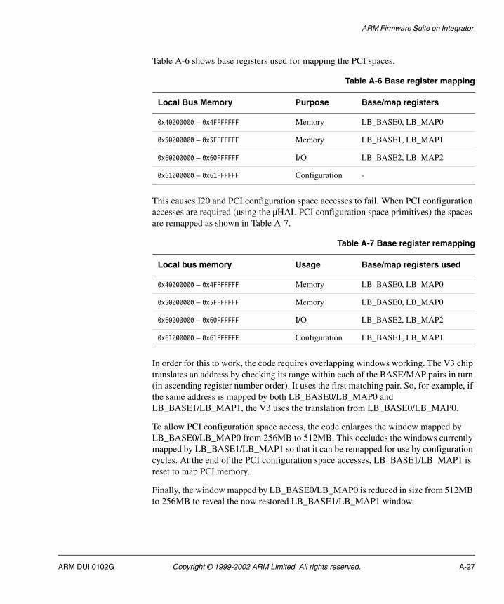
ARM Firmware Suite on Integrator
Table A-6 shows base registers used for mapping the PCI spaces.
This causes I20 and PCI configuration space accesses to fail. When PCI configuration accesses are required (using the µHAL PCI configuration space primitives) the spaces are remapped as shown in Table A-7.
In order for this to work, the code requires overlapping windows working. The V3 chip translates an address by checking its range within each of the BASE/MAP pairs in turn (in ascending register number order). It uses the first matching pair. So, for example, if the same address is mapped by both LB_BASE0/LB_MAP0 and LB_BASE1/LB_MAP1, the V3 uses the translation from LB_BASE0/LB_MAP0.
To allow PCI configuration space access, the code enlarges the window mapped by LB_BASE0/LB_MAP0 from 256MB to 512MB. This occludes the windows currently mapped by LB_BASE1/LB_MAP1 so that it can be remapped for use by configuration cycles. At the end of the PCI configuration space accesses, LB_BASE1/LB_MAP1 is reset to map PCI memory.
Finally, the window mapped by LB_BASE0/LB_MAP0 is reduced in size from 512MB to 256MB to reveal the now restored LB_BASE1/LB_MAP1 window.
Table A-6 Base register mapping
Local Bus Memory Purpose Base/map registers
0x40000000 – 0x4FFFFFFF Memory LB_BASE0, LB_MAP0
0x50000000 – 0x5FFFFFFF Memory LB_BASE1, LB_MAP1
0x60000000 – 0x60FFFFFF I/O LB_BASE2, LB_MAP2
0x61000000 – 0x61FFFFFF Configuration -
Table A-7 Base register remapping
Local bus memory Usage Base/map registers used
0x40000000 – 0x4FFFFFFF Memory LB_BASE0, LB_MAP0
0x50000000 – 0x5FFFFFFF Memory LB_BASE0, LB_MAP0
0x60000000 – 0x60FFFFFF I/O LB_BASE2, LB_MAP2
0x61000000 – 0x61FFFFFF Configuration LB_BASE1, LB_MAP1
ARM DUI 0102G Copyright © 1999-2002 ARM Limited. All rights reserved. A-27

ARM Firmware Suite on Integrator
Note I20 mapping is not set up because using I2O disables most of the mappings into PCI memory.
A.5.2 Initializing the host bridge
The PCI initialization code is an assembly macro in target.s. Example A-16 shows the code.
Example A-16 PCI initilization code
; NOTE: load $w1 with the base address of the V3's register set ; at the start of the macro and expect it not to change! MACRO$label SETUP_PCI $w1, $w2, $w3, $w4
; first turn on PCI LDR $w1, =INTEGRATOR_SC_PCIENABLE LDR $w2, =0x1 STR $w2, [$w1] ; Load up the base address of the V3 register set LDR $w1, =PCI_V3_BASE
; can NOT try ANY reads from the V3 bridge chip until LB_IO_BASE is written ; we ASSUME that we've already waited for >=230us (@PCLK 25MHz) since reset ; so that this write WILL have an effect on the V3 chip ; Set up where the V3 registers appear in the memory map (PCI_V3_BASE) LDR $w2, =PCI_V3_BASE MOV $w2, $w2, LSR #16 STRH $w2, [$w1, #V3_LB_IO_BASE]
; Wait for the V3 to realise that there is no SROM LDR $w2, =0xAA LDR $w3, =0x5530 STRB $w2, [$w1, #V3_MAIL_DATA] STRB $w3, [$w1, #V3_MAIL_DATA + 4] LDRB $w4, [$w1, #V3_MAIL_DATA] CMP $w4, #0xAA BNE %b30 LDRB $w4, [$w1, #V3_MAIL_DATA + 4] CMP $w4, #0x55 BNE %b30
; Make sure that V3 register access is not locked, if it is, unlock it. LDRH $w2, [$w1, #V3_SYSTEM]
A-28 Copyright © 1999-2002 ARM Limited. All rights reserved. ARM DUI 0102G

ARM Firmware Suite on Integrator
AND $w2, $w2, #V3_SYSTEM_M_LOCK CMP $w2, #V3_SYSTEM_M_LOCK LDREQ $w2, =0xA05F STREQH $w2, [$w1, #V3_SYSTEM]
; ensure that slave accesses from PCI are DISabled while we set up windows LDRH $w2, [$w1, #V3_PCI_CMD] ; get current CMD register BIC $w2, $w2, #(V3_COMMAND_M_MEM_EN :OR: V3_COMMAND_M_IO_EN) STRH $w2, [$w1, #V3_PCI_CMD] ; MEM & IO now BOTH bounce
; Clear RST_OUT to 0: keep the PCI bus in reset until we're finished LDRH $w2, [$w1, #V3_SYSTEM] BIC $w2, $w2, #V3_SYSTEM_M_RST_OUT STRH $w2, [$w1, #V3_SYSTEM] ; Make all accesses from PCI space retry until we're ready for them LDRH $w2, [$w1, #V3_PCI_CFG] ORR $w2, $w2, #V3_PCI_CFG_M_RETRY_EN STRH $w2, [$w1, #V3_PCI_CFG]
; Set up any V3 PCI Configuration Registers that we absolutely have to ; LB_CFG controls Local Bus protocol. ; enable LocalBus byte strobes for READ accesses too LDRH $w2, [$w1, #V3_LB_CFG] ORR $w2, $w2, #0x0C0 ; set bit7 BE_IMODE & bit6 BE_OMODE STRH $w2, [$w1, #V3_LB_CFG]
; PCI_CMD controls overall PCI operation ; enable PCI bus master; ; for memory but NOT I/O LDRH $w2, [$w1, #V3_PCI_CMD] ORR $w2, $w2, #0x04 ; set bit2 MASTER_EN STRH $w2, [$w1, #V3_PCI_CMD]
; PCI_HDR_CFG controls PCI master timeouts etc. ; PCI_SUB_VENDOR contains an info field for other masters
; PCI_SUB_ID contains an info field for other masters
; PCI_MAP0 controls where the PCI to CPU memory window is on the Local Bus LDR $w2, =INTEGRATOR_BOOT_ROM_BASE ; start of EBI memory MOV $w2, $w2, LSR #20 ; clip to 12-bit field MOV $w2, $w2, LSL #20 ; at top of word wide reg ; aperture size is 512M ORR $w2, $w2, #V3_PCI_MAP_M_ADR_SIZE_512M ; PCI_BASE0 reg MUST be enabled before writing it ; aperture itself enabled too ORR $w2, $w2, #V3_PCI_MAP_M_REG_EN :OR: V3_PCI_MAP_M_ENABLE STR $w2, [$w1, #V3_PCI_MAP0] ; finally write the reg ; PCI_BASE0 is the PCI address of the start of the window
ARM DUI 0102G Copyright © 1999-2002 ARM Limited. All rights reserved. A-29
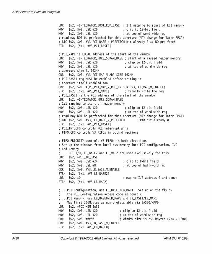
ARM Firmware Suite on Integrator
LDR $w2, =INTEGRATOR_BOOT_ROM_BASE ; 1:1 mapping to start of EBI memory MOV $w2, $w2, LSR #20 ; clip to 12-bit field MOV $w2, $w2, LSL #20 ; at top of word wide reg ; read may NOT be prefetched for this aperture (MAY change for later FPGA) ; BIC $w2, $w2, #V3_PCI_BASE_M_PREFETCH bit already 0 => NO pre-fetch STR $w2, [$w1, #V3_PCI_BASE0]
; PCI_MAP1 is LOCAL address of the start of the window LDR $w2, =INTEGRATOR_HDR0_SDRAM_BASE ; start of aliassed header memory MOV $w2, $w2, LSR #20 ; clip to 12-bit field MOV $w2, $w2, LSL #20 ; at top of word wide reg ; aperture size is 1024M ORR $w2, $w2, #V3_PCI_MAP_M_ADR_SIZE_1024M ; PCI_BASE1 reg MUST be enabled before writing it ; aperture itself enabled too ORR $w2, $w2, #(V3_PCI_MAP_M_REG_EN :OR: V3_PCI_MAP_M_ENABLE) STR $w2, [$w1, #V3_PCI_MAP1] ; finally write the reg ; PCI_BASE1 is the PCI address of the start of the window LDR $w2, =INTEGRATOR_HDR0_SDRAM_BASE ; 1:1 mapping to start of header memory MOV $w2, $w2, LSR #20 ; clip to 12-bit field MOV $w2, $w2, LSL #20 ; at top of word wide reg ; read may NOT be prefetched for this aperture (MAY change for later FPGA) ; BIC $w2, $w2, #V3_PCI_BASE_M_PREFETCH ;### bit already 0 STR $w2, [$w1, #V3_PCI_BASE1] ; PCI_INT_CFG controls PCI interrupt pins ; FIFO_CFG controls V3 FIFOs in both directions
; FIFO_PRIORITY controls V3 FIFOs in both directions ; Set up the windows from local bus memory into PCI configuration, I/O ; and Memory ; ... PCI I/O, LB_BASE2 and LB_MAP2 are used exclusively for this LDR $w2, =PCI_IO_BASE MOV $w2, $w2, LSR #24 ; clip to 8-bit field MOV $w2, $w2, LSL #8 ; at top of half-word reg ORR $w2, $w2, #V3_LB_BASE_M_ENABLE STRH $w2, [$w1, #V3_LB_BASE2] LDR $w2, =0 ; map to I/0 address 0 and above STRH $w2, [$w1, #V3_LB_MAP2]
; ...PCI Configuration, use LB_BASE1/LB_MAP1. Set up on the fly by ; the PCI Configuration access code in board.c ; ...PCI Memory, use LB_BASE0/LB_MAP0 and LB_BASE1/LB_MAP1 ; Map first 256Mbytes as non-prefetchable via BASE0/MAP0 LDR $w2, =PCI_MEM_BASE MOV $w2, $w2, LSR #20 ; clip to 12-bit field MOV $w2, $w2, LSL #20 ; at top of word wide reg ORR $w2, $w2, #0x80 ; Window size is 256 Mbytes (7:4 = 1000) ORR $w2, $w2, #V3_LB_BASE_M_ENABLE STR $w2, [$w1, #V3_LB_BASE0]
A-30 Copyright © 1999-2002 ARM Limited. All rights reserved. ARM DUI 0102G
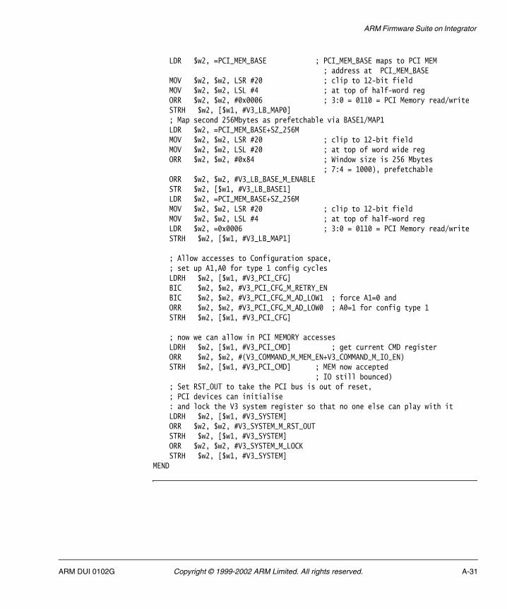
ARM Firmware Suite on Integrator
LDR $w2, =PCI_MEM_BASE ; PCI_MEM_BASE maps to PCI MEM ; address at PCI_MEM_BASE MOV $w2, $w2, LSR #20 ; clip to 12-bit field MOV $w2, $w2, LSL #4 ; at top of half-word reg ORR $w2, $w2, #0x0006 ; 3:0 = 0110 = PCI Memory read/write STRH $w2, [$w1, #V3_LB_MAP0] ; Map second 256Mbytes as prefetchable via BASE1/MAP1 LDR $w2, =PCI_MEM_BASE+SZ_256M MOV $w2, $w2, LSR #20 ; clip to 12-bit field MOV $w2, $w2, LSL #20 ; at top of word wide reg ORR $w2, $w2, #0x84 ; Window size is 256 Mbytes ; 7:4 = 1000), prefetchable ORR $w2, $w2, #V3_LB_BASE_M_ENABLE STR $w2, [$w1, #V3_LB_BASE1] LDR $w2, =PCI_MEM_BASE+SZ_256M MOV $w2, $w2, LSR #20 ; clip to 12-bit field MOV $w2, $w2, LSL #4 ; at top of half-word reg LDR $w2, =0x0006 ; 3:0 = 0110 = PCI Memory read/write STRH $w2, [$w1, #V3_LB_MAP1]
; Allow accesses to Configuration space, ; set up A1,A0 for type 1 config cycles LDRH $w2, [$w1, #V3_PCI_CFG] BIC $w2, $w2, #V3_PCI_CFG_M_RETRY_EN BIC $w2, $w2, #V3_PCI_CFG_M_AD_LOW1 ; force A1=0 and ORR $w2, $w2, #V3_PCI_CFG_M_AD_LOW0 ; A0=1 for config type 1 STRH $w2, [$w1, #V3_PCI_CFG]
; now we can allow in PCI MEMORY accesses LDRH $w2, [$w1, #V3_PCI_CMD] ; get current CMD register ORR $w2, $w2, #(V3_COMMAND_M_MEM_EN+V3_COMMAND_M_IO_EN) STRH $w2, [$w1, #V3_PCI_CMD] ; MEM now accepted ; IO still bounced) ; Set RST_OUT to take the PCI bus is out of reset, ; PCI devices can initialise : and lock the V3 system register so that no one else can play with it LDRH $w2, [$w1, #V3_SYSTEM] ORR $w2, $w2, #V3_SYSTEM_M_RST_OUT STRH $w2, [$w1, #V3_SYSTEM] ORR $w2, $w2, #V3_SYSTEM_M_LOCK STRH $w2, [$w1, #V3_SYSTEM]MEND
ARM DUI 0102G Copyright © 1999-2002 ARM Limited. All rights reserved. A-31

ARM Firmware Suite on Integrator
A.5.3 PCI configuration cycles
The PCI configuration cycle access routines are in the Integrator board.c file. Access macros are defined for reading and writing registers within the V3 device as shown in Example A-17.
Example A-17 Defining access macros
// V3 access routines #define _V3Write16(o,v) (*(volatile unsigned short *)(PCI_V3_BASE + \ (unsigned int)(o)) = (unsigned short)(v)) #define _V3Read16(o) (*(volatile unsigned short *)(PCI_V3_BASE + \ (unsigned int)(o))) #define _V3Write32(o,v) (*(volatile unsigned int *)(PCI_V3_BASE + \ (unsigned int)(o)) = (unsigned int)(v)) #define _V3Read32(o) (*(volatile unsigned int *)(PCI_V3_BASE + \ (unsigned int)(o)))
The PCI configuration window is opened and closed as show in Example A-18. Without these routine calls, PCI configuration is not accessible.
Example A-18 Opening and closing the PCI config window
void _V3OpenConfigWindow(void) { //Set up base0 to see all 512Mbytes of memory space //(not prefetchable), this frees up base1 for re-use by // configuration memory _V3Write32(V3_LB_BASE0,((PCI_MEM_BASE & 0xFFF00000)| 0x90 | \\ V3_LB_BASE_M_ENABLE)) ; //Set up base1 to point into configuration space, note that //MAP1 register is set up by uHALir_PCIMakeConfigAddress(). _V3Write32(V3_LB_BASE1, ((PCI_CONFIG_BASE & 0xFFF00000) | 0x40 | \\ V3_LB_BASE_M_ENABLE)) ;}void _V3CloseConfigWindow(void) { //Reassign base1 for use by prefetchable PCI memory _V3Write32(V3_LB_BASE1, (((PCI_MEM_BASE + SZ_256M) & 0xFFF00000) | 0x84 | \\ V3_LB_BASE_M_ENABLE)) ; _V3Write16(V3_LB_MAP1, (((PCI_MEM_BASE + SZ_256M) & 0xFFF00000) >> 16) | \\ 0x0006) ; // And shrink base0 back to a 256M window (NOTE: MAP0 already correct) _V3Write32(V3_LB_BASE0, ((PCI_MEM_BASE & 0xFFF00000) | 0x80 | \\ (pointer unsigned char)V3_LB_BASE_M_ENABLE)) ;
A-32 Copyright © 1999-2002 ARM Limited. All rights reserved. ARM DUI 0102G
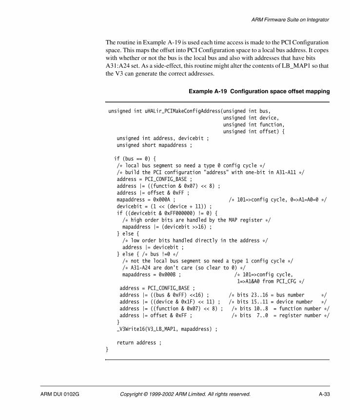
ARM Firmware Suite on Integrator
The routine in Example A-19 is used each time access is made to the PCI Configuration space. This maps the offset into PCI Configuration space to a local bus address. It copes with whether or not the bus is the local bus and also with addresses that have bits A31:A24 set. As a side-effect, this routine might alter the contents of LB_MAP1 so that the V3 can generate the correct addresses.
Example A-19 Configuration space offset mapping
unsigned int uHALir_PCIMakeConfigAddress(unsigned int bus, unsigned int device, unsigned int function, unsigned int offset) { unsigned int address, devicebit ; unsigned short mapaddress ;
if (bus == 0) { /* local bus segment so need a type 0 config cycle */ /* build the PCI configuration "address" with one-bit in A31-A11 */ address = PCI_CONFIG_BASE ; address |= ((function & 0x07) << 8) ; address |= offset & 0xFF ; mapaddress = 0x000A ; /* 101=>config cycle, 0=>A1=A0=0 */ devicebit = (1 << (device + 11)) ; if ((devicebit & 0xFF000000) != 0) { /* high order bits are handled by the MAP register */ mapaddress |= (devicebit >>16) ; } else { /* low order bits handled directly in the address */ address |= devicebit ; } else { /* bus !=0 */ /* not the local bus segment so need a type 1 config cycle */ /* A31-A24 are don't care (so clear to 0) */ mapaddress = 0x000B ; /* 101=>config cycle, 1=>A1&A0 from PCI_CFG */ address = PCI_CONFIG_BASE ; address |= ((bus & 0xFF) <<16) ; /* bits 23..16 = bus number */ address |= ((device & 0x1F) << 11) ; /* bits 15..11 = device number */ address |= ((function & 0x07) << 8) ; /* bits 10..8 = function number */ address |= offset & 0xFF ; /* bits 7..0 = register number */ } _V3Write16(V3_LB_MAP1, mapaddress) ;
return address ;}
ARM DUI 0102G Copyright © 1999-2002 ARM Limited. All rights reserved. A-33

ARM Firmware Suite on Integrator
Example A-20 shows a typical usage of the configuration routines. In this example, a byte is read from PCI Configuration space:
Example A-20 Reading a byte from PCI configuration space
unsigned char uHALr_PCICfgRead8(unsigned int bus, unsigned int device,\\ unsigned int function, unsigned int offset) {pointer unsigned char pAddress ;unsigned char data ; // open the (closed) configuration window from local bus memory _V3OpenConfigWindow() ;
/* generate the address of correct configuration space */ pAddress = (pointer unsigned char)(uHALir_PCIMakeConfigAddress(bus, \\ device, function, offset)) ;
/* now that we have valid params, go read the config space data */ data = *pAddress ;
// close the window _V3CloseConfigWindow() ;
return(data) ;}
A-34 Copyright © 1999-2002 ARM Limited. All rights reserved. ARM DUI 0102G

ARM Firmware Suite on Integrator
A.5.4 Interrupt routing
The Integrator-specific interrupt routing code uses a static routing table, as shown in Example A-21. This provides the generic PCI code with mapping of the interrupt numbers, the slot a device occupies, and the interrupt pin it uses.
Example A-21 Interrupt mapping
unsigned char uHALir_PCIMapInterrupt(unsigned char pin, unsigned char slot) { #define INTA IRQ_PCIINT0 #define INTB IRQ_PCIINT1 #define INTC IRQ_PCIINT2 #define INTD IRQ_PCIINT3
//DANGER! For now this is the SDM interrupt table... char irq_tab[12][4] = { // INTA INTB INTC INTD { INTA, INTB, INTC, INTD }, // idsel 20, slot 9 { INTB, INTC, INTD, INTA }, // idsel 21, slot 10 { INTC, INTD, INTA, INTB }, // idsel 22, slot 11 { INTD, INTA, INTB, INTC }, // idsel 23, slot 12 { INTA, INTB, INTC, INTD }, // idsel 24, slot 13 { INTB, INTC, INTD, INTA }, // idsel 25, slot 14 { INTC, INTD, INTA, INTB }, // idsel 26, slot 15 { INTD, INTA, INTB, INTC }, // idsel 27, slot 16 { INTA, INTB, INTC, INTD }, // idsel 28, slot 17 { INTB, INTC, INTD, INTA }, // idsel 29, slot 18 { INTC, INTD, INTA, INTB }, // idsel 30, slot 19 { INTD, INTA, INTB, INTC } // idsel 31, slot 20} ;uHALr_printf("pin = %d, slot = %d\n", pin, slot) ;
if (pin == 0) pin = 1 ; //if PIN = 0, default to A return irq_tab[slot-9][pin-1] ; //return the magic number}
ARM DUI 0102G Copyright © 1999-2002 ARM Limited. All rights reserved. A-35

ARM Firmware Suite on Integrator
A-36 Copyright © 1999-2002 ARM Limited. All rights reserved. ARM DUI 0102G

Appendix B ARM Firmware Suite on Prospector
This appendix provides implementation-specific details about using the AFS on the Prospector development system. All components of the AFS are supported. It contains the following sections:
• About Prospector on page B-2
• Prospector-specific commands for boot monitor on page B-3
• Using boot monitor on Prospector on page B-6
• Angel on Prospector on page B-10.
ARM DUI 0102G Copyright © 1999-2002 ARM Limited. All rights reserved. B-1
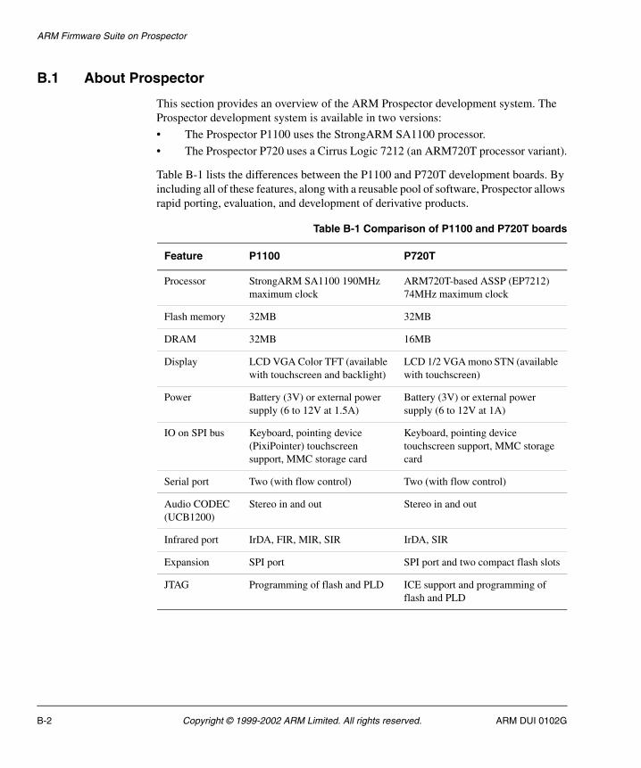
ARM Firmware Suite on Prospector
B.1 About Prospector
This section provides an overview of the ARM Prospector development system. The Prospector development system is available in two versions:
• The Prospector P1100 uses the StrongARM SA1100 processor.
• The Prospector P720 uses a Cirrus Logic 7212 (an ARM720T processor variant).
Table B-1 lists the differences between the P1100 and P720T development boards. By including all of these features, along with a reusable pool of software, Prospector allows rapid porting, evaluation, and development of derivative products.
Table B-1 Comparison of P1100 and P720T boards
Feature P1100 P720T
Processor StrongARM SA1100 190MHz maximum clock
ARM720T-based ASSP (EP7212) 74MHz maximum clock
Flash memory 32MB 32MB
DRAM 32MB 16MB
Display LCD VGA Color TFT (available with touchscreen and backlight)
LCD 1/2 VGA mono STN (available with touchscreen)
Power Battery (3V) or external power supply (6 to 12V at 1.5A)
Battery (3V) or external power supply (6 to 12V at 1A)
IO on SPI bus Keyboard, pointing device (PixiPointer) touchscreen support, MMC storage card
Keyboard, pointing device touchscreen support, MMC storage card
Serial port Two (with flow control) Two (with flow control)
Audio CODEC (UCB1200)
Stereo in and out Stereo in and out
Infrared port IrDA, FIR, MIR, SIR IrDA, SIR
Expansion SPI port SPI port and two compact flash slots
JTAG Programming of flash and PLD ICE support and programming of flash and PLD
B-2 Copyright © 1999-2002 ARM Limited. All rights reserved. ARM DUI 0102G

ARM Firmware Suite on Prospector
B.2 Prospector-specific commands for boot monitor
The Prospector platforms provide a set of system-specific boot monitor commands. These are listed in Table B-2. Commands are not case-sensitive.
B.2.1 D, Display memory at address
This command displays memory at hex address as shown in Example B-1.
Example B-1 Display memory
[Prospector P-1100] boot Monitor > d 0x01000000Displaying memory at 0x10000000x01000000: C80000000x01000004: 001800C10x01000008: 001801010x0100000C: 002000000x01000010: 008100C00x01000014: 2C0305000x01000018: 00882A900x0100001C: 00040D78
B.2.2 G, Go to address
This command transfers control to the hex address supplied.
Table B-2 Prospector system-specific commands
Command Action
D address Display memory at address (use hex format)
G address Go to address (use hex format)
H or ? Display help
P address data Poke data at address (use hex format for both values)
R number Run image number from flash
V View images in flash (boot and application flash)
X command Exit board-specific command mode
ARM DUI 0102G Copyright © 1999-2002 ARM Limited. All rights reserved. B-3
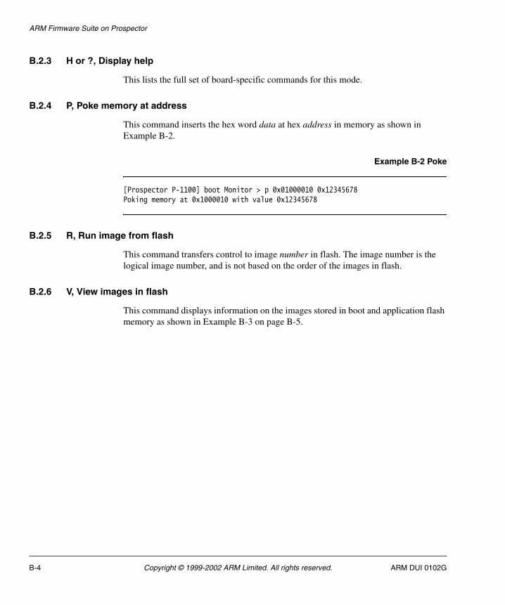
ARM Firmware Suite on Prospector
B.2.3 H or ?, Display help
This lists the full set of board-specific commands for this mode.
B.2.4 P, Poke memory at address
This command inserts the hex word data at hex address in memory as shown in Example B-2.
Example B-2 Poke
[Prospector P-1100] boot Monitor > p 0x01000010 0x12345678Poking memory at 0x1000010 with value 0x12345678
B.2.5 R, Run image from flash
This command transfers control to image number in flash. The image number is the logical image number, and is not based on the order of the images in flash.
B.2.6 V, View images in flash
This command displays information on the images stored in boot and application flash memory as shown in Example B-3 on page B-5.
B-4 Copyright © 1999-2002 ARM Limited. All rights reserved. ARM DUI 0102G

ARM Firmware Suite on Prospector
Example B-3 View output
[Prospector P-1100] boot Monitor > v
There are 2 256KByte blocks of Boot Flash:Images found============Block Size ImageNo Name Compress----- ---- ------- ---- -------- 0 1 4,280,910 bootPROM (0x04000000-0x0403FFEC) 1 1 911 Angel (0x04040000-0x0407FFEC)
There are 126 256KByte blocks of Application Flash:Images found============Block Size ImageNo Name Compress----- ---- ------- ---- -------- 0 1 1 Bubble (0x04080000-0x040BFFEC) 62 5 62 Pics (0x05000000-0x0513FFEC) 110 4 110 TopCat (0x05C00000-0x05CFFFEC) 114 5 120 slideshow Y (0x05D00000-0x05EFFFEC)
System Information Blocks=========================Block Owner Index Size----- ----- ----- ---- 125 ARM Boot Monitor 0 260 (0x5FC0000)
B.2.7 X, Exit board-specific command mode
Enter a single X to exit the board-specific command mode. Enter X followed by a command to execute a single command and then return to board-specific mode.
ARM DUI 0102G Copyright © 1999-2002 ARM Limited. All rights reserved. B-5
ARM Firmware Suite on Prospector
B.3 Using boot monitor on Prospector
This section describes the power-on sequence for the Prospector boards. The boot switcher is embedded in the boot monitor and is the first thing that is run. It reads switch U25-5 and, if it is on, passes control to the default application (boot monitor). If it is off, the boot switcher attempts to find and run an image in flash. See Flash on Prospector for a description of flash memory on Prospector systems.
B.3.1 Connecting to boot monitor
The boot monitor uses the serial port connected to COM1. The settings are 38,400 bps, 8 data bits, and 1 stop bit.
B.3.2 Flash on Prospector
Prospector flash memory is logically divided into two areas:
• Application flash.
• Boot flash.
Application flash
The application flash is a general-purpose area that you can use to store any images or data that require to be held in nonvolatile memory. The Flash Library implements a simple mechanism for storing multiple images in flash. This structure enables the boot switcher to select and run the correct boot image. The ARM Flash Utility uses the Flash Library to program and delete images in application flash. The Flash Library supports storing an image in either a single block or multiple blocks (although they must be contiguous).
Boot flash
The boot flash contains the boot monitor and switcher. This device can be reprogrammed using BootFU.
B.3.3 Image formats
AFS uses the following image formats:
.axf ELF
.bin Plain binary file
.m32 Motorola 32 S Record
.i32 Intel Hex.
B-6 Copyright © 1999-2002 ARM Limited. All rights reserved. ARM DUI 0102G
ARM Firmware Suite on Prospector
For Prospector, the µHAL demos CodeWarrior project files always build .axf format images. However, the makefile also builds .axf and .bin format images. This is because the makefile is generic across all platforms and the .bin format image is required for other platforms. Images for both the P1100 and the P720T are found in the Build subdirectories of the uHALDemos directory.
The images for the Prospector P1100 are in AFSv1_4\Images\Prospector1100.
The images for the Prospector P720T are in AFSv1_4\Images\Prospector720T.
Location of images in flash
The standalone variants of the µHAL demo program are built to run from block 0 of application flash (0x4080000). You can change this by changing the read-only base address when linking the image. If the read-only base is an address in RAM the boot switcher copies the image into RAM before transferring control to it. Semihosted programs always run from DRAM at 0x8000.
B.3.4 Start-up sequence
The boot switcher allows you to program multiple executable images into flash and provides a simple mechanism to run them. When power is applied to Prospector, the following steps occur:
1. The boot switcher code is executed. This code looks at switch U25-5 to determine whether the default application (boot monitor) or a user-selected image must be run.
2. If the user-selected image must be run, the boot switcher looks for a SIB which contains the image number. Then flash is scanned for a matching image number and the image checksum is calculated and validated.
3. If the image footer indicates that it must run from RAM, then memory is initialized before the image is copied into place.
4. Control is passed to the selected image.
If the image cannot be found, or the checksum fails, control is passed back to the boot monitor, which sends an appropriate message out of the serial port before printing the banner. If the boot switcher is unable to find or run an image in flash, the red LED on the motherboard is illuminated.
ARM DUI 0102G Copyright © 1999-2002 ARM Limited. All rights reserved. B-7

ARM Firmware Suite on Prospector
B.3.5 Prospector system-specific boot monitor
The Prospector boot monitor is programmed into the boot flash as image 4280910 (0x41524E or ’ARM’+1). This allows the boot switcher code to copy the image to RAM before executing it.
The boot monitor has to run from RAM in order to program data into flash, as the flash does not allow read access when programming. The top 32KB of RAM is reserved for the MMU Lookup Tables.
The Prospector provides a set of system-specific boot monitor commands. See Prospector-specific commands for boot monitor on page B-3.
B.3.6 Loading images using boot monitor
Use a terminal emulator that is able to send raw ASCII data files to load Motorola 32 S-record images. In the ARM Firmware Suite, Motorola 32 S-record images are built with the .m32 file extension. Motorola 32 S-record files can be built for images such as, for example, the standalone µHAL demo programs, using the FromELF utility.
Use the Motorola 32 S-record loader as follows:
1. Set your terminal emulator to enable XON/XOFF flow control.
2. Reset the Prospector system with switch U25-5 in the ON position. This causes the boot monitor command interpreter to run.
3. At the command prompt type L to start the Motorola 32 S-record loader. The following text is displayed:
boot Monitor > lLoad Motorola S Records into flashDeleting Image 0Type Ctrl/C to exit loader.
Any image the boot monitor loads is numbered image 0. If an image 0 already exists it is deleted first. See L, Load S-records into flash on page 3-7 for more information on the load command.
4. Use the send text file option to download the Motorola 32 S-record image.
The boot monitor transmits a dot for every 64 records received from the terminal emulator.
B-8 Copyright © 1999-2002 ARM Limited. All rights reserved. ARM DUI 0102G

ARM Firmware Suite on Prospector
5. When the terminal emulator has finished sending the file, type Ctrl+C to exit the loader. On exit the loader displays the number of records loaded and the time the load took. It also lists any blocks it has overwritten.
6. Move switch U25-5 to the OFF position and reset the system to run the image.
7. After the boot monitor has loaded the image, it sets the boot image number to zero. When the system restarts, the boot switcher finds and boots the last image loaded.
ARM DUI 0102G Copyright © 1999-2002 ARM Limited. All rights reserved. B-9
ARM Firmware Suite on Prospector
B.4 Angel on Prospector
This section provides an overview of Angel on the Prospector development systems.
B.4.1 Image format
The Angel build for Prospector builds .axf and .bin format images.
The images for the Prospector P1100 are in AFSv1_4\Images\Prospector1100.
The images for the Prospector P720T are in AFSv1_4\Images\Prospector720T.
B.4.2 Location in memory
Angel is linked to run from DRAM. For the P1100, the actual address it is linked at is 0x01FE8000 which is near the top of the 32MB DRAM region.
For the P720T, the actual address it is linked at is 0x00FE8000 which is near the top of the 16MB DRAM region.
The top 32KB of DRAM is reserved for the MMU lookup tables and the boot monitor. The Angel executable occupies the memory below them.
B.4.3 Caches
Angel for Prospector runs with caches and MMU enabled. This allows applications to get the maximum performance from the system. Use the µHAL functions to control the cache. See Simple API MMU and cache functions on page 2-11 and Extended API MMU and cache functions on page 2-39.
B.4.4 Line speed
The maximum line speed that Angel supports depends on factors such as the clock settings for the processor, and on whether caches are enabled. Running on a 190MHz system with caches enabled, a maximum line speed of 115,200bps is supported.
B-10 Copyright © 1999-2002 ARM Limited. All rights reserved. ARM DUI 0102G

Appendix C ARM Firmware Suite on the Intel IQ80310 and IQ80321
This appendix provides implementation-specific details about using the AFS on the following development systems:
• Intel IQ80310 Software Development and Processor Evaluation Kit (IQ80310)
• Intel IQ80321 Evaluation Platform and Customer Reference Board(IQ80321).
These are referred to collectively in this appendix as the Intel IQ systems. All components of the AFS are supported.
This appendix contains the following sections:
• About the IQ80310 development kit on page C-2
• IQ-specific commands for boot monitor on page C-4
• Using boot monitor on the Intel IQ systems on page C-7
• Angel on the Intel IQ systems on page C-10.
ARM DUI 0102G Copyright © 1999-2002 ARM Limited. All rights reserved. C-1

ARM Firmware Suite on the Intel IQ80310 and IQ80321
C.1 About the IQ80310 development kit
This section provides an overview of the IQ80310 development kit. The IQ80310 is a PCI plug-in card with extra connectors to allow access to the secondary PCI bus.
The Intel IOP310 I/O chip-set includes
• The Intel 80200 microprocessor, featuring a 600 MHz Intel XScale core. The XScale core is compliant with ARM v5TE architecture and includes 32Kbytes of instruction and 32Kbytes of data cache.
• The Intel 80312 I/O companion chip with an integrated PCI-to-PCI bridge, 100 MHz SDRAM interface, and I2O support.
C.1.1 AFS support
The ARM Firmware Suite on the IQ80310 supports system initialization, ECC memory, MMU and cache setup. The LEDs, serial ports and PCI sub-systems are also supported.
AFS arranges the IQ80310 memory map in the same manner as other board ports:
RAM Starts at address 0.
Flash Starts at 64Mb (address 0x04000000).
Other Mapped to the same virtual address as their physical locations.
Because there are no discrete LEDs on the IQ80310, AFS uses the numeric LED horizontal elements as six LEDs. AFS also supports writing hexadecimal values to the numeric LEDs.
Contact your vendor for support on this platform.
C-2 Copyright © 1999-2002 ARM Limited. All rights reserved. ARM DUI 0102G

ARM Firmware Suite on the Intel IQ80310 and IQ80321
C.2 About the IQ80321 development kit
This section provides an overview of the IQ80321 development kit. The IQ80321 is a PCI plug-in card with extra connectors to allow access to the secondary PCI bus.
The Intel IQ80321 board includes
• The Intel 80321 Verde IO microprocessor, featuring a 600 MHz Intel XScale core. The XScale core is compliant with ARM v5TE architecture and includes 32Kbytes of instruction and 32Kbytes of data cache.
• Intel 82544 Giga Ethernet controller.
• TI TL16C550C UART.
• 16MB of flash memory (28F640J3A).
• 32KB of instruction cache and 32KB of data cache.
• PCI bus application bridge.
• Socket for PC200 DDR memory.
C.2.1 AFS support
The ARM Firmware Suite on the IQ80321 supports system initialization, ECC memory, MMU and cache setup. The LEDs, serial ports and PCI sub-systems are also supported.
AFS arranges the IQ80321 memory map in the same manner as other board ports:
RAM Starts at address 0.
Flash Starts at 128Mb (address 0x08000000) and is 8Mb in size .
Other Mapped to the same virtual address as their physical locations.
Because there are no discrete LEDs on the IQ80321, AFS uses the two numeric LED horizontal elements as individual LEDs. AFS also supports writing hexadecimal values to the numeric LEDs.
ARM DUI 0102G Copyright © 1999-2002 ARM Limited. All rights reserved. C-3

ARM Firmware Suite on the Intel IQ80310 and IQ80321
C.3 IQ-specific commands for boot monitor
The Intel IQ systems provide a set of system-specific boot monitor commands. These are listed in Table C-1. Examples are provided in H or ?, Display help on page C-5 to X, Exit board-specific command mode on page C-6.
C.3.1 D, Display memory at address
This command displays memory at hex address as shown in Example C-1.
Example C-1 Display memory
[Coyanosa] boot Monitor > d 0x01000000Displaying memory at 0x10000000x01000000: C80000000x01000004: 001800C10x01000008: 001801010x0100000C: 002000000x01000010: 008100C00x01000014: 2C0305000x01000018: 00882A900x0100001C: 00040D78
C.3.2 G, Go to address
This command transfers control to the hex address supplied.
Table C-1 IQ80310 system-specific commands
Command Action
D address Display memory at address (use hex format)
G address Go to address (use hex format)
H or ? Display help
P address data Poke data at address (use hex format for both values)
R number Run image number from flash
V View images in flash (boot and application flash)
X command Exit board-specific command mode
C-4 Copyright © 1999-2002 ARM Limited. All rights reserved. ARM DUI 0102G
ARM Firmware Suite on the Intel IQ80310 and IQ80321
C.3.3 H or ?, Display help
This lists the full set of board-specific commands for this mode.
C.3.4 P, Poke memory at address
This command inserts the hex word data at hex address in memory as shown in Example C-2.
Example C-2 Poke
[Coyanosa] boot Monitor > p 0x01000010 0x12345678Poking memory at 0x1000010 with value 0x12345678
C.3.5 R, Run image from flash
This command transfers control to image number in flash. The image number is the logical image number, and is not based on the order of the images in flash.
C.3.6 V, View images in flash
This command displays information on the images stored in boot and application flash memory as shown in Example C-3 on page C-6.
ARM DUI 0102G Copyright © 1999-2002 ARM Limited. All rights reserved. C-5

ARM Firmware Suite on the Intel IQ80310 and IQ80321
Example C-3 View output
[Coyanosa] boot Monitor > v
There are 4 128KByte blocks of Boot Flash:Images found============Block Size ImageNo Name Compress----- ---- ------- ---- -------- 0 1 4,280,910 bootMonitor (0x04000000-0x0401FFEC) 1 1 911 Angel (0x04020000-0x0403FFEC) 2 2 411 RedBoot (0x04040000-0x0407FFEC)
There are 60 128KByte blocks of Application Flash:Images found============Block Size ImageNo Name Compress----- ---- ------- ---- -------- 0 1 1 Bubble (0x04080000-0x040BFFEC) 62 5 62 Pics (0x05000000-0x0513FFEC) 110 4 110 TopCat (0x05C00000-0x05CFFFEC) 114 5 120 slideshow Y (0x05D00000-0x05EFFFEC)
System Information Blocks=========================Address Owner Size Idx Rev----- ----- ----- --- ---0x47e0000 ARM Boot Monitor 312 0 0
C.3.7 X, Exit board-specific command mode
Enter a single X to exit the board-specific command mode. Enter X followed by a command to execute a single command and then return to board-specific mode.
C-6 Copyright © 1999-2002 ARM Limited. All rights reserved. ARM DUI 0102G

ARM Firmware Suite on the Intel IQ80310 and IQ80321
C.4 Using boot monitor on the Intel IQ systems
This section describes the power-on sequence for the boards.
C.4.1 Connecting to boot monitor
The boot monitor uses the serial port (J9 on the IQ80310) . The settings are 115,200bps, 8 data bits, and 1 stop bit.
C.4.2 Flash memory
Flash memory is logically divided into two areas:
• application flash
• boot flash.
µHAL maps the flash from physical address 0 to virtual address:
• 64Mbytes (0x04000000) for the IQ80310
• 128Mbytes (0x08000000) for the IQ80321.
This area is set as cacheable in order to maximize performance of applications running directly from flash. A second virtual area is defined, just above this, as non-cacheable. This area is used only for programming flash.
Application flash
The application flash is a general-purpose area that can be used to store any images or data that require to be held in nonvolatile memory. The Flash Library implements a simple mechanism for storing multiple images in flash. This structure enables the boot switcher to select and run the correct boot image. The ARM Flash Utility (AFU) uses the Flash Library to program and delete images in application flash. The Flash Library supports storing an image in either a single block or multiple blocks (although they must be contiguous).
Boot flash
The boot flash contains the boot monitor and switcher, the Angel Debug Monitor and Redboot. This device can be reprogrammed using BootFU.
Redboot is an acronym for “Red Hat Embedded Debug and Bootstrap” and is the standard embedded system debug/bootstrap environment from Red Hat. It replaces the previous Red Hat debug/boot tools.
ARM DUI 0102G Copyright © 1999-2002 ARM Limited. All rights reserved. C-7

ARM Firmware Suite on the Intel IQ80310 and IQ80321
C.4.3 Boot switcher
The boot switcher is embedded in the boot monitor and is the first thing that is run. Action taken depends on the setting of switch S1:
0 or 1 Control passes to Redboot.
2 Control passes to the default ARM application (boot monitor).
Other The boot switcher attempts to find and run an image in flash.
C.4.4 Start-up sequence
The boot switcher allows the user to program multiple executable images into flash and provides a simple mechanism to run them. When power is applied to the board, the following steps occur:
1. The boot switcher code is executed. This code looks at switch S1 (the rotary switch) to determine whether Redboot, the default ARM application (boot monitor), or a user-selected image must be run.
2. If the user-selected image must be run, the boot switcher looks for a SIB which contains the image number. Then flash is scanned for a matching image number and the image checksum is calculated and validated.
3. If the image footer indicates that it must run from RAM, then memory is initialized before the image is copied into place.
4. Control is passed to the selected image.
If the image cannot be found, or the checksum fails, control is passed back to the boot monitor, which sends an appropriate message out of the serial port before printing the banner. If the boot switcher is unable to find or run an image in flash, the numeric LED on the motherboard is illuminated.
C.4.5 System-specific boot monitor
The Intel IQ systems boot monitor is programmed into the boot flash as image 4280910 (that is, 'ARM'+1). This allows the boot switcher code to copy the image to RAM before executing it.
The boot monitor has to run from RAM in order to program data into flash, as the flash does not allow read access when programming. The actual address it is linked at is
• 0x01FD0000 for the IQ80310. This is near the top of the 32MB DRAM region.
• 0x07F80000 for the IQ80321. This is near the top of the 128MB DRAM region.
The top 32KB of RAM is reserved for the MMU Lookup Tables.
C-8 Copyright © 1999-2002 ARM Limited. All rights reserved. ARM DUI 0102G

ARM Firmware Suite on the Intel IQ80310 and IQ80321
C.4.6 Loading images using boot monitor
Use a terminal emulator that is able to send raw ASCII data files to load Motorola 32 S-record images. In the ARM Firmware Suite, Motorola 32 S-record images are built with the .m32 file extension. Motorola 32 S-record files can be built for images such as, for example, the standalone µHAL demo programs, using the FromELF utility.
Use the Motorola 32 S-record loader as follows:
1. Set your terminal emulator to enable XON/XOFF flow control.
2. Reset the Intel IQ system with the rotary switch set to 2. This causes the boot monitor command interpreter to run.
3. At the command prompt type L to start the Motorola 32 S-record loader. The following text is displayed:
boot Monitor > lLoad Motorola S Records into flashDeleting Image 0Type Ctrl/C to exit loader.
Any image the boot monitor loads is numbered image 0. If an image 0 already exists it is deleted first. See L, Load S-records into flash on page 3-7 for more information on the load command.
4. Use the send text file option to download the Motorola 32 S-record image.
The boot monitor transmits a dot for every 64 records received from the terminal emulator.
5. When the terminal emulator has finished sending the file, type Ctrl+C to exit the loader. On exit the loader displays the number of records loaded and the time the load took. It also lists any blocks it has overwritten.
6. Move the rotary switch to 3 and reset the system to run the image.
7. After the boot monitor has loaded the image, it sets the boot image number to zero. When the system restarts, the boot switcher finds and boots the last image loaded.
ARM DUI 0102G Copyright © 1999-2002 ARM Limited. All rights reserved. C-9

ARM Firmware Suite on the Intel IQ80310 and IQ80321
C.5 Angel on the Intel IQ systems
This section provides an overview of Angel on the Intel IQ development systems.
C.5.1 Image format
The Angel builds for the Intel IQ systems build ELF (.axf) and binary (.bin) format images.
The images for the Intel IQ80310 system is in AFSv1_4\Images\Coyanosa.
The images for the Intel IQ80321 system is in AFSv1_4\Images\Worcester.
C.5.2 Location in memory
Angel is linked to run from DRAM. The top of DRAM is reserved for the MMU Lookup Tables and the boot monitor. The Angel executable occupies the memory below that.
The actual address Angel is linked at is:
• 0x01FB8000 for the IQ80310. This is near the top of the 32MB DRAM region.
• 0x07FB8000 for the IQ80321. This is near the top of the 128MB DRAM region.
C.5.3 Caches
Angel for the Intel IQ systems run with caches and MMU enabled. This allows applications to obtain the maximum performance from the system. Use the µHAL functions to control the cache. See Simple API MMU and cache functions on page 2-11 and Extended API MMU and cache functions on page 2-39.
C.5.4 Line speed
When it starts, Angel communicates at 9600bps. On the Intel IQ systems, the maximum line speed of 115,200bps is supported. On the IQ80310 Angel uses J9 for serial communication.
C.5.5 Initial loading of Angel into flash
Angel is pre-loaded into boot-flash block 1 as image 911. The boot switcher relocates the image from flash to RAM. If the Angel image needs to be rebuilt, it can be programmed into any flash block and the boot switcher will execute it when the new image number has been programmed into the SIB.
C-10 Copyright © 1999-2002 ARM Limited. All rights reserved. ARM DUI 0102G
ARM Firmware Suite on the Intel IQ80310 and IQ80321
C.6 Flash recovery
If for any reason the contents of flash becomes corrupt or is deleted use the following procedures to restore it:
• IQ80310 Coyanosa
• IQ80321 Worcester on page C-12.
C.6.1 IQ80310 Coyanosa
To re-initialise the board:
1. Connect Multi-ICE to the board, turn on the power and configure your Multi-ICE server.
2. Start a command prompt window and go to the Images\Coyanosa directory.
3. Start the debugger and connect to the Coyanosa board.
4. Ensure that Hot Debug is disabled.
5. Exit the debugger. (This sets the default connection for the debugger to be to the Coyanosa board.)
6. Start the debugger from a command prompt with the appropriate script file:
a. For ADW, enter adw -script coyanosa_adw.li
Click Yes at the prompt asking if you want to debug using the Multi-ICE DLL.
b. For AXD, enter axd -script coyanosa_axd.li
7. The script performs the following actions:
a. The board is initialized.
b. recovery.bin is loaded and executed.
c. bootFU.axf is loaded and executed.
8. Use the bootFU commands to reload flash images.
9. The debugger exits after bootFU terminates. The system is now restored to its initial state.
ARM DUI 0102G Copyright © 1999-2002 ARM Limited. All rights reserved. C-11
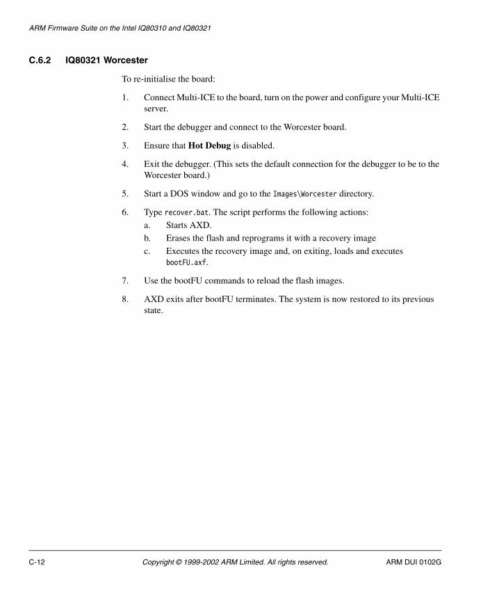
ARM Firmware Suite on the Intel IQ80310 and IQ80321
C.6.2 IQ80321 Worcester
To re-initialise the board:
1. Connect Multi-ICE to the board, turn on the power and configure your Multi-ICE server.
2. Start the debugger and connect to the Worcester board.
3. Ensure that Hot Debug is disabled.
4. Exit the debugger. (This sets the default connection for the debugger to be to the Worcester board.)
5. Start a DOS window and go to the Images\Worcester directory.
6. Type recover.bat. The script performs the following actions:
a. Starts AXD.
b. Erases the flash and reprograms it with a recovery image
c. Executes the recovery image and, on exiting, loads and executes bootFU.axf.
7. Use the bootFU commands to reload the flash images.
8. AXD exits after bootFU terminates. The system is now restored to its previous state.
C-12 Copyright © 1999-2002 ARM Limited. All rights reserved. ARM DUI 0102G

Appendix D ARM Firmware Suite on the ARM Evaluator-7T
This appendix provides implementation-specific details about using the AFS on the ARM Evaluation Board (Evaluator-7T) development system. It contains the following sections:
• About Evaluator-7T on page D-2
• Evaluator-7T-specific commands for boot monitor on page D-3
• Using boot monitor on the Evaluator-7T on page D-6
• Angel on the Evaluator-7T on page D-8
• Manufacturing image on page D-9.
ARM DUI 0102G Copyright © 1999-2002 ARM Limited. All rights reserved. D-1
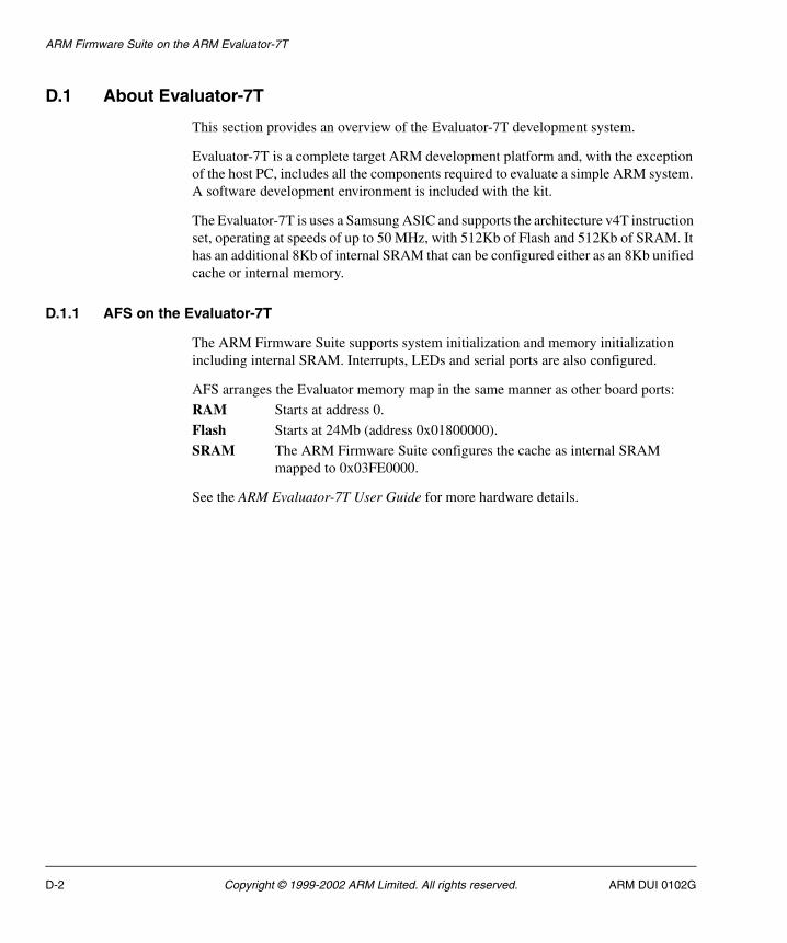
ARM Firmware Suite on the ARM Evaluator-7T
D.1 About Evaluator-7T
This section provides an overview of the Evaluator-7T development system.
Evaluator-7T is a complete target ARM development platform and, with the exception of the host PC, includes all the components required to evaluate a simple ARM system. A software development environment is included with the kit.
The Evaluator-7T is uses a Samsung ASIC and supports the architecture v4T instruction set, operating at speeds of up to 50 MHz, with 512Kb of Flash and 512Kb of SRAM. It has an additional 8Kb of internal SRAM that can be configured either as an 8Kb unified cache or internal memory.
D.1.1 AFS on the Evaluator-7T
The ARM Firmware Suite supports system initialization and memory initialization including internal SRAM. Interrupts, LEDs and serial ports are also configured.
AFS arranges the Evaluator memory map in the same manner as other board ports:
RAM Starts at address 0.
Flash Starts at 24Mb (address 0x01800000).
SRAM The ARM Firmware Suite configures the cache as internal SRAM mapped to 0x03FE0000.
See the ARM Evaluator-7T User Guide for more hardware details.
D-2 Copyright © 1999-2002 ARM Limited. All rights reserved. ARM DUI 0102G

ARM Firmware Suite on the ARM Evaluator-7T
D.2 Evaluator-7T-specific commands for boot monitor
The Evaluator-7T platform provides a set of system-specific boot monitor commands. These are listed in Table D-1. Commands are not case-sensitive.
D.2.1 D, Display memory at address
This command displays memory at hex address as shown in Example D-1.
Example D-1 Display memory
[Evaluator7T] boot Monitor > d 0x01000000Displaying memory at 0x10000000x01000000: C80000000x01000004: 001800C10x01000008: 001801010x0100000C: 002000000x01000010: 008100C00x01000014: 2C0305000x01000018: 00882A900x0100001C: 00040D78
Table D-1 IQ80310 system-specific commands
Command Action
D address Display memory at address (use hex format)
G address Go to address (use hex format)
H or ? Display help
P address data Poke data at address (use hex format for both values)
R number Run image number from flash
V View images in flash (boot and application flash)
X command Exit board-specific command mode
ARM DUI 0102G Copyright © 1999-2002 ARM Limited. All rights reserved. D-3
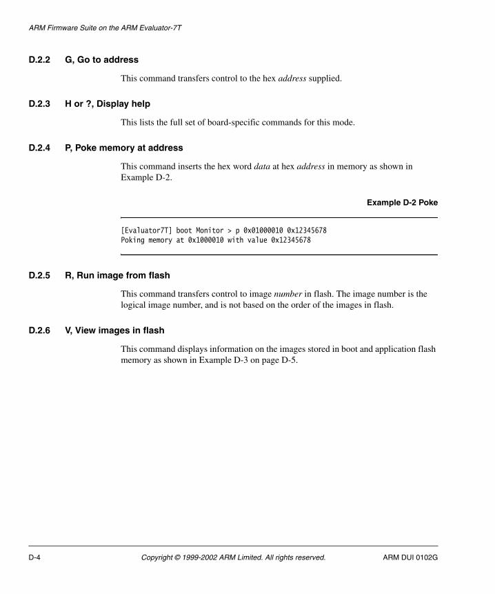
ARM Firmware Suite on the ARM Evaluator-7T
D.2.2 G, Go to address
This command transfers control to the hex address supplied.
D.2.3 H or ?, Display help
This lists the full set of board-specific commands for this mode.
D.2.4 P, Poke memory at address
This command inserts the hex word data at hex address in memory as shown in Example D-2.
Example D-2 Poke
[Evaluator7T] boot Monitor > p 0x01000010 0x12345678Poking memory at 0x1000010 with value 0x12345678
D.2.5 R, Run image from flash
This command transfers control to image number in flash. The image number is the logical image number, and is not based on the order of the images in flash.
D.2.6 V, View images in flash
This command displays information on the images stored in boot and application flash memory as shown in Example D-3 on page D-5.
D-4 Copyright © 1999-2002 ARM Limited. All rights reserved. ARM DUI 0102G

ARM Firmware Suite on the ARM Evaluator-7T
Example D-3 View output
[Evaluator7T] boot Monitor > v
There are 32 4KByte blocks of Boot Flash:Images found============Block Size ImageNo Name Compress----- ---- ------- ---- -------- 0 14 4,280,910 bootMonitor (0x01800000-ox0180DFEC) 1 11 911 angel (0x04020000-0x0403FFEC)
There are 96 4KByte blocks of Application Flash:Images found============Block Size ImageNo Name Compress----- ---- ------- ---- -------- 0 1 1 Bubble (0x01820000-0x01823FEC)
System Information Blocks=========================Address Owner Size Idx Rev----- ----- ----- --- ---0x0187F000 ARM Boot Monitor 312 0 0
D.2.7 X, Exit board-specific command mode
Enter a single X to exit the board-specific command mode. Enter X followed by a command to execute a single command and then return to board-specific mode.
ARM DUI 0102G Copyright © 1999-2002 ARM Limited. All rights reserved. D-5

ARM Firmware Suite on the ARM Evaluator-7T
D.3 Using boot monitor on the Evaluator-7T
This section describes the boot monitor supplied with the Evaluator-7T board.
D.3.1 Connecting to boot monitor
The boot monitor uses the serial port DEBUG COM1. The settings are 38,400bps, 8 data bits, and 1 stop bit.
D.3.2 Flash memory
Evaluator-7T has 512KB of flash memory logically divided into two areas:
• application flash
• boot flash.
µHAL maps the flash from physical address 0 to virtual address 24Mbytes (0x01800000).
Application flash
The application flash is a general-purpose area that can be used to store any images or data that require to be held in nonvolatile memory. The Flash Library implements a simple mechanism for storing multiple images in flash. This structure enables the boot switcher to select and run the correct boot image. AFU uses the Flash Library to program and delete images in application flash. The Flash Library supports storing an image in either a single block or multiple blocks (although they must be contiguous).
Boot flash
The boot flash contains the boot monitor and switcher and the Angel Debug Monitor. This device can be reprogrammed using BootFU.
D.3.3 Boot switcher
The boot switcher routine is embedded in the boot monitor and is the first thing that is run. The action taken depends on the value of DIP switch S4:
1 The default ARM image (boot monitor) runs.
0 The boot switcher attempts to find and run the user selected image in flash.
D-6 Copyright © 1999-2002 ARM Limited. All rights reserved. ARM DUI 0102G
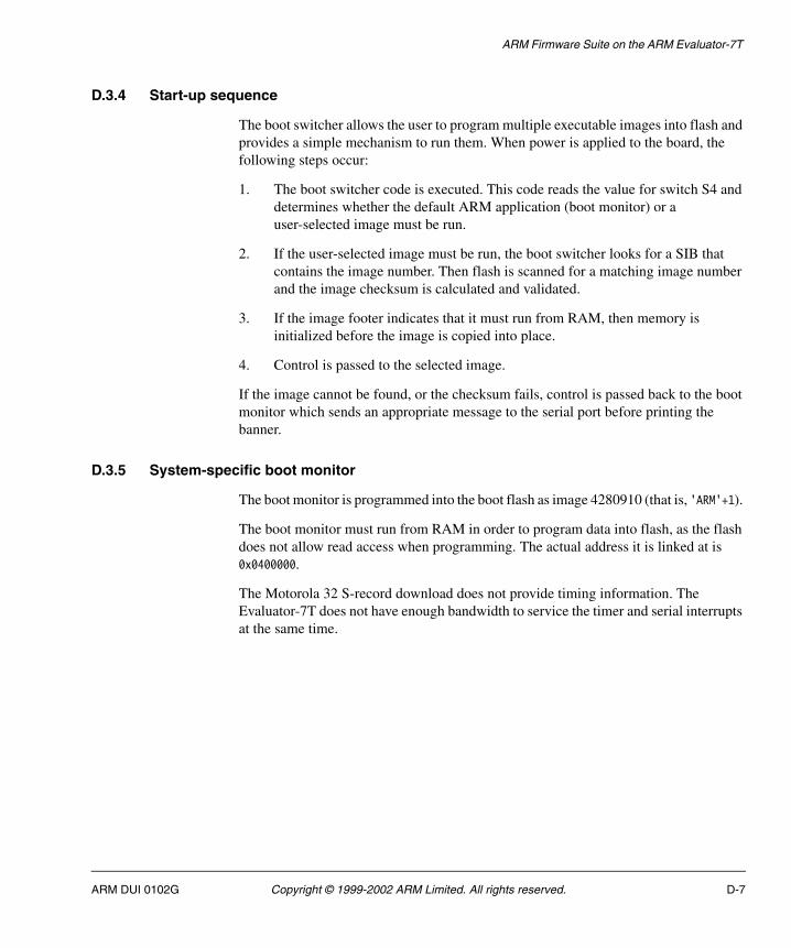
ARM Firmware Suite on the ARM Evaluator-7T
D.3.4 Start-up sequence
The boot switcher allows the user to program multiple executable images into flash and provides a simple mechanism to run them. When power is applied to the board, the following steps occur:
1. The boot switcher code is executed. This code reads the value for switch S4 and determines whether the default ARM application (boot monitor) or a user-selected image must be run.
2. If the user-selected image must be run, the boot switcher looks for a SIB that contains the image number. Then flash is scanned for a matching image number and the image checksum is calculated and validated.
3. If the image footer indicates that it must run from RAM, then memory is initialized before the image is copied into place.
4. Control is passed to the selected image.
If the image cannot be found, or the checksum fails, control is passed back to the boot monitor which sends an appropriate message to the serial port before printing the banner.
D.3.5 System-specific boot monitor
The boot monitor is programmed into the boot flash as image 4280910 (that is, 'ARM'+1).
The boot monitor must run from RAM in order to program data into flash, as the flash does not allow read access when programming. The actual address it is linked at is 0x0400000.
The Motorola 32 S-record download does not provide timing information. The Evaluator-7T does not have enough bandwidth to service the timer and serial interrupts at the same time.
ARM DUI 0102G Copyright © 1999-2002 ARM Limited. All rights reserved. D-7
ARM Firmware Suite on the ARM Evaluator-7T
D.4 Angel on the Evaluator-7T
This section provides an overview of Angel on the Evaluator-7T development system.
D.4.1 Image format
The Angel build for the Evaluator-7T builds .axf and .bin format images.
The images for the board are in AFSv1_4\Images\evaluator7T.
D.4.2 Caches
Angel for Evaluator-7T runs with the SRAM cache disabled.
D.4.3 Location in memory
Angel is linked to run from SRAM. The actual address it is linked at is 0x00074000 which is near the top of the 512kB SRAM region.
D.4.4 Line speed
When it starts, Angel communicates at 9600bps on the DEBUG COM1 serial port. The Evaluator-7T supports a maximum line speed of 38,400bps.
D.4.5 Setting up Angel
The boot switcher relocates the Angel image from flash to RAM.
If the Angel image needs to be re-built, it can be programmed into any flash block. The boot switcher will execute it if the new image number has been programmed into the SIB.
D-8 Copyright © 1999-2002 ARM Limited. All rights reserved. ARM DUI 0102G

ARM Firmware Suite on the ARM Evaluator-7T
D.5 Manufacturing image
A manufacturing image is provided on the CD as \Images\evaluator7t\evaluator7t.bin.
This image can be used to reprogram the entire contents of the Evaluator-7T flash. The image contains bootMonitor, Angel and a SIB with the boot image set to the Angel image (911).
Follow the steps below to program the image into flash:
1. If you are using Multi-ICE, connect Multi-ICE to the board, turn on the power, and configure your Multi-ICE server.
2. Connect to the Evaluator board with either ADW or AXD.
3. Exit the debugger and then restart the debugger. This sets the Evaluator connection as the default connection for the debugger.
4. Start a DOS window and change to the \Images\evaluator7t directory on the CD.
5. Start either ADW or AXD with the appropriate script file
• for ADW, enter adw -script evaluator_adw.li
Click Yes at the prompt asking if you are sure you want to debug using the Multi-ICE DLL.
• for AXD, enter axd -script evaluator_axd.li.
AXD starts with the default connection without prompting you.
6. The debugger will exit after the programming is completed.
The board now has the default bootMonitor and Angel images in flash.
ARM DUI 0102G Copyright © 1999-2002 ARM Limited. All rights reserved. D-9

ARM Firmware Suite on the ARM Evaluator-7T
D-10 Copyright © 1999-2002 ARM Limited. All rights reserved. ARM DUI 0102G

Appendix E ARM Firmware Suite on the Agilent AAED-2000
This appendix provides implementation-specific details about using the AFS on the Agilent AAED-2000 development system. All components of the AFS are supported. It contains the following sections:
• About AAED-2000 on page E-2
• AAED-2000-specific commands for boot monitor on page E-3
• Using boot monitor on AAED-2000 on page E-6
• Angel on the AAED-2000 on page E-9.
ARM DUI 0102G Copyright © 1999-2002 ARM Limited. All rights reserved. E-1
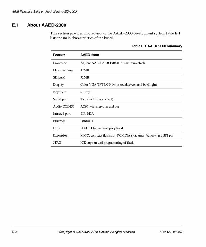
ARM Firmware Suite on the Agilent AAED-2000
E.1 About AAED-2000
This section provides an overview of the AAED-2000 development system.Table E-1 lists the main characteristics of the board.
Table E-1 AAED-2000 summary
Feature AAED-2000
Processor Agilent AAEC-2000 190MHz maximum clock
Flash memory 32MB
SDRAM 32MB
Display Color VGA TFT LCD (with touchscreen and backlight)
Keyboard 61-key
Serial port Two (with flow control)
Audio CODEC AC97 with stereo in and out
Infrared port SIR IrDA
Ethernet 10Base-T
USB USB 1.1 high-speed peripheral
Expansion MMC, compact flash slot, PCMCIA slot, smart battery, and SPI port
JTAG ICE support and programming of flash
E-2 Copyright © 1999-2002 ARM Limited. All rights reserved. ARM DUI 0102G

ARM Firmware Suite on the Agilent AAED-2000
E.2 AAED-2000-specific commands for boot monitor
The AAED-2000 boards provide a set of system-specific boot monitor commands. These are listed in Table E-2. Commands are not case-sensitive.
E.2.1 D, Display memory at address
This command displays memory at hex address as shown in Example E-1.
Example E-1 Display memory
[AAED-2000] boot Monitor > d 0x01000000Displaying memory at 0x10000000x01000000: C80000000x01000004: 001800C10x01000008: 001801010x0100000C: 002000000x01000010: 008100C00x01000014: 2C0305000x01000018: 00882A900x0100001C: 00040D78
Table E-2 AAED-2000 system-specific commands
Command Action
D address Display memory at address (use hex format)
G address Go to address (use hex format)
H or ? Display help
P address data Poke data at address (use hex format for both values)
R number Run image number from flash
V View images in flash (boot and application flash)
X command Exit board-specific command mode
ARM DUI 0102G Copyright © 1999-2002 ARM Limited. All rights reserved. E-3

ARM Firmware Suite on the Agilent AAED-2000
E.2.2 G, Go to address
This command transfers control to the hex address supplied.
E.2.3 H or ?, Display help
This lists the full set of board-specific commands for this mode.
E.2.4 P, Poke memory at address
This command inserts the hex word data at hex address in memory as shown in Example E-2.
Example E-2 Poke
[AAED-2000] boot Monitor > p 0x01000010 0x12345678Poking memory at 0x1000010 with value 0x12345678
E.2.5 R, Run image from flash
This command transfers control to image number in flash. The image number is the logical image number, and is not based on the order of the images in flash.
E.2.6 V, View images in flash
This command displays information on the images stored in boot and application flash memory as shown in Example E-3 on page E-5.
E-4 Copyright © 1999-2002 ARM Limited. All rights reserved. ARM DUI 0102G

ARM Firmware Suite on the Agilent AAED-2000
Example E-3 View output
[AAED-2000] boot Monitor > v
There are 2 256KByte blocks of Boot Flash:Images found============Block Size ImageNo Name Compress----- ---- ------- ---- -------- 0 1 4,280,910 bootPROM (0x04000000-0x0403FFEC) 1 1 911 Angel (0x04040000-0x0407FFEC)
There are 126 256KByte blocks of Application Flash:Images found============Block Size ImageNo Name Compress----- ---- ------- ---- -------- 0 1 1 Bubble (0x04080000-0x040BFFEC) 62 5 62 Pics (0x05000000-0x0513FFEC) 110 4 110 TopCat (0x05C00000-0x05CFFFEC) 114 5 120 slideshow Y (0x05D00000-0x05EFFFEC)
System Information Blocks========================= Block Owner Index Size----- ----- ----- ---- 125 ARM Boot Monitor 0 260 (0x5FC0000)
E.2.7 X, Exit board-specific command mode
Enter a single X to exit the board-specific command mode. Enter X followed by a command to execute a single command and then return to board-specific mode.
ARM DUI 0102G Copyright © 1999-2002 ARM Limited. All rights reserved. E-5

ARM Firmware Suite on the Agilent AAED-2000
E.3 Using boot monitor on AAED-2000
This section describes the power-on sequence for the AAED-2000 board. The boot switcher is embedded in the boot monitor and is the first thing that is run. If there is a bootable image in flash, the boot switcher attempts to run that image, otherwise it passes control to the default application (boot monitor). See Flash on AAED-2000 for a description of flash memory on AAED-2000 systems.
E.3.1 Connecting to boot monitor
The boot monitor uses the serial port COM-A. The settings are 38,400bps, 8 data bits, and 1 stop bit.
E.3.2 Flash on AAED-2000
AAED-2000 flash memory is logically divided into two areas:
• application flash
• boot flash.
Application flash
The application flash is a general-purpose area that you can use to store any images or data that require to be held in nonvolatile memory. The Flash Library implements a simple mechanism for storing multiple images in flash. This structure enables the boot switcher to select and run the correct boot image. The ARM Flash Utility uses the Flash Library to program and delete images in application flash. The Flash Library supports storing an image in either a single block or multiple blocks (although they must be contiguous).
Boot flash
The boot flash contains the boot monitor and switcher. This device can be reprogrammed using BootFU.
E.3.3 Image formats
AFS uses the following image formats:
.axf ELF
.bin Plain binary file
.m32 Motorola 32 S Record
.i32 Intel Hex.
E-6 Copyright © 1999-2002 ARM Limited. All rights reserved. ARM DUI 0102G

ARM Firmware Suite on the Agilent AAED-2000
For the AAED-2000, the µHAL demos CodeWarrior project files always build .axf format images. However, the makefile also builds .axf and .bin format images. This is because the makefile is generic across all platforms and the .bin format images are required for other platforms. Images for the AAED-2000 are in the AFSv1_4\Demos\P920T directory.
Location of images in flash
The standalone variants of the µHAL demo program are built to run from block 0 of application flash. You can change this by changing the read-only base address when linking the image. If the read-only base is an address in RAM the boot switcher copies the image into RAM before transferring control to it. Semihosted programs always run from SDRAM.
E.3.4 Start-up sequence
The boot switcher allows you to program multiple executable images into flash and provides a simple mechanism to run them. When power is applied to AAED-2000, the following steps occur:
1. The boot switcher code is executed. The code checks if a key is pressed to determine whether the default ARM application (boot monitor) or a user-selected image must be run.
2. If the user-selected image must be run, the boot switcher looks for a SIB which contains the image number. Then flash is scanned for a matching image number and the image checksum is calculated and validated.
3. If the image footer indicates that it must run from RAM, then memory is initialized before the image is copied into place.
4. Control is passed to the selected image.
If the image cannot be found, or the checksum fails, control is passed back to the boot monitor, which sends an appropriate message out of the serial port before printing the banner.
E.3.5 AAED-2000 system-specific boot monitor
The AAED-2000 boot monitor is programmed into the boot flash as image 4280910 (0x41524E or ’ARM’+1). This allows the boot switcher code to copy the image to RAM before executing it.
ARM DUI 0102G Copyright © 1999-2002 ARM Limited. All rights reserved. E-7

ARM Firmware Suite on the Agilent AAED-2000
The boot monitor has to run from RAM in order to program data into flash, as the flash does not allow read access when programming. The top 1MB of RAM is reserved for the MMU Lookup Tables.
The AAED-2000 provides a set of system-specific boot monitor commands. See AAED-2000-specific commands for boot monitor on page E-3.
E.3.6 Loading images
Use a terminal emulator that is able to send raw ASCII data files to load Motorola 32 S-record images. In the ARM Firmware Suite, Motorola 32 S-record images are built with the .m32 file extension. Motorola 32 S-record files can be built for images such as, for example, the standalone µHAL demo programs, using the FromELF utility.
Use the Motorola 32 S-record loader as follows:
1. Set your terminal emulator to enable XON/XOFF flow control.
2. Reset the AAED-2000 system with switch U25-5 in the ON position. This causes the boot monitor command interpreter to run.
3. At the command prompt type L to start the Motorola 32 S-record loader. The following text is displayed:
boot Monitor > lLoad Motorola S Records into flashDeleting Image 0Type Ctrl/C to exit loader.
Any image the boot monitor loads is numbered image 0. If an image 0 already exists it is deleted first. See L, Load S-records into flash on page 3-7 for more information on the load command.
4. Use the send text file option to download the Motorola 32 S-record image.
The boot monitor transmits a dot for every 64 records received from the terminal emulator.
5. When the terminal emulator has finished sending the file, type Ctrl+C to exit the loader. On exit the loader displays the number of records loaded and the time the load took. It also lists any blocks it has overwritten.
6. Reset the system to run the image.
7. After the boot monitor has loaded the image, it sets the boot image number to zero. When the system restarts, the boot switcher finds and boots the last image loaded.
E-8 Copyright © 1999-2002 ARM Limited. All rights reserved. ARM DUI 0102G
ARM Firmware Suite on the Agilent AAED-2000
E.4 Angel on the AAED-2000
This section provides an overview of Angel on the AAED-2000 development system.
E.4.1 Image format
The Angel build for the AAED-2000 builds ELF (.axf) and binary (.bin) format images.
The images for the board are in AFSv1_4\Images\P920t.
E.4.2 Location in memory
Angel is linked to run from SRAM. The actual address it is linked at is 0x01FB8000 which is near the top of the 32MB DRAM region. The top of DRAM is reserved for the MMU Lookup Tables and the boot monitor. The Angel executable occupies the memory below the reserved area.
E.4.3 Caches
Angel for the AAED-2000 runs with the SRAM cache enabled. This allows applications to obtain the maximum performance from the system. Use the µHAL functions to control the cache. See Simple API MMU and cache functions on page 2-11 and Extended API MMU and cache functions on page 2-39.
E.4.4 Line speed
When it starts, Angel communicates at 9600bps. The AAED-2000 supports a maximum line speed of 115,200bps. Angel uses COM-A for serial communication.
E.4.5 Initial loading of Angel into flash
Angel is pre-loaded into boot-flash block 1 as image 911. The boot switcher relocates the image from flash to RAM. If the Angel image needs to be rebuilt, it can be programmed into any flash block and the boot switcher will execute it when the new image number has been programmed into the SIB.
ARM DUI 0102G Copyright © 1999-2002 ARM Limited. All rights reserved. E-9

ARM Firmware Suite on the Agilent AAED-2000
E-10 Copyright © 1999-2002 ARM Limited. All rights reserved. ARM DUI 0102G

Appendix F Integrator CM/922T-XA10
This appendix describes the Excalibur922T AFS port. It contains the following sections:
• About the Integrator/CM922T-XA10 on page F-2
• Excalibur922T system-specific commands for boot monitor on page F-3
• Using the boot monitor on Excalibur922T on page F-5
ARM DUI 0102G Copyright © 1999-2002 ARM Limited. All rights reserved. F-1
Integrator CM/922T-XA10
F.1 About the Integrator/CM922T-XA10
The Integrator/CM922T-XA10 core module is a compact development platform that enables you to develop products based on the Altera Excalibur ARM-based Embedded Processor PLD. This core module can be used with AFS, either standalone or plugged into an Integrator/AP or Integrator/CP:
When plugged into an Integrator/AP or Integrator/CP, the Integrator/CM922T-XA10 core module behaves the same as an Integrator/CM920T core module and the AFS support is exactly the same as for the Integrator920T AFS port. For more details refer to Appendix A ARM Firmware Suite on Integrator.
The ARM Firmware Suite provides a separate port for the CM922T-XA10 platform when it is used standalone. The standalone AFS port is named Excalibur922T, and is described in this appendix.
Note There is no Angel implementation for Excalibur922T.
F-2 Copyright © 1999-2002 ARM Limited. All rights reserved. ARM DUI 0102G

Integrator CM/922T-XA10
F.2 Excalibur922T system-specific commands for boot monitor
The boot monitor provides a set of specific commands for the Excalibur922T. Table F-1 shows a summary of the commands. Commands are not case-sensitive.
F.2.1 G, Go to address
This command transfers control to the address supplied. Use hex notation for the address.
F.2.2 X, Exit board-specific command mode
Enter a single x to exit the board-specific command mode. Enter x followed by a command to execute a single command, and then return to board-specific mode.
F.2.3 PEEK, Display memory at address
This command displays the contents of memory. Sample output is shown below.
[Excalibur922T] boot Monitor > peek 0x01000000Displaying memory at 0x010000000x01000000: C80000000x01000004: 001800C10x01000008: 001801010x0100000C: 002000000x01000010: 008100C00x01000014: 2C030500
Table F-1 Excalibur922T system-specific commands
Command Action
G address Go to address
PEEK, address Display memory at address (use hex format)
POKE, address data Poke data at address (use hex format for both values)
ESIB Erase the boot monitor SIB
R i Run image number i from Flash
X Exit board-specific command mode
X command Exit board-specific mode or execute single non board-specific command
H or ? Display help
ARM DUI 0102G Copyright © 1999-2002 ARM Limited. All rights reserved. F-3

Integrator CM/922T-XA10
0x01000018: 00882A900x0100001C: 00040D78[Excalibur922T] boot Monitor >
F.2.4 POKE, Write memory at address
This command inserts the hex word data at the hex address in memory. Sample output is shown below.
[Excalibur922T] boot Monitor > poke 0x01000010 0x12345678Poking memory at 0x01000010 with value 0x12345678[Excalibur922T] boot Monitor >
F.2.5 ESIB, Erase SIB
This command erases the boot monitor SIB. A new SIB is created with default values when any other command that references the SIB is executed.
F.2.6 R, Run image from Flash
This command transfers control to image number in Flash. The image number is the logical image number, and is not based on the order of the images in Flash.
F.2.7 H, or ?, Display help
This command lists the full set of board-specific commands for this mode.
F-4 Copyright © 1999-2002 ARM Limited. All rights reserved. ARM DUI 0102G

Integrator CM/922T-XA10
F.3 Using the boot monitor on Excalibur922T
This section describes how to use the system-specific aspects of the boot monitor on Excalibur922T, including boot switcher, and hardware features as they affect components of the AFS.
F.3.1 Flash on Excalibur922T
Excalibur922T Flash consists of two 8MB 16-bit wide Flash devices starting at address 0x0F000000. This is split into 128 erasable blocks. The first block is designated as the boot block. The boot block contains the default application (usually the boot monitor/boot switcher). The boot block can be programmed using the Boot Flash Utility.
The remaining Flash blocks are a general-purpose area that you can use to store any images or data that must be held in nonvolatile memory. The ARM Flash Library implements a simple mechanism for storing multiple images in Flash. This structure enables the boot switcher to select and run the correct boot image. The ARM Flash Utility uses the Flash library to program and delete images in application Flash.
Location of images in Flash
The standalone variants of the µHAL demo programs are built to run from SDRAM. You can program these images into Flash and the boot switcher relocates them into SDRAM before they are run. You cannot run any image that enables the I cache from Flash.
Boot switcher
The boot switcher routine is embedded in the boot monitor and is the first thing that is run after the board is powered on. Table F-2 shows the behavior of the boot switcher.
Table F-2
Attached to AP/CP
Switch 1 Switch 2 Action
NO OFF * Run selected image from Excalibur922T Flash
NO ON * Run Excalibur922T boot monitor
ARM DUI 0102G Copyright © 1999-2002 ARM Limited. All rights reserved. F-5
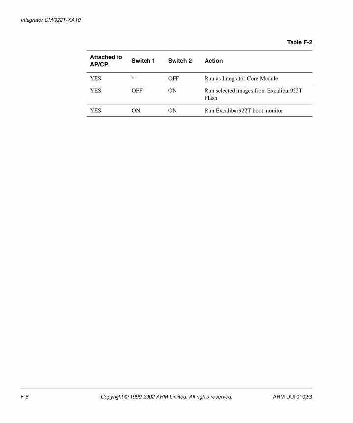
Integrator CM/922T-XA10
YES * OFF Run as Integrator Core Module
YES OFF ON Run selected images from Excalibur922T Flash
YES ON ON Run Excalibur922T boot monitor
Table F-2
Attached to AP/CP
Switch 1 Switch 2 Action
F-6 Copyright © 1999-2002 ARM Limited. All rights reserved. ARM DUI 0102G
Appendix G API Quick Reference
This appendix provides a simplified reference to the AFS APIs. It contains the following sections:
• µHAL on page G-2
• Flash APIs on page G-8
• PCI APIs on page G-13.
ARM DUI 0102G Copyright © 1999-2002 ARM Limited. All rights reserved. G-1
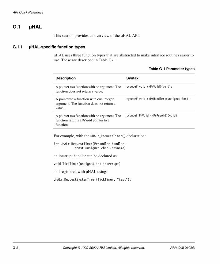
API Quick Reference
G.1 µHAL
This section provides an overview of the µHAL API.
G.1.1 µHAL-specific function types
µHAL uses three function types that are abstracted to make interface routines easier to use. These are described in Table G-1.
For example, with the uHALr_RequestTimer() declaration:
int uHALr_RequestTimer(PrHandler handler, const unsigned char *devname)
an interrupt handler can be declared as:
void TickTimer(unsigned int interrupt)
and registered with µHAL using:
uHALr_RequestSystemTimer(TickTimer, "test");
Table G-1 Parameter types
Description Syntax
A pointer to a function with no argument. The function does not return a value.
typedef void (*PrVoid)(void);
A pointer to a function with one integer argument. The function does not return a value.
typedef void (*PrHandler)(unsigned int);
A pointer to a function with no argument. The function returns a PrVoid pointer to a function.
typedef PrVoid (*PrPrVoid)(void);
G-2 Copyright © 1999-2002 ARM Limited. All rights reserved. ARM DUI 0102G
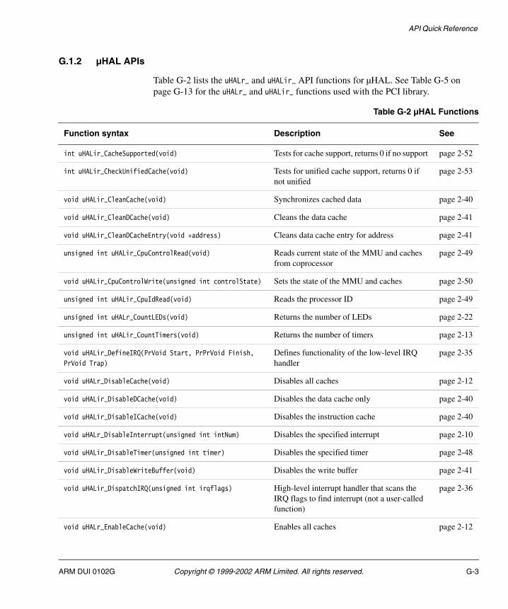
API Quick Reference
G.1.2 µHAL APIs
Table G-2 lists the uHALr_ and uHALir_ API functions for µHAL. See Table G-5 on page G-13 for the uHALr_ and uHALir_ functions used with the PCI library.
Table G-2 µHAL Functions
Function syntax Description See
int uHALir_CacheSupported(void) Tests for cache support, returns 0 if no support page 2-52
int uHALir_CheckUnifiedCache(void) Tests for unified cache support, returns 0 if not unified
page 2-53
void uHALir_CleanCache(void) Synchronizes cached data page 2-40
void uHALir_CleanDCache(void) Cleans the data cache page 2-41
void uHALir_CleanDCacheEntry(void *address) Cleans data cache entry for address page 2-41
unsigned int uHALir_CpuControlRead(void) Reads current state of the MMU and caches from coprocessor
page 2-49
void uHALir_CpuControlWrite(unsigned int controlState) Sets the state of the MMU and caches page 2-50
unsigned int uHALir_CpuIdRead(void) Reads the processor ID page 2-49
unsigned int uHALr_CountLEDs(void) Returns the number of LEDs page 2-22
unsigned int uHALir_CountTimers(void) Returns the number of timers page 2-13
void uHALir_DefineIRQ(PrVoid Start, PrPrVoid Finish,
PrVoid Trap)
Defines functionality of the low-level IRQ handler
page 2-35
void uHALr_DisableCache(void) Disables all caches page 2-12
void uHALir_DisableDCache(void) Disables the data cache only page 2-40
void uHALir_DisableICache(void) Disables the instruction cache page 2-40
void uHALr_DisableInterrupt(unsigned int intNum) Disables the specified interrupt page 2-10
void uHALir_DisableTimer(unsigned int timer) Disables the specified timer page 2-48
void uHALir_DisableWriteBuffer(void) Disables the write buffer page 2-41
void uHALir_DispatchIRQ(unsigned int irqflags) High-level interrupt handler that scans the IRQ flags to find interrupt (not a user-called function)
page 2-36
void uHALr_EnableCache(void) Enables all caches page 2-12
ARM DUI 0102G Copyright © 1999-2002 ARM Limited. All rights reserved. G-3

API Quick Reference
void uHALir_EnableDCache(void) Enables the data cache page 2-39
void uHALir_EnableICache(void) Enables the instruction cache page 2-39
void uHALr_EnableInterrupt(unsigned int intNum) Enables the specified interrupt page 2-10
void uHALir_EnableWriteBuffer(void) Enables the write buffer page 2-41
void uHALr_EnableTimer(unsigned int timer) Reloads interval and enables timer page 2-18
void *uHALr_EndOfFreeRam(void) Returns address of the last available RAM location
page 2-4
void *uHALr_EndOfRam(void) Returns address of last RAM location page 2-5
unsigned int uHALir_EnterLockedSvcMode(void) Switches into Supervisor mode and disables interrupts, returns original SPSR
page 2-44
unsigned int uHALir_EnterSvcMode(void) Goes to Supervisor mode from any mode, returns SPSR
page 2-43
void uHALir_ExitSvcMode(unsigned int spsr) Restores the original mode page 2-44
void uHALr_free(void *memPtr) Frees allocated memory (memPtr must not be -1)
page 2-6
int uHALr_FreeInterrupt(unsigned int intNum) Removes the high-level handler page 2-9
int uHALr_FreeTimer(unsigned int timer) Disables the timer, frees the interrupt, and updates the structure
page 2-16
int uHALr_getchar(void) Waits for character from default port page 2-25
unsigned int uHALir_GetSystemTimer(void) Returns the timer number defined as the system timer
page 2-48
int uHALir_GetTimerInterrupt(unsigned int timer) Allows the application to determine the correct interrupt for the specified timer
page 2-48
int uHALr_GetTimerInterval(unsigned int timer) Gets the interval in microseconds page 2-48
int uHALr_GetTimerState(unsigned int timer) Gets the current state, one of: T_FREE Available
T_ONESHOT Single-shot timer (in use)
T_INTERVAL Repeating timer (in use)
T_LOCKED Not available for use by µHAL
page 2-17
Table G-2 µHAL Functions (continued)
Function syntax Description See
G-4 Copyright © 1999-2002 ARM Limited. All rights reserved. ARM DUI 0102G

API Quick Reference
int uHALr_HeapAvailable(void) Identifies support for heap management, 0 if none
page 2-5
void uHALir_InitBSSMemory(void) Initializes any platform-specific systems that must be setup before control is passed to the application
page 2-32
void uHALr_InitHeap(void) Initializes the heap (must be called before any memory allocation or de-allocation is attempted)
page 2-5
void uHALr_InitInterrupts(void) Initializes the µHAL internal interrupt structures
page 2-8
unsigned int uHALr_InitLEDs(void) Initializes the LEDs to OFF, returns number of LEDs
page 2-22
void uHALr_InitMMU(int mode) Initializes the MMU to a default one-to-one mapping
page 2-11
void uHALr_InitSerial(unsigned int port,
unsigned int baudRate)
Initializes the specified port (specified by its base address) to the specified baud rate
page 2-26
void *uHALir_InitTargetMem(void *) Checks and initializes memory system and returns the top of memory address (do not call from C)
page 2-32
void uHALr_InitTimers(void) Initializes interrupt structure and reset timers page 2-13
void uHALr_InstallSystemTimer(void) Starts the system timer page 2-14
void uHALr_InstallTimer(unsigned int timer) Starts the specified timer page 2-14
void uHALr_LibraryInit(void) Performs system-specific initialization of µHAL when an application is linked to another library, such as the ADS C runtime library
page 2-51
void *uHALr_malloc(unsigned int size) Allocates contiguous storage, returns NULL if fails
page 2-5
int uHALr_memcmp(char *cs, char *ct, int n) Compares characters1: cs>ct, 0: cs=ct, -1: cs<ct
page 2-19
void *uHALr_memcpy(char *s, char *ct, int n) Copies characters from ct to s, returns first address copied
page 2-20
Table G-2 µHAL Functions (continued)
Function syntax Description See
ARM DUI 0102G Copyright © 1999-2002 ARM Limited. All rights reserved. G-5

API Quick Reference
void *uHALr_memset(char *s, int c, int n) Places characters into memory, returns s page 2-19
int uHALir_MMUSupported(void) Tests library for MMU support. page 2-52
int uHALir_MPUSupported(void) Tests library for MPU support. page 2-52
PrVoid uHALir_NewIRQ(PrHandler HighLevel,
PrVoid LowLevel)
Installs both the high-level and low-level IRQ routines
page 2-35
unsigned int uHALir_NewVector(void *Vector,
PrVoid LowLevel)
Replaces exception vector with the given routine pointer
page 2-34
void uHALir_PlatformInit(void) Initializes any platform-specific systems that must be setup before control is passed to the application.
page 2-32
void uHALr_printf(char *format, ...) Formats and writes to standard out, format must be one of: %i, %c, %s, %d, %u, %o, %x, or %X
page 2-26
void uHALr_putchar(char c) Sends to the default port page 2-26
unsigned int uHALir_ReadCacheMode(void) Reads MMU and cache modes page 2-42
int uHALr_ReadLED(unsigned int led) Returns TRUE if the LED is on page 2-22
unsigned int uHALir_ReadMode(void) Reads the execution mode, returns CPSR page 2-44
int uHALr_RequestInterrupt(unsigned int intNum,
PrHandler handler, const unsigned char *devname)
Assigns a high-level handler routine to the specified interrupt
page 2-9
int uHALr_RequestSystemTimer(PrHandler handler,
const unsigned char *devname)
Installs a handler for the system timer page 2-14
int uHALr_RequestTimer(PrHandler handler,
const unsigned char *devname)
Gets the next available timer and installs a handler
page 2-15
void uHALr_ResetLED(unsigned int led) Turns the specified LED off page 2-23
void uHALr_ResetMMU(void) Resets the MMU (and caches) to a fully disabled state
page 2-11
void uHALr_ResetPort(void) Sets default serial port to default baud rate page 2-25
void uHALr_SetLED(unsigned int led) Turns the specified LED on page 2-23
int uHALr_SetTimerInterval(unsigned int timer,
unsigned int interval)
Sets the interval, in microseconds page 2-17
Table G-2 µHAL Functions (continued)
Function syntax Description See
G-6 Copyright © 1999-2002 ARM Limited. All rights reserved. ARM DUI 0102G

API Quick Reference
int uHALr_SetTimerState(unsigned int timer,
enum uHALe_TimerState state)
Sets the timer state to one of:T_ONESHOT for single-shot timer (in use)T_INTERVAL for repeating timer (in use)
page 2-18
void *uHALr_StartOfRam(void) Returns the address of the first free uninitialized RAM location
page 2-4
int uHALr_strlen(const char *s) Returns the length of s page 2-20
void uHALir_TimeHandler(unsigned int irqflags) Find timer that caused interrupt, calls handler, and cancels or re-enables timer (not user callable)
page 2-47
void uHALir_TrapIRQ(void) Saves registers and handles IRQ page 2-34
void uHALir_TrapSWI(void) handles SWI exceptions (SWI_EnterOS) page 2-38
void uHALir_UnexpectedIRQ(unsigned int irq) Prints a debug message for received interrupt without installed handler
page 2-37
void uHALir_WriteCacheMode(unsigned int mode) Updates the processor MMU and cache state mode is any combination of the flags:EnableMMU to enable the MMUIC_ON to turn the ICache onDC_ON to turn the DCache onWB_ON to turn the Write Buffer on
page 2-42
int uHALr_WriteLED(unsigned int led,
unsigned int state)
Writes a value to the LED page 2-23
void uHALir_WriteMode(unsigned int cpsr) Changes the execution mode page 2-45
Table G-2 µHAL Functions (continued)
Function syntax Description See
ARM DUI 0102G Copyright © 1999-2002 ARM Limited. All rights reserved. G-7

API Quick Reference
G.2 Flash APIs
The following examples (Example G-1 to Example G-4 on page G-9) show the flash structure definitions.
Example G-1 FlashPhysicalType structure
typedef struct flashPhysicalType{ char *base; // Virtual address of flash for reads (normal access)char *writeBase; // Virtual address of flash for writeschar *physicalBase; // This is the location where flash can be accessed // _before_ any memory management is enabledunsigned32 width; // Width of flash access on this platform (bits)unsigned32 parallel; // Number of devices in parallel across databusunsigned32 size; // Size of flash, in bytesunsigned32 type; // Atmel / Intel (CFI) / AMD / Unknownunsigned32 writeSize; // Size of physical blockunsigned32 eraseSize; // Size of block eraseunsigned32 logicalSize; // Size of logical block
// Pointers to routines which perform operations on this deviceflFlash_WriteProc *write; // Write one wordflFlash_WriteBlockProc *writeBlock; // Write a block of writeSize bytesflFlash_ReadProc *read; // Read one wordflFlash_ReadBlockProc *readBlock; // Read a block of writeSize bytesflFlash_EraseProc *erase; // Erase a block of eraseSize bytesflFlash_InitProc *init; // Unlock a flash deviceflFlash_CloseProc *close; // Lock a flash deviceflFlash_QueryProc *query; // Query a flash device (reads size etc)char info[64]; // Null terminated Info stringstruct flashPhysicalType *next; // Pointer to next flash device}tPhysicalFlash;
G-8 Copyright © 1999-2002 ARM Limited. All rights reserved. ARM DUI 0102G

API Quick Reference
Example G-2 FlashType structure
typedef struct flashType{ struct flashPhysicalType *devices; // Pointer to physical device listunsigned32 offset; // Number of blocks into the deviceunsigned32 bsize; // Size of flash, in blocksunsigned32 type; // Boot/Application typestruct flashType *next; // Pointer to next flash device} tFlash;
Example G-3 Footer structure
typedef struct FooterType { void *infoBase; // Address of first word of ImageFooter char *blockBase; // Start of area reserved by this footer unsigned int signature; // 'Magic' number to prove it's a footer unsigned int type; // Area type: ARM image, SIB, customer unsigned int checksum; // Checksum of this structure only} tFooter;
Example G-4 SIB structure
typedef struct SIBInfoType{ unsigned32 SIB_number; // Unique number of SIB Block unsigned32 SIB_Extension; // Base of SIB flash block char Label[16]; // String space for ownership string unsigned32 checksum; // SIB Image checksum} tSIBInfo;
ARM DUI 0102G Copyright © 1999-2002 ARM Limited. All rights reserved. G-9

API Quick Reference
Table G-3 describes functions related to the flash library.
Table G-3 Flash library functions
Function syntax Description See
int fLib_BuildFooter(tFooter *foot, tFlash *flashmem) Builds a footer for the specified image
page 6-34
int fLib_ChecksumFooter(tFooter *foot, unsigned int *foot_sum,
unsigned int *image_sum, tFlash *flashmem)
Calculates the checksum for the specified image footer
page 6-29
int fLib_ChecksumImage(tFooter *foot, unsigned int *image_sum,
tFlash *flashmem)
Calculates the checksum for the specified image
page 6-29
int fLib_CloseFile(File *file, tFile_Io *file_IO) Closes the file on the host page 6-37
int fLib_CloseFlash(tFlash *flashmem) Finalizes the flash device for this platform
page 6-21
int fLib_DeleteArea(unsigned int *address, unsigned int size,
tFlash *flashmem)
Deletes (erases) an area of flash memory
page 6-24
int fLib_DefinePlat(tFooter *foot) Defines logical structures used by the library
page 6-28
int fLib_DeleteImage(tFooter *foot) Deletes the image in flash page 6-28
int fLib_ExecuteImage(tFooter *foot) Executes the image selected page 6-27
unsigned int fLib_FindFlash(tFlash **tf) Locates the flash devices page 6-20
unsigned int fLib_FindFooter(unsigned int *start,
unsigned int size, tFooter *list[], tFlash *flashmem)
Scans flash memory and returns a list of pointers to image footers
page 6-33
int fLib_FindImage(tFooter **list, unsigned int imageNo,
tFooter *foot, tFlash *flashmem)
Scans flash footers for a footer with matching image number
page 6-27
unsigned int fLib_GetBlockSize(tFlash *flashmem) Returns size, in bytes, of the logical block
page 6-24
int fLib_GetEmptyArea(tFooter **list, unsigned int empty,
tFlash *flashmem)
Scans flash footers for empty area page 6-31
int fLib_GetEmptyFlash(tFooter **list, unsigned int *start,
unsigned int *location, unsigned int empty, tFlash *flashmem)
Scans the list of flash footers, looking for an empty area from start, of at least unused size
page 6-30
int fLib_initFooter(tFooter *foot, int ImageSize, int type) Initializes the footer with known values
page 6-31
G-10 Copyright © 1999-2002 ARM Limited. All rights reserved. ARM DUI 0102G

API Quick Reference
File *fLib_OpenFile(char *filename, char *mode,
tFile_IO *file_IO)
Opens a file page 6-36
int fLib_OpenFlash(tFlash *flashmem) Initializes the flash device for this platform
page 6-21
int fLib_ReadArea(unsigned int *address, unsigned int *data,
unsigned int size, tFlash *flashmem)
Reads an area of size bytes from flash memory
page 6-23
unsigned int fLib_ReadFile(unsigned int *value,
unsigned int size, tImageInfo *image, tFile_IO *file_IO)
Reads (and converts) an area of size bytes from the open file
page 6-38
unsigned int fLib_ReadFileHead(File *file, tImageInfo *image,
unsigned int *size, tFile_IO *file_IO)
Reads the file header, determines the file type, and sets fields in image from the data
page 6-37
unsigned int fLib_ReadFileRaw(unsigned int *value,
unsigned int size, tFile_IO *file_IO, tFILE *fp)
Reads up to size bytes from the open file fp
page 6-35
int fLib_ReadFlash32(unsigned int *address,
unsigned int *value, tFlash *flashmem)
Reads one 32-bit word from the flash at given address
page 6-22
int fLib_ReadFooter(unsigned int *start, tFooter *foot,
tFlash *flashmem)
Reads the footer at start in flash to foot in memory
page 6-32
int fLib_ReadImage(tFooter *foot, tFlash *flashmem) Reads the image from flash page 6-25
int fLib_UpdateChecksum(tFooter *foot, unsigned int im_check,
unsigned int ft_check, tFlash *flashmem)
Verifies the footer at foot page 6-33
int fLib_VerifyFooter(tFooter *foot, tFlash *flashmem) Verifies the footer at foot page 6-33
int fLib_VerifyImage(tFooter *foot, tFlash *flashmem) Verifies that image structure matches programmed image
page 6-26
int fLib_WriteArea(unsigned int *address, unsigned int *data,
unsigned int size, tFlash *flashmem)
Writes an area of size bytes to flash memory
page 6-23
int Flash_Write_Disable(int type) Locks all devices of type page 6-19
int Flash_Write_Enable(int type) Unlocks all devices of type page 6-19
unsigned int fLib_WriteFile(unsigned int *value,
unsigned int size, tImage *image, tFile_IO *file_IO)
Converts and writes from the open file
page 6-39
unsigned int fLib_WriteFileHead(File *file,
tImageInfo *image, tFile_IO *file_IO)
Writes the header in image->footer to file
page 6-38
Table G-3 Flash library functions (continued)
Function syntax Description See
ARM DUI 0102G Copyright © 1999-2002 ARM Limited. All rights reserved. G-11

API Quick Reference
Table G-4 lists the SIB functions.
unsigned int fLib_WriteFileRaw(unsigned int *value,
unsigned int size, tFile_IO *file_IO, tFILE *fp)
Writes up to size bytes to the open file fp
page 6-35
int fLib_WriteFlash32(unsigned int *address,
unsigned int value, tFlash *flashmem)
Writes one 32-bit word to the flash at the given address
page 6-22
int fLib_WriteFooter(tFooter *foot, tFlash *flashmem,
unsigned int *foot_data, unsigned int *image_data)
Writes a footer to flash memory page 6-32
int fLib_WriteImage(tFooter *foot, tFlash *flashmem) Writes image selected by structure page 6-25
Table G-3 Flash library functions (continued)
Function syntax Description See
Table G-4 SIB functions
Function syntax Description See
int SIB_Close(char *idString) Frees SIB access page 6-43
int SIB_Copy(int sibIndex, void *dataBlock, int dataSize) Gets a local copy of the user data in a SIB
page 6-44
int SIB_Erase(int sibIndex) Erases the SIB page 6-46
int SIB_GetPointer(int sibIndex, void **dataBlock) Gets the start address of SIB user data
page 6-43
int SIB_GetSize(int sibIndex, int *dataSize) Gets the size of SIB data page 6-45
int SIB_Open(char *idString, int *sibCount, int privFlag) Scans flash for SIB blocks and indexes the SIBs in a linked list for faster access
page 6-42
int SIB_Program(int sibIndex, void *dataBlock, int dataSize) Creates a new SIB or updates an existing SIB with new user data
page 6-44
int SIB_Verify(int sibIndex) Verifies the SIB by checking the signature and checksum
page 6-45
G-12 Copyright © 1999-2002 ARM Limited. All rights reserved. ARM DUI 0102G

API Quick Reference
G.3 PCI APIs
Table G-5 and Table G-6 on page G-14 describe functions related to the PCI library.
Table G-5 µHAL PCI functions
Function syntax Description See
volatile unsigned char uHALr_PCICfgRead8(unsigned int bus,
unsigned int slot, unsigned int func, unsigned int offset)
Reads 8 bits from PCI Configuration space
page 8-18
volatile unsigned short uHALr_PCICfgRead16(unsigned int bus,
unsigned int slot, unsigned int func, unsigned int offset)
Reads 16 bits from PCI Configuration space
page 8-18
volatile unsigned int uHALr_PCICfgRead32(unsigned int bus,
unsigned int slot, unsigned int func, unsigned int offset) Reads 32 bits from PCI Configuration space
page 8-19
void uHALr_PCICfgWrite8(unsigned int bus, unsigned int slot,
unsigned int func, unsigned int offset, unsigned char data)
Writes 8 bits to PCI Configuration space
page 8-19
void uHALr_PCICfgWrite16(unsigned int bus, unsigned int slot,
unsigned int func, unsigned int offset, unsigned short data)
Writes 16 bits to PCI Configuration space
page 8-19
void uHALr_PCICfgWrite32(unsigned int bus, unsigned int slot,
unsigned int func, unsigned int offset, unsigned int data)
Writes 32 bits to PCI Configuration space
page 8-20
unsigned char uHALr_PCIHost(void) Tests the board for PCI support page 8-17
void uHALir_PCIInit(void) Initializes the host bridge page 8-17
volatile unsigned char uHALr_PCIIORead8(unsigned int offset) Reads 8 bits from PCI I/O space page 8-20
volatile unsigned short uHALr_PCIIORead16(unsigned int offset) Writes 16 bits from PCI I/O space page 8-21
volatile unsigned int uHALr_PCIIORead32(unsigned int offset) Reads 32 bits from PCI I/O space page 8-21
void uHALr_PCIIOWrite8(unsigned int offset, unsigned char data) Writes 8 bits to PCI I/O space page 8-21
void uHALr_PCIIOWrite16(unsigned int offset, unsigned short data) Writes 16 bits to PCI I/O space. page 8-22
void uHALr_PCIIOWrite32(unsigned int offset, unsigned int data) Writes 32 bits to PCI I/O space. page 8-22
unsigned char uHALir_PCIMapInterrupt(unsigned char pin,
unsigned char slot)
Returns interrupt number for PCI slot and interrupt pin
page 8-22
ARM DUI 0102G Copyright © 1999-2002 ARM Limited. All rights reserved. G-13
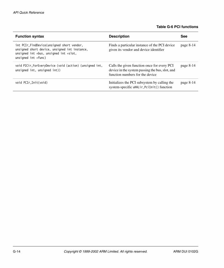
API Quick Reference
Table G-6 PCI functions
Function syntax Description See
int PCIr_FindDevice(unsigned short vendor, unsigned short device, unsigned int instance, unsigned int *bus, unsigned int *slot, unsigned int *func)
Finds a particular instance of the PCI device given its vendor and device identifier
page 8-14
void PICir_ForEveryDevice (void (action) (unsigned int,
unsigned int, unsigned int))
Calls the given function once for every PCI device in the system passing the bus, slot, and function numbers for the device
page 8-14
void PCIr_Init(void) Initializes the PCI subsystem by calling the system-specific uHALir_PciInit() function
page 8-14
G-14 Copyright © 1999-2002 ARM Limited. All rights reserved. ARM DUI 0102G
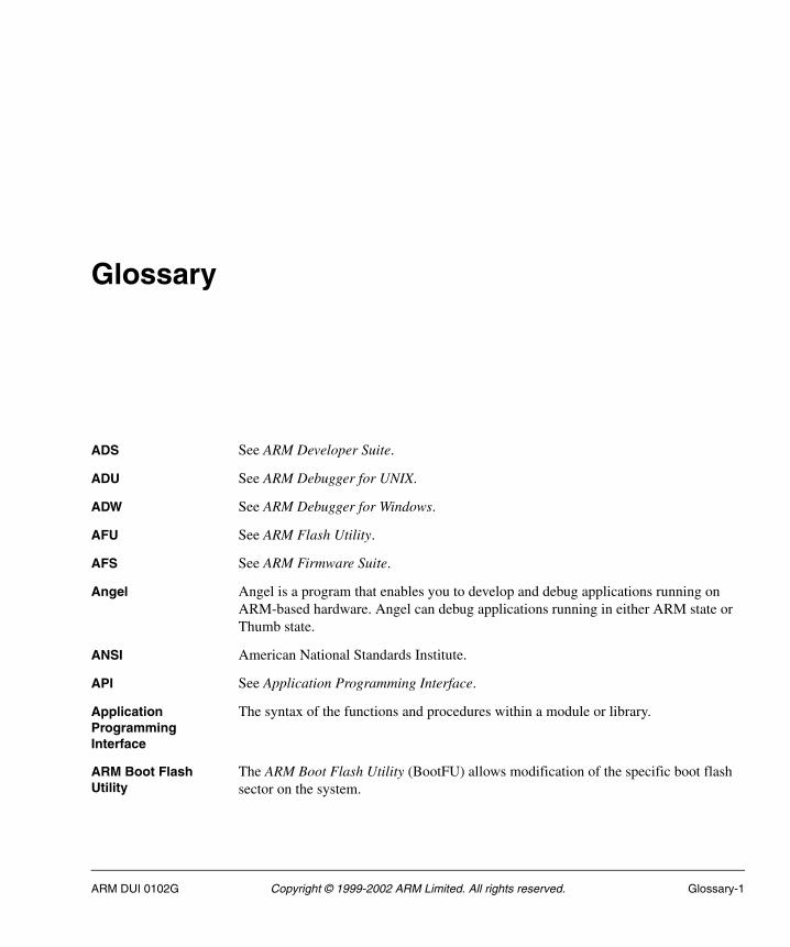
Glossary
ADS See ARM Developer Suite.
ADU See ARM Debugger for UNIX.
ADW See ARM Debugger for Windows.
AFU See ARM Flash Utility.
AFS See ARM Firmware Suite.
Angel Angel is a program that enables you to develop and debug applications running on ARM-based hardware. Angel can debug applications running in either ARM state or Thumb state.
ANSI American National Standards Institute.
API See Application Programming Interface.
Application Programming Interface
The syntax of the functions and procedures within a module or library.
ARM Boot Flash Utility
The ARM Boot Flash Utility (BootFU) allows modification of the specific boot flash sector on the system.
ARM DUI 0102G Copyright © 1999-2002 ARM Limited. All rights reserved. Glossary-1

Glossary
ARM Debugger for UNIX
The ARM Debugger for UNIX (ADU) and ARM Debugger for Windows (ADW) are two versions of the same ARM debugger software, running under UNIX or Windows respectively.
ARM Debugger for Windows
See ARM Debugger for Unix.
ARM Developer Suite
A suite of applications, together with supporting documentation and examples, that enable you to write and debug applications for the ARM family of RISC processors.
ARM eXtendable Debugger
The ARM eXtendable Debugger (AXD) is the latest debugger software from ARM that enables you to make use of a debug agent in order to examine and control the execution of software running on a debug target. AXD is supplied in both Windows and UNIX versions.
ARM Firmware Suite A collection of utilities to assist in developing applications and operating systems on ARM-based systems.
ARM Flash Utility The ARM Flash Utility (AFU) is an application for manipulating and storing data within a system that uses the flash library.
armsd The ARM Symbolic Debugger (armsd) is an interactive source-level debugger providing high-level debugging support for languages such as C, and low-level support for assembly language. It is a command-line debugger that runs on all supported platforms.
ARMulator ARMulator is an instruction set simulator. It is a collection of modules that simulate the instruction sets and architecture of various ARM processors.
ATPCS The ARM and Thumb Procedure Call Standard (ATPCS) defines how registers and the stack are used for subroutine calls.
AXD See ARM eXtendable Debugger.
Big-Endian Memory organization where the least significant byte of a word is at a higher address than the most significant byte. See also Little-Endian.
BootFU See ARM Boot Flash Utility.
Boot monitor A ROM-based monitor that communicates with a host computer using simple commands over a serial port. Typically this application is used to display the contents of memory and provide system debug and self-test functions.
Boot switcher The boot switcher selects and runs an image in application flash. You can store one or more code images in flash memory and use the boot switcher to start the image at reset.
Canonical Frame Address
In DWARF 2, this is an address on the stack specifying where the call frame of an interrupted function is located.
Glossary-2 Copyright © 1999-2002 ARM Limited. All rights reserved. ARM DUI 0102G
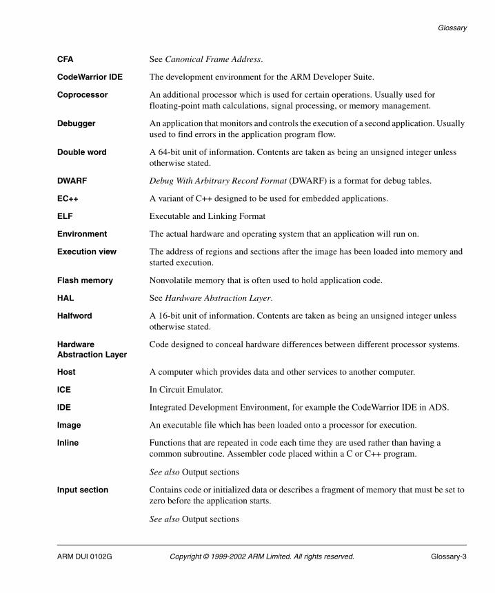
Glossary
CFA See Canonical Frame Address.
CodeWarrior IDE The development environment for the ARM Developer Suite.
Coprocessor An additional processor which is used for certain operations. Usually used for floating-point math calculations, signal processing, or memory management.
Debugger An application that monitors and controls the execution of a second application. Usually used to find errors in the application program flow.
Double word A 64-bit unit of information. Contents are taken as being an unsigned integer unless otherwise stated.
DWARF Debug With Arbitrary Record Format (DWARF) is a format for debug tables.
EC++ A variant of C++ designed to be used for embedded applications.
ELF Executable and Linking Format
Environment The actual hardware and operating system that an application will run on.
Execution view The address of regions and sections after the image has been loaded into memory and started execution.
Flash memory Nonvolatile memory that is often used to hold application code.
HAL See Hardware Abstraction Layer.
Halfword A 16-bit unit of information. Contents are taken as being an unsigned integer unless otherwise stated.
Hardware Abstraction Layer
Code designed to conceal hardware differences between different processor systems.
Host A computer which provides data and other services to another computer.
ICE In Circuit Emulator.
IDE Integrated Development Environment, for example the CodeWarrior IDE in ADS.
Image An executable file which has been loaded onto a processor for execution.
Inline Functions that are repeated in code each time they are used rather than having a common subroutine. Assembler code placed within a C or C++ program.
See also Output sections
Input section Contains code or initialized data or describes a fragment of memory that must be set to zero before the application starts.
See also Output sections
ARM DUI 0102G Copyright © 1999-2002 ARM Limited. All rights reserved. Glossary-3

Glossary
Interworking Producing an application that uses both ARM and Thumb code.
Library A collection of assembler or compiler output objects grouped together into a single repository.
Linker Software which produces a single image from one or more source assembler or compiler output objects.
Little-endian Memory organization where the least significant byte of a word is at a lower address than the most significant byte. See also Big-endian.
Load view The address of regions and sections when the image has been loaded into memory but has not yet started execution.
Local An object that is only accessible to the subroutine that created it.
Memory management unit
Hardware that controls caches and access permissions to blocks of memory, and translates virtual to physical addresses.
Memory protection unit
Hardware that controls permissions to blocks of memory. Unlike an MMU, a MPU does not translate virtual addresses to physical addresses.
MMU See Memory Management Unit.
MPU See Memory Protection Unit.
Multi-ICE Multi-processor JTAG emulator. ARM registered trademark.
Output section Is a contiguous sequence of input sections that have the same Read Only, Read Write, or Zero Initialized attributes. The sections are grouped together in larger fragments called regions. The regions will be grouped together into the final executable image.
See also Region
PCI See Peripheral Component Interconnect.
PCS Procedure Call Standard.
See also ATPCS
Peripheral Component Interconnect
An expansion bus used with PCs and workstations.
PIC Position Independent Code.
See also ROPI
PID Position Independent Data.
See also RWPI
Glossary-4 Copyright © 1999-2002 ARM Limited. All rights reserved. ARM DUI 0102G

Glossary
Profiling Accumulation of statistics during execution of a program being debugged, to measure performance or to determine critical areas of code.
Call-graph profiling provides great detail but slows execution significantly. Flat profiling provides simpler statistics with less impact on execution speed.
For both types of profiling you can specify the time interval between statistics-collecting operations.
Program image See Image.
Reentrancy The ability of a subroutine to have more that one instance of the code active. Each instance of the subroutine call has its own copy of any required static data.
Regions In an Image, a region is a contiguous sequence of one to three output sections (Read Only, Read Write, and Zero Initialized).
Remapping Changing the address of physical memory or devices after the application has started executing. This is typically done to allow RAM to replace ROM once the initialization has been done.
Retargeting The process of moving code designed for one execution environment to a new execution environment.
ROPI Read Only Position Independent. Code and read-only data addresses can be changed at run-time.
RTOS Real Time Operating System.
RWPI Read Write Position Independent. Read/write data addresses can be changed at run-time.
Scatter loading Assigning the address and grouping of code and data sections individually rather than using single large blocks.
Scope The accessibility of a function or variable at a particular point in the application code. Symbols which have global scope are always accessible. Symbols with local or private scope are only accessible to code in the same subroutine or object.
Section A block of software code or data for an Image.
See also Input sections
Semihosting A mechanism whereby the target communicates I/O requests made in the application code to the host system, rather than attempting to support the I/O itself.
SIB See System Information Block.
SWI Software Interrupt. An instruction that causes the processor to call a programer-specified subroutine. Used by ARM to handle semihosting.
ARM DUI 0102G Copyright © 1999-2002 ARM Limited. All rights reserved. Glossary-5
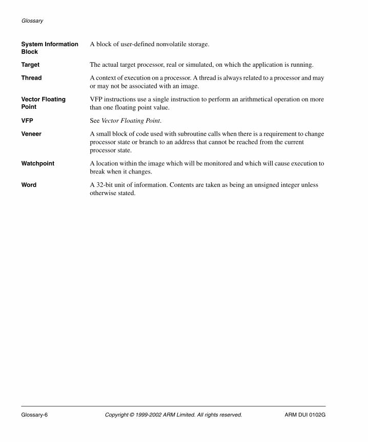
Glossary
System Information Block
A block of user-defined nonvolatile storage.
Target The actual target processor, real or simulated, on which the application is running.
Thread A context of execution on a processor. A thread is always related to a processor and may or may not be associated with an image.
Vector Floating Point
VFP instructions use a single instruction to perform an arithmetical operation on more than one floating point value.
VFP See Vector Floating Point.
Veneer A small block of code used with subroutine calls when there is a requirement to change processor state or branch to an address that cannot be reached from the current processor state.
Watchpoint A location within the image which will be monitored and which will cause execution to break when it changes.
Word A 32-bit unit of information. Contents are taken as being an unsigned integer unless otherwise stated.
Glossary-6 Copyright © 1999-2002 ARM Limited. All rights reserved. ARM DUI 0102G

Index
The items in this index are listed in alphabetical order, with symbols and numerics appearing at the end. The references given are to page numbers.
AAAED-2000 board
boot monitor E-6image formats E-6using Flash memory E-6
Access primitives, PCI 8-16Accessing flash 6-5ADP 5-46AFS
about 1-2AFU
operation 7-3user commands 7-4
AFU commandsDelete All 7-13Delete Block command 7-12Diagnostic List 7-6Diagnostic List Footer 7-7Help command 7-18Identify 7-19List 7-5
ARM DUI 0102G Copyright © 1999-2002 ARM Limited. All rights reserved. Index-1

List All 7-6Program Image 7-13Read image 7-17Test Block 7-11
ambauart.h source file 5-10Angel
AAED-2000 E-9and exception handling 5-29angel_SWIChain 10-5angel_SWIInfo 10-3Boot channel 5-46boot support 5-47breakpoint restrictions 5-36breakpoint setting 5-30buffer lifecycle 5-49buffer management 5-48building 5-11C library support 5-30cache memory 5-4chain initialization 10-9, 10-11channel restrictions 5-48channels layer 5-48channels packet format 5-50communications layers 5-46communications support 5-6, 5-31context switching 5-41DCC 5-32debug support 5-5debugger functions 5-35device driver layer 5-51downloading A-25enabling assertions 5-30Evaluator-7T D-8exception handling 5-7exception vectors 5-3HAL 5-2heartbeat mechanism 5-50initialization 5-33Integrator A-24interrupt table 5-29IQ80310 C-10memory requirements 5-3planning development 5-26programming restrictions 5-27Prospector B-10raw serial drivers 5-31reporting memory and processor status 5-35and RTOSes 5-27semihosting support 5-5, 5-27
Index-2 Copyright © 1999-2002 ARM Limited. All rights reserved. ARM DUI 0102G
setting breakpoints 5-36source file descriptions 5-13sources and definitions 5-10stacks 5-4, 5-43supervisor mode 5-28supervisor stack 5-27task management 5-6, 5-34, 5-37, 5-42task management functions 5-39task priorities 5-37task queue 5-42Task Queue Items 5-41Thumb debug communications channel 5-32undefined instruction 5-27
Angel source filebanner.h 5-13devices.c 5-14makelo.c 5-16serial.c 5-17target.s 5-17timerdev.c 5-16
Angel_BlockApplication() 5-39Angel_NewTask() 5-38, 5-39, 5-43Angel_NextTask() 5-38, 5-40, 5-45Angel_QueueCallback() 5-38Angel_SelectNextTask() 5-40, 5-43, 5-45Angel_SerialiseTask() 5-37, 5-42, 5-43, 5-45Angel_Signal() 5-39, 5-40Angel_TaskID() 5-39, 5-41angel_TQ_Pool 5-42Angel_Wait() 5-39, 5-40, 5-42Angel_Yield() 5-39, 5-40, 5-42API
extemded functions 2-3extended coprocessor functions 2-49extended initialization 2-31extended MMU functions 2-39extended timer functions 2-46flash library 6-14MMU and cache 2-11PCI 8-8processor mode functions 2-43simple functions 2-3simple interrupt functions 2-33simple LED functions 2-21simple serial I/O functions 2-25simple support functions 2-19simple timer functions 2-13SWI function 2-38
ARM Boot Monitor, see Boot monitor
ARM DUI 0102G Copyright © 1999-2002 ARM Limited. All rights reserved. Index-3
ARM Flash Library 6-2ARM Flash Utility, see AFUARM Project files 11-3ARM support xiiiAssertions, and Angel debugging 5-30ASSERT_ENABLED macro 5-30Assigning PCI interrupt numbers 8-13Assigning resources to PCI devices 8-11
Bbanner.h source file 5-10Base address for PCI IO space 8-12Base address for PCI Memory space 8-12Baud rate, setting 3-5Board-specific command mode 3-11Boot monitor
functions 3-3hardware accesses 3-2Integrator A-6overview 3-2
Boot monitor commandsAAED-2000-specific E-3display AAED-2000 help E-4display Evaluator-7T help D-4display help 3-7display Integrator clocks A-12display Integrator hardware A-15display Integrator help A-18display IQ80310 help C-5display memory B-3, C-4, D-3, E-3display PCI configuration A-11display PCI I/O A-10display PCI memory A-10display PCI topology A-8, A-10, A-11display Prospector help B-4display system memory 3-6display V3 setup A-7enter board specific command mode 3-11erase system flash 3-6Evaluator-7T-specific D-3exit command mode B-5, C-6, D-5, E-5go to address A-16, B-3, C-4, D-4, E-4identify the system 3-7initialize PCI subsystem A-7IQ80310-specific C-4load S-records into flash 3-7poke memory B-4, C-5, D-4, E-4
Index-4 Copyright © 1999-2002 ARM Limited. All rights reserved. ARM DUI 0102G

Prospector-specific B-3run image A-18, B-4, C-5, D-4, E-4set baud rate 3-5set core clock A-14, A-17set default flash boot image number 3-5set Integrator clocks A-12system self tests 3-9upload an image into memory 3-8validate flash 3-10view images B-4, C-5, D-4, E-4
Boot switcherset default boot image 3-5
BootFU commandsclear 7-28diagnosticList 7-23help 7-22identify 7-27list 7-23messages 7-28overview 7-22program 7-24quit 7-27read 7-27
BOOTP 9-2Breakpoints
and Angel 5-36Angel restrictions 5-36MultiICE and EmbeddedICE 5-36
Buildingboot monitor 3-12HAL-based Angel 5-11libraries 11-3using GNU make 11-3
CC library
and Angel 5-30support 11-13
Cachelibrary function 2-52
Chainingstructure 10-8
Chaining exception handlersand Angel 5-29
ChannelsAngel channel restrictions 5-48
Code image area, flash 6-2
ARM DUI 0102G Copyright © 1999-2002 ARM Limited. All rights reserved. Index-5

Code portability 6-5Codewarrior IDE 11-3Communications
Angel communications architecture 5-46Context switch
and Angel 5-41Coprocessor access functions 2-49
DData structures, PCI 8-9Debugging
Angel assertions 5-30devconf.h 5-35devconf.h source file 5-10Device driver layer (Angel) 5-51devices.c source file 5-10DHCP
BOOTP 9-2introduction 9-1
Directoriesbuilding libraryies 11-3naming 11-2
Display system memory command 3-6Download to flash 6-14
EErase system flash command 3-6Evaluator-7T board
boot monitor D-6using Flash memory D-6
Exception handlersand Angel 5-29
Exceptionsand Angel 5-29chaining 10-1
Extended API functions 2-3External file translation interface, flash 6-17
FFeedback xiiiFile headers and formats, flash 6-17Files
devconf.h 5-35
Index-6 Copyright © 1999-2002 ARM Limited. All rights reserved. ARM DUI 0102G
serlasm.s 5-39serlock.h 5-39
Finding flash 6-47FIQ
and Angel 5-4, 5-27Fixed AIF 7-2Flash 6-14
AAED-2000 board E-6accessing 6-5block access 6-15Evaluator-7T board D-6executing an image 6-49file formats 6-17file processing functions 6-16, 6-35footer information 6-2footer structure 6-11formatted files 6-17image footers 6-16image information 6-2image management 6-10image structure 6-12images 6-15Integrator board A-19IQ80310 board C-7library and memory structure 6-2library functions 6-19library functions by type 6-14library specifications 6-5library usage 3-2locating 6-14logical device structure 6-9management, overview 6-4physical device structure 6-6preparing and programming an image 6-48Prospector board B-6reading a file into memory 6-47reading an image to a file 6-48simple file access 6-16single word access 6-15System Information Block 6-40types 6-10validate 3-10
Flash Library functionsFlash_Write_Disable() 6-19Flash_Write_Enable() 6-19fLib_BuildFooter() 6-34fLib_ChecksumFooter() 6-29fLib_ChecksumImage() 6-28fLib_CloseFile() 6-37
ARM DUI 0102G Copyright © 1999-2002 ARM Limited. All rights reserved. Index-7

fLib_DefinePlat() 6-20fLib_DeleteArea() 6-24fLib_DeleteImage() 6-28fLib_ExecuteImage() 6-27fLib_FindFlash() 6-20fLib_FindFooter() 6-33fLib_FindImage() 6-27fLib_GetBlockSize() 6-24fLib_GetEmptyArea() 6-31fLib_GetEmptyFlash() 6-30fLib_initFooter() 6-31fLib_OpenFile() 6-36fLib_OpenFlash() 6-21fLib_ReadArea() 6-23fLib_ReadFileHead() 6-37fLib_ReadFileRaw() 6-35fLib_ReadFile() 6-38fLib_ReadFlash32() 6-22fLib_ReadFooter() 6-32fLib_ReadImage() 6-25fLib_UpdateChecksum() 6-29fLib_VerifyFooter() 6-33fLib_VerifyImage() 6-26fLib_WriteArea() 6-23fLib_WriteFileHead() 6-38fLib_WriteFileRaw() 6-35fLib_WriteFile() 6-39fLib_WriteFlash32() 6-22fLib_WriteFooter() 6-32fLib_WriteImage() 6-25quick reference G-10SIB_Close() 6-43SIB_Copy() 6-44SIB_Erase() 6-46SIB_GetPointer() 6-43SIB_GetSize() 6-45SIB_Open() 6-42SIB_Program() 6-44SIB_Verify() 6-45
Footer information, flash 6-2Formatted file access, flash 6-17Further reading xi
GGETSOURCE macro 5-45
Index-8 Copyright © 1999-2002 ARM Limited. All rights reserved. ARM DUI 0102G

HHAL
Angel 5-9API 2-2coprocessor functions, extended 2-49initialization functions, extended 2-31interrupt functions 2-8interrupt handling functions, extended 2-33LED functions 2-21memory functions 2-4MMU and cache extended API 2-39MMU and cache, simple API 2-11parameter types 2-2, G-2PCI extensions 8-16PCI functions 8-16processor execution mode functions 2-43serial I/O functions 2-25simple API functions 2-3, 2-4simple API interrupt functions 2-8simple API LED control functions 2-21support functions 2-19SWI fuction, extended 2-38timer functions 2-13timer functions, extended 2-46
HANDLE_INTERRUPTS_ON_FIQ 5-45Hardware accesses
boot monitor 3-2Header information, flash 6-2Heartbeats (Angel) 5-50Help
AFU 7-18boot monitor 3-7BootFU 7-22
Host bridge initialization, PCI 8-11
IIdentify the system command 3-7Image information, flash 6-2Initializing
API functions 2-31memory in boot monitor 3-2PCI 8-8simple operating system 4-4
Integrator boardloading Angel A-24PCI initilization A-2, A-26
ARM DUI 0102G Copyright © 1999-2002 ARM Limited. All rights reserved. Index-9
using flash memory A-19integrator.h source file 5-10Interrupt
and Angel 5-44assigning PCI 8-13extended API 2-33handling functions 2-33routing PCI 8-16simple API functions 2-8
IQ80310 boardboot monitor C-7using Flash memory C-7
IRQand Angel 5-4, 5-27Angel processing of 5-44
LLED
control code example 2-24Integrator A-21
Librarygeneric 11-2naming 11-2
LicensingC/OS-II 4-4
LinkingAngel C libraries 5-30
Load S-records into flash command 3-7Locating flash 6-14
MMakefile
GNU 11-3makelo.c source file 5-10Memory
API functions 2-4boot monitor initilization 3-2extended MMU and cache API 2-39initialization in boot monitor 3-2MMU and cache example 2-12MMU library support 2-52simple MMU and cache API 2-11
Motorola S-record 7-2loader 3-4
MultiICE and EmbeddedICE
Index-10 Copyright © 1999-2002 ARM Limited. All rights reserved. ARM DUI 0102G

Breakpoints 5-36
OOperating system
complex 4-2, 4-11context switching 4-6C/OS 4-2efficiency considerations 4-10Linux 4-2porting 4-11simple 4-2
PPCI
about 8-2address spaces 8-4configuration 8-4configuration header 8-5configuration space 8-4data structures 8-9definitions 8-15device driver example 8-23function descriptions 8-17HAL extensions 8-16host bridge 8-3Host bridge initialization 8-11host bus 8-3ISA bridge 8-3I/O space 8-6library 8-8library data structure 8-10library functions 8-14memory space 8-6overview 8-2PCI bridge 8-3, 8-6primary bus 8-3resource allocation 8-16resources 8-11scanning 8-11secondary bus 8-3subsystem initialization 8-8Type 0 configuration cycle 8-5Type 1 configuration cycle 8-6
PCI functionsPCIr_FindDevice 8-14
ARM DUI 0102G Copyright © 1999-2002 ARM Limited. All rights reserved. Index-11

PCIr_ForEveryDevice() 8-14PCIr_Init() 8-14quick reference G-13uHALir_PCIInit 8-17uHALir_PCIMapInterrupt 8-22uHALr_PCICfgRead16 8-18uHALr_PCICfgRead32 8-19uHALr_PCICfgRead8 8-18uHALr_PCICfgWrite16 8-19uHALr_PCICfgWrite32 8-20uHALr_PCICfgWrite8 8-19uHALr_PCIHost 8-17uHALr_PCIIORead16 8-21uHALr_PCIIORead32 8-21uHALr_PCIIORead8 8-20uHALr_PCIIOWrite16 8-22uHALr_PCIIOWrite32 8-22uHALr_PCIIOWrite8 8-21
Prefetch abortand Angel 5-29, 5-7
Processor execution mode functions 2-43Processor mode
and Angel stacks 5-43Prospector board
boot monitor B-6image formats B-6PCI initilization B-2using Flash memory B-6
RRB_ Angel register blocks 5-42Related publications xiRelocatable AIF 7-2ROADDR (Angel) 5-33RTOS
and Angel 5-27and context switching 5-41
RunningAFU 7-3boot monitor 3-4BootFU 7-20
RWADDR (Angel) 5-33
SScanning the PCI system 8-11
Index-12 Copyright © 1999-2002 ARM Limited. All rights reserved. ARM DUI 0102G

Semihosting 5-5enabling and disabling 5-6and programming restrictions 5-27
Serial portexample 2-26functions 2-25
serial.c source file 5-10serlasm.s 5-39serlock.h 5-39Set baud rate command 3-5Set boot image command 3-5Setting up AFU 7-3SIB functions
SIB_Close() 6-43SIB_Copy() 6-44SIB_Erase() 6-46SIB_GetPointer() 6-43SIB_GetSize() 6-45SIB_Open() 6-42SIB_Program() 6-44SIB_Verify() 6-45
Simple API functions 2-3Simple file access, flash 6-16Software interrupt (SWI) function 2-38Source files
Angel 5-9, 5-13Stacks
Angel 5-43Starting up flash 6-47Supervisor mode
and Angel 5-28Support functions 2-19SWI
C library support 5-5SWI interface
chaining 10-3System information block, see SIBSystem self test 3-4
command 3-9System timer programming example 2-15
TTask management
Angel 5-37Task Queue Items 5-41Terminal emulator
boot monitor 3-2
ARM DUI 0102G Copyright © 1999-2002 ARM Limited. All rights reserved. Index-13

loading boot monitor with A-22settings A-22
ThumbAngel breakpoint instruction 5-36debug communications channel 5-47
Timerextended API functions 2-46simple API functions 2-13
timerdev.c source file 5-10TQI 5-41, 5-42Typographical conventions
about x
UuHAL functions
quick reference G-2uHALir_CacheSupported() 2-52uHALir_CheckUnifiedCache() 2-53uHALir_CleanDCacheEntry() 2-41uHALir_CleanDCache() 2-40, 2-41uHALir_CpuControlRead() 2-49uHALir_CpuControlWrite() 2-50uHALir_CpuIdRead() 2-49uHALir_DefineIRQ() 2-35uHALir_DisableDCache() 2-40uHALir_DisableICache() 2-40uHALir_DisableTimer() 2-48uHALir_DisableWriteBuffer() 2-41uHALir_DispatchIRQ() 2-36uHALir_EnableDCache() 2-40uHALir_EnableICache() 2-39uHALir_EnableWriteBuffer() 2-41uHALir_EnterLockedSvcMode() 2-44uHALir_EnterSvcMode() 2-43uHALir_ExitSvcMode() 2-44uHALir_GetTimerIRQ() 2-48uHALir_InitBSSMemory() 2-32uHALir_InitTargetMem() 2-32uHALir_MMUSupported() 2-52uHALir_MPUSupported() 2-52uHALir_NewIRQ() 2-35uHALir_PlatformInit() 2-32uHALir_ReadCacheMode() 2-42uHALir_ReadMode() 2-44uHALir_TimeHandler() 2-47uHALir_TrapIRQ() 2-34uHALir_WriteCacheMode() 2-42
Index-14 Copyright © 1999-2002 ARM Limited. All rights reserved. ARM DUI 0102G
uHALir_WriteMode() 2-45uHALr_CountLEDs() 2-22uHALr_CountTimers() 2-13uHALr_DisableCache() 2-12uHALr_DisableInterrupt() 2-10uHALr_EnableCache() 2-12uHALr_EnableInterrupt() 2-10uHALr_EnableTimer() 2-18uHALr_EndOfFreeRam() 2-4uHALr_EndOfRam() 2-5uHALr_FreeInterrupt() 2-9uHALr_FreeTimer() 2-16uHALr_free() 2-6uHALr_getchar() 2-25uHALr_GetTimerInterval() 2-16uHALr_GetTimerState() 2-17uHALr_HeapAvailable() 2-5uHALr_InitHeap() 2-5uHALr_InitInterrupts() 2-8uHALr_InitLEDs() 2-22uHALr_InitMMU() 2-11uHALr_InitTimers() 2-13uHALr_InstallSystemTimer() 2-14uHALr_InstallTimer() 2-16uHALr_LibraryInit() 2-51uHALr_malloc() 2-5uHALr_memcmp() 2-19uHALr_memcpy() 2-20uHALr_memset() 2-19uHALr_printf() 2-26uHALr_putchar() 2-26uHALr_ReadLED() 2-23uHALr_RequestInterrupt() 2-9uHALr_RequestSystemTimer() 2-14uHALr_RequestTimer() 2-15uHALr_ResetLED() 2-22uHALr_ResetMMU() 2-11uHALr_ResetPort() 2-25uHALr_SetLED() 2-23uHALr_SetTimerInterval() 2-17uHALr_SetTimerState() 2-18uHALr_StartOfRam() 2-4uHALr_strlen() 2-20uHALr_TrapSWI() 2-38uHALr_WriteLED() 2-23
uHALir_PCIInit 8-17uHALir_PCIMapInterrupt 8-22uHALr_PCICfgRead16 8-18uHALr_PCICfgRead32 8-19
ARM DUI 0102G Copyright © 1999-2002 ARM Limited. All rights reserved. Index-15

uHALr_PCICfgRead8 8-18uHALr_PCICfgWrite16 8-19uHALr_PCICfgWrite32 8-20uHALr_PCICfgWrite8 8-19uHALr_PCIHost 8-17uHALr_PCIIORead16 8-21uHALr_PCIIORead32 8-21uHALr_PCIIORead8 8-20uHALr_PCIIOWrite16 8-22uHALr_PCIIOWrite32 8-22uHALr_PCIIOWrite8 8-21Upload an image command 3-8User commands, AFU 7-4Using AFU 7-3
VValidate flash command 3-10Variables
$semihosting_enabled 5-6Vectors
chaining 10-2VFP
support 11-5
Symbols$semihosting_enabled variable 5-6
Index-16 Copyright © 1999-2002 ARM Limited. All rights reserved. ARM DUI 0102G