array pw series - koehlke components, inc. connector corporation produces high quality products....
TRANSCRIPT

MIL-C-26482, Series I Commercial and Military QPL’d
PW/MS Receptacle and Plug Connectors
Array PW SeriesSolder/BayonetCoupling Connectors
ARRAY CONNECTOR CORPORATIONDesign Solut ions ISO 9001
US Headquarters And Manufacturing Facilities:
12555 S. W. 130th Street • Miami, FL 33186
Phone: (305) 234-1000 • Fax: (305) 234-6601 • www.arrayconnector.com
®
Array Connector Corporationmanufactures an extensive lineof Bayonet Coupling Connectorswhich meet or exceed therequirements for qualificationto MIL-C-26482 Series 1 Solder.
Nine shell sizes areavailable and overthirty insert arrange-ments with both pinand socket contacts.
PW00/MS3110Wall Mount Receptacle
PW01/MS3111In-Line Receptacle
PW02/MS3112Box Mount Receptacle
PW06/MS3116Straight Plug
PW07AJam Nut Receptacle(General Duty)
PW07/MS3114Jam Nut Receptacle(Environmental)
PW08900 Plug
PW09Flange Mount Plug
PWB/MS3119Thru-BulkheadReceptacle

Array Connector Corporation produces high quality products. These products are intended to be used in accordance with the specifications described in this catalog. Any use or application that devi-ates from the stated operating specifications is not recommended and may be unsafe. A limited warranty is applicable. Except for obligations assumed by Array Connector Corporation underwarranty, Array will be not be liable for any loss, damage, repairs, incidental or consequential damages of any kind, whether or not based upon expressed or implied warranty, contract,negligence, or liability arising from the application or manufacture or repair of these products. This catalog is not a contractual offering; it is for informational purposes only.
ACC and are registered trademarks of Array Connector Corporation.
CONTENTSProduct Data.........................................................................................................3Polarization............................................................................................3Nomenclature Guide...............................................................................................4Cross Reference..........................................................................................................4Contact Arrangements.............................................................................................5Panel Mounting Data....................................................................................................6Printed Circuit Termination...........................................................................................7Series PW00/MS3110 Wall Mount Receptacle............................................................8Series PW01/MS3111 In-Line Receptacle...................................................................9Series PW02/MS3112 Box Mount Receptacle..........................................................10Series PW07/MS3114 Jam Nut Receptacle...............................................................11Series PW07A/C Jam Nut Receptacle.......................................................................12Series PW06/MS3116 Straight Plug.......................................................................13Series PW08 900 Angle Plug...................................................................................14Series PW09 Flange Mount Plug...............................................................................15Series PWB Thru-Bulkhead Receptacle (MS3119 Military)........................................16PW80/MS3180 and PW81/MS3181 Protective Caps.................................................17Contact Locations.................................................................................................18
FEATURESArray’s “MS” series connectors meet or exceed all of the requirements for qualifica-tion to MIL-C-26482 Series I Solder and are listed in the U.S. Government’s QualifiedProduct List. They are available in nine shell sizes and over thirty insert arrangementswith both pin or socket contacts.
Shells and hardware are made of high strength aluminum alloys, cadmium plated witha chromate overplate as standard. Shells are provided with five keyways to insureproper alignment when mated. Mated shells are held together by three bayonet pinson receptacles and bayonet locking coupling nuts on plugs. These provide visual andaudible confirmation of complete mating.
All “PW/MS” receptacle and plug connectors can be ordered with pin or socket con-tacts. Contact sizes are 20, 16, and 12 gauge, available with either solder cup or PCtail termination. Contacts are made of copper alloy, gold plated per MIL-G-45204, withclosed entry design for socket contacts.
Many special features are available such as electroless nickel or colored anodized fin-ish, stainless steel shells, clinch nuts, Viton or silicone inserts. For modifications ormaterials not shown in the catalog, contact your Array sales representative.
ARRAY CONNECTOR CORPORATION • 12555 S.W. 130th St. • Miami, FL 33186 • Ph: (305) 234-1000 • Fax: (305) 234-6601
®
ARRAY CONNECTOR CORPORATION® Array PW Series
Solder/Bayonet Coupling ConnectorsCommercial and MIL-C-26482, Series I
2
-
16
ARRAY CONNECTOR CORPORATION • 12555 S.W. 130th St. • Miami, FL 33186 • Ph: (305) 234-1000 • Fax: (305) 234-6601 3
ARRAY CONNECTOR CORPORATION®
Product DataElectricalStandard Material and FinishesContact Termination
Number of Contacts
Wire Size, AWG
Wire Range Accomodations
Contact Size AWG Wire Size Min. Max.
Contact Size Rated Amps Test current Max. Millivolt Drop
20 7.5 7.5 55
16 13.0 13.0 49
12 23.0 23.0 42
(PW) Solder or PC Tail
Shell (Mil-Std)
Aluminum alloy, conductive olivedrab chromate over cadmiumfinish per QQ-P-416. (Consultfactory for commercial options.)
Shell Styles
- Wall mount receptacle- Cable in line receptacle- Box mount receptacle- Straight plug- Jam nut receptacle- 90º Angle plug- Flange mount plug- Thru-bulkhead receptacle
00 01 02 06 07 08 09
PWB
Contact Rating
Voltage Rating
AltitudeServiceRating
Sea Level
70,000 ft.
1
AC(rms)
1500
2300
375
500
DC
2100
3200
535
770
AC(rms)
600
1000
300
DC
850
1400
510
450 740
2
1
2
Test Voltage Max. Working Voltage
2 to 61
12 to 24
Insulation O.D. Limits
Insulator Synthetic rubber
Synthetic rubber
-55ºC to +125ºC
Copper alloy, gold plate over nickel
Grommet and Seal
Contacts
Temperature Range
- General duty- General duty with strain relief- Pressurized commercial “PW” only- Grommet seal- Grommet seal with strain relief- Straight backshell see note*- Commercial only- No back end, no termination
hardware- Potted- Moisture resistant with gland
seal - Includes “F” strain relief- Commercial “E” type endbell
ABCEF J
JFN
PW
* MS* PW
8 thru 24Shell Size
Five keyway/three point bayonetPolarization/Coupling
Service Classes
20 24, 22 and 20 .060 (1.52) .083 (2.11)
20, 18 and 16 .066 (1.68) .109 (2.77)
12 14 and 12 .097 (2.46) .142 (3.61)
Mechanical
ShellSize Layout
Position
W
8
10
12
14
234
336
98
3
8
10
1458
12
15
181922
58º60º45º90º90º
90º
-
122º
-
-
180º
-
--
180º
--
-
- - -
-
-
--
112º 203º 292º
270º240º
270º 295º
184º 273º--
-
-
- --
155º 234º180º 270º315º
-
---
210º
155º
92º
90º
110º
90º165º
- -
90º
60º
40º
43º
17º
15º30º45º
X Y Z
PolarizationThe diagrams indicate alternate insert positions. The five positions (W, X, Y, Z and Normal) differ in degree ofrotation for various size and layouts. The exact angle of rotation for the combinations are listed in the table below.
Note: For polarization data for the other contact arrange-ments, consult factory.
ShellSize Layout
Position
W
16
18
20
22
24
8
23
26
11
32
16
24
27
39
41
21
41
54º
158º
60º
62º
85º
152º
270º
-
119º
180º
-
275º
241º
222º
331º
-
338º
340º
265º138º
318º 333º 347º
215º 290º
216º 288º
252º 333º
225º -
175º 349º
264º -
145º
144º
144º
126º
135º
135º
238º
70º
72º
63º
45º
16º
39º
55 226º 314º142º30º
61 270º 324º180º90º
X Y Z
Engaging Face-Pin Inserts
Position N (Normal)

ARRAY CONNECTOR CORPORATION • 12555 S.W. 130th St. • Miami, FL 33186 • Ph: (305) 234-1000 • Fax: (305) 234-66014
ARRAY CONNECTOR CORPORATION®
PWPWMS
06*6
3116
EEE
22-22-22-
555555
PPP
YYY
K001**
SERIESPREFIXPW = ARRAYMS = MILITARY
SHELL STYLE00 = wall mount receptacle01 = in-line receptacle02 = box mount receptacle06 = straight plug07 = jam nut receptacle08 = 90º plug09 = flange mount plugPWB = thru-bulkhead receptacle
SERVICE TYPE (Class)A = general duty = straight backshell see note**B = general duty with strain relief = commercial only C = pressurized (commercial) = potting shellE = grommet seal = no back end, threaded with no cable F = same as E with strain relief termination hardware
= moisture resistant with gland seal= includes “F” strain relief= commercial “E” type endbell
JJFPN
W**MS**PW
POLARIZATION(See Chart, page 3)
MODIFICATION CODESA602 = Black Anodize PlatingA610 = Aluminate PlatingA611 = Nickel PlatingA612 = Electroless Nickel PlatingA617 = Tin PlatingF602 = Clinch NutsM901 = Stainless Steel Construction** For modification codes not listed, consult
factory.
CONTACT TYPEP = pinsS = sockets
INDUSTRIAL CRIMP
CONTACT ARRANGEMENT
(See page 5)
SHELL SIZE8 thru 24 available
CC
Cross Reference
Nomenclature GuideExample #1
#2#3
*NOTE: When modification to a standard plug or receptacle is required, delete the “0” between the PW and the “6” as in example #2.
LEADING SUPPLIERS’ COMMERCIAL EQUIVALENT
~~~~~
KPT08E*
***Obsolete for new design but still available. **Insert Arrangement.
~~~~~ 851-08EC*50
BT06J*~~~~~PW06J* PT06W* 851-06J*50~~~~~
MS3116J*
MIL SPECPART NOs. ARRAY AMPHENOL-
BENDIXCANNON FCI/BURNDY SOURIAU
MS3110A***
MS3110B***
MS3110E*
MS3110F*
MS3110P*
MS3110J*
~~~~~
MS3111A***
MS3111B***
MS3111E*
MS3111F*
MS3111P*
MS3111J*
~~~~~
MS3112A***
MS3112E*
~~~~~
MS3114E*
MS3114F*
MS3114P*
MS3116A***
MS3116B***
MS3116E*
MS3116F*
MS3116P*
PW06JF*
PW00A*
PW00B*
PW00E*
PW00F*
PW00P*
PW00JF*
PW00J*
PW01A*
PW01B*
PW01E*
PW01F*
PW01P*
PW01JF*
PW01J*
PW02A*
PW02E*
PW07A*
PW07E*
PW07F*
PW07P*
PW06A*
PW06B*
PW06E*
PW06F*
PW06P*
~~~~~
PT00A*
PT00A**(SR)
PT00E*
PT00E**(SR)
PT00P*
~~~~~
PT00W*
PT01A*
PT01A**(SR)
PT01E*
PT01E**(SR)
PT01P*
~~~~~
PT01W*
PT02A*
PT02E*
PT07A*
PT07E*
PT07E**(SR)
PT07P*
PT06A*
PT06A**(SR)
PT06E*
PT06E**(SR)
PT06P*
BT06JF*
BT00A*
BT00AC*
BT00E*
BT00EC*
BT00P*
BT00JF*
BT00J*
BT01A*
BT01AC*
BT01E*
BT01EC*
BT01P*
BT01JF*
BT01J*
BT02A*
BT02E*
BT07A*
BT07E*
BT07EC*
BT07P*
BT06A*
BT06AC*
BT06E*
BT06EC*
BT06P*
851-06JC*50
851-00A*50*
851-0AC*50
851-0E*50
851-0EC*50
851-0P*50
851-00JC*50
851-00J*50
851-01A*50
851-01AC*
851-01E*50
851-01EC*50
851-01P*50
851-01JC*50
851-01J*50
851-02A*50
851-02E*50
851-07A*50
851-07E*50
851-07EC*50
851-07P*50
851-06A*50
851-06AC*50
851-06E*50
851-06EC*50
851-06P*50
KPT00A*
KPT00B*
KPT00E*
KPT00F*
KPT00P*
KPT00J*
~~~~~
KPT01A*
KPT01B*
KPT01E*
KPT01F*
KPT01P*
KPT01J*
~~~~~
KPT02A*
KPT02E*
KPT07A*
KPT07E*
KPT07F*
KPT07P*
KPT06A*
KPT06B*
KPT06E*
KPT06F*
KPT06P*
KPT06J*
851-09E*50
MS3119E*
~~~~~
PW08F*
PWB*
PW08E*
PW09N*
PT08E**(SR)
PTB*
PT08E*
PT09E*
~~~~~
~~~~~
~~~~~
~~~~~
~~~~~
851-08E*50
KPTB*
KPT08F*
~~~~~

Contact Arrangement(Engaging Face of Pin Insert)
08
10
18
14
12
16
20
22
24
ARRAY CONNECTOR CORPORATION • 12555 S.W. 130th St. • Miami, FL 33186 • Ph: (305) 234-1000 • Fax: (305) 234-6601 5
ARRAY CONNECTOR CORPORATION®
** Commercial arrangement.Available with solder or straight PC contacts.
º MIL-C-26482 Series 1 Contact arrangements, per MIL-STD-1669.* Consult with factory.
(For contact arrangements not shown, contact factory)

0.218
24
22
10
8 .572
.697
.885
1.010
1.135
1.260
1.385
1.510
1.635
.540
.665
.828
.952
1.076
1.201
1.326
1.451
1.576
14.53
17.70
22.45
25.67
28.87
32.00
35.18
38.35
41.50
13.72
16.90
21.03
24.20
27.35
30.75
33.65
36.83
40.00
12
14
16
18
20
22
24
ARRAY CONNECTOR CORPORATION • 12555 S.W. 130th St. • Miami, FL 33186 • Ph: (305) 234-1000 • Fax: (305) 234-66016
ARRAY CONNECTOR CORPORATION®
Panel Mounting Data
Series PW Panel Cutout Dimensions
Front Panel Mounting Rear Panel Mounting
Max Panel & Screw Heads
SHELLSIZE
8
10
12
14
16
18
20
PW00
0.212 0.2120.344
0.311
0.087 0.087
PW02 PWB
SHELLSIZE
INCHES MILLIMETERS
.125±.005 DIA.FOR SIZES 8 - 22
.155± .005 DIA.FOR SIZE 24
Wall & Box MountingReceptacle 00, 02
Square flange PW receptacles are nor-mally front panel mounted, usingdimensions indicated. Hole location “R”is true position and is located within.005 dia. of (TP). When back panelmounting, provision must be made forbayonet pin and coupling clearance.
Jam Nut Receptacle 07
PW jam nut receptacles are rearpanel mounted in a “D” shaped mount-ing hole. Minimum panel thickness is.062”, maximum is .125” for sizes 8through 18 and .250” for sizes 20through 24.
A R A R
10
8 .479
.603
.730
.855
.979
1.103
1.223
1.350
1.475
.594
.719
.812
.906
.969
1.062
1.156
1.250
1.375
12.17
15.32
18.54
21.72
24.87
28.02
30.56
33.78
36.96
15.08
18.28
20.61
23.00
24.60
27.00
29.36
31.75
33.98
12
14
16
18
20
22
24
SHELLSIZE
INCHES MILLIMETERS
A R A R
Note: All dimensions relate to distance infront of flange required for proper mating.

SHELLSIZE
Customer to Specify
M
ARRAY CONNECTOR CORPORATION • 12555 S.W. 130th St. • Miami, FL 33186 • Ph: (305) 234-1000 • Fax: (305) 234-6601 7
ARRAY CONNECTOR CORPORATION®
Printed Circuit Termination
Note: to define PC taillength(s), specify either“L” or “M” and “G”dimensions.
Array Connector Corporation stocks a wide range of con-tacts for printed circuit board mounting in a variety oflengths and diameters. The PC types PW02 and PW07(with printed circuit termination) mate with all MIL-C-26482plugs. They are competitively priced with the solder ver-sion, and a substantial savings can be realized when ter-minated by wave or reflow soldering.
If you require special plating (other than cadmium) orother modifications (i.e., clinch nuts), please adviserequirements.
Array can also supply these connectors with custom flexcircuitry attached. Please discuss your requirements withyour local Array Sales Representative.
Other dimensions available.Consult with factory.
Combinations of different PC tail lengths can be provided.
Recommended PCTail Diameter “G”
PW02(Any Class)
PW02 - Shell Dimensions
PW07(A and C Class only)
CONTACT SIZE DIAMETER
16 gauge .040
20 gauge .030
C±.016
8
1012
14
16
18
20
22
24
.062
.062
.062
.062
.062
.062
.094
.094
.094
.755
.755
.755
.755
.755
.755
1.005
1.005
1.040
D+.005-.015
G±.001 L
SHELLSIZE
Customer to SpecifyP
M
PW07 - Shell Dimensions
C±.020
8
10
12
14
16
18
20
22
24
.117
.117
.117
.117
.117
.117
.148
.148
.148
.062
.062
.062
.062
.062
.062
.062
.062
.062
.125
.125
.125
.125
.125
.125
.250
.250
.250
.859
.859
.859
.859
.859
.859
1.078
1.078
1.111
DMAX.
G±.001 LMIN. MAX.
SMAX.
T±.127
K±.406
YMAX.
YfMAX.
YaMAX.
LeMAX.
LfMAX.
LpMAX.
LjMAX.
LjfMAX.
LaMAX.
M+.787-.000
A±.076
R(Tp)
MAX. FREE I.D.
Xj
MIN. CLOSED
I.D.
K±.016
SMAX.
T±.005
YMAX.
YfMAX.
YaMAX.
LeMAX.
LfMAX.
LpMAX.
LjMAX.
LjfMAX.
LaMAX.
M+.031-.000
A±.003
R(Tp)
V THREADCLASS 2A
V V THREADCLASS 2A
MAX. FREE I.D.
MIN. CLOSED
I.D.
10
XjXp
MIN.DIA.
SHELLSIZE
XfMIN.DIA.
ARRAY CONNECTOR CORPORATION • 12555 S.W. 130th St. • Miami, FL 33186 • Ph: (305) 234-1000 • Fax: (305) 234-66018
ARRAY CONNECTOR CORPORATION®
DIMENSIONS IN INCHES
Series PW00/MS3110 Wall Mount Receptacle
Application: Wall Mounting Connector. Suggested mates are PW06/MS3116 and PW08 styles.Note: L* = Total connector length including cable accessory.
8
12
14
16
18
20
22
24
.234
.297
.422
.547
.609
.734
.734
.922
.984
.317
.434
.548
.673
.798
.899
1.024
1.149
1.274
.168
.205
.338
.416
.550
.600
.635
.670
.740
.230
.312
.442
.539
.616
.672
.747
.846
.894
.062
.062
.062
.062
.062
.062
.094
.094
.094
.608 .431
.431
.431
.431
.431
.431
.556
.556
.589
.471
.588
.748
.873
.998
1.123
1.248
1.373
1.498
.594
.719
.812
.906
.969
1.062
1.156
1.250
1.375
.828
.954
1.047
1.141
1.234
1.328
1.453
1.578
1.703
.828
.891
1.016
1.141
1.203
1.469
1.469
1.656
1.750
.590
.717
.834
.970
1.088
1.216
1.332
1.460
1.585
1.281
1.281
1.281
1.281
1.281
1.281
1.531
1.531
1.594
1.844
1.844
1.844
1.844
1.969
1.969
2.234
2.234
2.297
1.453
1.453
1.453
1.453
1.453
1.453
1.672
1.672
1.734
1.554
1.554
1.554
1.554
1.554
1.554
1.771
1.771
1.834
1.781
1.781
1.921
2.109
2.328
2.562
3.000
3.156
3.375
2.271
2.271
2.411
2.599
2.943
3.172
3.610
3.766
3.985
.120
.120
.120
.120
.120
.120
.120
.120
.147
.734
.858
.984
1.110
1.234
1.360
1.484
1.610
7/16-28 UNEF
9/16-24 UNEF
11/16-24 UNEF
13/16-20 UNEF
15/16-20 UNEF
1 1/16-18 UNEF
1 3/16-18 UNEF
1 5/16-18 UNEF
1 7/16-18 UNEF
1/2-28 UNEF
5/8-24 UNEF
3/4-20 UNEF
7/8-20 UNEF
1-20 UNEF
1 3/16-18 UNEF
1 3/16-18 UNEF
1 7/16-18 UNEF
1 7/16-18 IMEF
10
V THREADCLASS 2A
XpMIN.DIA.
SHELLSIZE
XfMIN.DIA.
V V THREADCLASS 2A
DIMENSIONS IN MILLIMETERS
8
12
14
16
18
20
22
24
5.95
7.54
10.72
13.89
15.47
18.64
18.64
23.42
24.99
8.05
11.02
13.92
17.09
20.27
22.83
26.01
29.18
32.36
4.27
5.21
8.59
10.57
13.97
15.24
16.13
17.02
18.80
5.84
7.92
11.23
13.69
15.65
17.07
18.97
21.49
22.71
1.57
1.57
1.57
1.57
1.57
1.57
2.39
2.39
2.39
15.44 10.95
10.95
10.95
10.95
10.95
10.95
14.12
14.12
14.96
11.99
14.94
19.00
22.17
25.35
28.52
31.70
34.27
38.05
15.09
18.26
20.63
23.01
24.61
26.98
29.36
31.75
34.93
21.03
24.23
26.59
28.98
31.34
33.73
36.91
40.08
43.26
21.03
22.63
25.81
28.98
30.56
37.31
37.31
42.06
44.45
14.99
18.21
21.18
24.61
27.64
30.89
33.83
37.08
40.26
32.54
32.54
32.54
32.54
32.54
32.54
38.89
38.89
40.49
46.84
46.84
46.84
46.84
50.01
50.01
56.74
56.74
58.34
36.91
36.91
36.91
36.91
36.91
36.91
42.47
42.47
44.04
36.12
36.12
36.12
36.12
48.82
48.82
43.26
43.26
44.83
45.24
45.24
48.79
53.57
59.13
65.07
76.20
80.16
85.73
57.68
57.68
61.24
66.01
74.75
80.57
91.69
65.66
101.22
3.05
3.05
3.05
3.05
3.05
3.05
3.05
3.05
3.73
18.64
21.79
24.99
28.19
31.34
34.54
37.82
40.89
7/16-28 UNEF
9/16-24 UNEF
11/16-24 UNEF
13/16-20 UNEF
15/16-20 UNEF
1 1/16-18 UNEF
1 3/16-18 UNEF
1 5/16-18 UNEF
1 7/16-18 UNEF
1/2-28 UNEF
5/8-24 UNEF
3/4-20 UNEF
7/8-20 UNEF
1-20 UNEF
1 3/16-18 UNEF
1 3/16-18 UNEF
1 7/16-18 UNEF
1 7/16-18 UNEF

Series PW01/MS3111 In-Line Receptacle
SMAX.
K±.254
YMAX.
YfMAX.
YaMAX.
LeMAX.
LfMAX.
LpMAX.
LjMAX.
LjfMAX.
LaMAX.
M+.787-.000
A±.076
G±.508
36.12
36.12
36.12
36.12
48.82
48.82
43.26
43.26
44.83
57.68
57.68
61.24
66.01
74.75
80.57
91.69
65.66
101.22
ARRAY CONNECTOR CORPORATION • 12555 S.W. 130th St. • Miami, FL 33186 • Ph: (305) 234-1000 • Fax: (305) 234-6601 9
ARRAY CONNECTOR CORPORATION®
Application: Cable-to-Cable Connector. Suggested mates are PW06/MS3116 and PW08 styles.Note: L* = Total connector length including cable accessory.
10
V THREADCLASS 2A
SMAX.
K±.010
YMAX.
YfMAX.
YaMAX.
LeMAX.
LfMAX.
LpMAX.
LjMAX.
LjfMAX.
LaMAX.
M+.031-.000
A±.003
G±.020
MAX. CLOSED
I.D.
Xj
XpMIN.
SHELLSIZE
XfMIN.
V V THREADCLASS 2A
MIN. CLOSED
I.D.
DIMENSIONS IN INCHES
8
12
14
16
18
20
22
24
.234
.297
.422
.547
.609
.734
.734
.922
.984
.317
.434
.548
.673
.798
.899
1.024
1.149
1.274
.168
.205
.338
.416
.550
.600
.635
.670
.740
.230
.312
.442
.539
.616
.672
.747
.846
.894
.094
.094
.094
.094
.094
.094
.115
.115
.115
.608 .400
.400
.400
.400
.400
.400
.535
.535
.568
.471
.588
.748
.873
.998
1.123
1.248
1.373
1.498
.938
1.062
1.156
1.250
1.344
1.438
1.562
1.688
1.812
.828
.954
1.047
1.141
1.234
1.328
1.453
1.578
1.70
.828
.891
1.016
1.141
1.203
1.469
1.469
1.656
1.750
.590
.717
.834
.970
1.088
1.216
1.332
1.460
1.585
1.281
1.281
1.281
1.281
1.281
1.281
1.531
1.531
1.594
1.844
1.844
1.844
1.844
1.969
1.969
2.234
2.234
2.297
1.453
1.453
1.453
1.453
1.453
1.453
1.672
1.672
1.734
1.554
1.554
1.554
1.554
1.554
1.554
1.771
1.771
1.834
1.781
1.781
1.921
2.109
2.328
2.562
3.000
3.156
3.375
2.271
2.271
2.411
2.599
2.943
3.172
3.610
3.766
3.985
.734
.858
.984
1.110
1.234
1.360
1.484
1.610
7/16-28 UNEF
9/16-24 UNEF
11/16-24 UNEF
13/16-20 UNEF
15/16-20 UNEF
1 1/16-18 UNEF
1 3/16-18 UNEF
1 5/16-18 UNEF
1 7/16-18 UNEF
1/2-28 UNEF
5/8-24 UNEF
3/4-20 UNEF
7/8-20 UNEF
1-20 UNEF
1 3/16-18 UNEF
1 3/16-18 UNEF
1 7/16-18 UNEF
1 7/16-18 UNEF
10
V THREADCLASS 2A
MAX. CLOSED
I.D.
Xj
XpSHELLSIZE Xf
V V THREADCLASS 2A
MIN. CLOSED
I.D.
DIMENSIONS IN MILLIMETERS
8
12
14
16
18
20
22
24
5.94
7.54
10.72
13.89
15.47
18.64
18.64
23.42
24.99
8.05
11.02
13.92
17.09
20.27
22.83
26.01
29.18
32.36
4.27
5.21
8.59
10.57
13.97
15.24
16.13
17.02
18.80
5.84
7.92
11.23
13.69
15.65
17.07
18.97
21.49
22.71
2.39
2.39
2.39
2.39
2.39
2.39
2.92
2.92
2.92
15.44 10.16
10.16
10.16
10.16
10.16
10.16
13.59
13.59
14.43
11.99
14.94
19.00
22.17
25.35
28.52
31.70
34.87
38.05
23.83
26.97
29.36
31.75
34.14
36.53
39.67
42.88
46.02
21.03
24.23
26.59
28.98
31.34
33.73
36.91
40.08
43.26
21.03
22.63
25.81
28.98
30.56
37.31
37.31
42.06
44.45
14.99
18.21
21.18
24.64
27.64
30.89
33.83
37.08
40.26
32.54
32.54
32.54
32.54
32.54
32.54
38.89
38.89
40.49
46.84
46.84
46.84
46.84
50.01
50.01
56.74
56.74
58.34
36.91
36.91
36.91
36.91
36.91
36.91
42.47
42.47
44.04
45.24
45.24
48.79
53.57
59.13
65.07
76.20
80.16
85.73
18.64
21.79
24.99
28.19
31.34
34.54
37.82
40.89
7/16-28 UNEF
9/16-24 UNEF
11/16-24 UNEF
13/16-20 UNEF
15/16-20 UNEF
1 1/16-18 UNEF
1 3/16-18 UNEF
1 5/16-18 UNEF
1 7/16-18 UNEF
1/2-28 UNEF
5/8-24 UNEF
3/4-20 UNEF
7/8-20 UNEF
1-20 UNEF
1 3/16-18 UNEF
1 3/16-18 UNEF
1 7/16-18 UNEF
1 7/16-18 UNEF

Series PW02/MS 3112 Box Mount Receptacle
ARRAY CONNECTOR CORPORATION • 12555 S.W. 130th St. • Miami, FL 33186 • Ph: (305) 234-1000 • Fax: (305) 234-660110
ARRAY CONNECTOR CORPORATION®
1.234
1.328
1.453
1.578
1.703
1.047
1.141
.828
.954
SMAX.
Application: Box Mount Receptacle. Suggested mates are PW06/MS3116 and PW08 styles.For printed circuit board terminations, see page 7.
DIMENSIONS IN INCHES
SHELLSIZE
8
10
12
14
16
18
20
22
24
.062
.062
.062
.062
.062
.062
.094
.094
.094
.438
.558
.688
.812
.938
1.062
1.188
1.312
1.438
.978
.978
.978
.978
.978
.978
1.196
1.196
1.196
.431
.431
.431
.431
.431
.431
.556
.556
.589
.471 .594
.719
.812
.906
.969
1.062
1.156
1.250
1.375
T± .005.120
.120
.120
.120
.120
.120
.120
.120
.147
.588
.748
.873
.998
1.123
1.248
1.373
1.498
K± .010
N± .015
LMAX.
M+.031-.000
A±.003
R(Tp)
31.34
33.73
36.91
40.08
43.26
26.59
28.98
21.03
24.23
SMAX.
DIMENSIONS IN MILLIMETERS
SHELLSIZE
8
10
12
14
16
18
20
22
24
1.57
1.57
1.57
1.57
1.57
1.57
2.39
2.39
2.39
11.13
36.53
14.27
17.48
20.62
23.83
26.97
30.18
33.32
24.84
24.84
24.84
24.84
24.84
24.84
30.38
30.38
30.38
10.95
10.95
10.95
10.95
10.95
10.95
14.12
14.12
14.96
12.01 15.09
18.26
20.62
23.01
24.61
26.97
29.36
31.75
34.93
T±.1273.05
3.05
3.05
3.05
3.05
3.05
3.05
3.05
3.73
14.99
19.05
22.23
25.40
28.58
31.75
34.93
38.10
K±.254
N±.381
LMAX.
M+.787-.000
A±.076
R(Tp)

P
ARRAY CONNECTOR CORPORATION • 12555 S.W. 130th St. • Miami, FL 33186 • Ph: (305) 234-1000 • Fax: (305) 234-6601 11
ARRAY CONNECTOR CORPORATION®
24
XfMIN..234
.297
.422
.547
.609
.734
.734
.922
.984
A±.003
AAMAX. Z THREAD
SMAX.
LpMAX.
M+.031-.000
LfMAX.
LeMAX.
YpMAX.
K±.020
YfMAX.
1.141
XpMIN.
DIMENSIONS IN INCHES
Application: Jam Nut Mounting with O-ring to D-shaped Chassis Hole. See panel cutout dimensions on page 6.Suggested mates are PW06/MS3116 and PW08 styles.
Note: L* = Total connector length including cable accessory.
SHELLSIZE
8
10
12
14
16
18
20
22
.062
.062
.062
.062
.062
.062
.062
.062
.062
.125
.125
.125
.125
.125
.125
.250
.250
.250
.317
.434
.548
.673
.798
.899
1.024
1.149
1.274
.117
.117
.117
.117
.117
.117
.148
.148
.148
.828
.891
1.016
1.203
1.469
1.469
1.656
1.750
.608 .691
.691
.691
.691
.691
.691
.879
.879
.912
.471
.588
.748
.873
.998
1.123
1.248
1.373
1.498
.767
.892
1.079
1.205
1.329
1.455
1.579
1.705
1.829
.954
1.078
1.266
1.391
1.516
1.641
1.828
1.954
2.078
.734
.858
.984
1.110
1.234
1.360
1.484
1.610
1.281
1.281
1.281
1.281
1.281
1.281
1.531
1.531
1.593
1.750
1.750
1.750
1.750
1.875
1.875
2.125
2.125
2.187
1.391
1.391
1.391
1.391
1.391
1.391
1.641
1.641
1.703
MIN. MAX.
5/8-24 UNEF
3/4-20 UNEF
7/8-20 UNEF
1-20 UNEF
1 1/8-18 UNEF
1 1/4-18 UNEF
1 3/8-18 UNEF
1 1/2-18 UNEF
1 5/8-18 UNEF
Series PW07/MS 3114 Jam Nut Receptacle
24
XfMIN.5.94
7.54
10.72
13.89
15.47
18.64
18.64
23.42
24.99
P A±.076
AAMAX. Z THREAD
SMAX.
LpMAX.
M+.787-.000
LfMAX.
LeMAX.
YpMAX.
K±.508
YfMAX.
29.98
XpMIN.
DIMENSIONS IN MILLIMETERS
SHELLSIZE
8
10
12
14
16
18
20
22
1.57
1.57
1.57
1.57
1.57
1.57
1.57
1.57
1.57
3.18
3.18
3.18
3.18
3.18
3.18
6.35
6.35
6.35
8.05
11.02
13.92
17.09
20.27
22.83
26.01
29.18
32.36
2.97
2.97
2.97
2.97
2.97
2.97
3.76
3.76
3.76
21.03
22.63
25.81
30.56
37.31
37.31
42.06
44.45
15.44 17.55
17.55
17.55
17.55
17.55
17.55
22.33
22.33
23.16
11.99
14.94
19.00
22.17
25.35
28.52
31.70
34.87
38.05
19.48
22.66
27.41
30.61
33.76
36.96
40.11
43.31
46.46
24.23
27.38
32.16
35.33
38.51
41.68
46.43
49.63
52.78
18.64
21.79
24.99
28.19
31.34
34.54
39.69
40.89
32.53
32.53
32.53
32.53
32.53
32.53
38.90
38.90
40.50
44.45
44.45
44.45
44.45
47.63
47.63
53.98
53.98
55.55
35.33
35.33
35.33
35.33
35.33
35.33
41.68
41.68
43.26
MIN. MAX.
5/8-24 UNEF
3/4-20 UNEF
7/8-20 UNEF
1-20 UNEF
1 1/8-18 UNEF
1 1/4-18 UNEF
1 3/8-18 UNEF
1 1/2-18 UNEF
1 5/8-18 UNEF

MIN.
P
MAX.1.57
1.57
1.57
1.57
1.57
1.57
1.57
1.57
1.57
3.18
6.35
3.18
3.18
3.18
3.18
3.18
6.35
6.35
.471 .767
.892
1.079
1.205
1.455
1.579
1.705
1.829
.588
.748
.873
.998
1.123
1.248
1.373
1.498
A±.003
AAMAX. MAX.MIN.
P
.062
.062
.062
.062
.062
.062
.062
.062
.062
.125
.125
.125
.125
.125
.125
.250
.250
.250
Series PW07A/C Jam Nut Receptacle
9/16-24 UNEF
11/16-24 UNEF
7/8-20 UNEF
1-20 UNEF
1 1/8-18 UNEF
1 1/4-18 UNEF
1 3/8-18 UNEF
1 1/2-18 UNEF
1 5/8-18 UNEF
Z THREAD
9/16-24 UNEF
11/16-24 UNEF
7/8-20 UNEF
1-20 UNEF
1 1/8-18 UNEF
1 1/4-18 UNEF
1 3/8-18 UNEF
1 1/2-18 UNEF
1 5/8-18 UNEF
Z THREAD
ARRAY CONNECTOR CORPORATION • 12555 S.W. 130th St. • Miami, FL 33186 • Ph: (305) 234-1000 • Fax: (305) 234-660112
ARRAY CONNECTOR CORPORATION®
1.516
1.641
1.828
1.954
2.078
1.266
1.391
.954
1.078
SMAX.
Application: Jam Nut Mounting with O-ring to D-shaped Chassis Hole. See panel cutout dimensions on page 6.Suggested mates are PW06/MS3116 and PW08 styles.
For printed circuit terminations, see page 7.
DIMENSIONS IN INCHES
SHELLSIZE
8
10
12
14
16
18
20
22
24
.117
.117
.117
.117
.117
.117
.148
.148
.148
.691
.691
.691
.691
.691
.691
.879
.879
.912
1.329
K±.020
M+.031-.000
38.51
41.68
46.43
49.63
52.78
32.16
35.33
24.23
27.38
SMAX.
DIMENSIONS IN MILLIMETERS
SHELLSIZE
8
10
12
14
16
18
20
22
24
2.97
2.97
2.97
2.97
2.97
2.97
3.76
3.76
3.76
17.55
17.55
17.55
17.55
17.55
17.55
22.33
22.33
23.16
11.99 19.48
22.66
27.41
30.61
33.76
36.96
40.11
43.31
46.46
14.94
19.00
22.17
25.35
28.52
31.70
34.87
38.05
K±.508
M±.787-.000
A±.076
AAMAX.

Series PW06/MS3116 Straight Plug
7/16-28 UNEF
MIN.CLOSED
I.D.
MAX.CLOSED
I.D.
24
SHELLSIZE
8
10
12
14
16
18
20
22
ARRAY CONNECTOR CORPORATION • 12555 S.W. 130th St. • Miami, FL 33186 • Ph: (305) 234-1000 • Fax: (305) 234-6601 13
ARRAY CONNECTOR CORPORATION®
Xj
XfMIN..234
.297
.422
.547
.609
.734
.734
.922
.984
La MAX.
LjfMAX. V THREAD V V THREAD
QMAX.
LpMAX.
LjMAX.
LfMAX.
LeMAX.
YaMAX.
YMAX.
YfMAX.
1.141
XpMIN.
DIMENSIONS IN INCHES
Application: Straight Plug Connector; General Cable Coupling. Suggested mates are PW00/MS3110,PW01/MS3111, PW02/MS3112, PW07/MS3114 and PW09/MS3119 styles.
Note: L* = Total connector length including cable accessory.
.168
.205
.338
.416
.550
.600
.635
.670
.740
.230
.312
.442
.539
.616
.672
.747
.846
.894
.317
.434
.548
.673
.798
.899
1.024
1.149
1.274
.608
.734
.858
.984
1.110
1.234
1.360
1.484
1.610
.828
.891
1.016
1.203
1.469
1.469
1.656
1.750
.590 1.781
1.781
1.921
2.109
2.328
2.562
3.000
3.156
3.375
1.609
1.609
1.609
1.609
1.609
1.609
1.656
1.656
1.750
2.271
2.271
2.411
2.599
2.943
3.172
3.610
3.766
3.985
.782
.926
1.043
1.183
1.305
1.391
1.531
1.656
1.777
.717
.834
.970
1.088
1.216
1.332
1.460
1.585
1.281
1.281
1.281
1.281
1.281
1.281
1.453
1.453
1.510
1.828
1.828
1.828
1.828
1.969
1.969
2.141
2.141
2.219
1.500
1.500
1.500
1.500
1.500
1.500
1.609
1.609
1.687
1/2-28 UNEF
5/8-24 UNEF
3/4-20 UNEF
7/8-20 UNEF
1-20 UNEF
1 3/16-18 UNEF
1 3/16-18 UNEF
1 7/16-18 UNEF
1 7/16-18 UNEF
9/16-24 UNEF
11/16-24 UNEF
13/16-20 UNEF
15/16-20 UNEF
1 1/16-18 UNEF
1 3/16-18 UNEF
1 5/16-18 UNEF
1 7/16-18 UNEF
7/16-28 UNEF
MIN.CLOSED
I.D.
MAX.CLOSED
I.D.
24
SHELLSIZE
8
10
12
14
16
18
20
22
Xj
XfMIN.5.94
7.54
10.27
13.89
15.47
18.64
18.64
23.42
24.99
La MAX.
LjfMAX. V THREAD V V THREAD
QMAX.
LpMAX.
LjMAX.
LfMAX.
LeMAX.
YaMAX.
YMAX.
YfMAX.
28.98
XpMIN.
DIMENSIONS IN MILLIMETERS
4.27
5.21
8.59
10.57
13.97
15.24
16.13
17.02
18.80
5.84
7.92
11.23
13.69
15.65
17.07
18.97
21.49
22.71
8.05
11.02
13.92
17.09
20.27
22.83
26.01
29.18
32.36
15.44
18.64
21.79
24.99
28.19
31.34
34.54
37.69
40.89
21.03
22.63
25.81
30.56
37.31
37.31
42.06
44.45
14.99 45.24
45.24
48.79
53.57
59.13
65.07
76.20
80.16
85.73
40.87
40.87
40.87
40.87
40.87
40.87
42.06
42.06
44.45
57.68
57.68
61.24
66.01
74.75
80.57
91.69
95.66
101.22
19.86
23.52
26.49
30.05
33.15
35.33
38.89
42.06
45.14
18.21
21.18
24.64
27.64
30.89
33.83
37.08
40.26
32.54
32.54
32.54
32.54
32.54
32.54
36.91
36.91
38.35
46.43
46.43
46.43
46.43
50.01
50.01
54.38
54.38
56.36
38.10
38.10
38.10
38.10
38.10
38.10
40.87
40.87
42.85
1/2-28 UNEF
5/8-24 UNEF
3/4-20 UNEF
7/8-20 UNEF
1-20 UNEF
1 3/16-18 UNEF
1 3/16-18 UNEF
1 7/16-18 UNEF
1 7/16-18 UNEF
9/16-24 UNEF
11/16-24 UNEF
13/16-20 UNEF
15/16-20 UNEF
1 1/16-18 UNEF
1 3/16-18 UNEF
1 5/16-18 UNEF
1 7/16-18 UNEF
LREF.
V THREADCLASS 2A
YMAX.
24
DIMENSIONS IN INCHES
ARRAY CONNECTOR CORPORATION • 12555 S.W. 130th St. • Miami, FL 33186 • Ph: (305) 234-1000 • Fax: (305) 234-660114
ARRAY CONNECTOR CORPORATION®
Series PW08 900 Angle Plug
Application: 900 Cable Plug. Suggested mates are PW00/MS3110, PW01/MS3111, PW02/MS3112,PW07/MS3114 and PW09/MS3119 styles.
Note: L* = Total connector length including cable accessory.
SHELLSIZE
YMAX.
AREF.
X THREADCLASS 2A
8 .782 1.644 1.1577/16-28 UNEF
9/16-24 UNEF
11/16-24 UNEF13/16-20 UNEF
15/16-20 UNEF1 1/16-18 UNEF
1 3/16-18 UNEF
1 5/16-18 UNEF
1 7/16-18 UNEF
.5000-28 UNEF
.6250-24 UNEF
.7500-20 UNEF
.8750-20 UNEF
1.0000-20 UNEF
1.1875-18 UNEF
1.1875-18 UNEF
1.4375-18 UNEF
1.4375-18 UNEF
1.407
1.580
1.703
1.865
2.191
2.232
2.372
1.978
1.746
1.8682.060
2.2272.440
2.694
2.8192.979
.9261.043
1.1831.305
1.391
1.531
1.6561.777
10
12
1416
18
20
22
24
DIMENSIONS IN MILLIMETERS
SHELLSIZE
AREF.
LREF.
8 19.86 41.76 29.39
V THREADCLASS 2A
7/16-28 UNEF
9/16-24 UNEF
11/16-24 UNEF
13/16-20 UNEF
15/16-20 UNEF
1 1/16-18 UNEF
1 3/16-18 UNEF
1 5/16-18 UNEF
1 7/16-18 UNEF
V THREADCLASS 2A
.5000-28 UNEF
.6250-24 UNEF
.7500-20 UNEF
.8750-20 UNEF
1.0000-20 UNEF
1.1875-18 UNEF
1.1875-18 UNEF
1.4375-18 UNEF
1.4375-18 UNEF
35.74
40.1343.26
47.37
55.65
56.69
60.25
50.24
44.35
47.45
52.32
56.57
61.98
68.43
71.60
75.67
23.52
26.49
30.05
33.15
35.33
38.89
42.06
45.14
10
12
14
16
1820
22

1.65
L±.762
MMIN.
26.92 1.65
1.65
1.65
1.65
1.65
2.54
2.54
2.54
.79
N±.127
.36
.36
.79
.79
1.27
1.27
1.27
1.27
26.92
26.92
26.92
26.92
26.92
26.92
26.92
26.92
.031
ARRAY CONNECTOR CORPORATION • 12555 S.W. 130th St. • Miami, FL 33186 • Ph: (305) 234-1000 • Fax: (305) 234-6601 15
ARRAY CONNECTOR CORPORATION®
24
DIMENSIONS IN INCHES
Series PW09 Flange Mount Plug
Application: Flange Mount Plug. Suggested mate is PW01/MS3111 style.Note: Consult with factory for PC terminated versions.
SHELLSIZE
A(TP)
C±.005
L±.005
MMIN.
BMAX.
8 .594 .828 .120 1.060 .014
.014
.031
.031
.050
.050
.050
.050
.065
N±.005.065
.065
.065
.065
.065
.100
.100
.100
1.305
DMAX..782
.926
1.043
1.183
1.391
1.531
1.656
1.777
1.060
1.060
1.060
1.060
1.060
1.060
1.060
1.060
.120
.120
.120
.120
.120
.120
.147
.120
.954
1.047
1.141
1.234
1.328
1.453
1.578
1.703
.719
.812
.906
.969
1.062
1.156
1.250
1.375
10
12
1416
18
20
22
24
DIMENSIONS IN MILLIMETERS
SHELLSIZE
A(TP)
C±.127
BMAX.
8 15.09 21.03 3.05
33.15
DMAX.19.86
23.52
26.49
30.05
35.33
38.39
42.06
45.14
3.05
3.05
3.05
3.05
3.05
3.05
3.73
3.05
24.23
26.59
28.98
31.34
33.73
36.91
40.08
43.26
18.26
20.62
23.01
24.61
26.97
29.36
31.75
34.93
10
12
1416
18
20
22

1.125
LMAX.1.125
1.125
1.125
1.125
1.125
1.4061.406
1.406
ARRAY CONNECTOR CORPORATION • 12555 S.W. 130th St. • Miami, FL 33186 • Ph: (305) 234-1000 • Fax: (305) 234-660116
ARRAY CONNECTOR CORPORATION®
.062
24
DIMENSIONS IN INCHES
Series PWB Thru-Bulkhead Receptacle/(MS3119 Commercial)
Application: Thru-Bulkhead. Suggested mates are PW06/MS3116 and PW08 styles.The socket end of the insert always appears at the “M” dimension end of shell.
SHELLSIZE
AMAX.
D±.003
M+.031-.000
G±.016
BTP
8 .828 .594 .471 .562.062
.062
.062
.062
.062
.094
.094
.094
.120
T±.005
.120
.120
.120
.120
.120
.120
.120
.147
.562
.562
.562
.562
.562
.688
.688
.688
.588
.748
.873
.998
1.248
1.373
1.498
1.123
.719
.812
.906
.969
1.062
1.156
1.250
1.375
.954
1.047
1.141
1.234
1.328
1.453
1.578
1.703
10
12
1416
18
20
22
25.58
24
DIMENSIONS IN MILLIMETERS
SHELLSIZE
AMAX.
D±.076
M+.787-.000
G±.406
BTP
8 21.03 15.09 11.96 14.2725.58
25.58
25.58
25.58
25.58
35.71
35.71
35.71
1.57
LMAX.
1.57
1.57
1.57
1.57
1.57
2.39
2.39
2.39
3.05
T±.1273.05
3.05
3.05
3.05
3.05
3.05
3.05
3.73
14.27
14.27
14.27
14.27
14.27
17.48
17.48
17.48
14.94
19.00
22.17
25.35
31.70
34.87
38.05
28.52
18.26
20.62
23.01
24.61
26.97
29.36
31.75
34.93
24.23
26.59
28.98
31.34
33.73
36.91
40.08
43.26
10
12
1416
18
20
22
PW80/MS3180 and PW81/MS3181 Protective Caps
M±.25
LMAX.
.562
M±.010
LMAX.
ARRAY CONNECTOR CORPORATION • 12555 S.W. 130th St. • Miami, FL 33186 • Ph: (305) 234-1000 • Fax: (305) 234-6601 17
ARRAY CONNECTOR CORPORATION®
DASH NO.
WITHCHAIN
DIMENSIONS IN INCHES
Part No. PW80-** or MS3180-****= “Dash Number”
Part No. PW81-** or MS3181-****= “Dash Number”
(MS 3181)
(MS 3180)DASH NO.
SHELLSIZE
8
10
12
14
16
18
20
22
24
G1
G2
G3
G4
G5
G6
G7
G8
G9
G11
G12
G13
G14
G15
G16
G17
G18
G19
.473
.590
.750
.875
1.000
1.125
1.250
1.375
1.500
.719
.844
1.000
1.125
1.250
1.375
1.500
1.625
1.750
3.00
3.00
3.50
3.50
3.50
3.50
4.00
4.00
4.00
.562
.562
.562
.562
.562
.625
.625
.658
.378
.378
.378
.378
.378
.378
.440
.440
.473
12.01
14.98
19.05
22.21
25.40
28.58
31.75
34.93
38.10
18.28
21.41
25.40
28.58
31.75
34.93
38.10
41.28
44.45
76.20
76.20
88.90
88.90
88.90
88.90
101.60
101.60
101.60
14.27
14.27
14.27
14.27
14.27
14.27
15.87
15.87
16.71
9.60
9.60
9.60
9.60
9.60
9.60
11.17
11.17
12.01
G1
G2
G3
G4
G5
G6
G7
G8
G9
G11
G12
G13
G14
G15
G16
G17
G18
G19
G1
G2
G3
G4
G5
G6
G7
G8
G9
G11
G12
G13
G14
G15
G16
G17
G18
G19
G21
G22
G23
G24
G25
G26
G27
G28
G29
G21
G22
G23
G24
G25
G26
G27
G28
G29
14.27
14.27
14.27
14.27
14.27
14.27
14.27
14.27
15.29
14.68
17.86
22.63
25.80
28.98
32.15
35.33
38.50
41.68
18.26
20.64
25.40
28.58
31.75
34.93
38.10
41.28
44.45
76.20
76.20
88.90
88.90
88.90
88.90
101.60
101.60
101.60
3.00
3.00
3.50
3.50
3.50
3.50
4.00
4.00
4.00
.562
.562
.562
.562
.562
.562
.562
.562
.602
.578
.703
.891
1.016
1.141
1.266
1.391
1.516
1.641
.719
.812
1.000
1.125
1.250
1.375
1.500
1.625
1.750
G1
G2
G3
G4
G5
G6
G7
G8
G9
G11
G12
G13
G14
G15
G16
G17
G18
G19
8
10
12
14
16
18
20
22
24
8
10
12
14
16
18
20
22
24
8
10
12
14
16
18
20
22
24
WITHOUTCHAIN
WITHCHAIN
A+.001-.005
FMAX.
H±.25
DIMENSIONS IN MILLIMETERS
DASH NO.
SHELLSIZE
WITHOUTCHAIN
WITHCHAIN
A+.03-.13
FMAX.
H±6.35
NMIN.
DIMENSIONS IN INCHES
SHELLSIZE
WITHOUTCHAIN
WITHCHAIN
WITHCHAIN &WASHER H
LMAX.
QMAX.
NMIN.
DIMENSIONS IN MILLIMETERS
SHELLSIZE
WITHOUTCHAIN
WITHCHAIN &WASHER H
LMAX.
QMAX.
DASH NO.

ARRAY CONNECTOR CORPORATION • 12555 S.W. 130th St. • Miami, FL 33186 • Ph: (305) 234-1000 • Fax: (305) 234-660118
ARRAY CONNECTOR CORPORATION®
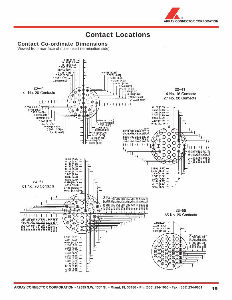
Contact Locations
Contact Co-ordinate DimensionsViewed from rear face of male insert (termination side)
ARRAY CONNECTOR CORPORATION • 12555 S.W. 130th St. • Miami, FL 33186 • Ph: (305) 234-1000 • Fax: (305) 234-6601 19
ARRAY CONNECTOR CORPORATION®
Contact LocationsContact Co-ordinate DimensionsViewed from rear face of male insert (termination side)

ARRAY CONNECTOR CORPORATION • 12555 S.W. 130th St. • Miami, FL 33186 • Ph: (305) 234-1000 • Fax: (305) 234-6601
www.arrayconnector.com C 2000 ARRAY CONNECTOR CORPORATION 1001 Printed in U.S.A.
Other Quality Connectors
QPL’d MIL-C-5015and Special Connectors
for Commercial Applications
Quick Disconnect ConnectorsSolder and Crimp Types
Rugged Acme Thread Connectorsfor Industrial Electrical Equipment
Distributed in U.S.A. by: Distributed in Europe by:
QPL’d MIL-C-26482 Series ISolder and Crimp Connectors
Special Cryogenic Connectors
Buffet/Galley ConnectorsSolder and Crimp Connectors