art 12
TRANSCRIPT
5/12/2018 Art 12 - slidepdf.com
http://slidepdf.com/reader/full/art-12-55a4d34218e0b 1/11
Advances in Bridge Engineering, March 24 - 25, 2006
433
PRESTRESSED CONCRETE BEAMS UNDER FATIGUE
LOADING
Suraj Parkash1, Ram Kumar
2and B. B. Sharma
3
1. Scientist, 2.HOD; Bridges & Structures Division, CRRI, New Delhi3. M.E. Student, AE, CPWD, New Delhi
ABSTRACT
Fatigue is a critical effect to consider in the design and evaluation of composite bridges such as RCC deck slab over prestressed concrete (PSC) girders. Fatigue may alsoendanger the durability of PSC bridges mainly due to fatigue in rebars and prestressingstrands. For most PSC highway bridges with short and medium span, traffic is the mostimportant action leading to fatigue. Most bridges in major cities experience large trafficvolume. For assessing the service life of prestressed concrete (PSC) bridges, thecomponent of a bridge such as beams/girders are subjected to repeated loads transferred
from the deck slab that normally covers live loads due to moving vehicles. The number of load cycles may be as low as a few hundreds cycles or as high as several million cycles.Fatigue failure can also occur in PSC structures in addition with other causes of deterioration. Very little research, however, has been done on experimental work of PSCstructures under fatigue loading. The present research work deals with the simulation of traffic live load on beam element and beams are subjected to cyclic loading. Theexperimental work has been carried out on the beams of 3.4 m span under simulated liveload till the crack appears. The beams have been tested for ultimate collapse load also.The experimental results of fatigue tests on bonded and unbonded beams shows thedevelopment of flexural cracks along the depth & near to mid span portion of the beamunder designed live load which provides information about the service span of a bridgeunder extreme loading case.
INTRODUCTION
A prestressed concrete structure has many advantages, such as delaying cracks,saving materials, reducing deflection, and has been widely or increasingly used in long-span structures [Lin and Burns (1982)]. In order to analyze these sophisticated andcomplex prestressed concrete structures accurately and efficiently, several nonlinear models for prestressed concrete structures have been proposed during the past decades[Nikolic and Mihanovic (1997)].
For bonded tendons, the deformation field of the tendon is the same as that of theconcrete on the interface. Therefore, the analysis from prestress transfer to whole loadinghistory, including relaxation of prestress, shrinkage and creep of concrete, can be carriedon directly with the combined stiffness of concrete, steel, and tendon. However, in the
case of unbonded tendons, including bonded post-tensioned structures in the prestressing
5/12/2018 Art 12 - slidepdf.com
http://slidepdf.com/reader/full/art-12-55a4d34218e0b 2/11
Suraj Parkash, Ram Kumar, B. B. Sharma
434
transfer stage, the deformation field of the tendon is not equal to that of concrete, exceptat the anchorages. In order to represent the interaction between the concrete and tendon,the contribution of the tendon is represented by equivalent nodal loads. In order to satisfythe displacement compatibility between concrete and tendon at the anchorage, complex
iterative procedures are needed due to the interactions between concrete and tendons, andamong multiple tendons.
Internal unbonded tendons are used widely in prestressing concrete structures.Flexural deformation of an unbonded prestressed member subjected to load, leads to anincrease in the stress level in the tendon. In a simply supported unbonded prestressedconcrete beam, subjected to a concentrated load at mid span, the strain induced in theconcrete at the level of the tendon due to this load, varies according to the bendingmoment diagram [Allouche (1996)]. Compatibility of deformation requires that thetendon elongate by an amount equal to the deformation in the concrete over the length of the tendon, resulting in an increase in the strain in the tendon. The strain increment, andaccompanying stress increment, will be uniform over the length of the tendon, assumingthat no friction exists between the tendon and its duct.
Determination of this stress increment is necessary to calculate the moment of resistance of a cross section in an unbonded member. The analytical and experimentalstudies have been conducted by Allouche,(1996) to identify factors that influence thisstress increment such as concrete compressive strength, amount of prestressedreinforcement, and the span to depth ratio.
The existing body of knowledge on the behavior of continuous beams and slabs, prestressed with unbonded tendons, is limited, with the result that the effects of parameters such as pattern of loading and amount of compression reinforcement at thesupport are not considered in the code equations.
Olson et al (1990), carried out experimental study of 4 PSC bridge girders after 20years in service and examined the performance of girders which were originally designedunder various fatigue loading levels (with no tension, allow tension up to 0.25√ f ck MPaand 0.50√ f ck MPa respectively). The girders were subjected to fatigue loading of various number of load cycles at different loading levels and plotted the load deflectioncurves at the end of each fatigue loadings. The loading begun with 0.5 Million cycles of decompression (that is , with no tension). After satisfactory performance through thisloading history, stress ranges were collected and the fatigue loading level was increasedto 0.25√ f ck MPa nominal tension. Once again the specimen survived 0.5 Million cyclesof loading. Stress ranges were collected and the loading increased to 0.50√ f ck MPanominal tension. After 0.282 Million cycles of loading, at this level a strand failed. Thefatigue loading was stopped and the specimen was tested statically to failure.

5/12/2018 Art 12 - slidepdf.com
http://slidepdf.com/reader/full/art-12-55a4d34218e0b 3/11
Advances in Bridge Engineering, March 24 - 25, 2006
435
OBJECTIVES OF PRESENT INVESTIGATION
The main objective of the present investigation is to study the development of cracking, ultimate moment carrying capacity and load-deflection response of post-tensioned bonded & unbonded beams in flexure. Except under special circumstances,
unbonded prestressed structures are not preferred generally, mainly because the steel isexposed in some structures and hence likely to be corroded. In other structures, even if the steel is inside the concrete it might still get corroded wherever micro-cracking occurs.The micro-cracks may be due to the shrinkage of concrete, occurrence of temperaturegradient from surface to the inside of the structure when the concrete is hardening anddue to exposure to an aggressive atmosphere to obtain bonded behavior throughgrouting.
DESIGN OF PRESTRESSED BEAM AND SUIMULATION OF LIVE LOAD:
The simply supported PSC beams are 3.4 m long, spanning 3.0 m between thecenters of supports as shown in Fig.1 (a). The beam had rectangular cross section havingsize 15cm x 30 cm, Fig.1 (b). The beam is designed for its dead load, super imposed dead
load and simulated live load. The two point load on each 1/3rd
span is evaluated bycalculating the equivalent bending moment due to simulated live load. The MS frame of Isection is designed to transfer single vertical load from actuator to two point load at therequired location.
Material Properties
Prestressing steel
Select 7 ply 12.7 mm nominal diameter of strand (Low relaxation class II strand,confirming to IS 14268:1995).The properties of 7 ply 12.7 mm diameter strand are asfollows:
a) Nominal area = 98.7 mm2
b) Ultimate tensile strength = 1860 MPa
c) Breaking Strength of Strand = 183.7 KN
d) Allowable prestressing force in strand cables at stressing end before Seating of anchorages (as per clause 8 of IRC: 18-2000) = 0.9*0.85*183.7 = 140 KN
e) Allowable tensile strength = 0.9*0.85*1860 = 1423 MPa
Grade of concrete
Mix of concrete for prestressed beam is taken M 45.

5/12/2018 Art 12 - slidepdf.com
http://slidepdf.com/reader/full/art-12-55a4d34218e0b 4/11
Suraj Parkash, Ram Kumar, B. B. Sharma
436
Fig. 1(a) Longitudinal Section of beam Fig. 1(b) Cross Section of
beam
Simulation of Live Load
Details of IRC live loadings
As per Appendix I of clause 207.1.1 of IRC:6-2000, select load class as 5R wheeled vehicle, four wheeler(Fig. 2). The maximum axle load is 2.2 ton . The equivalenttwo point load on 3.4 m span test beam is evaluated to simulate the maximum bendingmoment obtained from the Influence line diagram from Fig. 2.
Fig. 2 B.M. Influence line diagram at mid span due to Class 5R loading
3.0
3.4
0.15
0.30
1.0 1.01.0
0.5 0.5
0.2 0.2
0.15
0.61m 3.05m
2.1 t 3.4 t
0.91m
Strand
5/12/2018 Art 12 - slidepdf.com
http://slidepdf.com/reader/full/art-12-55a4d34218e0b 5/11
Advances in Bridge Engineering, March 24 - 25, 2006
437
The beam is checked for initial stage of prestressing, at service load condition,ultimate load stage as per the IRC codal provisons with the adequate consideration of prestress loss during the period between prestressing and testing of the beams. The proper parabolic profile lay out of strand was formed and placed the non-prestressed skeleton
reinforcement including main and shear steel. The beams are casted in the lab andcompaction of concrete was carried out be needle vibrator. Proper quality control wascarried out such as cube test, slump test etc.
EXPERIMENTAL PROGRAMME:
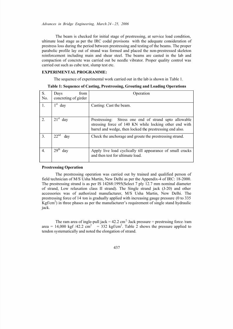
The sequence of experimental work carried out in the lab is shown in Table 1.
Table 1: Sequence of Casting, Prestressing, Grouting and Loading Operations
S. No.
Days fromconcreting of girder
Operation
1. 1st day Casting: Cast the beam.
2. 21st day Prestressing: Stress one end of strand upto allowablestressing force of 140 KN while locking other end with barrel and wedge, then locked the prestressing end also.
3. 22nd day Check the anchorage and groute the prestressing strand.
4. 29th day Apply live load cyclically till appearance of small cracksand then test for ultimate load.
Prestressing Operation
The prestressing operation was carried out by trained and qualified person of field technician of M/S Usha Martin, New Delhi as per the Appendix-4 of IRC: 18-2000.The prestressing strand is as per IS 14268:1995(Select 7 ply 12.7 mm nominal diameter of strand, Low relaxation class II strand). The Single strand jack (J-20) and other accessories was of authorized manufacturer, M/S Usha Martin, New Delhi. The prestressing force of 14 ton is gradually applied with increasing gauge pressure (0 to 335
Kgf/cm2) in three phases as per the manufacturer’s requirement of single stand hydraulic jack.
The ram area of ingle-pull jack = 42.2 cm2. Jack pressure = prestrssing force /ramarea = 14,000 kgf /42.2 cm2 = 332 kgf/cm2. Table 2 shows the pressure applied to
tendon systematically and noted the elongation of strand.
5/12/2018 Art 12 - slidepdf.com
http://slidepdf.com/reader/full/art-12-55a4d34218e0b 6/11
Suraj Parkash, Ram Kumar, B. B. Sharma
438
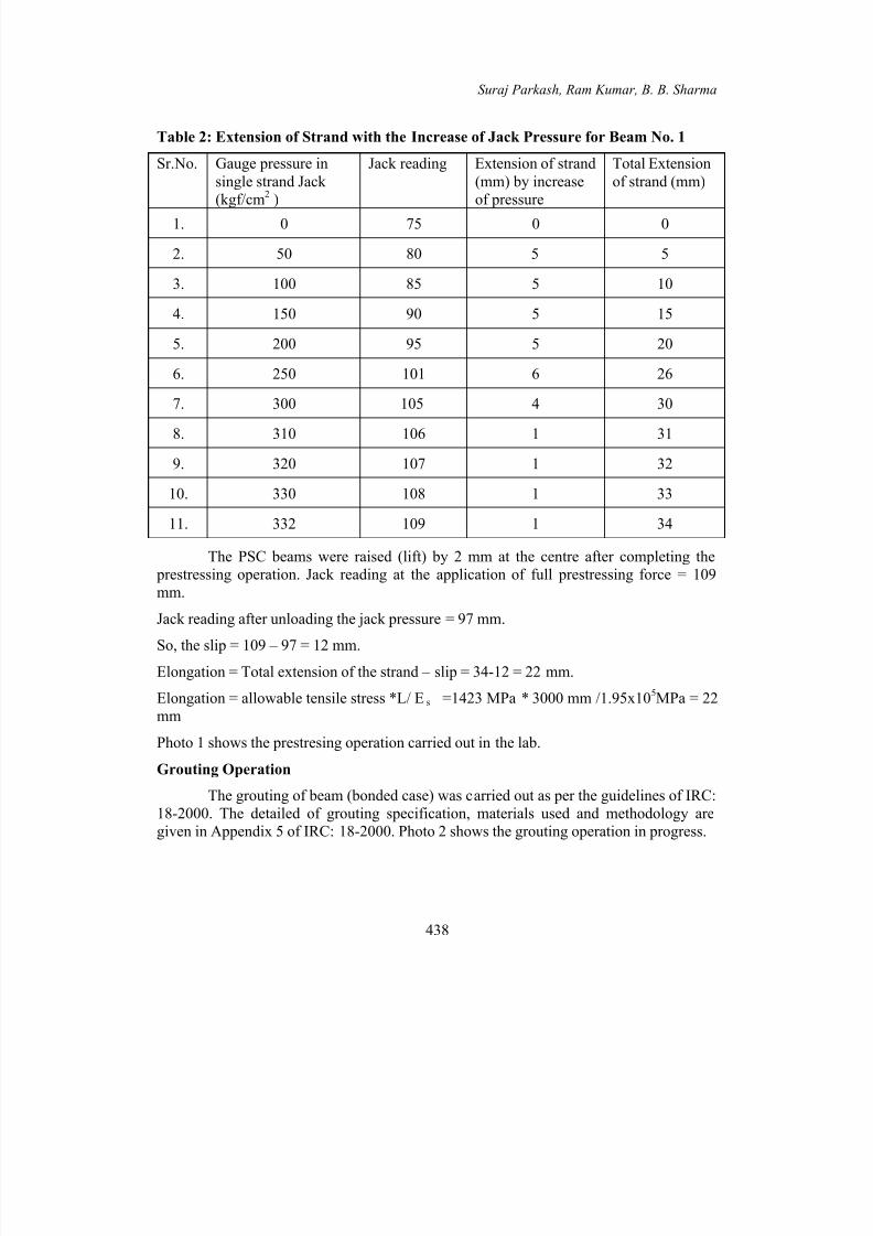
Table 2: Extension of Strand with the Increase of Jack Pressure for Beam No. 1
Sr.No. Gauge pressure insingle strand Jack (kgf/cm2 )
Jack reading Extension of strand(mm) by increaseof pressure
Total Extensionof strand (mm)
1. 0 75 0 0
2. 50 80 5 5
3. 100 85 5 10
4. 150 90 5 15
5. 200 95 5 20
6. 250 101 6 26
7. 300 105 4 30
8. 310 106 1 31
9. 320 107 1 32
10. 330 108 1 33
11. 332 109 1 34
The PSC beams were raised (lift) by 2 mm at the centre after completing the prestressing operation. Jack reading at the application of full prestressing force = 109mm.
Jack reading after unloading the jack pressure = 97 mm.
So, the slip = 109 – 97 = 12 mm.Elongation = Total extension of the strand – slip = 34-12 = 22 mm.
Elongation = allowable tensile stress *L/ Es =1423 MPa * 3000 mm /1.95x105MPa = 22mm
Photo 1 shows the prestresing operation carried out in the lab.
Grouting Operation
The grouting of beam (bonded case) was carried out as per the guidelines of IRC:18-2000. The detailed of grouting specification, materials used and methodology aregiven in Appendix 5 of IRC: 18-2000. Photo 2 shows the grouting operation in progress.

5/12/2018 Art 12 - slidepdf.com
http://slidepdf.com/reader/full/art-12-55a4d34218e0b 7/11
Advances in Bridge Engineering, March 24 - 25, 2006
439
Photo 1: Prestresing Operation in Progress Photo 2: Grouting Operation in
Progress
Testing of Beams under Fatigue and Ultimate Loading
The testing operation is focused on assessing the fatigue performance and
ultimate strength response of PSC beams. The results from the experimental testing program described herein are compared with that calculated by the equation in the IRC:18-2000.
Fatigue testing of beams
The bonded and unbonded beams are subjected to 2.2 ton cyclic loading of sinusoidal wave (Fig. 3) at centre of beam by single hydraulic actuator in such a waythat I section placed on top of beam distribute the load at two point load at each 1/3rd spanfrom the ends (Photo 3). The actuator operating at 5.56 cycles per second. Fig.3 showsthe pattern of applied actual cyclic loading (shown only up to 200 sec only) by thehydraulic actuator in the lab. After appearance of fine cracks and propagation or
widening of the cracks (Photo 4), the test has been carried out for ultimate load.
Ultimate load test of beams
After appearance of flexure cracks near the mid span, the beam is subjected tolinear static loading at the rate of loading of 0.1 kN/sec. Photo 5 shows the collapse of the beam at ultimate load of 110 kN. The real data obtained from the fatigue testing machineare plotted and Fig. 4 shows the mid span deflection (mm) with linearly increasingapplied vertical load (kN). It is observed from this graph that the ultimate collapse load of the beam is 110 kN and maximum mid span deflection is 37 mm.

5/12/2018 Art 12 - slidepdf.com
http://slidepdf.com/reader/full/art-12-55a4d34218e0b 8/11
Suraj Parkash, Ram Kumar, B. B. Sharma
440
0 20 40 60 80 100 120 140 160 180 2005
10
15
20Variation of cyclic load with time
A p p l i e d
L o a d ( k N )
Time(sec)
Fig. 3 Sinusoidal wave of 5.56 Hz Photo 3: A view of the PSC beam for
testing
DISCUSSION
The post-tensioned prestressed bonded beams were tested along with unbonded beamsfor fatigue & ultimate loading stage and the experimental results are presented in thisthesis. The beams are rectangular in cross-section of size 15cmx30 cm, simply supportedand loaded two pointy loads at one third span point from the ends. Development of cracking pattern, behavior beyond the service loads and load deflection response arestudied. The results of the ultimate/collapse load test are compared with those computedwith IRC codal guidelines.
Photo 4 Appearance & Propagation of Crack in the Beam During Fatigue Loading

5/12/2018 Art 12 - slidepdf.com
http://slidepdf.com/reader/full/art-12-55a4d34218e0b 9/11
Advances in Bridge Engineering, March 24 - 25, 2006
441
Photo 5 A View of Beam in Ultimate Stage Fig. 4 Variation of Deflection with
Load
SUMMARY
The beams of 3.4 m span are designed for dead load, superimposed load and
service live load simulated by class 5R loading as per IRC-18:2000. The casting,
prestressing and grouting operations were performed on the beams. The quality control of
the material such as cement, sand, the aggregates, mix designed, prestressing strand,
grouting of cement slurry etc, was carried out by various lab test and confirmed as per the
required standard. The Fatigue and Ultimate load test on the beams are carried out to
study the fatigue performance and ultimate collapse stage of PSC beams.
RESULTS
The test results of all the bonded and unbonded beams subjected to fatigue and
ultimate load tests are presented in Table 3. The comparative studies for bonded and
unbonded beams are carried out under cyclic loading and ultimate loading. The ultimate
load of the psc beam is valuated as per IRC 18-2000 and these predicted results are
compared with the experimental results.
0 5 10 15 20 25 30 35 40 0
20
40
60
80
100
120 Variation of mid-span deflection with applied load
Ap
pliedLoad(kN)
Mid-span deflection(mm)

5/12/2018 Art 12 - slidepdf.com
http://slidepdf.com/reader/full/art-12-55a4d34218e0b 10/11
Suraj Parkash, Ram Kumar, B. B. Sharma
442
Table 3: Comparison of Test Results of Bonded and Unbonded Prestressed Beams
S. No.
Beam Type Averagecrushingstrength
Nos. of cycles atwhich first
crack appear
Ultimatestaticload as
per labtest
Ultimateload as per IRC
18-2000
Deflectionat thecenter of
the beam atfirst crack
Deflectionat thecenter of
the beam atultimateload
1. Beam no.1Bonded
51.0MPa
0.5Million
110 kN 61 kN 1.00 mm 37 mm
2. Beam no.2Unbonded
52.0MPa
0.45Million
83 kN 61 kN 1.25 mm 33 mm
CONCLUSIONS
The deflection pattern for the bonded and unbonded prestressed beams tested proves the validity of theory that is defined as a maximum deflection of prestressedconcrete bridges upto the functionality limit is equal to span length/100.
• It is observed from the ultimate load test on the beams that the IRC code under stimates the ultimate load of the psc bemas.
• The experimental results of fatigue tests on bonded and unbonded beams showsthe development of flexural cracks along the depth & near to mid span portion of the beam under designed live load after a number of million cycles which provides information about the service span of a bridge under extreme loadingcase.
REFRENCES
1. Allouche, E.N., 1996. The Behaviour of Unbonded Partially PrestressContinuous Concrete Beams, M. Sc. Thesis, Queen’s Uni. , Kingston, Ontario,
Canada.2. IRC:5-1998 : Standard Specifications and Code of Practice for Road Bridges,
Section I, General Features of Design (7th Revision), Indian Road Congress.
3. IRC:6-2000 : Standard Specifications and Code of Practice for Road Bridges,Section II, Load and Stresses (4th Revision), Indian Road Congress.
4. IRC:18-2000 : Design Criteria for Prestressed Concrete Road Bridges (Post-tensioned Concrete), (3rd Revision), Indian Road Congres.
5. IRC:21-2000 : Standard Specifications and code of practice for Road Bridges,Section III, Cement Concrete (Plain and Reinforced ) (3rd Revision), Indian Road Congress.

5/12/2018 Art 12 - slidepdf.com
http://slidepdf.com/reader/full/art-12-55a4d34218e0b 11/11
Advances in Bridge Engineering, March 24 - 25, 2006
443
6. IRC:22-1986 : Standard Specifications and Code of Practice for Road Bridges,Section VI , Composite Construction (1st Revision), Indian Road Congress.
7. IS 14268:1995, Uncoated Stress Relieved Low Relaxation Seven-Ply Strand for Prestressed Concrete-Specification.
8. Lin, T.Y. and NED H. BURNS, 1982. Design of Prestressed Concrete Structures, John Wiley & Sons.
9. Nikolic Z. and Mihanovic, A., 1997. Non-Linear Finite Element Analysis of Post- Tensioned Concrete Structures, J. of Engineering Computations, Vol. 4, No. 5, pp. 509-528.
10. Olson, S.A., French, C.W. and Leon, R.T., 1990. Prestress Concrete Girders after 20 Years in Service, Bridge Evaluation, Repair and Rehabilitation by A.S.
Nowak , Kluwer Academic Publishers, Netherland, pp. 391-403.