arthrex continuous wave iii arthroscopy pump user’s … infusi… · · 2013-02-11operation of...
TRANSCRIPT
Continuous Wave III Arthroscopy Pump
User’s Guide The Arthrex Continuous Wave III Arthroscopy Pump User’s
Guide provides important information for the safe operation of all components of the Arthrex Continuous Wave III Arthroscopy Pump (Model AR-6475), including accessories. Read this User’s Guide thoroughly prior to using this system and keep it in an easily accessible place for use by all operating personnel. Read and follow all safety warnings, cautions, and precautions.
U.S. Patent No. 5,520,638
Arthrex, Inc.
Naples, FL 34108-1945 USA
Toll Free: +1 800 934-4404
www.arthrex.com
Arthrex Med. Inst. GmbH
85757 Karlsfeld, Germany
Telephone: +1 49 81 31 59 57 290
www.arthrex.de
LM0620B
© Arthrex, Inc. All rights reserved.
AR
-6475 G
B
Continuous Wave III Arthroscopy Pump User’s Guide
2
GB
TABLE OF CONTENTS
1.0 Read This First! 5
1.1 Important Symbols and Conventions 5
1.2 Shipping, Unpacking, and Warranty Information 5
1.3 Important Safety Information 6
2.0 Product Description 6
2.1 Functional Description and Intended Use 6
2.2 Product Features 7
2.2.1 Console: Front Panel 7
2.2.2 Console: Rear Panel 8
2.2.3 Vacuum Fluorescent Display (VFD): Status and Error Messages 9
2.2.4 Measured Pressure Bar Graph 11
2.2.5 Tubing: Configurations 12
2.2.6 Tubing: Main Pump Tubing Set 14
2.2.7 Tubing: Extension Tubing System 14
2.2.8 Tubing: ReDeuce™ Pump Tubing 14
2.2.9 Tubing: ReDeuce™ Patient Tubing 14
2.2.10 Tubing: Y-Adapter Tubing 14
2.2.11 Remote Control Unit (AR-6476) 14
2.3 Technical Specifications 16
3.0 Setup 17
3.1 AC Power Safety Considerations 17
3.2 How to Determine if the AR-6475 is Causing Interference to Other Devices 18
3.3 Basic Setup Procedure for the AR-6475 18
3.4 How to Set Up the Pump Tubing 19
3.5 How to Set Up the Two-Piece Tubing System 19
3.6 How to Change the Brightness of the VFD Display 20
3.6.1 Pumps without a Rear Access Panel 20
3.6.2 Pumps with a Rear Access Panel 20
3.7 How to Change the Language Setting 21
3.7.1 Pumps without a Rear Access Panel 21
3.7.2 Pumps with a Rear Access Panel 21
3.8 How to Test the Power Supply Voltages and VFD 22
3
GB
Adapteur Power System User’s Guide
3.9 How to Verify Safe Setup and Performance before Use 22
3.9.1 Pressure Reading on the Display 22
3.9.2 Pressure Verification Procedure for the AR-6475 Arthroscopy Pump 23
3.9.3 Abnormal Operation 24
3.9.4 Overpressure Sensing 25
3.9.5 Roller Housing 25
3.9.6 Tubing Sensor Coupler 25
4.0 Operation 26
4.1 Initial Pressure Settings 26
4.2 How to Operate the AR-6475 in Normal Mode 27
4.3 How to Operate the AR-6475 in FLUSH Mode 28
5.0 Cleaning and Sterilization 28
5.1 Console (AR-6475) 28
5.2 Remote Control (AR-6476) 28
5.3 Tubing 28
6.0 Maintenance 30
7.0 Technical Support 30
7.1 How to Display the Software Version 30
8.0 Troubleshooting 31
9.0 Repair Policy 32
10.0 Contact Information 32
10.1 Compliance Information 32
10.2 Related Documents 32
Appendix A: Block Diagrams for AR-6475 without a Rear Access Panel 33
Appendix B: Block Diagrams for AR-6475 with a Rear Access Panel 43
Adapteur Power System User’s Guide
4
GB
List of Figures
Figure 1 Front Panel of Console 7
Figure 2 Rear Panel of Console (Without Access Panel) 9
Figure 3 Rear Panel of Console (With Access Panel) 9
Figure 4 Main Pump Tubing Configuration 12
Figure 5 ReDeuce™ Tubing Configuration 13
Figure 6 Remote Control (AR-6476) 15
List of Tables
Table 1 Front Panel Elements 8
Table 2 Rear Panel Elements 9
Table 3 Vacuum Fluorescent Display Messages 10
Table 4 Measured Pressure (±5%) Readings in Bar Graph 11
Table 5 Elements of the Main Pump Tubing Configuration 12
Table 6 Elements of the ReDeuce™ Tubing Configuration 13
Table 7 Remote Control Elements (AR-6476) 15
Table 8 Control Unit (AR-6475) Specifications 16
Table 9 Ambient conditions for operation 16
Table 10 Ambient conditions for storage (in shipping packaging) 16
Table 11 Remote Control (AR-6476) Specifications 16
Table 12 Initial Pressure Settings 26
Table 13 Common Problems and Remedies 31
1.0 Read This First!
1.1 Important Symbols and Conventions
The Continuous Wave III Arthroscopy Pump User’s Guide identifies critical, important, and useful information using these symbols and conventions. Your familiarity with these symbols and conventions is required.
W A R N I N G !The WARNING! symbol identifies critical information that must be followed precisely to avoid injury or death. The WARNING! symbol is the most important safety symbol.
The CAUTION! symbol identifies important methods and procedures that must be followed to avoid damaging the device or causing it to malfunction.
NOTE: This symbol identifies useful information that can simplify the setup
and operation of this device.
[x] Square brackets that enclose a letter, a number, or a lower-case roman numeral reference a callout on a line drawing. Section 2.2, Product Features, includes line drawings of all products associated with the AR-6475. Each line drawing has its own callout system to identify important elements of each product.
1.2 Shipping, Unpacking, and Warranty Information
Prior to use in a surgical procedure, carefully unpack and inspect the components for any sign of damage that may have occurred during shipping. If shipping damage is suspected, notify Arthrex or any authorized Arthrex distributor immediately. Any such damage could compromise patient safety.
If shipping or first-installation damage is not reported within seven business days of receiving the device, the warranty could be rendered void. Refer also to our General Terms of Business.
Arthrex assumes a warranty to the first purchaser for a twelve month period with regard to defects or failure of its medical devices. All defective products covered by the warranty are repaired or replaced free of charge by Arthrex at their discretion. The warranty does not cover any damage caused by unlawful use or improper handling of a product.
The warranty becomes invalid when Arthrex products are changed in any way or repairs are performed by any party other than Arthrex.
5
GB
Adapteur Power System User’s Guide
Arthrex will answer any questions referring to the quality, reliability and/or shelf life of any product identified in this User’s Guide.
1.3 Important Safety Information
W A R N I N G !This device is to be used only under the supervision of a trained and licensed physician. This device should not be used by untrained personnel or used for indications other than those described in this User’s Guide.
U.S. Federal Law restricts this device to use only by or on order of a physician.
DO NOT—under any conditions or for any reason—remove the cover of the AR-6475.
NOTE: Read this User’s Guide thoroughly before attempting to operate the
device and retain for future reference.
Users of this device are encouraged to contact their Arthrex representatives if, in their professional judgment, they require a more comprehensive surgical technique.
2.0 Product Description
2.1 Functional Description and Intended Use
The Arthrex AR-6475 Continuous Wave III Arthroscopy Pump is a safe, reliable, user-friendly system that maintains constant, non-pulsed control of intraarticular rinsing and distention pressure throughout all phases of an arthroscopic surgical procedure.
The AR-6475 includes:
A universal input-grade switching power supply that allows the pump to function automatically at voltage ranges found worldwide;
Improved displays that combine vacuum fluorescent and dot matrix displays for high contrast and visibility;
A reprogrammable microcontroller with upgradeable software that supports multilingual messaging;
Membrane switch overlays for user inputs and easier cleaning; and,
A FLUSH function for providing elevated pressure to stop bleeding and flow rate to clear joint spaces quickly.
Continuous Wave III Arthroscopy Pump User’s Guide
6
GB
The AR-6475 is intended to provide continuous pulse-free flow that reacts immediately to changes in the intraarticular pressure so that joint distention can be sustained even under high shaver extraction volumes or secondary outflow. The user-defined settings for pressure and flow are adjustable through controls located on the console front panel or on the remote control.
There are three pump tubing options for the AR-6475:
1. Main Pump Tubing Set only. This tubing, when used alone, must be replaced after each patient.
2. Main Pump Tubing Set and Extension Tubing combination. The Main Pump Tubing Set can be reused for an entire surgical day, while the Extension Tubing must be replaced after each patient.
3. ReDeuce™ Pump Tubing and ReDeuce™ Patient Tubing combination.The ReDeuce™ Pump Tubing can be reused for an entire surgical day, while the ReDeuce™ Patient Tubing must be replaced after each surgical procedure. The ReDeuce™ system offers a higher flow rate than the Main Pump Tubing Set/Extension Tubing combination.
The optional Y-Tubing connects up to four irrigation bags and can be used with all AR-6475 pump tubing options.
2.2 Product Features
2.2.1 Console: Front Panel
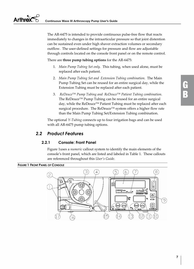
Figure 1uses a numeric callout system to identify the main elements of the console’s front panel, which are listed and labeled in Table 1. These callouts are referenced throughout this User’s Guide.
FIGURE 1 FRONT PANEL OF CONSOLE
7
GB
Continuous Wave III Arthroscopy Pump User’s Guide
TABLE 1 FRONT PANEL ELEMENTS
ELEMENT NUMBER
ELEMENT NAME
1 Tubing IN Guide (beneath the Green dot)/ Tubing OUT Guide 2 Green dot (for orienting the Pump Tubing) 3 Roller assembly 4 Roller housing door 5 Type “BF” shock hazard symbol 6 Vacuum Fluorescent Display (VFD) 7 Measured pressure bar graph 8 AC mains power toggle switch 9 Activate/Deactivate FLUSH function button
10 Pump motor Enable/Disable button 11 Flow rate in percent 12 Flow buttons and symbol. Increase or decrease maximum fluid
flow rate to the joint space by ten percent on a scale of ten to 100 percent.
13 Target distention pressure in mmHg 14 Pressure Set buttons and symbol. Increase or decrease target
pressure in the joint space by one mmHg on a scale of zero to 120 mmHg.
15 Locking lever for roller housing door 16 Tubing sensor indicator LED. A steady green LED indicates
that the tubing is connected properly. A flashing red LED indicates that the tubing is not present or that it is connected incorrectly.
17 Tubing sensor coupler
2.2.2 Console: Rear Panel
Figure 2 and 3 use an alphabetic callout system to identify the main elements of the console’s rear panel for both new and old pump versions. These callouts are also listed and labeled in Table 2 and referenced throughout this User’s Guide.
Continuous Wave III Arthroscopy Pump User’s Guide
8
GB
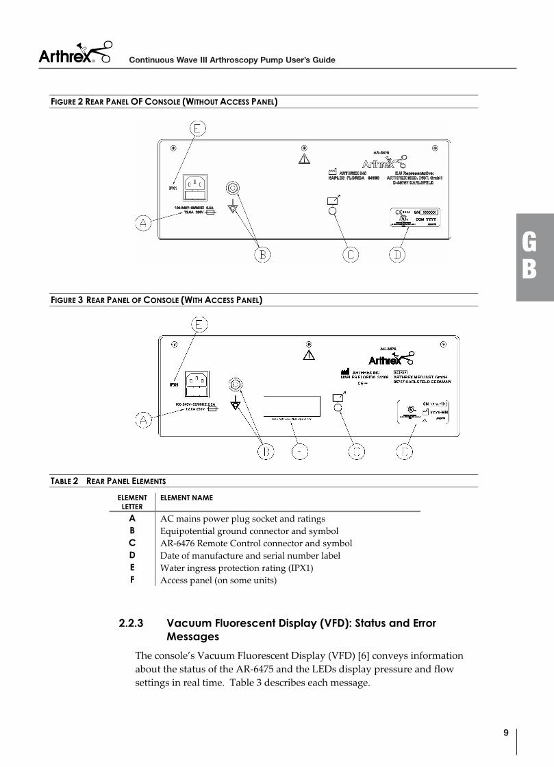
FIGURE 2 REAR PANEL OF CONSOLE (WITHOUT ACCESS PANEL)
FIGURE 3 REAR PANEL OF CONSOLE (WITH ACCESS PANEL)
TABLE 2 REAR PANEL ELEMENTS
ELEMENT LETTER
ELEMENT NAME
A AC mains power plug socket and ratings B Equipotential ground connector and symbol C AR-6476 Remote Control connector and symbol D Date of manufacture and serial number label E Water ingress protection rating (IPX1) F Access panel (on some units)
2.2.3 Vacuum Fluorescent Display (VFD): Status and Error Messages
The console’s Vacuum Fluorescent Display (VFD) [6] conveys information about the status of the AR-6475 and the LEDs display pressure and flow settings in real time. Table 3 describes each message.
9
GB
Continuous Wave III Arthroscopy Pump User’s Guide
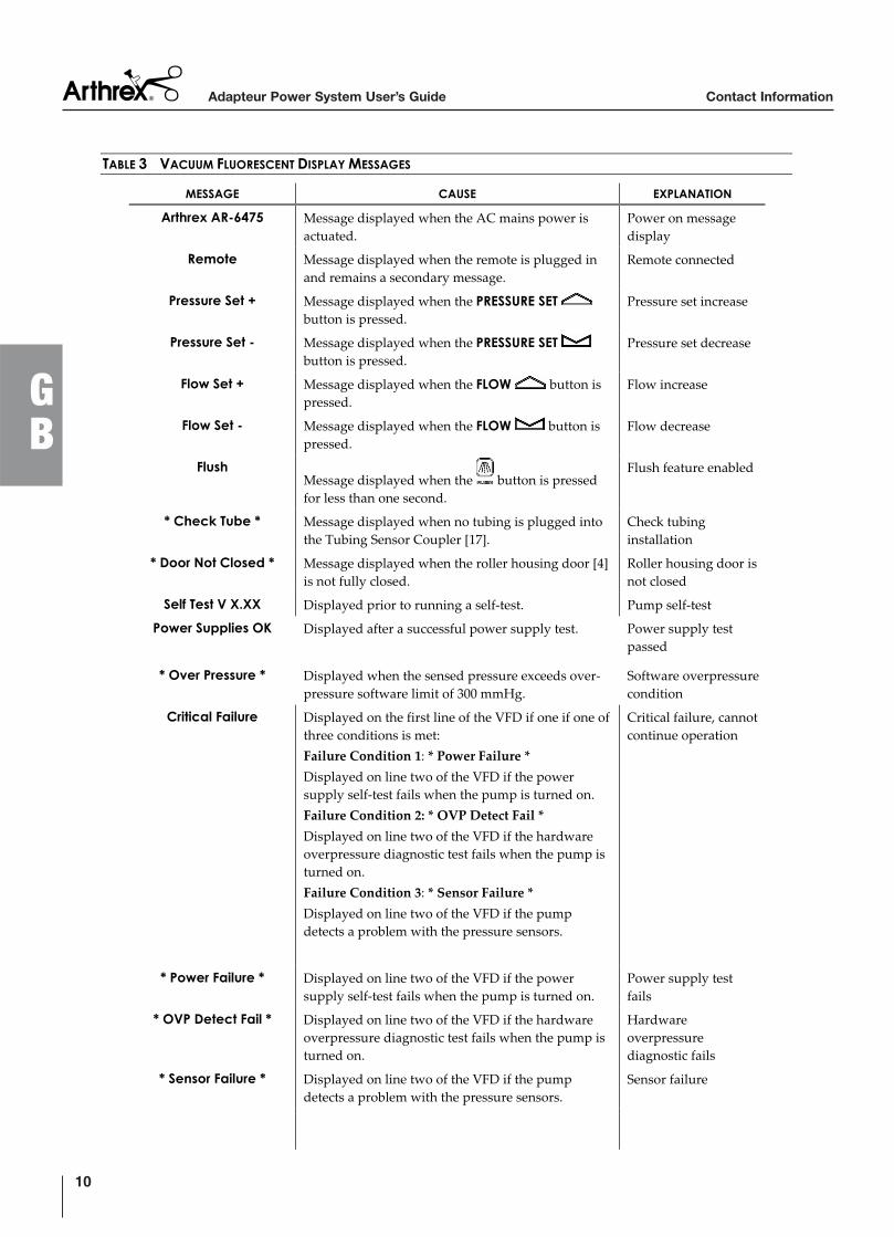
TABLE 3 VACUUM FLUORESCENT DISPLAY MESSAGES
MESSAGE CAUSE EXPLANATION
Arthrex AR-6475 Message displayed when the AC mains power is actuated.
Power on message display
Remote Message displayed when the remote is plugged in and remains a secondary message.
Remote connected
Pressure Set + Message displayed when the PRESSURE SETbutton is pressed.
Pressure set increase
Pressure Set - Message displayed when the PRESSURE SETbutton is pressed.
Pressure set decrease
Flow Set + Message displayed when the FLOW button is pressed.
Flow increase
Flow Set - Message displayed when the FLOW button is pressed.
Flow decrease
FlushMessage displayed when the button is pressed for less than one second.
Flush feature enabled
* Check Tube * Message displayed when no tubing is plugged into the Tubing Sensor Coupler [17].
Check tubing installation
* Door Not Closed * Message displayed when the roller housing door [4] is not fully closed.
Roller housing door is not closed
Self Test V X.XX Displayed prior to running a self-test. Pump self-test
Power Supplies OK Displayed after a successful power supply test. Power supply test passed
* Over Pressure * Displayed when the sensed pressure exceeds over-pressure software limit of 300 mmHg.
Software overpressure condition
Critical Failure Displayed on the first line of the VFD if one if one of three conditions is met:
Failure Condition 1: * Power Failure *
Displayed on line two of the VFD if the power supply self-test fails when the pump is turned on.
Failure Condition 2: * OVP Detect Fail *
Displayed on line two of the VFD if the hardware overpressure diagnostic test fails when the pump is turned on.
Failure Condition 3: * Sensor Failure *
Displayed on line two of the VFD if the pump detects a problem with the pressure sensors.
Critical failure, cannot continue operation
* Power Failure * Displayed on line two of the VFD if the power supply self-test fails when the pump is turned on.
Power supply test fails
* OVP Detect Fail * Displayed on line two of the VFD if the hardware overpressure diagnostic test fails when the pump is turned on.
Hardwareoverpressurediagnostic fails
* Sensor Failure * Displayed on line two of the VFD if the pump detects a problem with the pressure sensors.
Sensor failure
Adapteur Power System User’s Guide Contact Information
10
GB
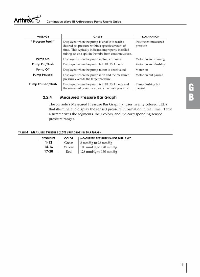
MESSAGE CAUSE EXPLANATION
* Pressure Fault * Displayed when the pump is unable to reach a desired set pressure within a specific amount of time. This typically indicates improperly installed tubing set or a split in the tube from continuous use.
Insufficient measured pressure
Pump On Displayed when the pump motor is running. Motor on and running
Pump On/Flush Displayed when the pump is in FLUSH mode. Motor on and flushing
Pump Off Displayed when the pump motor is deactivated. Motor off
Pump Paused Displayed when the pump is on and the measured pressure exceeds the target pressure.
Motor on but paused
Pump Paused/Flush Displayed when the pump is in FLUSH mode and the measured pressure exceeds the flush pressure.
Pump flushing but paused
2.2.4 Measured Pressure Bar Graph
The console’s Measured Pressure Bar Graph [7] uses twenty colored LEDs that illuminate to display the sensed pressure information in real time. Table 4 summarizes the segments, their colors, and the corresponding sensed pressure ranges.
TABLE 4 MEASURED PRESSURE (±5%) READINGS IN BAR GRAPH
SEGMENTS COLOR MEASUERED PRESSURE RANGE DISPLAYED
1-13 Green 8 mmHg to 98 mmHg 14-16 Yellow 105 mmHg to 120 mmHg 17-20 Red 128 mmHg to 150 mmHg
11
GB
Continuous Wave III Arthroscopy Pump User’s Guide
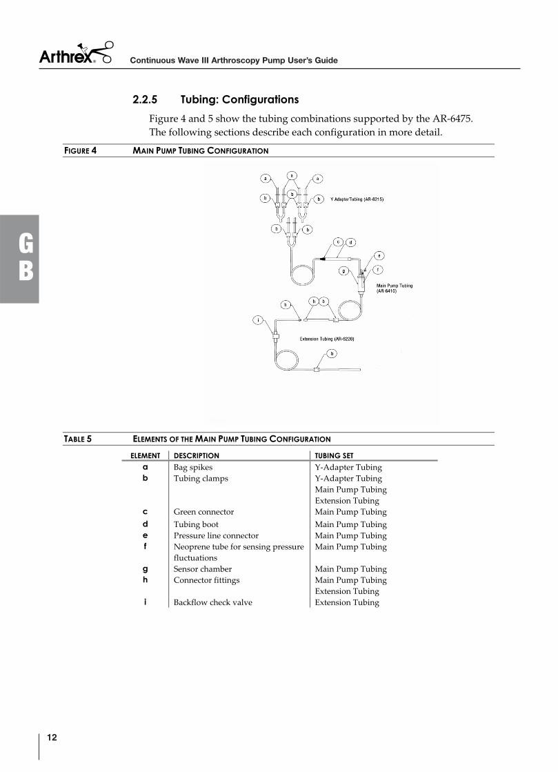
2.2.5 Tubing: Configurations
Figure 4 and 5 show the tubing combinations supported by the AR-6475. The following sections describe each configuration in more detail.
FIGURE 4 MAIN PUMP TUBING CONFIGURATION
TABLE 5 ELEMENTS OF THE MAIN PUMP TUBING CONFIGURATION
ELEMENT DESCRIPTION TUBING SET
a Bag spikes Y-Adapter Tubing b Tubing clamps Y-Adapter Tubing
Main Pump Tubing Extension Tubing
c Green connector Main Pump Tubing
d Tubing boot Main Pump Tubing e Pressure line connector Main Pump Tubing f Neoprene tube for sensing pressure
fluctuationsMain Pump Tubing
g Sensor chamber Main Pump Tubing h Connector fittings Main Pump Tubing
Extension Tubing i Backflow check valve Extension Tubing
Continuous Wave III Arthroscopy Pump User’s Guide
12
GB
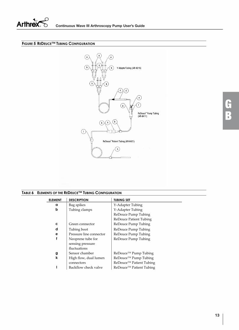
FIGURE 5 REDEUCE™ TUBING CONFIGURATION
TABLE 6 ELEMENTS OF THE REDEUCE™ TUBING CONFIGURATION
ELEMENT DESCRIPTION TUBING SET
a Bag spikes Y-Adapter Tubing b Tubing clamps Y-Adapter Tubing
ReDeuce Pump TubingReDeuce Patient Tubing
c Green connector ReDeuce Pump Tubing
d Tubing boot ReDeuce Pump Tubing e Pressure line connector ReDeuce Pump Tubing f Neoprene tube for
sensing pressure fluctuations
ReDeuce Pump Tubing
g Sensor chamber ReDeuce™ Pump Tubing k High flow, dual lumen
connectorsReDeuce™ Pump Tubing ReDeuce™ Patient Tubing
l Backflow check valve ReDeuce™ Patient Tubing
13
GB
Continuous Wave III Arthroscopy Pump User’s Guide
2.2.6 Tubing: Main Pump Tubing Set
The Main Pump Tubing Set offers inflow/pressure measurement tubing that, if used alone, must be completely discarded following each surgical procedure.It has the following components in each set: bag spikes, drip chamber, flexible boot for pump rollers, and a Luer connector for a scope sheath or other inflow. The Main Pump Tubing is 13 feet (4.0 meters) in length.
NOTE: This User’s Guide assumes that you are using either the Main Pump
Tubing alone or in combination with the Extension Tubing, below.
Refer to the Directions for Use that accompany each tubing set for
specific information or contact your Arthrex representative.
2.2.7 Tubing: Extension Tubing System
The unique Extension Tubing System provides the economical option of using the Main Pump Tubing Set for an entire surgical day and replacing only the Extension Tubing Set after each individual surgery. The backflow check valve built into the Extension Tubing System prevents fluid backflow into the Main Pump Tubing, maintaining a closed sterile fluid environment during tubing replacements. The Extension Tubing is 8.5 feet (2.6 meters) in length.
2.2.8 Tubing: ReDeuce™ Pump Tubing
The ReDeuce™ Pump Tubing provides an alternative to complete replacement of the irrigation tubing after each patient. The backflow check valve of the ReDeuce™ Patient Tubing prevents contaminated fluid from reaching the ReDeuce™ Pump Tubing and permits its use for the entire surgical day. The ReDeuce™ Pump Tubing must be used with the ReDeuce™ Patient Tubing.
2.2.9 Tubing: ReDeuce™ Patient Tubing
The ReDeuce™ Patient Tubing must be used in the first arthroscopic procedure of the surgical day and replaced for each subsequent surgical procedure. It is used in conjunction with the ReDeuce™ Pump Tubing.
2.2.10 Tubing: Y-Adapter Tubing
The optional Y-Adapter Tubing can connect up to four irrigation bags. It can be used with either the Main Pump Tubing/Extension Tubing combination or the ReDeuce™ Pump Tubing/ReDeuce™ Patient Tubing combination.
2.2.11 Remote Control Unit (AR-6476)
The AR-6475 Continuous Wave III Arthroscopy Pump can be remotely controlled with the optional, autoclavable Remote Control (AR-6476). It provides the same controls present on the front panel of the pump, including flow rate and pressure adjustments, a FLUSH function, and the ability to activate/deactivate the pump motor. The remote control is 9.8 feet (3 meters) in length.
Continuous Wave III Arthroscopy Pump User’s Guide
14
GB

Do not disconnect the plug of the remote control by pulling on the cable. Remove the remote control plug by grasping and pulling on the body of the connector.
Figure 6 uses a lowercase roman numeral callout system to identify the main elements on the remote control, which are listed and labeled in Table 7. These callouts are referenced throughout this User’s Guide.
FIGURE 6 REMOTE CONTROL (AR-6476)
TABLE 7 REMOTE CONTROL ELEMENTS (AR-6476)
ELEMENT NUMERAL
ELEMENT NAME
i Flow buttons and symbol. Increase or decrease maximum fluid flow rate to the joint space by ten percent on a scale of ten to 100 percent.
ii Pressure Set buttons and symbol. Increase or decrease target pressure in the joint space by one mmHg on a scale of zero to 120 mmHg.
iii Activate/Deactivate FLUSH function iv Pump motor Enable/Disable switch v Lemo connector to attach to the corresponding plug on the rear
panel of the AR-6475.
15
GB
Continuous Wave III Arthroscopy Pump User’s Guide
2.3 Technical Specifications
TABLE 8 CONTROL UNIT (AR-6475) SPECIFICATIONS
Width 14.5 inches (36.5 cm) Height 5.0 inches (12.5 cm) Depth 12 inches (30 cm)
Weight 18 pounds (8.2 kg) Maximum Flow
rate1500 ml/minute minimum Measured in percent with a range of 10-100 percent in increments of 10 percent. Default flow rate at power-up is 100 percent
Pressure 0 - 120 mmHg Measured in mmHg in increments of 1 mmHg. Default pressure set at power-up is 0 mmHg
Overpressurecontrol
300mmHg
Pressure control Continuous pressure checking Operating mode PermanentWater protection IPX1
Main cable 10 A/250 V Connector CEE 7/7
Jack IEC 320/C13 Power supply 100-240 V, 50/60 Hz, 2A
Fuse T2.0A 250V Cleaning Surface cleaning with mild detergent
Sterilization Surface disinfection with mild disinfectant
TABLE 9 AMBIENT CONDITIONS FOR OPERATION
Temperature 50° to 104°F (10° to 40°C) Relative Humidity 0% to 100%, non-condensing
Air pressure 10.15 PSI (700 hPa) to 15.37 PSI (1060 hPa)
TABLE 10 AMBIENT CONDITIONS FOR STORAGE (IN SHIPPING PACKAGING)
Temperature -40° to 158°F (-40° to +70°C) Relative Humidity 0% to 100%, non-condensing
TABLE 11 REMOTE CONTROL (AR-6476) SPECIFICATIONS
Width 2.5 inches (63.5 mm) Height 3.8 inches (95.3 mm) Depth 0.9 inches (22.2 mm )
Weight 0.5 lbs. (0.23 kg) Cable length 9.8 feet (3 m )
Cleaning Surface cleaning with mild detergent Sterilization Autoclave
Continuous Wave III Arthroscopy Pump User’s Guide
16
GB
3.0 Setup
Users of this device are encouraged to contact their Arthrex representatives if, in their professional judgment, they require a more comprehensive surgical technique.
3.1 AC Power Safety Considerations
The AR-6475 is powered by a medically rated universal AC input switching power supply, which allows the console to be connected to any local AC mains outlet provided that you use the appropriate plug and a reliable ground conductor.
Two power cords are supplied by default with the AR-6475: one for the electrical standards of the U.S. and one for the electrical standards of Germany. Contact your Arthrex representative if you need a power cord that must meet the electrical standards of another country.
NOTE: Extension cords must meet local electrical standards.
The console has been designed to meet power-saving guidelines. The console has an AC mains switch on the front panel [8]. When the AC mains switch is OFF, no electrical power is drawn by the console.
When the AC mains switch is ON, the console automatically executes a brief series of self-diagnostic tests. Upon successful completion of these tests, the console displays on the VFD [6] the name and model number, Arthrex AR-6475. If the tests discover a problem, an error message will be displayed on the VFD. Refer to Table 3 for a complete list of VFD Messages.
In the event of an AC power interruption, the console can run continuously without fault for up to 10 milliseconds. If an AC power failure lasts longer than 10 milliseconds, the system will reset to default settings when AC power is restored.
W A R N I N G !If high-frequency devices are in use, or defibrillation of the patient is required, ensure that the device is not in direct contact with the patient.
17
GB
Continuous Wave III Arthroscopy Pump User’s Guide
3.2 How to Determine if the AR-6475 is Causing Interference to Other Devices
This device has passed testing for EMI / RFI radiation and susceptibility and EMC compatibility. However, if not set up and used in accordance with the instructions provided by Arthrex, this device may cause interference to other devices in the vicinity.
1. Power OFF the AC mains power switch [8] and then ON again. Try to correct the interference by following one or more of these measures:
2. Reorient or relocate the receiving device.
3. Increase the separation between devices.
4. Connect the device to an outlet on a circuit different from that to which the other device(s) are connected.
5. Consult the manufacturer or field service technician for the receiving device for guidance.
3.3 Basic Setup Procedure for the AR-6475
NOTE: Section 4.0, Operation, explains how to use the pump.
1. Place the AR-6475 on a flat, dry surface, such as an arthroscopy equipment cart or a small instrument table.
2. Connect the female end of the power cord for the AR-6475 into the AC socket [A] and the male end to the facility AC mains supply. Turn on the AR-6475 [8].
3. Verify the status of the AR-6475 displayed in the VFD [6].
4. Connect the tubing in accordance with Section 3.4 or 3.5.
5. Close and lock the roller housing door [4, 15].
6. If applicable, attach the Remote Control [v, C].
7. Refer to Section 4.0, Operation, for specific information on how to operate the AR-6475, including pressure and flow settings.
8. Press the button [10] to activate the pump motor.
Continuous Wave III Arthroscopy Pump User’s Guide
18
GB
3.4 How to Set Up the Pump Tubing
NOTE: These instructions describe the procedure to set up the Main Pump
Tubing or the ReDeuceTM Pump Tubing.
1. Remove the orange cap from the Pump Tubing and insert the connector fitting [e] of the Pump Tubing into the Tubing Sensor Coupler [17]. This step must be completed first to ensure accurate pressure measurements.
2. Release the locking lever [15] for the roller housing door [4] and open the door completely. Allow the door to rest against the stop. The roller mechanism is now exposed.
3. Place the green-collared section of the Pump Tubing [c] into the Tubing IN Guide [1] indicated by the green dot [2].
4. Guide the tubing boot [d] over the rollers and insert the output side of the tubing boot into the Tubing OUT Guide [1].
NOTE: The Pump Tubing is connected properly when the green connector [c]
on the Main Pump Tubing is aligned with the green dot [2] on the
front panel of the console.
5. Close and lock the roller housing door.
NOTE: The roller housing locking device must seat securely. If the door is not
closed securely an internal safety switch prevents the AR-6475 from
operating.
6. Puncture the fluid bags with the spikes on the tubing. If only one fluid bag is being used, seal the second fluid line by closing the clamp nearest the unused spike.
3.5 How to Set Up the Two-Piece Tubing System
NOTE: These instructions describe the procedure to set up the Extension
Tubing or ReDeuceTM Patient Tubing.
W A R N I N G !
The Extension or Patient Tubing must be changed for each patient.
7. The surgical staff removes the sterile Extension or Patient Tubing from its sterile pack and hands the connector [h or k] for the Pump Tubing set to the circulating nurse.
8. The circulating nurse connects the two tubing systems together [h to h in Figure 4 or k to k in Figure 5].
19
GB
Continuous Wave III Arthroscopy Pump User’s Guide
9. Attach the sterile connector cap (supplied with each Extension or Patient Tubing set) to the patient-end of the Pump Tubing.
NOTE: Following each surgery, detach and discard the Extension or Patient
Tubing Set.
W A R N I N G !
The sterile connector cap must be used to cover the Pump Tubing Set connector after each surgical procedure. This maintains sterility of the Pump Tubing and assures its safe operation throughout the entire surgical day.
3.6 How to Change the Brightness of the VFD Display
The VFD supports four levels of brightness. The brightest setting is 1, which is the default. The dimmest setting is 4. To change the brightness of the VFD display, follow these instructions.
3.6.1 Pumps without a Rear Access Panel
1. Power OFF the AC mains power switch [8] on the AR-6475.
2. Press and hold—simultaneously—the PRESSURE SET [14] and FLOW [12] buttons while powering ON the AC mains power switch [8]. The
following message will appear on the console’s VFD display [6]:
Prog Mode: BRIGHTNESS 1
3. Press the FLOW [12] or FLOW buttons to cycle through the brightness settings. Repeat until the desired brightness setting appears on the console’s VFD display.
4. Press to set the brightness.
5. Power OFF the AR-6475.
6. Power ON the AR-6475. The new brightness setting is in use.
3.6.2 Pumps with a Rear Access Panel
1. Power OFF the AC mains power switch [8] on the AR-6475.
2. Press and hold the PRESSURE SET [14] button while powering ON the AC mains power switch [8]. The following message will appear on the console’s VFD display [6]:
ADJUST INTENSITY
Continuous Wave III Arthroscopy Pump User’s Guide
20
GB
3. Press the FLOW [12] or FLOW buttons to cycle through the brightness settings. Repeat until the desired brightness setting appears on the console’s VFD display.
4. Press to set the brightness.
5. Power OFF the AR-6475.
6. Power ON the AR-6475. The new brightness setting is in use.
3.7 How to Change the Language Setting
The AR-6475 supports English, French, German, Italian, and Spanish. The default language is English. To change the language setting for VFD messaging, follow these instructions.
3.7.1 Pumps without a Rear Access Panel
1. Power OFF the AC mains power switch [8] on the AR-6475.
2. Press and hold—simultaneously—the PRESSURE SET [14] and FLOW [12] buttons while powering ON the AC mains power switch [8]. The
following message will appear on the console’s VFD display [6]:
PROG MODE: BRIGHTNESS 1
3. Press and release the button [10] to bypass the Brightness Adjustment Mode and switch to the Language Adjustment Mode. The following message will appear on the console’s VFD display:
4. PROG MODE: LANGUAGE ENGLISH
1. Press the FLOW [12] or FLOW buttons to cycle through the language settings. Repeat until the desired language appears on the console’s VFD display.
2. Press to set the language.
3. Power OFF the AR-6475.
4. Power ON the AR-6475. The new language setting is in use.
3.7.2 Pumps with a Rear Access Panel
1. Power OFF the AC mains power switch [8] on the AR-6475.
2. Press and hold the PRESSURE SET [14] button while powering ON the AC mains power switch [8]. The current language will appear on the console’s VFD display [6]:
ENGLISH
21
GB
Continuous Wave III Arthroscopy Pump User’s Guide
3. Press the FLOW [12] or FLOW buttons to cycle through the language settings. Repeat until the desired language appears on the console’s VFD display.
4. Press to set the language.
5. Power OFF the AR-6475
6. Power ON the AR-6475. The new language setting is in use.
3.8 How to Test the Power Supply Voltages and VFD
1. Power OFF the AR-6475.
2. Press and hold the FLOW [12] button and powering ON the AC mains power switch [8]. The following message will appear on the console’s VFD display [6]:
Self Test Vx.x
Vx.x is the version of the firmware self test.
The self test is comprised of two parts. The first part tests the VFD displays by illuminating all of the pixels and then displaying a series of digits. The VFD must be visually inspected to verify that all characters are legible and of the same brightness.
The second test verifies that the power supply voltages are within tolerances and that the hardware overpressure protection circuit is running as a backup to the software protection. The following message will appear on the console’s VFD display after successful completion of the tests:
Power Supplies OK
3.9 How to Verify Safe Setup and Performance before Use
3.9.1 Pressure Reading on the Display
The pump runs as an open system in nearly all applications: inflow and outflows are open (the outflow on the sheath or the outflow over the optical and working portals).
Under this system, the 50 mmHg shown on the display corresponds to the actual pressure in the joint. If there is a fall in pressure, the pump increases pressure up to 50 mmHg and then stops.
In contrast is the case of the closed system (100% impermeable joint and no egress of water whatsoever via the portals; occurs, for example, at a pressure measurement at the end of the applied part. A dynamic pressure arises here which is increased by a factor of 2.2 (at a
Continuous Wave III Arthroscopy Pump User’s Guide
22
GB
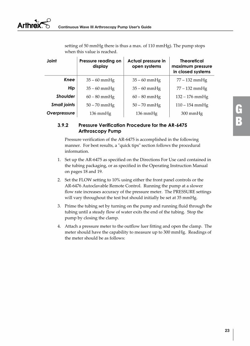
setting of 50 mmHg there is thus a max. of 110 mmHg). The pump stops when this value is reached.
Joint Pressure reading on display
Actual pressure in open systems
Theoreticalmaximum pressure in closed systems
Knee 35 – 60 mmHg 35 – 60 mmHg 77 – 132 mmHg
Hip 35 – 60 mmHg 35 – 60 mmHg 77 – 132 mmHg
Shoulder 60 – 80 mmHg 60 – 80 mmHg 132 – 176 mmHg
Small joints 50 – 70 mmHg 50 – 70 mmHg 110 – 154 mmHg
Overpressure 136 mmHg 136 mmHg 300 mmHg
3.9.2 Pressure Verification Procedure for the AR-6475 Arthroscopy Pump
Pressure verification of the AR-6475 is accomplished in the following manner. For best results, a "quick tips" section follows the procedural information.
1. Set up the AR-6475 as specified on the Directions For Use card contained in the tubing packaging, or as specified in the Operating Instruction Manual on pages 18 and 19.
2. Set the FLOW setting to 10% using either the front panel controls or the AR-6476 Autoclavable Remote Control. Running the pump at a slower flow rate increases accuracy of the pressure meter. The PRESSURE settings will vary throughout the test but should initially be set at 35 mmHg.
3. Prime the tubing set by turning on the pump and running fluid through the tubing until a steady flow of water exits the end of the tubing. Stop the pump by closing the clamp.
4. Attach a pressure meter to the outflow luer fitting and open the clamp. The meter should have the capability to measure up to 300 mmHg. Readings of the meter should be as follows:
23
GB
Continuous Wave III Arthroscopy Pump User’s Guide
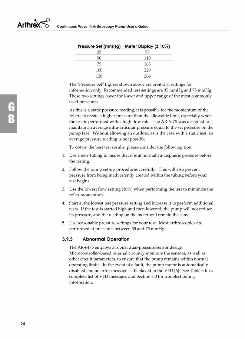
Pressure Set (mmHg) Meter Display (± 10%)35 77 50 110 75 165
100 220 120 264
The "Pressure Set" figures shown above are arbitrary settings for information only. Recommended test settings are 35 mmHg and 75 mmHg. These two settings cover the lower and upper range of the most commonly used pressures.
As this is a static pressure reading, it is possible for the momentum of the rollers to create a higher pressure than the allowable limit, especially when the test is performed with a high flow rate. The AR-6475 was designed to maintain an average intra-articular pressure equal to the set pressure on the pump face. Without allowing an outflow, as is the case with a static test, an average pressure reading is not possible.
To obtain the best test results, please consider the following tips:
1. Use a new tubing to insure that it is at normal atmospheric pressure before the testing.
2. Follow the pump set-up procedures carefully. This will also prevent pressure from being inadvertently created within the tubing before your test begins.
3. Use the lowest flow setting (10%) when performing the test to minimize the roller momentum.
4. Start at the lowest test pressure setting and increase it to perform additional tests. If the test is started high and then lowered, the pump will not reduce its pressure, and the reading on the meter will remain the same.
5. Use reasonable pressure settings for your test. Most arthroscopies are performed at pressures between 35 and 75 mmHg.
3.9.3 Abnormal Operation
The AR-6475 employs a robust dual-pressure sensor design. Microcontroller-based internal circuitry monitors the sensors, as well as other circuit parameters, to ensure that the pump remains within normal operating limits. In the event of a fault, the pump motor is automatically disabled and an error message is displayed in the VFD [6]. See Table 3 for a complete list of VFD messages and Section 8.0 for troubleshooting information.
Continuous Wave III Arthroscopy Pump User’s Guide
24
GB
NOTE: If abnormal console operation cannot be corrected, disinfect the pump,
re-package in the original shipping materials, and return to Arthrex,
accompanied by a brief description of the malfunction. Prior to
shipment, it is necessary to obtain a Return Authorization Number
from Arthrex.
3.9.4 Overpressure Sensing
The sensing circuitry in the AR-6475 measures the pressure of the fluid in the tubing. The overpressure alarm can be activated when the flow is abruptly interrupted or the joint is suddenly positioned in a way which reduces the joint capsule volume (e.g., bending the knee joint to the “Figure 4” position).
If an overpressure event occurs (300 mmHg within tubing and joint), a warning message reading *Over Pressure* will flash on the VFD and an audible alarm will sound. The pump motor is automatically disabled until the pressure returns to the set range.
To reduce the pressure in a joint, open an outflow and/or manipulate the joint to a stress-free position.
3.9.5 Roller Housing
The pump motor automatically deactivates when the roller housing door is opened. A locking mechanism prevents access to the rotating parts while the device is operating.
3.9.6 Tubing Sensor Coupler
The pump motor automatically deactivates when the tubing is disconnected from the pump. If the tubing is disconnected during a case it must be replaced by new tubing. Do not reconnect the tubing to the pump as it could lead to unreliable pressure measurements.
W A R N I N G !
If the tubing is disconnected from the pump in the middle of a procedure it must be replaced. Do not attempt to reconnect the tubing to the pump as it could lead to unreliable pressure measurements.
25
GB
Continuous Wave III Arthroscopy Pump User’s Guide
4.0 Operation
There are two modes of operation for the AR-6475: Normal mode and FLUSH mode. Users of this device are encouraged to contact their Arthrex representatives if, in their professional judgment, they require a more comprehensive surgical technique.
4.1 Initial Pressure Settings
W A R N I N G !
The safety and effectiveness of the AR-6475 is verified and documented; however, the AR-6475 must be used with an awareness of the risk of extra-articular edemas for patients with pathologically changed articular capsules and for procedures involving an opening of the capsule (e.g. lateral release).
Slight swellings are complications which have been observed and described in the literature in cases where roller pumps are used in arthroscopy. This build-up of fluid can lead to postoperative swellings and pathological changes in patients. It is therefore of the utmost importance that the surgeon monitors both the system and the patient closely whilst the roller pump is in operation.
Always start with the lowest possible pressure to achieve the desired joint distention. Continue to increase distention pressure until a clear liquid medium is obtained.
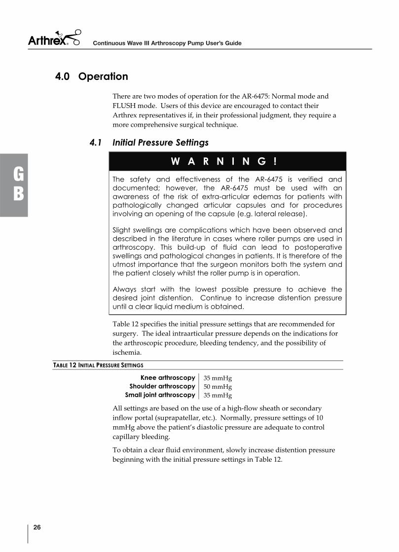
Table 12 specifies the initial pressure settings that are recommended for surgery. The ideal intraarticular pressure depends on the indications for the arthroscopic procedure, bleeding tendency, and the possibility of ischemia.
TABLE 12 INITIAL PRESSURE SETTINGS
Knee arthroscopy 35 mmHg Shoulder arthroscopy 50 mmHg
Small joint arthroscopy 35 mmHg
All settings are based on the use of a high-flow sheath or secondary inflow portal (suprapatellar, etc.). Normally, pressure settings of 10 mmHg above the patient’s diastolic pressure are adequate to control capillary bleeding.
To obtain a clear fluid environment, slowly increase distention pressure beginning with the initial pressure settings in Table 12.
Continuous Wave III Arthroscopy Pump User’s Guide
26
GB
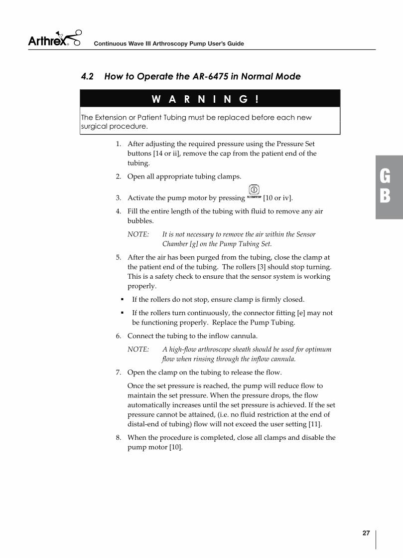
4.2 How to Operate the AR-6475 in Normal Mode
W A R N I N G !
The Extension or Patient Tubing must be replaced before each new surgical procedure.
1. After adjusting the required pressure using the Pressure Set buttons [14 or ii], remove the cap from the patient end of the tubing.
2. Open all appropriate tubing clamps.
3. Activate the pump motor by pressing [10 or iv].
4. Fill the entire length of the tubing with fluid to remove any air bubbles.
NOTE: It is not necessary to remove the air within the Sensor
Chamber [g] on the Pump Tubing Set.
5. After the air has been purged from the tubing, close the clamp at the patient end of the tubing. The rollers [3] should stop turning. This is a safety check to ensure that the sensor system is working properly.
If the rollers do not stop, ensure clamp is firmly closed.
If the rollers turn continuously, the connector fitting [e] may not be functioning properly. Replace the Pump Tubing.
6. Connect the tubing to the inflow cannula.
NOTE: A high-flow arthroscope sheath should be used for optimum
flow when rinsing through the inflow cannula.
7. Open the clamp on the tubing to release the flow.
Once the set pressure is reached, the pump will reduce flow to maintain the set pressure. When the pressure drops, the flow automatically increases until the set pressure is achieved. If the set pressure cannot be attained, (i.e. no fluid restriction at the end of distal-end of tubing) flow will not exceed the user setting [11].
8. When the procedure is completed, close all clamps and disable the pump motor [10].
27
GB
Continuous Wave III Arthroscopy Pump User’s Guide
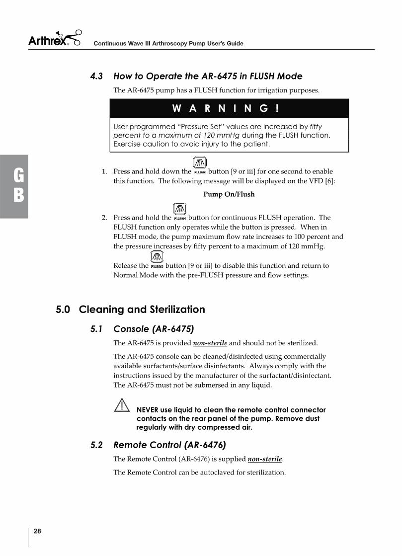
4.3 How to Operate the AR-6475 in FLUSH Mode
The AR-6475 pump has a FLUSH function for irrigation purposes.
W A R N I N G !
User programmed “Pressure Set” values are increased by fifty percent to a maximum of 120 mmHg during the FLUSH function. Exercise caution to avoid injury to the patient.
1. Press and hold down the button [9 or iii] for one second to enable this function. The following message will be displayed on the VFD [6]:
Pump On/Flush
2. Press and hold the button for continuous FLUSH operation. The FLUSH function only operates while the button is pressed. When in FLUSH mode, the pump maximum flow rate increases to 100 percent and the pressure increases by fifty percent to a maximum of 120 mmHg.
Release the button [9 or iii] to disable this function and return to Normal Mode with the pre-FLUSH pressure and flow settings.
5.0 Cleaning and Sterilization
5.1 Console (AR-6475)
The AR-6475 is provided non-sterile and should not be sterilized.
The AR-6475 console can be cleaned/disinfected using commercially available surfactants/surface disinfectants. Always comply with the instructions issued by the manufacturer of the surfactant/disinfectant. The AR-6475 must not be submersed in any liquid.
NEVER use liquid to clean the remote control connector contacts on the rear panel of the pump. Remove dust regularly with dry compressed air.
5.2 Remote Control (AR-6476)
The Remote Control (AR-6476) is supplied non-sterile.
The Remote Control can be autoclaved for sterilization.
Continuous Wave III Arthroscopy Pump User’s Guide
28
GB
Gravity displacement cycles:
270° F to 275° F (132° C – 135° C): exposure time 18 minutes
250° F (121° C): exposure time 60 minutes
Prevacuum cycle:
270° F – 275 °F (132° C – 135° C): 5 Minutes
Sterilizers vary in design and performance characteristics. Cycle parameters and load configuration should always be verified against the sterilizer manufacturer’s instructions.
Cooling – The device must be adequately cooled after being removed from the sterilizer. Do not touch the device during the cooling process. Do not place the device on a cold surface or immerse it in a cold fluid.
The Remote Control can be cleaned/disinfected using commercially available surfactants/surface disinfectants. Always comply with the instructions issued by the manufacturer of the surfactant/disinfectant. It is not designed to be submersed in Gluteraldehyde, Steris®, or Sterrad® disinfectants.
NEVER use liquid to clean the connector contacts of the remote control connector. Remove dust regularly with dry compressed air.
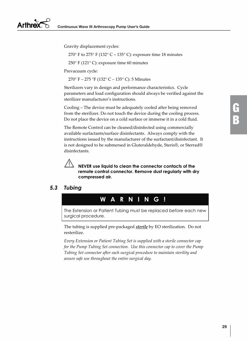
5.3 Tubing
W A R N I N G !
The Extension or Patient Tubing must be replaced before each new surgical procedure.
The tubing is supplied pre-packaged sterile by EO sterilization. Do not resterilize.
Every Extension or Patient Tubing Set is supplied with a sterile connector cap
for the Pump Tubing Set connection. Use this connector cap to cover the Pump
Tubing Set connector after each surgical procedure to maintain sterility and
assure safe use throughout the entire surgical day.
29
GB
Continuous Wave III Arthroscopy Pump User’s Guide
6.0 Maintenance Other than keeping the console and remote control clean (see Section 5.0), there is no recommended maintenance schedule. If the AR-6475 should malfunction, contact an Arthrex representative or Arthrex Technical Support.
7.0 Technical Support For assistance in using the products identified in this User’s Guide, contact an Arthrex representative or call the Arthrex Technical Support Hotlineat 1-888-420-9393, Monday through Friday from 9:00 AM to 5:00 PM EST.
7.1 How to Display the Software Version
Technical Support may request the software version of the pump. These instructions explain how to display the software version.
1. Power OFF the AC mains power switch [8] on the AR-6475.
2. While pressing the FLOW button [12], power ON the AC mains power switch. The software version of the AR-6475 will be displayed on the VFD [6].
Continuous Wave III Arthroscopy Pump User’s Guide
30
GB
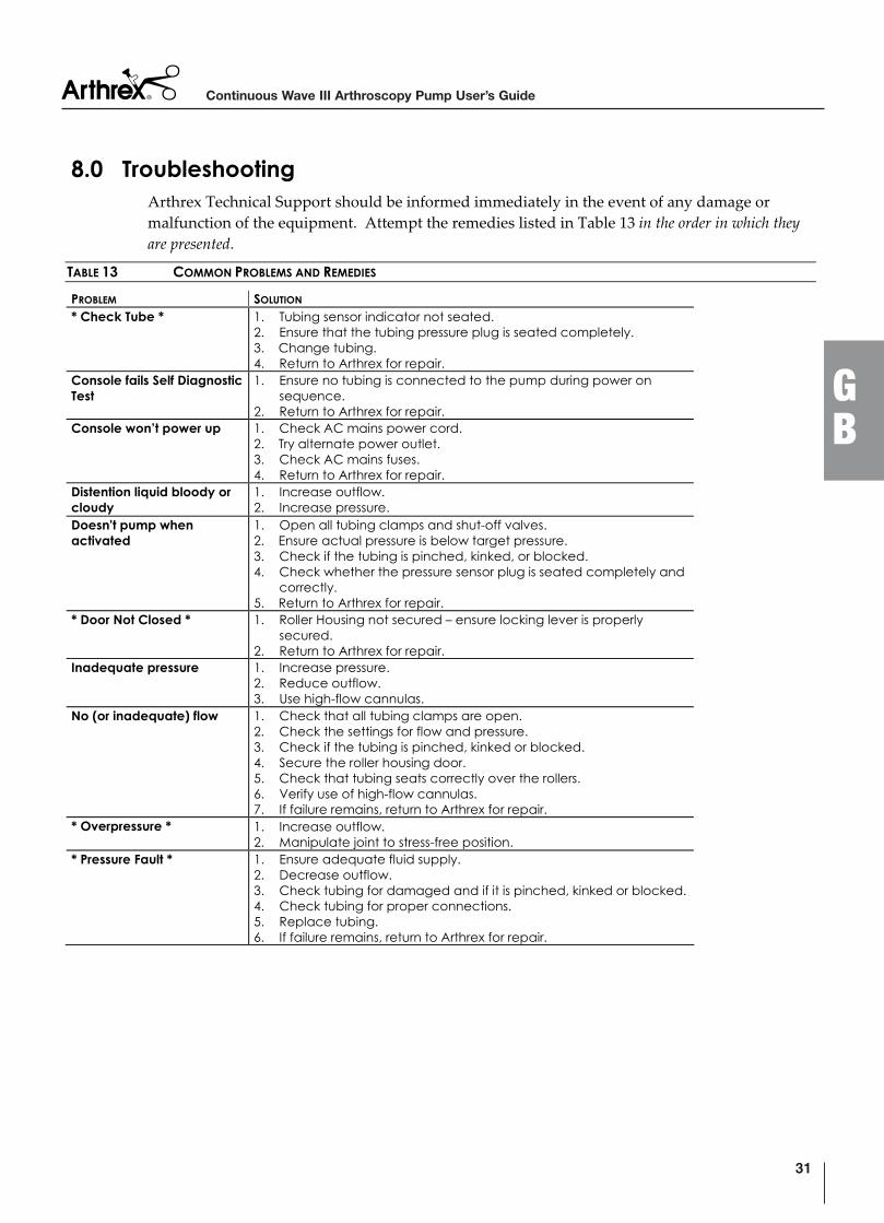
8.0 Troubleshooting Arthrex Technical Support should be informed immediately in the event of any damage or malfunction of the equipment. Attempt the remedies listed in Table 13 in the order in which they
are presented.
TABLE 13 COMMON PROBLEMS AND REMEDIES
PROBLEM SOLUTION
* Check Tube * 1. Tubing sensor indicator not seated. 2. Ensure that the tubing pressure plug is seated completely. 3. Change tubing. 4. Return to Arthrex for repair.
Console fails Self Diagnostic Test
1. Ensure no tubing is connected to the pump during power on sequence.
2. Return to Arthrex for repair. Console won’t power up 1. Check AC mains power cord.
2. Try alternate power outlet. 3. Check AC mains fuses. 4. Return to Arthrex for repair.
Distention liquid bloody or cloudy
1. Increase outflow. 2. Increase pressure.
Doesn't pump when activated
1. Open all tubing clamps and shut-off valves. 2. Ensure actual pressure is below target pressure. 3. Check if the tubing is pinched, kinked, or blocked. 4. Check whether the pressure sensor plug is seated completely and
correctly. 5. Return to Arthrex for repair.
* Door Not Closed * 1. Roller Housing not secured – ensure locking lever is properly secured.
2. Return to Arthrex for repair. Inadequate pressure 1. Increase pressure.
2. Reduce outflow. 3. Use high-flow cannulas.
No (or inadequate) flow 1. Check that all tubing clamps are open. 2. Check the settings for flow and pressure. 3. Check if the tubing is pinched, kinked or blocked. 4. Secure the roller housing door. 5. Check that tubing seats correctly over the rollers. 6. Verify use of high-flow cannulas. 7. If failure remains, return to Arthrex for repair.
* Overpressure * 1. Increase outflow. 2. Manipulate joint to stress-free position.
* Pressure Fault * 1. Ensure adequate fluid supply. 2. Decrease outflow. 3. Check tubing for damaged and if it is pinched, kinked or blocked. 4. Check tubing for proper connections. 5. Replace tubing. 6. If failure remains, return to Arthrex for repair.
31
GB
Continuous Wave III Arthroscopy Pump User’s Guide
9.0 Repair Policy Contact Arthrex for a Return Authorization Number and instructions prior to returning the device.
10.0 Contact Information Arthrex, Inc.
Naples, Florida 34108-1945 USA Tel: +1 239-643-5553 Fax: +1 239-643-6218 Toll-Free Technical Support: +1 888 420-9393, Monday through Friday, 9:00 AM – 5:00 PM ET. Website: www.arthrex.com
Arthrex Med. Inst. GmbH 85757 Karlsfeld, Germany Tel: +1 49 81 31 59 57 29 0 Fax: +1 49 81 31 59 57 63 1 Website: www.arthrex.de
10.1 Compliance Information The Continuous Wave III Arthroscopy Pump (AR-6475) is designed and tested in accordance with 60601-1. According to 60601 this device is Type BF, Class 1, IPX1 rating. According to MDD93/42/EEC, Annex IX, Rule 11, this device is classified as a Class IIa device. EN-55011B (EMC 89/336/CEE): Emission Standards IEC-60601-1 (73/23/CEE): Medical electrical equipment, General Requirements for Safety UL 544: Standard for Safety, Medical and Dental Equipment, being replaced by UL-2601-1 UL 2601-1: Medical Electrical Equipment, General Requirements, US CUL-2601.1: Medical Electrical Equipment, General Requirements, Canada
10.2 Related Documents LAI6302, Pump Stand and Assembly
LM0602, Arthrex Continuous Wave III Arthroscopy Pump – Set Up and Operation and Troubleshooting
AR-6475 Block Diagrams
Continuous Wave III Arthroscopy Pump User’s Guide
32
GB

Appendix A: Block Diagrams for AR-6475 without a Rear Access Panel
33
GB
Continuous Wave III Arthroscopy Pump User’s Guide
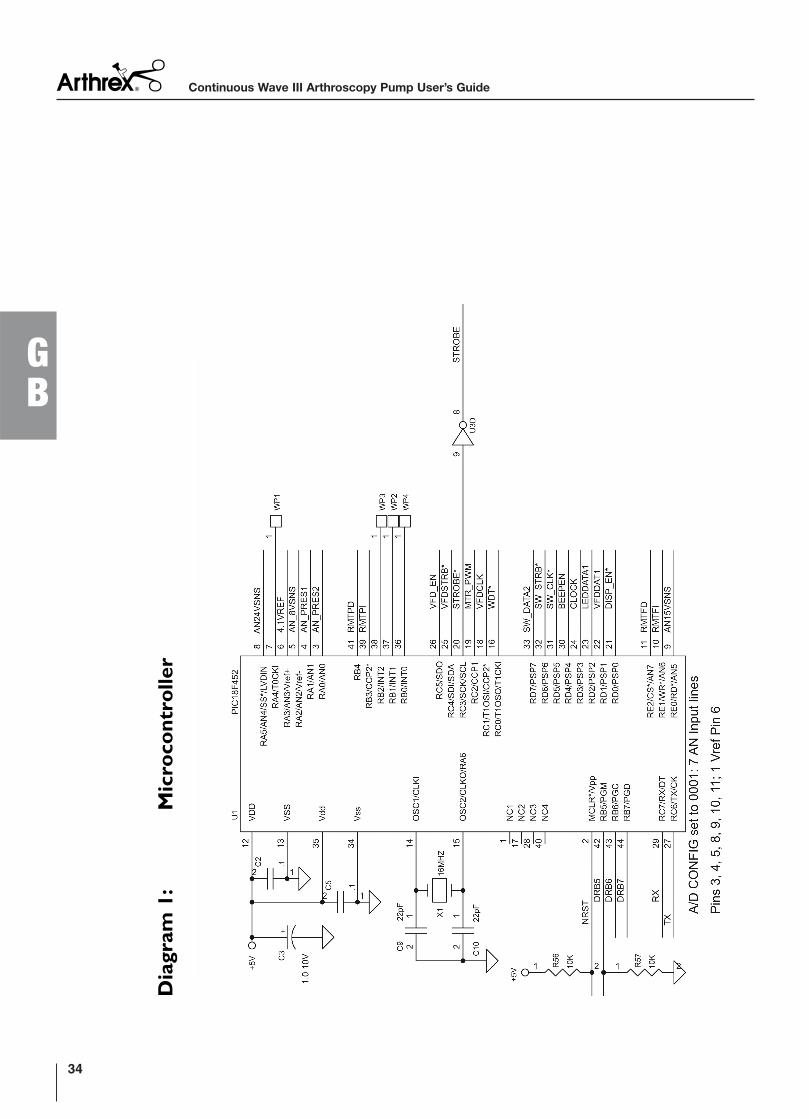
Dia
gram
1:
Mic
ro
co
ntro
ller
Continuous Wave III Arthroscopy Pump User’s Guide
34
GB
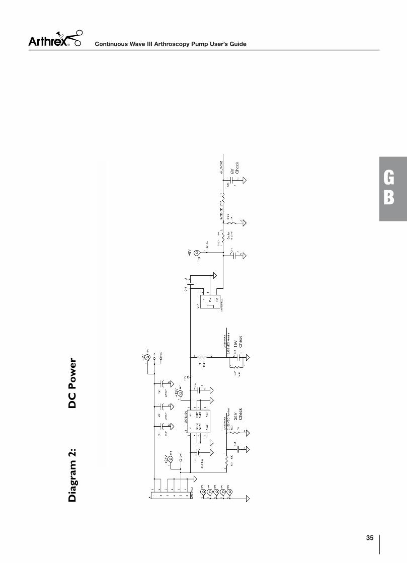
Dia
gram
2:
DC
Po
wer
35
GB
Continuous Wave III Arthroscopy Pump User’s Guide
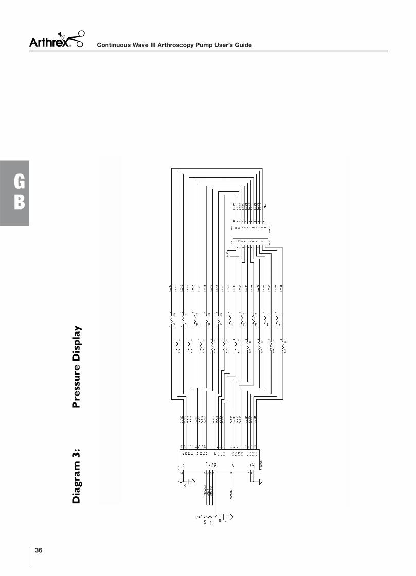
Dia
gram
3:
Pressu
re D
isp
lay
Continuous Wave III Arthroscopy Pump User’s Guide
36
GB
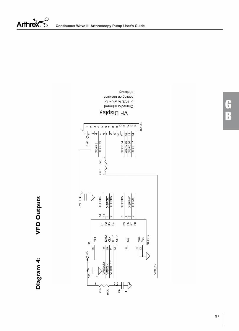
Dia
gram
4:
VF
D O
utp
uts
37
GB
Continuous Wave III Arthroscopy Pump User’s Guide
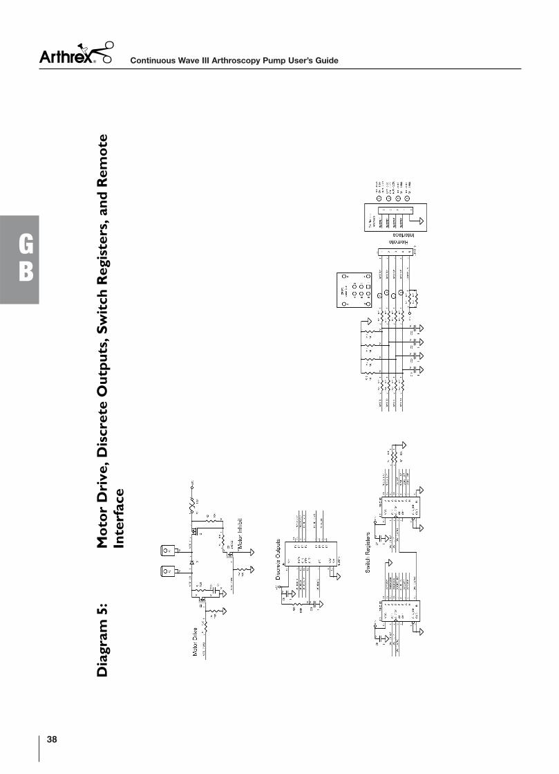
Dia
gram
5:
Mo
to
r D
riv
e, D
iscrete O
utp
uts, S
wit
ch
Regis
ters, an
d R
em
ote
Interfa
ce
Continuous Wave III Arthroscopy Pump User’s Guide
38
GB
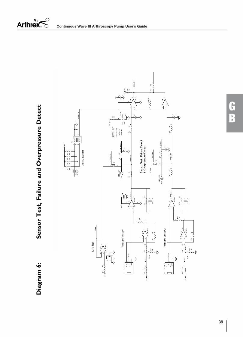
Dia
gram
6:
Sen
so
r T
est, F
ailu
re a
nd
Overp
ressu
re D
etect
39
GB
Continuous Wave III Arthroscopy Pump User’s Guide
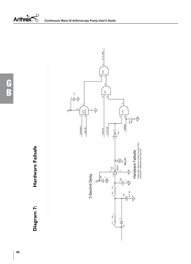
Dia
gram
7:
Hard
ware F
ailsafe
Continuous Wave III Arthroscopy Pump User’s Guide
40
GB
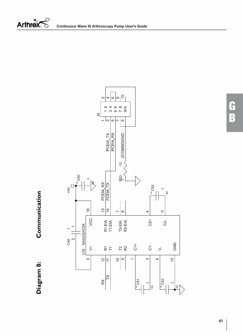
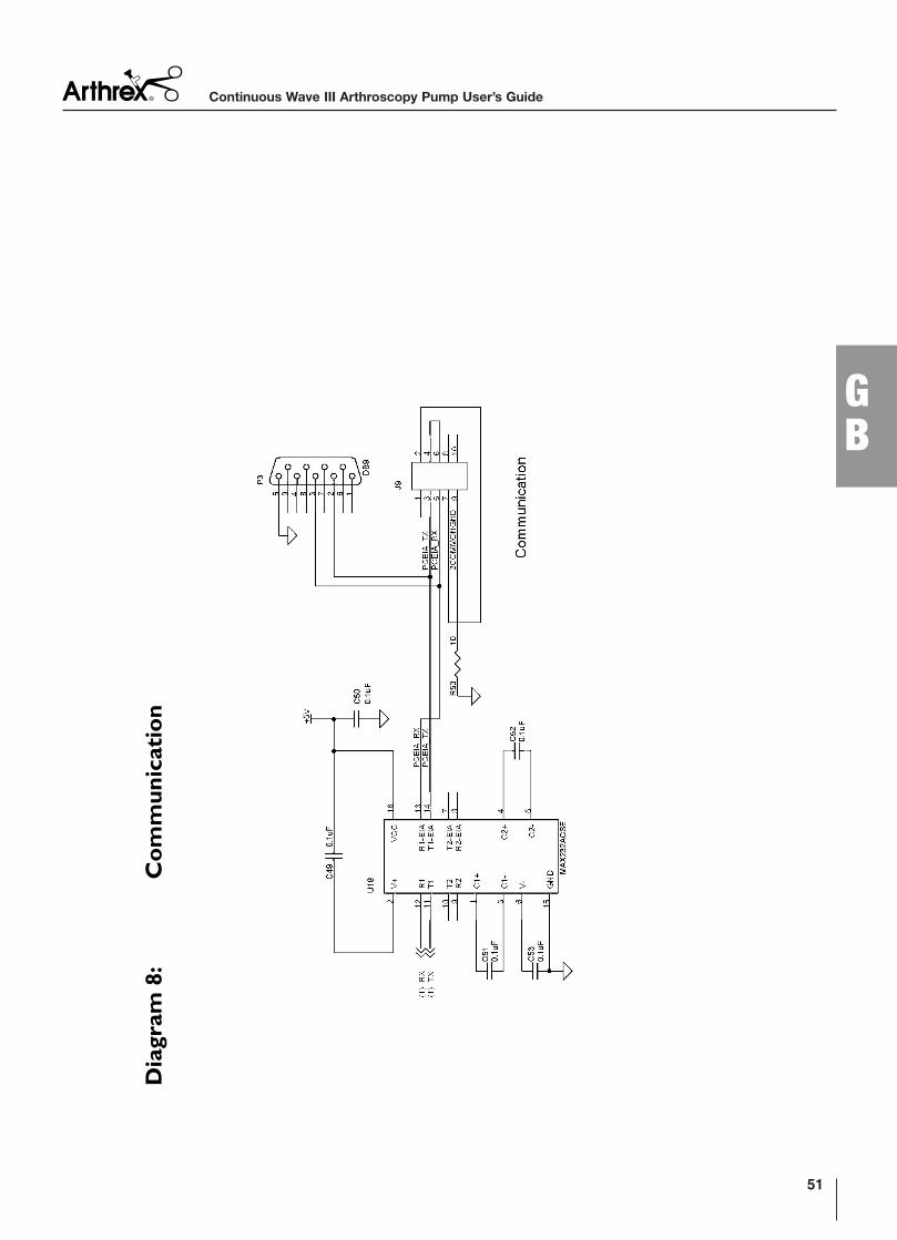
Dia
gram
8:
Co
mm
un
icatio
n
41
GB
Continuous Wave III Arthroscopy Pump User’s Guide
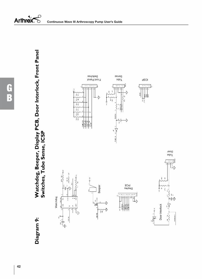
Dia
gram
9:
Watch
do
g, B
eep
er, D
isp
lay P
CB
, D
oo
r I
nterlo
ck, F
ro
nt P
an
el
Sw
itch
es, T
ub
e S
en
se, IC
SP
Continuous Wave III Arthroscopy Pump User’s Guide
42
GB
Appendix B: Block Diagrams for AR-6475 with a Rear Access Panel
43
GB
Continuous Wave III Arthroscopy Pump User’s Guide
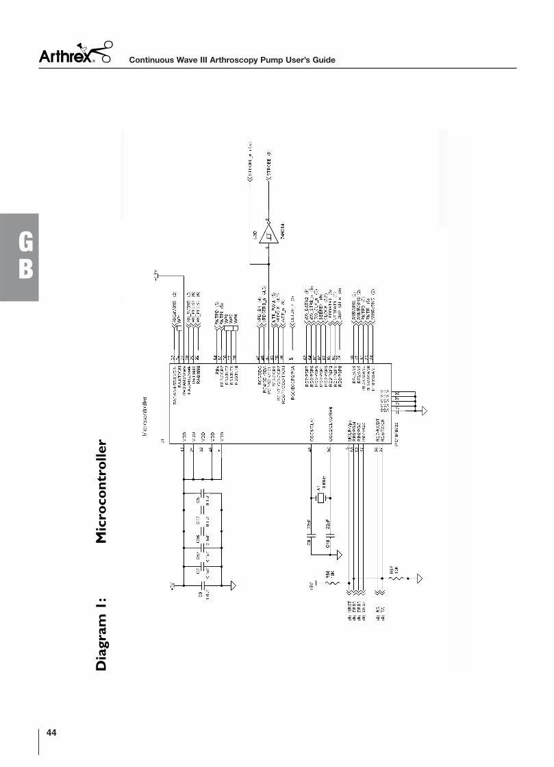
Dia
gram
1:
Mic
ro
co
ntro
ller
Continuous Wave III Arthroscopy Pump User’s Guide
44
GB
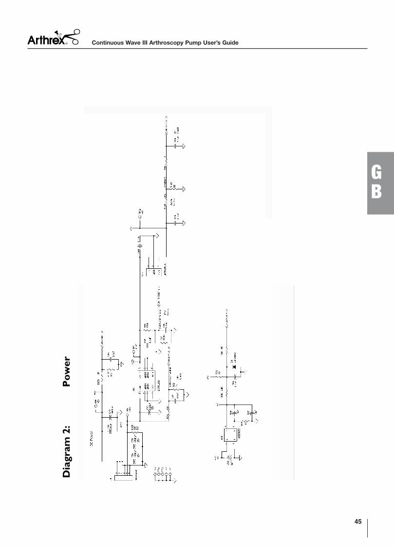
Dia
gram
2:
Po
wer
45
GB
Continuous Wave III Arthroscopy Pump User’s Guide
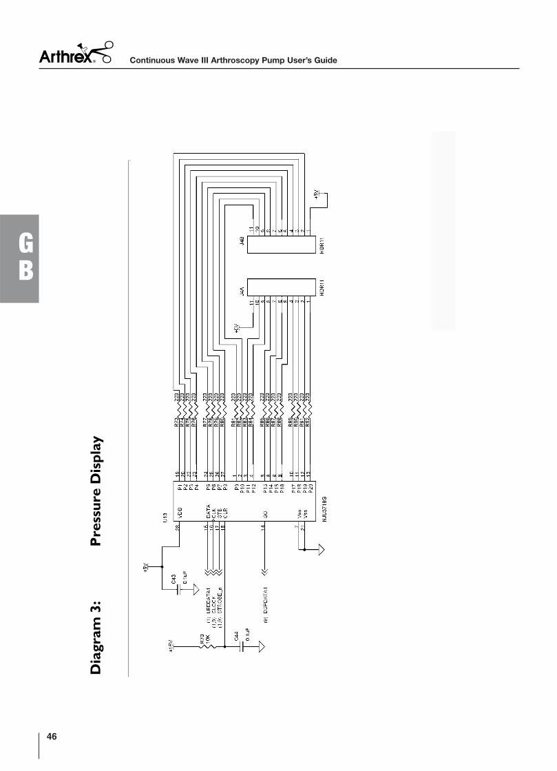
Dia
gram
3:
Pressu
re D
isp
lay
Continuous Wave III Arthroscopy Pump User’s Guide
46
GB
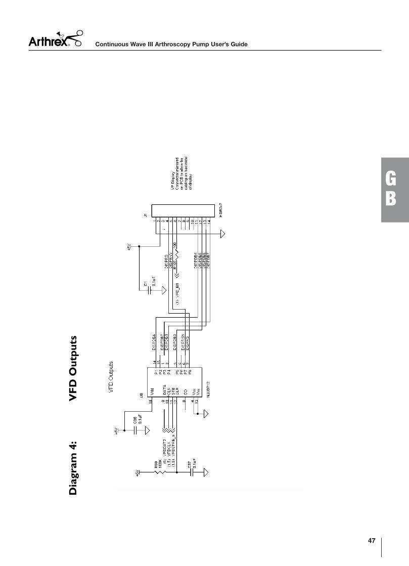
Dia
gram
4:
VF
D O
utp
uts
47
GB
Continuous Wave III Arthroscopy Pump User’s Guide
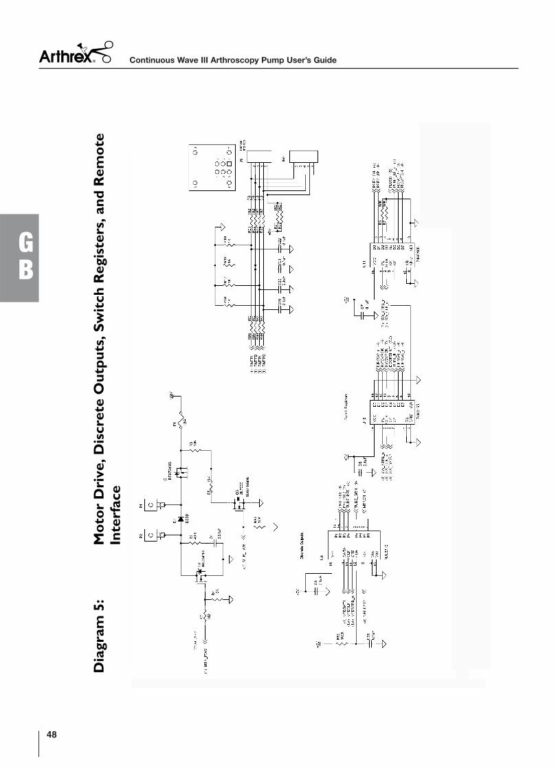
Dia
gram
5:
Mo
to
r D
riv
e, D
iscrete O
utp
uts, S
wit
ch
Regis
ters, an
d R
em
ote
Interfa
ce
Continuous Wave III Arthroscopy Pump User’s Guide
48
GB
Dia
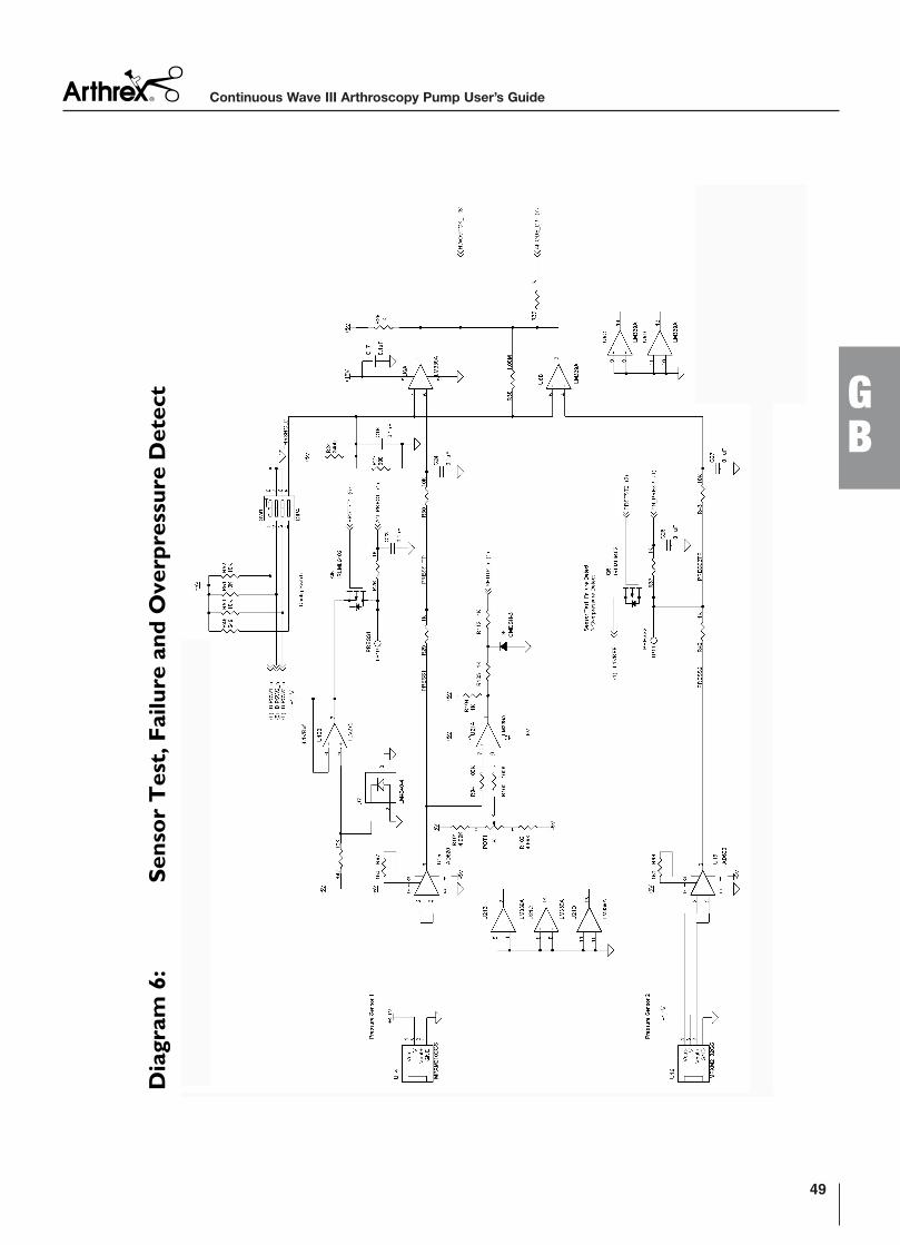
gram
6:
Sen
so
r T
est, F
ailu
re a
nd
Overp
ressu
re D
etect
49
GB
Continuous Wave III Arthroscopy Pump User’s Guide
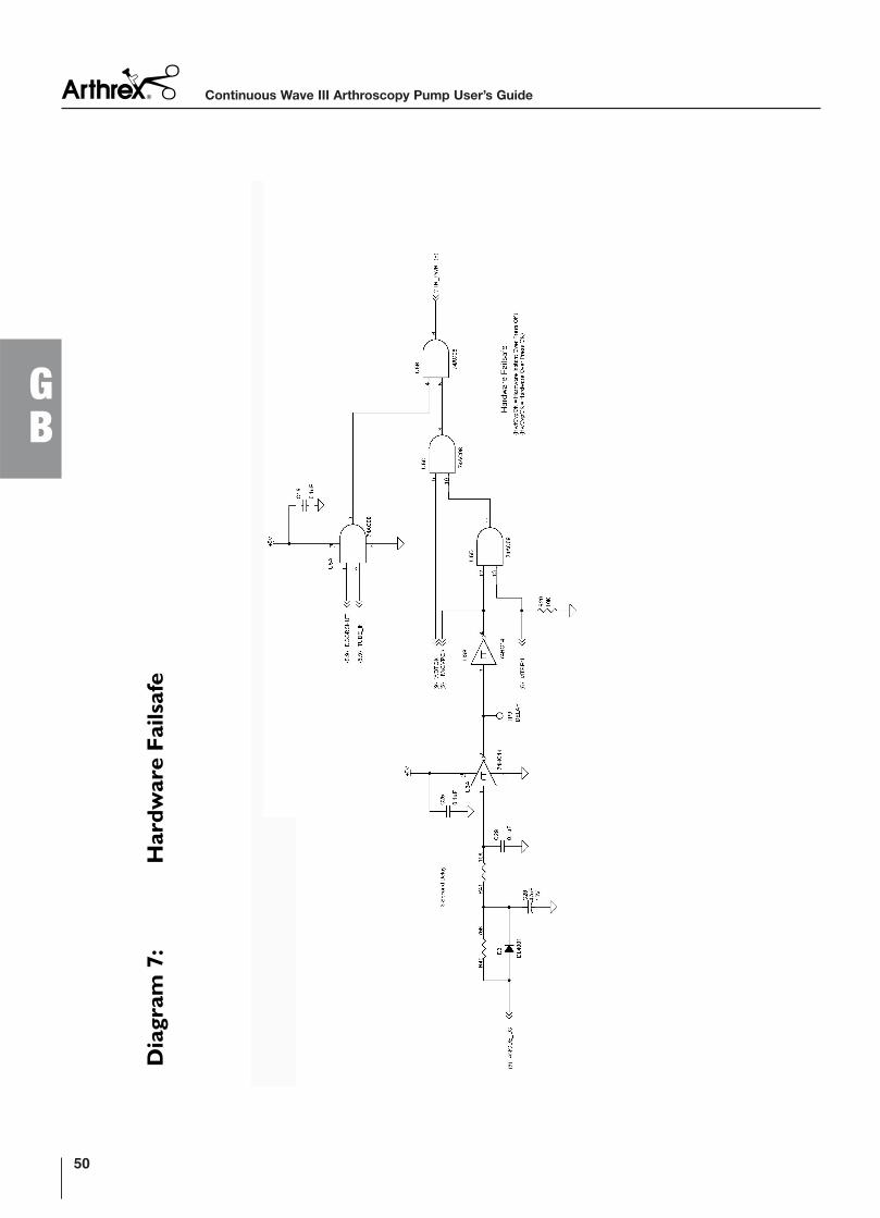
Dia
gram
7:
Hard
ware F
ailsafe
Continuous Wave III Arthroscopy Pump User’s Guide
50
GB
Dia
gram
8:
Co
mm
un
icatio
n
51
GB
Continuous Wave III Arthroscopy Pump User’s Guide
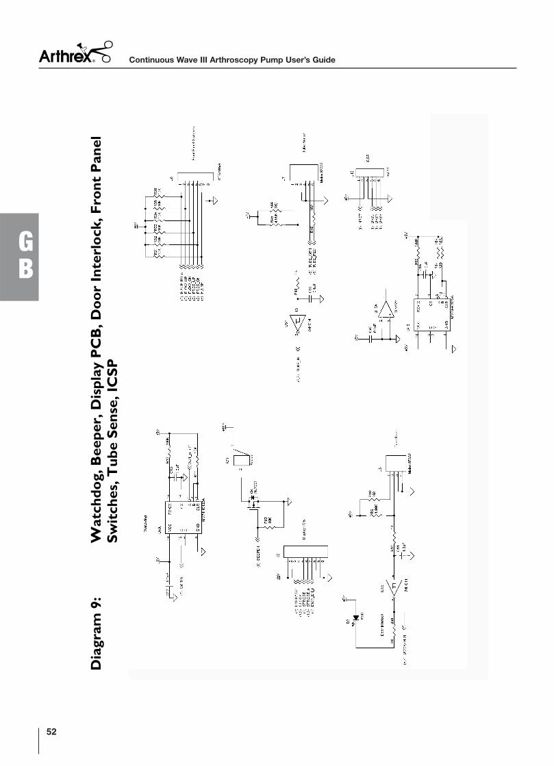
Dia
gram
9:
Watch
do
g, B
eep
er, D
isp
lay P
CB
, D
oo
r I
nterlo
ck, F
ro
nt P
an
el
Sw
itch
es, T
ub
e S
en
se, IC
SP
Continuous Wave III Arthroscopy Pump User’s Guide
52
GB
53
GB
Continuous Wave III Arthroscopy Pump User’s Guide
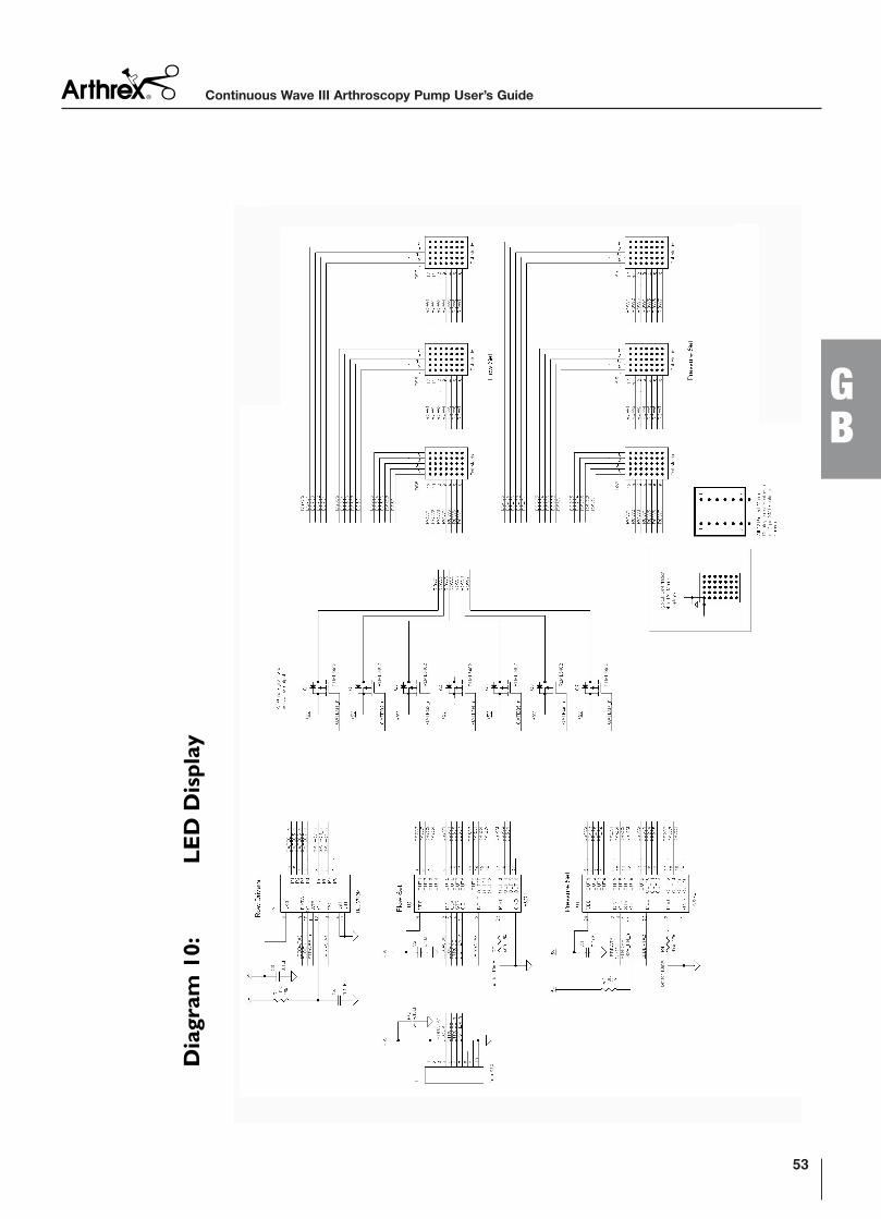
Dia
gram
10:
LE
D D
isp
lay

Continuous Wave III Arthroscopy Pump User’s Guide
54
GB