artigo 3 id pronto - ufsc
TRANSCRIPT

Iberoamerican Journal of Industrial Engineering, Florianópolis, SC, Brasil, V.12, N.24, P. 34-52, 2020.
DESIGN OF AN EMERGENCY CONVEYOR BELT CLAMP FOR HEAVY DUTY DRIFT
BELT INSTALLATION IN UNDERGROUND APPLICATIONS: A CASE STUDY
ABSTRACT: This article provides a summary of the design and operating parameters for an emergency conveyor belt clamp. The static clamp is hydraulically opened and spring control closed to apply a braking force to a belt when there is no hydraulic pressure keeping the clamp faces apart. The braking force is either on or off and not continuously variable during operation. The clamp is designed to be ‘fail safe’ with the clamp closing when hydraulic pressure is lost. Hand calculations were used along with finite element analysis to determine the structural stresses induced by the combined clamping force and belt tension. A twenty Metric Tonne belt capacity (196.1kN lateral load) has been nominated for design purposes. A belt thickness of 50mm has been assumed as a worst case for design purposes. In addition, a dynamic coefficient of friction of 0.2 has been assumed for the contact surfaces between the belt and the clamping beam surfaces. AS1418.1 – Cranes, Hoists and Winches General and AS3990 Mechanical Equipment – Steelwork have been utilized for determining the suitability of the design. The design meets the requirements of the standards for the proposed clamping loads and belt tensions. The combined stresses do not exceed allowable stress or displacement recommendations.
KEYWORDS: Brake. Conveyor belt. Hydraulic Pressure. Installation. Static clamp.
Greg Wheatley ¹Rendage Sachini Sandeepa Chandrasiri 2
¹ College of Science and Engineering, James Cook University, Townsville QLD, Australia - [email protected] Department of Chemistry, University of Colombo, Colombo 07, Sri Lanka
35
Iberoamerican Journal of Industrial Engineering, Florianópolis, SC, Brasil, V.12, N.24, P. 34-52, 2020.
1 INTRODUCTION
Conveyor systems are mechanical devices or assemblies that transport material with minimum effect from one location to another. These are extremely common across many industries especially within the mining industry in Australia (Malek etal, 2015). From different types of conveyers, Belt conveyors are known to be easy and relatively cheap to maintain as they have high loading and unloading capacity, dense material transport is cheap and efficient over long distances and the variability of the bulk material can also be accommodated (Daniyan etal,2014).
The wear and tear of the conveyor belts are affected by many factors including the material, design of the loading bin feeding onto the conveyor belt, belt type, cover rubber, conveyor length, idler spacing, belt speed, scrapers, operational procedures, environmental variations and the quality of the service on the conveyor (Blazej etal, 2017).
Installation of new belt is an expensive process which involves potentially dangerous series of operations that require a wide range of equipment and experienced technicians (Wheatley, 2018). Winders, flake piles and roller stands, turning frames, let off stands etc. are all highly engineered and purpose built pieces of equipment used for this installation process (Wheatley, 2018).
The belt replacement process includes the following general stages. Firstly, a detailed and approved plan for belt replacement must be produced which includes a full hazard and risk reduction plan (Vanamane, 2011). It must also include a review process to minimize the downtime and quality standards which needs to be adhered to. The work permits are issued only if the given plans are approved. The necessary equipment, tools and materials are usually arranged by both the mine and the contracting company as often the larger equipment or splice kits are not owned by the mine (Richard, 2000). The conveyer system is then thoroughly examined to ensure that the new belt will not be damaged. Needless to say, the bulk material must be removed from the conveyor system. The conveyor is locked out as any movement is not permitted. The belt is then de-tensioned and all the required equipment are kept in place. It is very important to place the equipment in such a fashion that the belt is not unnecessarily bent or twisted (Tewari etal, 1991). Any structure or idlers that need to be removed to facilitate belt replacement is then removed. The new belt is temporarily spliced to the old belt which can be removed and wound up on reels while the new belt is drawn onto the system (Richard, 2000). After the old belt is removed, the new belt can have the final splice completed and commissioning can take place which includes ensuring that the belt tracks properly empty and when full of bulk material (Wheatley, 2018). Finally, the area can be fully cleaned and removed of equipment such that normal operations can be reinstated (Anath, 2013).
If there is any substantial change in the elevation of the conveyor system, belt clamps must be used to lock the conveyer belt into one position and prevent runaway (Yusong, 2005). It is at this time the belt clamp on which this paper is concerned comes to place. There are two main types of clamps as braking clamps and emergency (Richard, 2000). The brake clamp uses hydraulic pressure to clamp on the belt to provide adjustable braking while the belt travels down any slope. The emergency clamp uses springs to clamp down and hydraulic pressure to open. As such, if there is a loss of power, the emergency clamps automatically operate and stop the belt from a runaway situation clamps (Selver etal, 2011).
For small conveyors, hand operated tirfors or pull-lifts with properly rated chains and belt clamps are usually used. With larger conveyors this method is not adequate and drives have often been misused to throw slack belt. This is fraught with danger since the forces developed by the drive cannot be properly controlled and may exceed the safe working loads of the clamps, chains etc (Suweken, 2003).
Taking all the above facts into account an emergency static clamping system is designed specifically to assist in installation of heavy-weight conveyor belt onto incline or decline conveyor systems, where hand operated equipment is not sufficient.

36
Iberoamerican Journal of Industrial Engineering, Florianópolis, SC, Brasil, V.12, N.24, P. 34-52, 2020.
2 METHODOLOGY
2.1 DESIGNING OF A STATIC CLAMP SYSTEM
The initial step is to design a static clamp system which incorporates two heavy clamp beams along with associated hardware and a hydraulic control system. The two clamp beams are forced together by eight large springs to apply a clamping force on the belt which in turn creates a controllable braking force to the belt. The amount of braking force available is proportional to the friction coefficient between the steel clamp faces and the rubber belt. Considerations have been made and checks applied respectively to avoid the potential damage to the belt from excessive clamping forces and friction generated heat build-up.
The static belt clamp was used for a belt with a thickness equal to 50 mm and two widths of 1000 and 2000 mm separately. It was assumed that the maximum clamping pressure on the belt does not exceed 2.8 MPa and have a lateral load of 20 Metric Tonnes with a safety factor of two. Therefore the used lateral load for the design is 40 Metric Tonnes (392.3kN).
A dynamic coefficient of friction of 0.2 has been assumed for the contact surfaces between the belt and the clamping beam. Maximum clamping force of 90 Tonnes (882.6kN) with a safety factor of 1.5 has been assumed, where the design load is 135 Tonnes (1323.9kN). The clamp is assumed to be abutted against vertical supports, as a result no lateral loading is assumed on the threaded bars. The clamp is assumed to be mounted with the hydraulic cylinders positioned in the bottom beam where the hydraulic pistons used are unidirectional operating to open the clamp only. It is assumed that the belt has been oriented such that the centerline of the belt is collinear with the centerline of the clamp which results no lateral loading along the length of the clamp.
2.2 HAND CALCULATIONS
2.2.1 DESIGN ACCORDING TO AS1418.1 – CRANES, HOISTS AND WINCHES GENERAL
Australian Standard AS1418.1 – Cranes, Hoists and Winches General specifies that the vertical deflection of the span ((i.e. parallel to the load direction) must be less than 1/500 of the span (<0.2 %) or 60 mm, when no dynamic factor is taken into account in the calculation. The standard also stipulates that the dynamic factor shall be between1.5-2. According to the standard the dead and live load lateral deflection (i.e. at right angles to the load direction) must be less than 1/600 of the span (<0.17 %).
2.2.2 DESIGN ACCORDING TO AS3990 – MECHANICAL EQUIPMENT – STEELWORK
This standard is applicable in the design, fabrication, erection, repair and alteration of steelwork concerning boilers, pressure vessels, lifts, cranes, mining equipment, gas and liquid petroleum piping systems, bulk handling equipment, etc. and uses the working stress design method. Australian Standard 4100 is another commonly used standard for the same purpose. Both standards essentially compare the limit state design method and the permissible stress design method. A comparison of case studies of mining equipment concluded that although the theoretical comparisons showed potentially large differences in individual members, there was little practical difference in the overall machine designs (MARX, 2004).

37
Iberoamerican Journal of Industrial Engineering, Florianópolis, SC, Brasil, V.12, N.24, P. 34-52, 2020.
2.3 ANALYSIS OF TEMPERATURE RISE
The temperature rise of the clamps during an emergency braking scenario was estimated using a worst-case application on a large slope conveyor system. For the conveyor system which the clamps are being designed, the carry side belt length is 3370 m. The belt weight is 165 kg/m. The belt speed during operation will be 5 m/s. The slope of the conveyor incline is 15 degrees and the system is deemed to require four clamping stations. The belt width is 1.8 m and the clamp length is 0.4 m with a dynamic factor set at 1.5. The distance of the clamp on either side of the belt which is not in contact is therefore 0.3865 m. The temperature rise during an emergency braking situation was estimated.
2.4 FINITE ELEMENT ANALYSIS (FEA)
Autodesk Inventor Professional 2014 was used to analyze the Static Belt Clamp. The Static Belt Clamp model was constructed and used to produce the construction drawings.
3 RESULTS AND DISCUSSION
3.1 RESULTS OF THE DESIGN ACCORDING TO AS1418.1 – CRANES, HOISTS AND WINCHES GENERAL
For the final design as per the results of the finite elements analysis, it was found that the result of vertical deflection of the span is 2.62 mm which is below the required standard deflection of 4.4 mm. For the lateral deflection of the final design, the resulted value was 2.62 mm which is lower than the required standard value of 3.7 mm. Hence the design satisfies the requirements of the AS 1418.1 standard.
3.2 RESULTS FOR THE DESIGN ACCORDING TO AS3990 – MECHANICAL EQUIPMENT – STEELWORK
In order to comply with Australian Standard AS3990 – Mechanical Equipment – Steelwork a number of parameters need to be known to make all the necessary computations. The Standard should be referenced for most of the relevant equations as only the results of the calculations are reported here. The standard is quite broad so different design applications will activate different relevant sections of the standard.
The ultimate tensile strength of the material used in the construction of the clamp is 480 MPa. The yield strength is 360 MPa with a Young’s modulus of 200 GPa. A standard 400WC328 cross section was used for the construction. The width of the section is 400 mm and the depth is 400 mm. The flange thickness and web thickness are 25 and 20 mm respectively. The gross cross section is 27,000 mm2. The cross section of the web is 8,000 mm2 while the flange cross section is 10,000 mm2. The clear distance between the flanges is 350 mm and the greater distance from the section neutral axis is 200 mm. The distance from outstand of the flange beyond the line of connection to a web is 190 mm. The second moment of inertia about the x axis is 776x106 mm4 and about the y axis is 267x106 mm4. The length of the beam is 2200 mm.
38
Iberoamerican Journal of Industrial Engineering, Florianópolis, SC, Brasil, V.12, N.24, P. 34-52, 2020.
3.2.1 MAXIMUM PERMISSIBLE STRESS
The maximum permissible stress as per the standard clause 5.2 is calculated by equation 1below,
Fb = 0.66 Fy (1)
Where Fb = Maximum permissible stressFy = The yield stress pertaining to the steel used
The yield stress of the material as an ‘I’ type beam is to be used which equates to 238 MPa. The maximum permissible compressive stress must be greater than the general amount of 216 MPa, the amount for all beams is 244 MPa, for other flanges or plates the value is 254 MPa and the permissible compressive stress for bending is 238 MPa.
3.2.2 MAXIMUM PERMISSIBLE STRESS IN A BEAM BENT
The maximum permissible stress in the beam is estimated using a maximum permissible bending stresses table. When bent about the axis of maximum strength is thusly calculated as 162 MPa, noticing that the elastic buckling stress of the beam is 8924 MPa.
3.2.3 ELASTIC BUCKLING STRESS (FOB)
The elastic buckling stress of the beam is calculated using the below equation 2 below.
FOB= K1 (A+ K2B) C2/C1 (2)
Where, K1 = a coefficient to allow for the reduction in thickness or breadth of the flanges between the points of effective lateral restraint, in this case which equals to 1
K2 = a coefficient to allow for the inequality of the flanges, in this case which equals to 0.5 A = Variable 1 where the value in this case is 6231.8B = Variable 2 where the value in this case is 5585.3C1= lesser distance from the section neutral axis to the extreme fibersC2= longest distance from the section neutral axis to the extreme fibersThe resulted elastic buckling stress of the beam is 8924 MPa.
3.2.4 MAXIMUM SHEAR STRESS
The maximum shear stress is calculated using the below equation 3,
Fvm = 0.45 Fy (3)
Where, Fvm = maximum shear stressFy = The yield stress pertaining to the steel usedThe maximum permissible shear stress equals to 162 MPa in this case.
39
Iberoamerican Journal of Industrial Engineering, Florianópolis, SC, Brasil, V.12, N.24, P. 34-52, 2020.
3.2.5 AVERAGE SHEAR STRESS
The average shear stress is calculated using the below equation 4,
Fv = 0.37 Fy (4)Where, Fv = average shear stressFy = The yield stress pertaining to the steel usedThe average shear stress for an unstiffened web must the less of 133 MPa and thus the
permissible average shear stress must not exceed 133 MPa.
3.2.6 AXIAL STRESSES IN UNCASED STRUTS
The axial stress in uncased struts is calculated using below equation 5,
Fac = 1/Ω [(Fy+ (η +1)Foc )/2] - √ [(Fy+ (η +1)Foc )/2)2 - FyFoc] (5)
Where, Fac = Axial StressΩ = Load factor taken as 1/0.60η = 0.015Foc = Eular critical stress = 4030 MpaFy = The yield stress pertaining to the steel usedFor this case the axial stresses in uncased struts are calculated and the struts are deemed to be
loaded concentrically. The variable η is therefore equal to 0.015. As such the elastic buckling strength of the strut in the x axis is equal to 11,648 MPa while in the y axis it is equal to 4,030 MPa. The Euler critical stress is calculated to be 4030 MPa. Therefore, the permissible average compressive strength is 212.6 MPa. The average compressive strength for slender leg struts is 180 MPa.
3.2.6 AXIAL TENSILE STRENGTH
The maximum shear stress is calculated using the below equation 6,
Fat = 0.60 Fy (6)Where, Fat = Axial tensile strength Fy = The yield stress pertaining to the steel usedFor tension members, the axial tensile stress is set as a maximum to be 0.60 times the yield
strength. As such, the permissible maximum axial tensile strength is 216 MPa. A summary of permissible stresses are tabulated in below Table 1.
Table 1 - Summary of permissible stresses
Value (MPa)216 238 238238 180162
133.2
Permissible stressAxial tensile stress
Permissible stress due to bending Permissible compressive stress, bending about x-axis Permissible compressive stress, bending about y-axis
Permissible average compressive stress Permissible maximum shear stress Permissible average shear stress

40
Iberoamerican Journal of Industrial Engineering, Florianópolis, SC, Brasil, V.12, N.24, P. 34-52, 2020.
The total clamping force is calculated to be 900 kN. The friction coefficient between steel and rubber is set at 0.109. The number of friction surfaces is two as the clamp operates on both sides of the belt. The braking force is therefore 196 kN. The length of the beam is 2200 mm. As such, the bending moment in the x axis is 4.95E08 Nmm and in the y axis is 1.08E8 Nmm.
The calculated compressive bending stress in the x axis is therefore 127.6 MPa while in the y axis is 80.8 MPa. The percentage of the maximum allowable is therefore 53.7% in the x axis and 34.0% in the y axis. The sum is therefore 87.7% and hence the design complies with AS3990.
3.3 ANALYSIS OF THE TEMPERATURE RISE
Based on the data given in the methodology section, the kinetic energy of the belt while operating is 6,950,625 J and the potential energy is 5,442,769 J. The sum of kinetic and potential energy 12,393,394 J is required for the braking system to stop the belt. The time required to stop the belt is deemed to be 10 s. The required power is therefore 1,239,339 W. The heat flux is therefore 430,326 W/m2. As such the single stop temperature rise at each clamp is therefore 56 ºC plus ambient temperature for each clamp.
The clamps are seen to rise by 56 ºC which will not harm the belt. The conveyor belt is designed to handle a temperature of 56 ºC as it is designed for use in remote Australian mines where surface temperature of the belt can easily exceed this level. A worst-case application on a large slope conveyor system is used for the calculation. The clamps are seen to rise by 56 ºC which will not harm the belt.
3.4 FINITE ELEMENT ANALYSIS
The meshing used in the analysis was the default mesh specified by Inventor which was used mainly to reduce computational time in the analysis. In addition to the default mesh, face sizings were included to increase the accuracy of the results. A face sizing of 1 mm was included at the surfaces of the axis of rotation. By introducing this mesh refinement, a structural error in the analysis of 0.64 mJ was found. This is relatively small and not near the areas of maximum stress, at which, error of approximately zero is observed. This negligible error verifies the mesh as accurate giving confidence in the results.
The static belt clamp was designed to be constructed from AS3679.2-400 grade material which has a yield stress of 360 MPa and a tensile strength of 480 MPa. The steel cord conveyor belt has a Young’s modulus of 190 GPa. The static belt clamp was fixed on the bottom beam as per Figure 1 below. The top and bottom beams were also supported by a sliding surface as per the Figure 2 below.
Figure 1 - Fixture area on the bottom beam.

41
Iberoamerican Journal of Industrial Engineering, Florianópolis, SC, Brasil, V.12, N.24, P. 34-52, 2020.
The applied load on the belt and clamp are illustrated in below Figure 3 and 4 respectively.
Figure 2 - Vertical mounting areas that offer a surface for the top and bottom beams to move against.
Figure 3 - Load applied to belt.
Figure 4 - Load applied to clamp.

42
Iberoamerican Journal of Industrial Engineering, Florianópolis, SC, Brasil, V.12, N.24, P. 34-52, 2020.
A safety factor of 1.5 was used on the compressive load for a total of 135 Tonnes force (1325.7kN). A safety factor of 2 was used for the lateral pull of the belt for a total of 40 Tonnes force (392.3kN) whereas the static belt clamp will only be rated for a braking force of 20 Tonnes (196kN).
3.4.1 USE OF A 2000MM WIDE BELT
Finite elements analysis was performed to evaluate the performance of a 2000mm wide belt under emergency braked conditions. Figure 5 illustrates the maximum stress on the overall clamp while Figure 6 depicts the stress generated on the belt.
Figure 5 - Overall clamp maximum stress for 2000mm wide belt
The maximum stress generated on the clamp is 213.8MPa while a maximum stress of 0.859 MPa stress is created at the edges of the belt where the clamp is attached to. According to the Australian standard 3990, the maximum allowable stress for clamp and belt is respectively 360 MPa and 2.8 MPa. In the novel design with a 2000m wide belt the maximum allowable stress for clamp and belt is respectively 213.8 MPa and 0.86 MPa, which is well below the requires values.
Below Figure 7 and 8 depicts the maximum stress of the overall clamp for XX and YY respectively,
Figure 6 - Stress on 2000mm wide belt.

43
Iberoamerican Journal of Industrial Engineering, Florianópolis, SC, Brasil, V.12, N.24, P. 34-52, 2020.
According to the Australian standard AS 3990 the maximum overall clamp stress for XX and YY are 238 MPa. In the new design the maximum overall clamp stress for XX and YY are 108.7 and 50.82 MPa respectively which are lower than the required level.
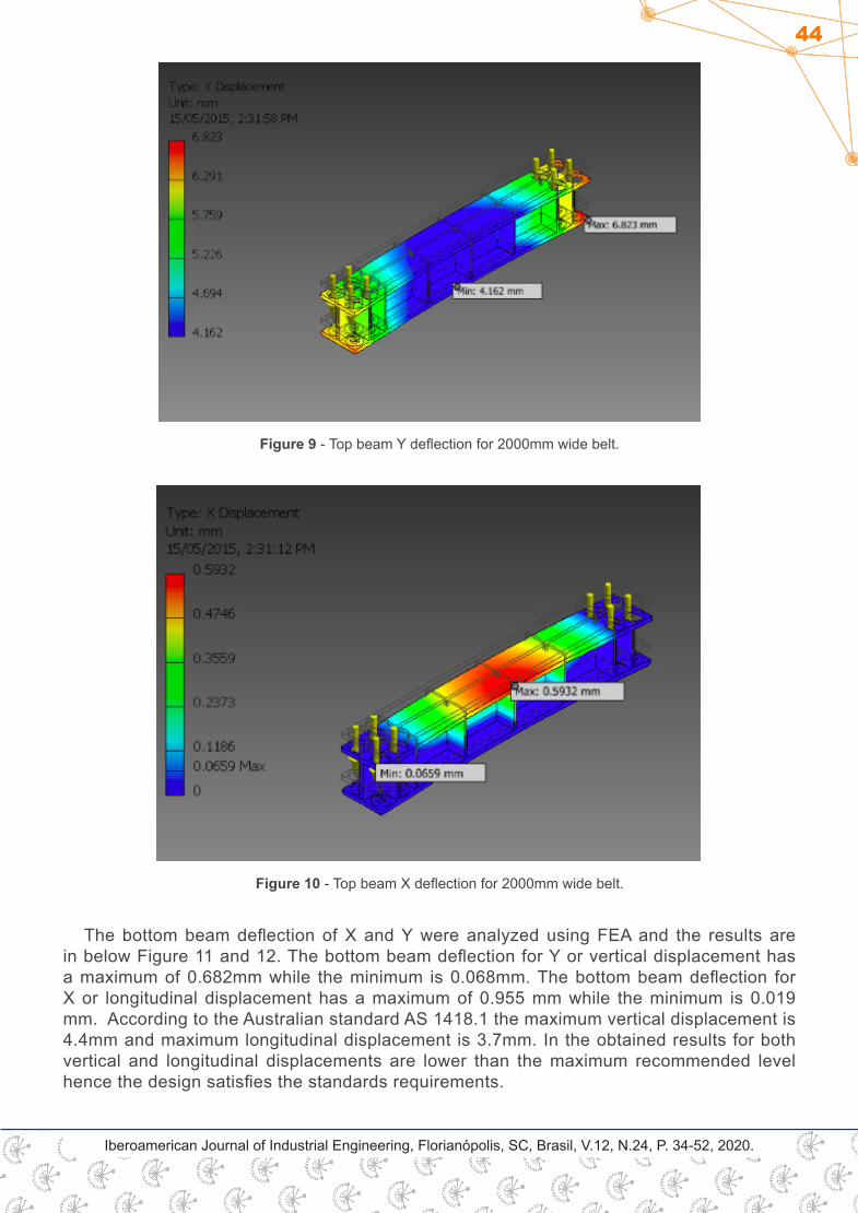
The top beam deflection of X and Y were analyzed using FEA and the results are in below Figure 9 and 10. The top beam deflection for Y or vertical displacement has a maximum of 6.823mm while the minimum is 4.162 mm. The top beam deflection for X or longitudinal displacement has a maximum of 0.5932mm while the minimum is 0.0659 mm. According to the Australian standard AS 1418.1 the maximum vertical displacement is 4.4mm and maximum longitudinal displacement is 3.7mm. In the obtained results vertical displacement is higher than the maximum recommended level while the longitudinal displacement satisfies the requirement.
Figure 7 - Overall clamp maximum XX stress for 2000mm wide belt.
Figure 8 - Overall clamp maximum YY stress for 2000mm wide belt
44
Iberoamerican Journal of Industrial Engineering, Florianópolis, SC, Brasil, V.12, N.24, P. 34-52, 2020.
Figure 9 - Top beam Y deflection for 2000mm wide belt.
Figure 10 - Top beam X deflection for 2000mm wide belt.
The bottom beam deflection of X and Y were analyzed using FEA and the results are in below Figure 11 and 12. The bottom beam deflection for Y or vertical displacement has a maximum of 0.682mm while the minimum is 0.068mm. The bottom beam deflection for X or longitudinal displacement has a maximum of 0.955 mm while the minimum is 0.019 mm. According to the Australian standard AS 1418.1 the maximum vertical displacement is 4.4mm and maximum longitudinal displacement is 3.7mm. In the obtained results for both vertical and longitudinal displacements are lower than the maximum recommended level hence the design satisfies the standards requirements.

45
Iberoamerican Journal of Industrial Engineering, Florianópolis, SC, Brasil, V.12, N.24, P. 34-52, 2020.
Figure 11 - Bottom beam Y deflection for 2000mm wide belt
Figure 12 - Bottom beam X deflection for 2000mm wide belt
3.4.2 USE OF A 1000MM WIDE BELT
Finite elements analysis was performed to evaluate the performance of a 1000mm wide belt under braked conditions. Figure 13 illustrates an overall clamp maximum stress while Figure 14 depicts the stress generated on the belt.

46
Iberoamerican Journal of Industrial Engineering, Florianópolis, SC, Brasil, V.12, N.24, P. 34-52, 2020.
Figure 13 - Overall clamp maximum stress for 1000mm wide belt
Figure 14 - Stress on 1000mm wide belt
The maximum stress generated on the clamp is 256.7MPa while a maximum stress of 1.467 MPa stress is created at the edges of the belt where the clamp is attached to. According to the Australian standard 3990, the maximum allowable stress for clamp and belt is respectively 360 MPa and 2.8 MPa. In the novel design with a 1000m width belt the maximum allowable stress for clamp and belt is respectively 256.7 MPa and 1.467 MPa, which is well below the requires values.
Below Figure 15 and 16 depicts the maximum stress of the overall clamp for XX and YY respectively,

47
Iberoamerican Journal of Industrial Engineering, Florianópolis, SC, Brasil, V.12, N.24, P. 34-52, 2020.
Figure 15 - Overall clamp maximum XX stress for 1000mm wide belt
Figure 16 - Overall clamp maximum YY stress for 1000mm wide belt
According to the Australian standard AS 3990 the maximum overall clamp stress for XX and YY are 238 MPa. In the new design the maximum overall clamp stress for XX and YY are 74.03 and 107.3 MPa respectively which are lower than the required level and satisfies the standard conditions.
The top beam deflection of X and Y were analyzed using FEA and the results are in below Figure 17 and 18. The top beam deflection for Y or vertical displacement has a maximum of 2.62mm while the minimum is 0.118 mm. The top beam deflection for X or longitudinal displacement has a maximum of 0.106 mm while the minimum is 0.088 mm. According to the Australian standard AS 1418.1 the maximum vertical displacement is 4.4mm and maximum longitudinal displacement is 3.7mm. In the obtained results both vertical and longitudinal displacements satisfies the standards requirement.

48
Iberoamerican Journal of Industrial Engineering, Florianópolis, SC, Brasil, V.12, N.24, P. 34-52, 2020.
Figure 17 - Top beam Y deflection for 1000mm wide belt
Figure 18 - Top beam X deflection for 1000mm wide belt
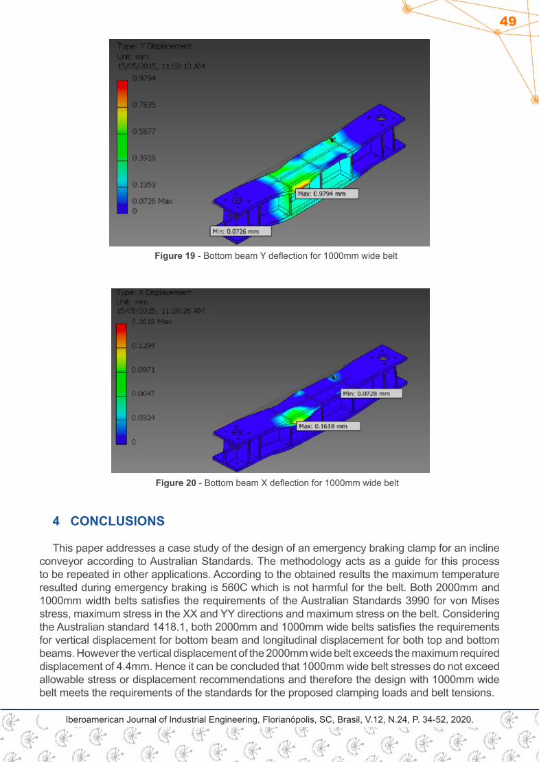
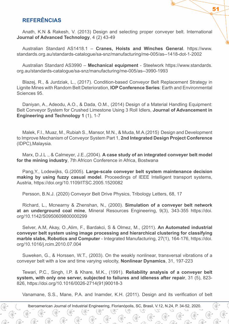
The bottom beam deflection of X and Y were analyzed using FEA and the results are in below Figure 19 and 20. The bottom beam deflection for Y or vertical displacement has a maximum of 0.979 mm while the minimum is 0.0726 mm. The bottom beam deflection for X or longitudinal displacement has a maximum of 0.1618 mm while the minimum is 0.0728 mm. According to the Australian standard AS 1418.1 the maximum vertical displacement is 4.4mm and maximum longitudinal displacement is 3.7mm. In the obtained results for both vertical and longitudinal displacements are lower than the maximum recommended level hence the design satisfies the standards requirement.
49
Iberoamerican Journal of Industrial Engineering, Florianópolis, SC, Brasil, V.12, N.24, P. 34-52, 2020.
4 CONCLUSIONS
This paper addresses a case study of the design of an emergency braking clamp for an incline conveyor according to Australian Standards. The methodology acts as a guide for this process to be repeated in other applications. According to the obtained results the maximum temperature resulted during emergency braking is 560C which is not harmful for the belt. Both 2000mm and 1000mm width belts satisfies the requirements of the Australian Standards 3990 for von Mises stress, maximum stress in the XX and YY directions and maximum stress on the belt. Considering the Australian standard 1418.1, both 2000mm and 1000mm wide belts satisfies the requirements for vertical displacement for bottom beam and longitudinal displacement for both top and bottom beams. However the vertical displacement of the 2000mm wide belt exceeds the maximum required displacement of 4.4mm. Hence it can be concluded that 1000mm wide belt stresses do not exceed allowable stress or displacement recommendations and therefore the design with 1000mm wide belt meets the requirements of the standards for the proposed clamping loads and belt tensions.
Figure 20 - Bottom beam X deflection for 1000mm wide belt
Figure 19 - Bottom beam Y deflection for 1000mm wide belt

50
Iberoamerican Journal of Industrial Engineering, Florianópolis, SC, Brasil, V.12, N.24, P. 34-52, 2020.
RESUMO: Este artigo fornece um resumo do projeto e dos parâmetros operacionais para uma braçadeira de correia transportadora de emergência. A braçadeira estática é aberta hidraulicamente e o controle da mola é fechado para aplicar uma força de frenagem a uma correia quando não há pressão hidráulica mantendo a braçadeira com faces separadas. A força de frenagem é ligada ou desligada e não é continuamente variável durante a operação. A braçadeira é projetada para ser “à prova de falhas”, fechando quando a pressão hidráulica é perdida. Foram utilizados cálculos manuais e análise de elementos finitos para determinar as tensões estruturais induzidas pela força de fixação combinada e tensão da correia. Uma esteira de 20 toneladas métricas (carga lateral de 196,1 kN) foi indicada para fins de projeto. Uma espessura de cinta de 50 mm foi considerada o pior caso para fins de projeto. Além disso, um coeficiente dinâmico de atrito de 0,2 foi assumido para as superfícies de contato entre a correia e as superfícies da viga de fixação. Foram utilizadas as normas AS1418.1 - Guindastes, Talhas e Guinchos Gerais e AS3990 Equipamentos Mecânicos - Estrutura em Aço para determinar a adequação do projeto. O projeto atende aos requisitos das normas para as cargas de fixação e tensões da correia propostas, sendo que as tensões combinadas não excedem as recomendações de tensão ou deslocamento permitidas.
PALAVRAS-CHAVE: Freio. Correia transportadora. Pressão hidráulica. Instalação. Pinça estática.
PROJETO DE UM GRAMPO DE CORREIA TRANSPORTADORA DE EMERGÊNCIA
PARA INSTALAÇÃO DE CORREIA DE TRAÇÃO PESADA EM APLICAÇÕES
SUBTERRÂNEAS: UM ESTUDO DE CASO
Originais recebidos em: 11/08/2020Aceito para publicação em: 10/09/2020
51
Iberoamerican Journal of Industrial Engineering, Florianópolis, SC, Brasil, V.12, N.24, P. 34-52, 2020.
REFERÊNCIAS
Anath, K.N & Rakesh, V. (2013) Design and selecting proper conveyer belt. International Journal of Advanced Technology, 4 (2) 43-49
Australian Standard AS1418.1 – Cranes, Hoists and Winches General. https://www.standards.org.au/standards-catalogue/sa-snz/manufacturing/me-005/as--1418-dot-1-2002
Australian Standard AS3990 – Mechanical equipment - Steelwork https://www.standards.org.au/standards-catalogue/sa-snz/manufacturing/me-005/as--3990-1993
Blazej, R., & Jurdziak, L., (2017). Condition-based Conveyor Belt Replacement Strategy in Lignite Mines with Random Belt Deterioration, IOP Conference Series: Earth and Environmental Sciences 95.
Daniyan, A., Adeodu, A.O., & Dada, O.M., (2014) Design of a Material Handling Equipment: Belt Conveyor System for Crushed Limestone Using 3 Roll Idlers, Journal of Advancement in Engineering and Technology 1 (1), 1-7
Malek, F.I., Muaz, M., Rubiah S., Mansor, M.N., & Muda, M.A.(2015) Design and Development to Improve Mechanism of Conveyor System Part 1, 2nd Integrated Design Project Conference (IDPC),Malaysia.
Marx, D.J.L ., & Calmeyer, J.E.,(2004). A case study of an integrated conveyer belt model for the mining industry, 7th Africon Conference in Africa, Bostwana
Pang,Y., Lodewijks, G.(2005). Large-scale conveyer belt system maintenance decision making by using fuzzy casual model. Proceedings of IEEE Intelligent transport systems, Austria, https://doi.org/10.1109/ITSC.2005.1520082
Persson, B.N.J. (2020) Conveyor Belt Drive Physics, Tribology Letters, 68, 17
Richard, L., Mcnearny & Zhenshan, N., (2000). Simulation of a conveyer belt network at an underground coal mine, Mineral Resources Engineering, 9(3), 343-355 https://doi.org/10.1142/S0950609800000299
Selver, A.M, Akay, O.,Alim, F., Bardakci, S & Olmez, M., (2011). An Automated industrial conveyer belt system using image processing and hierarchical clustering for classifying marble slabs, Robotics and Computer - Integrated Manufacturing, 27(1), 164-176, https://doi.org/10.1016/j.rcim.2010.07.004
Suweken, G., & Horssen, W.T., (2003). On the weakly nonlinear, transversal vibrations of a conveyer belt with a low and time varying velocity, Nonlinear Dynamics, 31, 197-223
Tewari, P.C., Singh, I.P. & Khare, M.K., (1991). Reliability analysis of a conveyer belt system, with only one server, subjected to failures and idleness after repair, 31 (5), 823-826, https://doi.org/10.1016/0026-2714(91)90018-3
Vanamane, S.S., Mane, P.A. and Inamder, K.H. (2011). Design and its verification of belt

52
Iberoamerican Journal of Industrial Engineering, Florianópolis, SC, Brasil, V.12, N.24, P. 34-52, 2020.
conveyer system used for mould using belt comp software. International Journal of Applied Research and Mechanical Engineering, 1(1), 48-52
Wheatley, G. (2018). Design of a 10T Flake Pile Roller Stand. Industrial Engineering & Management 7 (4) DOI:10.4172/2169-0316.1000275
Wheatley, G. (2018) Design of a Conveyor Belt Turning Frame, Industrial Engineering & Management 7 (4) DOI: 10.4172/2169-0316.1000274