as 4100 ds03 steel structures – moment …steel.org.au/media/file/as 4100 ds03.pdfsteel structures...
TRANSCRIPT

LIMIT STATES DATA SHEET
AS 4100 DS03
Steel Structures – Moment amplification of first-order elastic analysis
Written by: N.S. Trahair Date: September 1992 Checked by: R.Q. Bridge Date: September 1992 MOMENT AMPLIFICATION OF FIRST-ORDER ELASTIC ANALYSIS Introduction The lowest tier of AS 4100 Steel structures, generally allows the use of first-order elastic methods of analysis, with moment amplification when additional second-order moments arising from the products of axial compression (N*) and the member and frame deflections (δ) and (Δ) become significant Moment amplification is only disallowed for frames whose additional second-order moments are more than 40% of the first-order moments. Such frames are usually extremely flexible, and often fail serviceability criteria. In many cases, the second order moments are more negligible, and amplification of the first-order moment is not required. Examples include all beams, tension members, and triangulated frames with joint loads only, and many braced members with highly non-uniform moment distributions. When moment amplification is required, then it may be carried out using Clause 4.4.2 of AS 4100. The methods of moment amplification are summarized in Table 1, and discussed in the following sections. Braced members A braced member is a member whose relative end-to-end transverse displacement is effectively prevented. Examples include all members of trusses and braced frames, and horizontal members of unbraced rectangular single or multistorey frames.
TABLE 1 METHODS OF MOMENT AMPLIFICATION
Member type Braced Sway Frame type Rectangular, regular
loading and negligible beam
forces
Other Rectangular, regular loading and
negligible beam forces
Other rectangular Other
Methods Member buckling Member buckling -- -- -- -- -- Storey sway Storey sway -- -- -- Storey buckling -- --
(Frame buckling)* (Frame buckling)* (Frame buckling)* (Frame buckling)* Frame buckling
* These conservative frame buckling methods provide alternatives to the methods specifically included in AS 4100.
COPYRIGHT
1

LIMIT STATES DATA SHEET
Rectangular frames with loading and negligible loading and negligible beam axial forces AS 4100 allows the first-order maximum design moment ( ) in a braced compression member of a rectangular frame with regular loading and negligible axial forces in the beams to be amplified to
*mM
M* = δb …(1) *
mM in which
( ) 1N/N1
c
omb*
m ≥−
δb = …(2)
in which Nomb is the member elastic buckling load and the moment factor (cm) for members with unequal end moments is given by—
cm = 0.6 – 0.4βm ≤ 1.0 …(3)
in which βm is the ratio of the smaller to larger end moment (positive when the member is bent in reverse curvature). For members with transverse loads, the value of cm may be taken conservatively as equal to 1.0, but lower values can be obtained by using the higher tiers of AS 4100. The braced member elastic buckling load (Nomb) is determined from—
COPYRIGHT
Nomb = 2e
2
)k(EIl
π …(4)
in which ke is the member effective length factor. The value of ke may be taken conservatively as equal to 1.0. Alternatively, the values ke are given in Figure 4.6.3.2 of AS 4100 for some members with idealized end restraints. For members in rigid-jointed rectangular frames with rectangular loading and negligible axial forces in the beams, ke may be found graphically by using Figure 4.6.3.3(a) of AS 4100. The calculations of member buckling loads are summarised in Table 2. The braced member amplification factor (δb) often does not exceed 1.0, especially for members with low values of cm and N* / Nomb. In these cases, amplification is not required. Example calculations of effective length factors and amplification factors for braced members in rectangular frames with negligible axial forces in the beams are given in Problems 4.2 and 4.4 of Ref. 1. Other frames The first order moments in other frames are amplified in the same way as discussed above, except for the determination of the member effective length factor (ke). In these frames, non-zero axial forces change the stiffnesses of the members restraining the end rotations of the brace member under consideration (Ref. 2). The value of ke may be taken conservatively as equal to 1.0. Alternatively, Appendix G of AS 4100 gives a method for determining the braced member effective length factor when the restraining members have non-zero axial forces. The calculations of member buckling loads are summarised in Table 2. An example calculation of the effective length factor for braced member in a frame with axial forces in the restraining members is given in Problem 4.11 of Ref. 1.
2
LIMIT STATES DATA SHEET
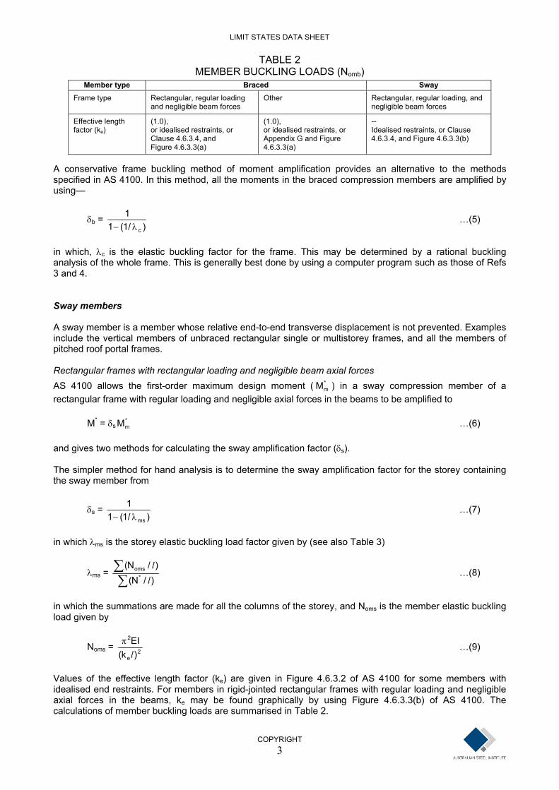
TABLE 2 MEMBER BUCKLING LOADS (Nomb)
Member type Braced Sway Frame type Rectangular, regular loading
and negligible beam forces Other Rectangular, regular loading, and
negligible beam forces
(1.0), Effective length factor (ke)
(1.0), -- or idealised restraints, or or idealised restraints, or
Appendix G and Figure 4.6.3.3(a)
Idealised restraints, or Clause 4.6.3.4, and Figure 4.6.3.3(b) Clause 4.6.3.4, and
Figure 4.6.3.3(a) A conservative frame buckling method of moment amplification provides an alternative to the methods specified in AS 4100. In this method, all the moments in the braced compression members are amplified by using—
)/1(11
cλ− δb = …(5)
in which, λc is the elastic buckling factor for the frame. This may be determined by a rational buckling analysis of the whole frame. This is generally best done by using a computer program such as those of Refs 3 and 4. Sway members A sway member is a member whose relative end-to-end transverse displacement is not prevented. Examples include the vertical members of unbraced rectangular single or multistorey frames, and all the members of pitched roof portal frames. Rectangular frames with rectangular loading and negligible beam axial forces AS 4100 allows the first-order maximum design moment ( ) in a sway compression member of a rectangular frame with regular loading and negligible axial forces in the beams to be amplified to
*mM
M* = δs …(6) *
mM and gives two methods for calculating the sway amplification factor (δs). The simpler method for hand analysis is to determine the sway amplification factor for the storey containing the sway member from
)/1(11
msλ− δs = …(7)
in which λms is the storey elastic buckling load factor given by (see also Table 3)
∑∑
)/N()/N(
*oms
ll
λms = …(8)
in which the summations are made for all the columns of the storey, and Noms is the member elastic buckling load given by
COPYRIGHT
Noms = 2e
2
)k(EIl
π …(9)
Values of the effective length factor (ke) are given in Figure 4.6.3.2 of AS 4100 for some members with idealised end restraints. For members in rigid-jointed rectangular frames with regular loading and negligible axial forces in the beams, ke may be found graphically by using Figure 4.6.3.3(b) of AS 4100. The calculations of member buckling loads are summarised in Table 2.
3

LIMIT STATES DATA SHEET
Example calculations of effective length factors and amplification factors for sway members in rectangular frames with negligible axial forces in the beams are given in Problems 4.6, 4.7 and 4.8 of Ref. 1. Two more general methods of moment amplification, which can also be applied to rectangular frames with negligible axial forces in the beams are discussed below.
TABLE 3 BUCKLING LOAD FACTORS (λ)
Type Used in Clause Buckling load factor From Clause
(λmb = Nomb / N*) 4.4.2.2 4.7.2.1 Braced member (λ by frame analysis)* (See Equation 5)* 4.7.2(b) Braced frame
λms = Σ (Noms / l) / Σ (N* / l) 4.4.2.3a(ii) 4.7.2.2 Sway storey (rect) (λc = (λms)min. , or 4.4.2.3(b)* 4.7.2.2 Sway frame (rect)
λc by frame analysis)* 4.7.2(b) λc by frame analysis 4.4.2.3(b) 4.7.2(b) Sway frame (non-rect)
* These conservative frame buckling methods provide alternatives to the methods specifically included in AS 4100. Other rectangular frames The first-order moments in other rectangular frames are generally amplified by using Equation 6 with the storey sway amplification factor calculated from
⎟⎟⎠
⎞⎜⎜⎝
⎛
∑∑− *
s
*s
VhN1
1Δ
δb = …(10)
This method is probably best used when the first-order elastic analysis results include the storey sway (Δs), the storey shears (V*), and the sway member axial compressions (N*). Example calculations of this method of determining amplification factors for sway members in rectangular frames are given in Problem 4.8 of Ref. 1. A more general frame buckling method of moment amplification which can also be applied to rectangular frames, with or without axial forces in the beams, is discussed below. Non-rectangular frames The most common examples of non-rectangular frames with sway members are pitched roof portal frames. AS 4100 allows the first-order maximum design moment ( ) in a sway member of a non-rectangular frame to be amplified using Equation 6 and sway amplification factor
*mM
)/1(11
cλ− δs = …(11)
in which λc is the elastic buckling load factor for the frame. The relationships between the member, storey, and frame buckling load factors are summarised in Table 3.
COPYRIGHT
4

LIMIT STATES DATA SHEET
COPYRIGHT
5
Approximate methods of determining the elastic buckling load factors of pitched roof portal frames are discussed in Ref. 5, which includes an example calculation. The elastic buckling load factor (λc) may also be determined by a rational buckling analysis of the whole frame. Generally this is best done by using a computer program such as those of Refs 3 and 4. This method can also be applied to rectangular frames, for which λc can be determined either by a rational buckling analysis of the whole frame, or from λc = (λms)min …(12) as given in Table 3. References 1 Bradford M.A., Bridge R.Q. and Trahair N.S. (1992), Worked examples for Steel Structures, Second
Edition, Australian Institute of Steel Construction, Sydney. 2 Trahair N.S. and Bradford M.A. (1991), The Behaviour and Design of Steel Structures, Revised
Second Edition, Chapman and Hall, London. 3 Hancock G.J. (1991), PRFSA User’s Manual, Centre for Advanced Structural Engineering, University
of Sydney. 4 Engineering Systems, (1990), MicroSTRAN-3D User’s Manual, Engineering Systems Pty Ltd.,
Sydney. 5 Trahair N.S. (1992), ‘Elastic In-Plane Buckling of Pitched Roof Portal Frames’, Limit States Data
Sheet AS 4100 DS04, Australian Institute of Steel Construction, Sydney and Standards Australia, Sydney.