as-cast az91d magnesium alloy properties: effects of...
TRANSCRIPT

Doctoral thesis
As-cast AZ91D Magnesium Alloy Properties: Effects of Microstructure and Temperature
Hoda Dini
Jönköping university School of Engineering Dissertation series No. 30. 2017

Doctoral Thesis As-cast AZ91D Magnesium Alloy Properties: Effects of Microstructure and Temperature Dissertation Series No.30 Copyright © 2017, Hoda Dini
Published and Distributed by School of Engineering, Jönköping University Department of Materials and Manufacturing SE-551 11 Jönköping, Sweden Tel: +4636101000 www.ju.se Printed by Inko AB, year2017 ISBN 978-91-87289-31-6


As-cast AZ91D magnesium alloy properties: Effects of microstructure and temperature
ABSTRACT
Today, there is an essential need for lightweight, energy-efficient, environmentally benign engineering systems, and this is the driving force behind the development of a wide range of structural and functional materials for energy generation, energy storage, propulsion, and transportation. These challenges have motivated the use of magnesium alloys for lightweight structural systems. Magnesium has a density of 1.74 g/cm3, which is almost 30% less than that of aluminium, one quarter of steel, and almost identical to polymers. The ease of recycling magnesium alloys as compared to polymers makes them environmentally attractive, but their poor mechanical performance is the primary reason for the limited adoption of these alloys for structural applications.
The Mg-Al-Zn alloy AZ91D exhibits an excellent combination of strength, die-castability, and corrosion resistance. However, its mechanical performance with regard to creep strength, for example, at evaluated temperatures is poor. Moreover, very little is known about the correlation between its mechanical properties and microstructural features. This thesis aims to provide new knowledge regarding the role played by microstructure in the mechanical performance of the magnesium alloy. The properties/performance of the material in relation to process parameters became of great interest during the investigation.
An exhaustive characterisation of the grain size, secondary dendrite arm spacing (SDAS) distribution, and fraction of Mg17Al12 was performed using optical and electron backscatter diffraction (EBSD). These microstructural parameters were correlated to the offset yield point (Rp0.2), fracture strength, and elongation to failure of the material. It was proposed that the intermetallic phase, Mg17Al12, plays an important role in determining the mechanical and physical properties of the alloy in a temperature range of room temperature to 190°C by forming a rigid network of intermetallic. The presence of this network was confirmed by studying the thermal expansion behaviour of samples of the alloy containing different amounts of Mg17Al12.
A physically based constitutive model with a wide validity range was successfully adapted to describe the flow stress behaviour of AZ91D with various microstructures. The temperature-dependent variables of the model correlated quite well with the underlying physics of the material. The model was validated through comparison with dislocation densities obtained using EBSD.
The influence of high-pressure die-cast parameters on the distortion and residual stress of the cast components was studied, as were distortion and residual stress in components after shot peening and painting. Interestingly, it was found that intensification pressure has a major effect on distortion and residual stresses, and that the temperature of the fixed half of the die had a slight influence on the component’s distortion and residual stress.
Keywords: Magnesium; Magnesium Alloy; AZ91D; High-Pressure Die-Casting; Mechanical Property; Microstructural Characterisation; Physical Modelling; Dislocations; Distortion; Residual Stress.


As-cast AZ91D magnesium alloy properties: Effects of microstructure and temperature
iii
SAMMANFATTNING
Numera finns det ett väsentligt behov av lätta, energieffektiva och miljövänliga tekniksystem. Detta behov är drivkraften för utveckling av ett brett utbud av material för energigenerering, energilagring, framdrivning och transport. Dessa utmaningar motiverade användningen av magnesiumlegeringar för lättviktskonstruktioner. Magnesium har en densitet på 1,74 g/cm3, vilket är ca 30% lägre än för aluminium, en fjärdedel av densiteten för stål och nästan i nivå med många polymerer. Då magnesiumlegeringar dessutom är lätta att återvinna, jämfört med polymerer, gör det dem miljömässigt attraktiva. Låga mekaniska egenskaper är den främsta orsaken till begränsad användning av dessa legeringar för lastbärande tillämpningar.
Mg-Al-Zn-legeringen AZ91D uppvisar en utmärkt kombination av styrka, gjutbarhet och korrosionsbeständighet. Dess mekaniska egenskaper vid förhöjd temperatur, som tex kryphållfasthet, är låga. Dessutom är korrelationen mellan mikrostruktur och mekaniska egenskaper oklar. Denna avhandling syftade till att ge ny kunskap om mikrostrukturens roll för magnesiumlegeringars mekaniska egenskaper. Slutligen var materialets egenskaper i förhållande till processparametrar vid tillverkningen av stort intresse.
En omfattande karaktärisering av kornstorleks-, sekundära dendritarmavstånds (SDAS)-fördelning och fraktion av Mg17Al12 utfördes med hjälp av optisk mikroskopering och diffraktion av bakåtspridda elektroner (EBSD). Mikrostrukturen korrelerades till sträckgränsen (Rp0.2), brottstyrkan och brottförlängningen. Det föreslogs att den intermetalliska fasen, Mg17Al12, spelar en viktig roll vid bestämning av legeringens mekaniska och fysikaliska egenskaper vid temperaturintervall från rumstemperatur upp till 190°C genom att bilda ett styvt nätverk av intermetaller. Uppkomsten av ett sådant nätverk stöddes genom en studie av den termiska expansionen av legeringen för olika fraktioner av Mg17Al12.
En fysikalisk konstitutiv modell med ett brett giltighetsområde användes framgångsrikt för att beskriva det plastiska flytbeteendet hos AZ91D för olika mikrostrukturer. De temperaturberoende variablerna i modellen korrelerade ganska väl med materialets underliggande fysik. Modellen validerades genom att jämföra dislokationstätheten som predikterades av modellen och den med EBSD uppmätta dislokationstätheten.
Påverkan av pressgjutningsparametrar på geometrisk tolerans och restspänning hos de gjutna komponenterna studerades. Vidare studerades geometrisk tolerans och restspänning av komponenter efter pening och målning. Intressant nog hade eftermatningsfasen en stor effekt på geometrisk tolerans och restspänningar. Dessutom hade temperaturen på den fasta formhalvan av verktyget även ett visst inflytande på komponentens geometriska tolerans och restspänning.
Nyckelord: Magnesium; Magnesiumlegering, AZ91D; Pressgjutna, Mekanisk Egenskap, Mikrostrukturkarakterisering, Fysikalisk Modellering; Flytspänning; Dislokationer; Geometrisk Tolerans; Restspänning

iv

As-cast AZ91D magnesium alloy properties: Effects of microstructure and temperature
v
ACKNOWLEDGEMENTS
I would like to express my deep respect and gratitude to Prof. Anders Jarfors, my primary supervisor, for his invaluable, fruitful, and constructive suggestions and guidance, which have enabled me to overcome all of the problems and difficulties that have arisen while carrying out the present work. He stayed with me and ensured that I was constantly motivated and stimulated. I feel fortunate to have enjoyed his support and involvement, and this is virtually impossible to express in words.
My appreciation also extends to my co-supervisor, Assistant Prof. Nils-Erik Andersson, who provided inspiration and helped me to understand the critical aspects of the work. The lessons learnt from him about considering problems from different perspectives were invaluable.
I would like to acknowledge Dr. Ehsan Ghassemali for his help with EBSD experiments and suggestions and advice. I am also thankful to Associate Prof. Ales Svoboda for his guidance with modelling. Thanks, are due to the current and former technical staff at the Jönköping University,
Department of Materials and Manufacturing, Toni Bogdanoff, Lars Johansson, Esbjörn Ollas, Peter Gunnarsson, and Jacob Steggo for their assistance. I thank Jörgen Bloom for his great assistance with experiments carried out at Husqvarna AB.
The industrial partner Husqvarna AB and Pär Guth are acknowledged for providing the necessary data and materials.
The Knowledge Foundation (KK-stiftelsen) is acknowledged for their financial support as part of the CompCast project (Dnr 20100280).
I sincerely thank the colleagues and friends at Jönköping University who made my doctoral studies more fun and joyful. All of the departmental conferences, lunches, after-work sessions, and fikas that we had played an important role in the writing of this thesis, although this might look contradictory.
I am grateful for the support and motivation provided by my family – especially my parents, Mohsen and Afsaneh, my sister, Nilufar, and my brother, Saber – and thank them for always believing in me. Last but definitely not least, I would like to thank Reza for his perspective and sense of balance, and for helping me to enjoy breaks from the thesis.
Jönköping 2017

vi

As-cast AZ91D magnesium alloy properties: Effects of microstructure and temperature
vii
SUPPLEMENTS
The following supplements constitute the basis of this thesis: Supplement I H. Dini, N. Andersson, A.E.W. Jarfors; ‘Effects of Microstructure on
Deformation Behaviour of AZ91D Cast Alloy’. TMS 2014, 143rd ANNUAL MEETING & EXHIBITION. February 16-20, San Diego, CA, USA.
Dini was the main author and performed the experimental work. Andersson and Jarfors contributed with supervision and advice on the experiments and methods of analysis. Supplement II H. Dini, N. Andersson, E. Ghassemali, A.E.W. Jarfors; ‘Microstructural
Scale Effects on Thermal Expansion Behaviour of Cast AZ91D’. Magnesium Technology 2015, pp. 361-365. TMS 2015. March 15-19, Orlando, FL, USA.
Dini was the main author and performed the experimental work. Andersson and Jarfors contributed with supervision and advice on the experiments and methods of analysis. Ghassemali assisted with the EBSD results. Supplement III H. Dini, N. Andersson, A.E.W. Jarfors; ‘Effect of Mg17Al12 Fraction on
Mechanical Properties of Mg-9%Al-1%Zn Cast Alloy’. Metals, 2016, Vol. 6.10, p. 251.
Dini was the main author and performed the experimental work. Andersson and Jarfors contributed with supervision and advice on the experiments and methods of analysis.
Supplement IV H. Dini, A. Svoboda, N. Andersson, E. Ghassemali, L. Lindgren, A.E.W. Jarfors; ‘Modeling the Deformation Behavior of As-Cast AZ1D Including the Effect of The Cast Microstructure’. Proceedings of PLASTICITY ’17: The Twenty Third International Conference on Plasticity, Damage, and Fracture (NEAT PRESS, P.O. Box 136, Fulton, Maryland 20759-0591, USA) (2017), pp. 37-39.
Dini was the main author and performed the experimental work. Svoboda and Lindgren contributed with adaptation and optimisation of the model. Ghassemali assisted with the EBSD results. Andersson and Jarfors contributed with supervision and advice on the experiments and methods of analysis.

viii
Supplement V H. Dini, A. Svoboda, N. Andersson, E. Ghassemali, L. Lindgren, A.E.W. Jarfors; ‘Optimization and Validation of a Dislocation Density Based Constitutive Model for As-Cast Mg-9%Al-1%Zn’; Materials Science and Engineering: A, Volume 710, 5 January 2018, Pages 17–26.
Dini was the main author and performed the experimental work. Svoboda and Lindegren contributed with adaptation and optimisation of the model. Ghassemali assisted with the EBSD results. Andersson and Jarfors contributed with supervision and advice on the experiments and methods of analysis.
Supplement VI H. Dini, N. Andersson, A.E.W. Jarfors; ‘Effect of Process Parameters on Distortion and Residual Stress of High-Pressure Die-Cast AZ91D Components’; International Journal of Metalcasting (2017), ISSN: 2163-3193, DOI: 10.1007/s40962-017-0186-z.
Dini was the main author and performed the experimental work. Andersson and Jarfors contributed with supervision and advice on the experiments and methods of analysis.
Supplement VII H. Dini, N. Andersson, A.E.W. Jarfors; ‘Effect of process parameters on distortion and residual stress in high pressure die cast AZ91D components after shot peening and painting’; submitted manuscript.
Dini was the main author and performed the experimental work. Andersson and Jarfors contributed with supervision and advice on the experiments and methods of analysis. The following article is not included in this thesis: Supplement VIII M. Zamani, H. Dini, A. Svoboda, L. Lindgren, S. Seifeddine, N. Andersson,
A.E.W. Jarfors; ‘A dislocation density based constitutive model for as-cast Al-Si alloys: Effect of temperature and microstructure’; International Journal of Mechanical Sciences 121(2017): 164-170.
Zamani was the main author. Dini, Svoboda, and Lindegren contributed with development and optimisation of the model. Seifeddine, Andersson, and Jarfors contributed with supervision and advice on the methods of analysis.

As-cast AZ91D magnesium alloy properties: Effects of microstructure and temperature
ix
TABLE OF CONTENTS
CHAPTER 1 INTRODUCTION ................................................................................................ 1
1.1 BACKGROUND 1
1.2 MAGNESIUM ALLOYS 2
1.3 MG-AL-BASED ALLOYS 3
1.4 HIGH-PRESSURE DIE-CASTING 6
1.5 DEFORMATION MECHANISMS OF MAGNESIUM ALLOYS 9
1.6 MECHANICAL PROPERTIES OF MG-AL ALLOYS 11
1.7 DEFORMATION MODELING OF MAGNESIUM ALLOYS 12
CHAPTER 2 RESEARCH APPROACH ................................................................................ 21
2.1 PURPOSE AND AIM 21
2.2 RESEARCH DESIGN 22
2.3 MATERIAL AND EXPERIMENTAL PROCEDURE 25
CHAPTER 3 SUMMARY OF RESULTS AND DISCUSSION ....................................... 33
3.1 CASTING AND MICROSTRUCTURAL SCALE 33
3.2 MECHANICAL PROPERTIES AND MICROSTRUCTURAL SCALE 36
3.3 THERMAL EXPANSION BEHAVIOR AND MICROSTRUCTURAL SCALE 42
3.4 MODELING THE PLASTIC FLOW OF AZ91D 46
3.5 EFFECT OF HPDC ON DISTORTION AND RESIDUAL STRESS 55
CHAPTER 4 CONCLUDING REMARKS ............................................................................ 65
CHAPTER 5 FUTURE WORK .................................................................................................. 67
REFERENCES ................................................................................................................................. 69
APPENDED PAPERS.................................................................................................................... 77

x

As-cast AZ91D magnesium alloy properties: Effects of microstructure and temperature
1
CHAPTER 1
INTRODUCTION
CHAPTER INTRODUCTION
This chapter commences with a background on magnesium cast alloys, with a special focus on the AZ91D alloy and its general microstructural features and mechanical properties. A constitutive model, which was based on the evolution of immobile dislocation and used to describe the plastic flow of the alloy, is introduced.
1.1 BACKGROUND
Weight-reduction efforts are being driven by higher fuel costs, the need for greater efficiency, and reductions in CO2 emissions for environmental reasons [1-3]. Countries such as Germany, the UK, France, the USA, South Korea, and Japan are currently undertaking major national research and development initiatives [1, 4-7]. At least half of Sweden's exports depend on the development of lightweight materials [8], and so it is essential that a national, concerted effort to promote lightweight solutions is made in order for growth in key strengths to occur.
The focus of lightweight solutions is on reducing weight through improved properties and new, innovative solutions [3]. Hence, studying the properties/performance of materials and the relationships between these and processing parameters and microstructures is of primary interest. Metallic materials such as aluminium and magnesium, as well as composites and sandwich materials, have tremendous potential in relation to the development of lightweight materials with regard to improving material properties and developing manufacturing processes and component solutions.
In recent decades, finding materials that are lighter than aluminium has become increasingly important, as have producing complex structures and reducing costs [9]. Magnesium is an attractive alternative in the fields of advanced materials for aircraft systems, the automotive industry, and hand-held tools – for use both today and in the future.
Casting is an inexpensive, low-emission manufacturing technique that facilitates the production of components in a wide range of sizes and with complex geometries, and thus plays a crucial role in the production of lightweight technologies. High-pressure die-casting is the preferred manufacturing process for the magnesium alloy components used by the automotive industry, as well as in numerous other applications, including the components used in hand-held tools [10].
In Europe, the increasing usage of magnesium as a lightweight structural material is being led by the Volkswagen Group, as well as Daimler, BMW, Ford, and Jaguar [3, 9, 11, 12]. At present, approximately 14 kg of magnesium is used in the VW Passat and Golf platforms, which utilise AZ91D for transmission casings, offering a 20-25% weight saving over aluminium [13]. For

2
Husqvarna AB, a Swedish outdoor power tool manufacturer, it is important to be able to manufacture products that are as light as possible and still deliver satisfying performance. Many of their products are carried by users on a daily basis, and so the company is always seeking new materials with high specific strength for use in both engines and cutting components. Today, Husqvarna AB uses AZ91D for applications such as crankcases.
Although magnesium castings are being used in a growing number of structural applications, the amount of research and development that has been carried out on these alloys is very small in comparison to investigations of aluminium alloys. The main challenge to the widespread usage of cast magnesium alloys as it comes to performance without weight increase requires improved strength at elevated temperatures [14].
This thesis is connected to the development of sustainable lightweight solutions for the future. Its overall goal is to communicate an improved understanding of the relationship between the microstructure and manufacturing processes of magnesium alloys, and to explain how this will affect the final product’s processability and properties.
This chapter provides general information about magnesium alloys and their manufacturing processes, microstructures, and properties. In the last section of this chapter, the physically based model that was adopted in this work to correlate the microstructural and mechanical properties of the material is introduced.
1.2 MAGNESIUM ALLOYS
Magnesium alloys have the lowest density (less than 1.8 g/cm3) of all structural metals, and their increased use in automobile and aircraft parts has resulted in increases in energy efficiency through weight saving [15]. Magnesium is also the eighth most abundant element on Earth, and is easy to machine and potentially recyclable [16]. Its poor creep properties above 120°C are the primary obstacle to the broader use of magnesium alloys in automotive systems [17]. Enhancing the creep resistance of magnesium alloys has therefore been the subject of various research projects, which have sought to explore alloy composition [18-20]. The most widely used alloying element is aluminium, which is relatively inexpensive and has a low density and strong strengthening effect on magnesium. Hence, most commercial magnesium alloys are based on the Mg-Al system, with small additions of other alloying elements such as zinc, manganese, silicon, and rare earth elements to meet certain application requirements.
Although wrought magnesium alloys have higher mechanical strength than as-cast ones, they exhibit higher mechanical anisotropy, which is detrimental to forming processes. Moreover, the processing of wrought magnesium alloys into their final shape is more complex [21]. Hence, magnesium components are generally produced by casting [22, 23], as this is the most cost-efficient process. However, the poor mechanical performance of as-cast magnesium alloys is a concern in relation to their applications, and is largely due to the presence of porosity and microstructural inhomogeneities such as variation in grain size and phase distribution [24-29]. Hence, attempts utilising both experimental [25-31] and modelling [25, 32-35] approaches have been made to relate microstructure to mechanical performance in magnesium casting. However, and despite these studies, a large scatter in data has been observed, which means that a significant effort is still required to establish a quantitative relationship between the microstructure and mechanical properties of magnesium alloys.

As-cast AZ91D magnesium alloy properties: Effects of microstructure and temperature
3
In conclusion, further work is required in order to i) understand the clear correlation between the microstructural features and mechanical behaviour of magnesium alloys and use a modelling tool to predict these behaviours; ii) optimise manufacturing techniques to improve the quality of cast magnesium parts.
1.3 MG-AL-BASED ALLOYS
Aluminium is alloyed with magnesium to increase its strength, castability, and corrosion resistance. The maximum solid solubility of aluminium in magnesium at 437°C is 12.7 wt% (Figure 1), decreasing to around 2% at room temperature (RT). Hence, an incoherent, coarse precipitate phase of the Mg17Al12 is formed following precipitation-hardening treatment [36].
To improve fluidity and room-temperature strength and reduce the corrosive effect of iron and nickel, zinc is often added to Mg-Al alloys. However, the addition of zinc in concentrations of greater than 1.0-1.5% to magnesium alloys consisting of 7-10% aluminium results in a hot cracking effect [36].
Manganese is another element that is alloyed with both Mg-Al and Mg-Al-Zn alloys to reduce impurities from iron and other heavy metals and turn them into Al-Mn-Fe intermetallic compounds, which may settle down during alloy production. The concentration of magnesium strongly depends on the aluminium concentration in the Mg-Al-Zn alloy, as the solubility of manganese in liquid magnesium sharply decreases with increasing aluminium content [36].
Figure 1. Mg-Al phase diagram [37].
4
AZ91D (9% aluminium, 1% zinc) is one of the most common alloys in the Mg-Al-Zn alloying system. The microstructure and phase transformation that takes place during the solidification of AZ91D have been studied [38-40]. It has been revealed that microstructure of as-cast AZ91D constituents of hypoeutectic Mg-Al solid solutions, eutectic Mg-Al supersaturated solid solutions, and Mg17Al12 phases. These phases were obtained under non-equilibrium solidification conditions.
Under equilibrium conditions, AZ91D should solidify with the formation of only hypoeutectic Mg-Al solid solution (Figure 1). However, the slow diffusion of aluminium under non-equilibrium solidification conditions leads to the formation of eutectic Mg17Al12 phases and an aluminium-rich eutectic Mg-Al solid solution [41].
During non-equilibrium solidification it is assumed that, at the interface of the liquid/solid, each phase has the chemical composition identified from the equilibrium phase diagram in Figure 1; although diffusion does not occur in the solid, the composition of the liquid is uniform due to convection [42].
The morphology of a eutectic structure formed under non-equilibrium cooling conditions is different to that of a typical eutectic morphology formed through eutectic solidification [43]. Here, a divorced eutectic structure is formed in place of the typical lamellar eutectic morphology [44].
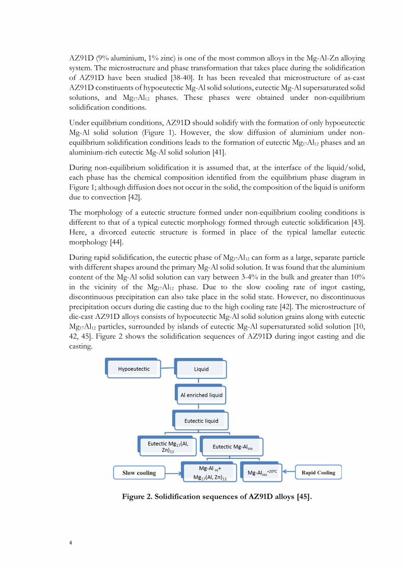
During rapid solidification, the eutectic phase of Mg17Al12 can form as a large, separate particle with different shapes around the primary Mg-Al solid solution. It was found that the aluminium content of the Mg-Al solid solution can vary between 3-4% in the bulk and greater than 10% in the vicinity of the Mg17Al12 phase. Due to the slow cooling rate of ingot casting, discontinuous precipitation can also take place in the solid state. However, no discontinuous precipitation occurs during die casting due to the high cooling rate [42]. The microstructure of die-cast AZ91D alloys consists of hypoeutectic Mg-Al solid solution grains along with eutectic Mg17Al12 particles, surrounded by islands of eutectic Mg-Al supersaturated solid solution [10, 42, 45]. Figure 2 shows the solidification sequences of AZ91D during ingot casting and die casting.
Figure 2. Solidification sequences of AZ91D alloys [45].

As-cast AZ91D magnesium alloy properties: Effects of microstructure and temperature
5
The solidification sequences during the ingot casting of AZ91D alloys are as follows: Solidification of hypoeutectic magnesium solid solution from molten liquids starts at 595°C, and is followed by the formation of the first Mg-Al solid solution crystals, which are approximately 1.5% aluminium. As the alloy cools, hypoeutectic Mg-Al solid solution crystals increase in size, with each layer of atoms that is added to the crystal surface being richer in aluminium than preceding ones. When a temperature of 470°C is reached (the point at which freezing would be complete, according to the equilibrium diagram) the crystals are approximately 1.5% aluminium at their centres and 9% on their surfaces. Thus, the average composition is somewhere between 1.5 and 9% aluminium, although freezing is not yet complete. Further cooling increases the size of the hypoeutectic magnesium solid solution crystals, and the chemical composition of the surfaces of the crystals reaches roughly 12% aluminium when the eutectic temperature of approximately 437°C is achieved. At this temperature, the growth of hypoeutectic magnesium solid solution is terminated, and the grains exhibit aluminium-rich and -poor regions [36]. Hence, the growth of Mg-Al solid solution is completed at 437°C, and as the liquid reaches eutectic temperature it solidifies as two phases: eutectic Mg-Al solid solution and Mg17Al12 intermetallic. Depending on the subsequent cooling rate of the solid state, the eutectic magnesium solid solution may experience a discontinuous decomposition through the formation of Mg17Al12 intermetallic in lamellar form due to decreasing aluminium solubility in Ma-Al solid solution, or remain as a supersaturated solid solution at RT due to the slow diffusion rate of aluminium in magnesium. Accordingly, cooling rate has an effect on grain size, secondary dendrite arm spacing (SDAS), and the fraction of Mg17Al12. Figure 3 shows the typical microstructure of AZ91D.
Figure 3. Microstructure of AZ91D.
Mg17Al12
Primary α
200μm

6
1.4 HIGH-PRESSURE DIE-CASTING
Die casting is an efficient manufacturing process that is used to mass produce components in a wide range of shapes with great accuracy and consistent replication. Die casting produces cast parts with smooth surfaces that do not require further machining.
In high-pressure die casting (HPDC), molten metal is injected under high pressure and at high velocity into a die to rapidly fill it. The die absorbs the stresses of the injection and dissipates the heat of the metal. The velocity and acceleration of the metal are controlled by a hydraulic system so as to optimise flow and the forces experienced by the metal as it fills the cavity and solidifies [46].
The variety of die-casting systems is the result of trade-offs in terms of the fluid flow of the metal. There are two primary types of die-casting process: cold and hot chamber.
Cold-chamber machines are preferred for casting alloys with higher melting points, such as aluminium, copper, and some ferrous alloys. This process separates the molten metal reservoir from the actuator for most of the process cycle (see Figure 4). Hot-chamber machines are used for alloys with low melting points (such as magnesium alloys), as the molten metal is held in a furnace containing a gooseneck chamber (see Figure 5). At the beginning of the cycle a piston is retracted, allowing the chamber and gooseneck to fill with molten metal. The piston is activated and the metal is plunged into cylinder and melt flows through the gooseneck and into the die through a spreader and gate.
The HPDC process cycle includes five main stages: (i) Filling of the runner and bringing the molten metal to the feeding gate at a low velocity in order to avoid turbulence. The velocity of the plunger in this stage is the ‘first-phase injection speed’. (ii) Filling of the casting cavity at very high velocity to avoid premature solidification at the gate. The velocity of the plunger in this stage is the ‘second-phase injection speed’. (iii) The solidification phase, with high cooling rates. (iv) High pressure is applied during the intensification stage to balance the solidification shrinkage and minimise the amount of air trapped inside the cast part. (v) The ejection phase, wherein the cast part is removed and the die halves are sprayed and repositioned so as to be ready to repeat the cycle. Figure 6 illustrates the various phases of a HPDC process based on the plunger’s travel and pressure over time.
Quality control in relation to the entire cycle is primarily conducted through the various process parameters, such as initial melt and die temperature, first- and second-phase injection speed, intensification pressure, phase duration, etc. Studying, characterising, and classifying the various die-casting parameters and their influence on the properties of cast objects is necessary in order to solve many of the problems that relate to magnesium casting and promoting its use in state-of-the-art industries.
One of the most common defects in HPDC components is porosity, which has an adverse effect on mechanical properties. Porosity in die castings can be caused by either entrapped gases or solidification shrinkage. It has been reported that high intensification pressure tends to reduce the porosity level, and that a slow first-phase injection speed in combination with a short plunger stroke generally results in less porosity [47].
The other defect in HPDC components is distortion (warping) of the casting. This usually occurs during the cooling phase due to the reduced cooling time of the process and high thermal gradient of the cast product. During solidification, the contraction of the casting is constrained by the die, which may result in residual stresses and complex spring back during the extraction of the product from the die. For more complex castings, non-uniform cooling conditions may create plastic strain that results in permanent distortion.

As-cast AZ91D magnesium alloy properties: Effects of microstructure and temperature
7
Moreover, residual stresses may arise and evolve as a result of a wide variety of post-treatment processes, such as shot peening and paint-bake cycles. Shot peening is regarded as an effective method of improving the fatigue strength of components by inducing compressive residual stress through plastic deformation of a surface. A surface in which tensile residual stress has been induced by the casting process will be more prone to fatigue failure than a surface that has experienced compressive residual stress.
On the other hand, if substantial residual stress exists in a casting this may cease at high temperatures, resulting in partial distortion. The distortion that can occur during the paint-bake cycle when the temperature of a component exceeds 200°C can lead to residual stress. As the temperature reached during paint-bake cycles exceeds those that have been shown to initiate creep behaviour in Mg-Al alloys, it is feasible that residual stresses present prior to a paint-bake cycle could cause dimensional changes in components.
Porosity in cast products is a well-studied phenomenon [48-52], and component distortion resulting from temperature gradients during cooling, shot peening, and paint-bake cycles remains a critical issue. A more nuanced understanding of residual stress distribution and the distortion pattern of magnesium cast parts could, through improved process control and better die design, reduce the deviation from design specifications that occurs, simultaneously improving productivity and reducing costs. Specifying the appropriate set of process parameters in order to create a high-quality HPDC product is a key concern for engineers and researchers.
Figure 4. Cold-chamber HPDC machine [46].

8
Figure 5. Hot-chamber HPDC machine [46].
Figure 6. Curves for (a) plunger travel and (b) plunger pressure against time, indicating the various phases of a HPDC process [46].

As-cast AZ91D magnesium alloy properties: Effects of microstructure and temperature
9
1.5 DEFORMATION MECHANISMS OF MAGNESIUM ALLOYS
According to the von Mises yield criterion [23], more than five independent slip systems are needed for metals to deform uniformly and without failure at grain boundaries. Magnesium alloys have a hexagonal closest packed (HCP) structure, and so a limited number of slip systems are available to accommodate plastic deformation. At RT, magnesium alloys have four independent slip systems, with the remaining deformation accommodated by twinning. However, additional slip systems become active at elevated temperatures, providing sufficient independent systems and thus improving ductility.
1.5.1 Role of slip in deformation
Figure 7 shows the slip planes (basal, prismatic, and pyramidal) of magnesium alloys [23, 53]. Slip occurs when a resolved shear stress on a slip plane reaches the critical value for that system. At RT, the critical resolved shear stress (CRSS) is much greater for a non-basal slip system than a basal slip system. Hence, magnesium can be deformed easily within its basal planes at RT. Only two independent slip systems exist along slip direction ⟨1120⟩ (see Table 1). Pyramidal ⟨𝑎𝑎⟩ slip produces shape change that is identical to that produced by combined basal slip and prismatic ⟨𝑎𝑎⟩ slip; here, the resulting number of independent slip systems in all three deformation modes is still four [23], and thus cannot accommodate deformation in direction ⟨𝑐𝑐⟩ in order to fulfil the von Mises criterion. Thus, other non-basal slip systems with a c-direction component (Table 1) should be activated [54], or the deformation should occur by twinning [53].
Figure 7. Unit cell and slip planes in magnesium [53]. At temperatures of above 200°C, the critical resolved shear stress for non-basal systems rapidly decreases, and the secondary 1100⟨1120⟩ prismatic and 1101⟨1120⟩ pyramidal slip systems (see Table 1) become active. The larger Burgers vectors of (𝑐𝑐 + 𝑎𝑎) and small pyramidal plane distance at RT make the activation of pyramidal slip systems quite difficult, but increasing the temperature facilitates this somewhat [54]. These additional slip planes explain the increasing ductility at elevated temperatures.

10
Table 1. Independent dislocation systems in HCP metals [53].
Direction Plane Notation Number of independent modes
⟨𝑎𝑎⟩ Basal 0002⟨1120⟩ 2 ⟨𝑎𝑎⟩ Prismatic 1100⟨1120⟩ 2 ⟨𝑎𝑎⟩ Pyramidal, 1st order 1101⟨1120⟩ 4
⟨𝑎𝑎⟩ + ⟨𝑐𝑐⟩ Pyramidal, 2nd order 1011⟨1123⟩ 4 ⟨𝑎𝑎⟩ + ⟨𝑐𝑐⟩ Pyramidal, 2nd order 2111⟨1123⟩ 4 ⟨𝑎𝑎⟩ + ⟨𝑐𝑐⟩ Pyramidal, 2nd order 1122⟨1123⟩ 4
1.5.2 Deformation by twinning
Twinning is an important deformation mechanism in HCP materials at RT, wherein a portion of the original crystal takes up a new orientation as a result of shearing, producing a mirror image of the parent crystal [55].
In HCP metals, tension or compression of the c axis, which results in elongation, or shortening of the c orientation, can activate twinning in the form of either extension or compression twinning. The plane 1012 has been identified as the extension twin plane in magnesium. The crystal structure of the twinning part is the mirror image of the initial crystal with respect to the twinning plane, and leads to a rotation of 86.3° of the basal planes. This rotation may activate a new set of deformation systems, resulting in an entirely different set of deformation systems than the initial crystal experienced. Compression twinning has been observed on the plane 1011. This twinning mode leads to a 56° difference with the initial basal planes. The deformation system that occurs after compression twinning can increase the resolved shear stress on the extension twinning system, and so extension twinning can occur inside the initial twin. This results in a 37o rotation with respect to the initial crystal basal planes, as part of a mechanism called ‘double twinning’. Figure 8 shows the rotation of basal planes due to twinning [56].

As-cast AZ91D magnesium alloy properties: Effects of microstructure and temperature
11
Figure 8. Schematic illustration of a) the initial material with crystallographic directions c and a1; , b) lenticular of tensile twin, c) compression twinning, d) double twinning [56].
1.6 MECHANICAL PROPERTIES OF MG-AL ALLOYS
As is discussed above, the microstructure of as-cast Mg-Al in its initial state consists of solid solution and Mg17Al12 phases. The Mg17Al12 phases precipitate finely at grain boundaries, increasing the strength of the material by suppressing basal slip [57]. These precipitated Mg17Al12 phases are perpendicular to the basal plane [58] (the main slip system of α-magnesium matrices) and make the dislocating movement more difficult, increasing the strength of the alloy [59].
The primary challenge in the application of Mg-Al-based alloys is their poor mechanical properties at high temperatures and, more particularly, low creep resistance at temperatures above 120°C. It has been found [10, 20, 60-62] that the low creep resistance of Mg-Al-based alloys is the result of the poor thermal stability of the Mg17Al12 phase. Zhu et al. [30] reported that Mg17Al12 precipitates tend to coarsen at elevated temperatures, thus losing their strengthening effect. Discontinuous precipitation can result in the grain boundary sliding at elevated temperatures. The Mg17Al12 phase at grain boundaries may decompose at elevated temperatures, increasing the aluminium content in these regions and thus causing failure [59]. Moreover, it has been reported that micro cracks may nucleate at the interface of Mg17Al12 and

12
the magnesium matrix due to the incompatible body-centred cubic (BCC) structure of Mg17Al12
and the HCP structure of the matrix. This leads to the alloy having limited ductility [59]. However, it has been reported that temperatures of lower than 120°C are insufficient to soften Mg17Al12 particles or weaken solid-solution hardening, and hence the contribution of grain-boundary sliding is negligible [63, 64].
Regev et al. [65-67] found that, for pressure die-cast alloys (with a grain size of 15 µm) and ingot-cast alloys (with a grain size of 300 µm) in a temperature range of 70-200°C, low stress creep deformation is dominated by grain-boundary sliding. However, at higher stress levels (
310E
−>σ ), dislocation climb becomes the governing creep mechanism. The deformation
behaviour of AZ91D at stress levels exceeding that which is required for creep behaviour and relatively low temperatures has not been extensively studied. Under these conditions, diffusivity is limited and the main deformation mechanism is dislocation glide [68].
Moreover, changing the grain size influences the deformation map of the material [68]. Although the mechanical behaviour of Mg-Al produced by die casting has been extensively investigated and discussed [65, 66, 69-71], several studies [65, 70-74] have shown that alloys of similar composition produced using different cooling rates or technologies can exhibit markedly differing behaviour, due in particular to microstructural features such as volume fraction, distribution, and coarseness of Mg17Al12, α grains, and aluminium in the solid solution. However, to the best of the author’s knowledge, no correlation between microstructural features and mechanical behaviour has been clearly established for the AZ91D cast alloy. This knowledge is essential for selecting manufacturing techniques. Moreover, a detailed description of the alloy’s material behaviour across a wide range of temperatures and strain rates is crucial for simulating the deformation process. The use of physically-based models that are capable of correlating microstructural features to mechanical responses is the optimal means of accomplishing this [75]. The physically-based model that has been used to describe the plastic flow of the AZ91D alloy is introduced in the following section.
1.7 DEFORMATION MODELLING OF MAGNESIUM ALLOYS
Constitutive models that adequately represent the deformation behaviour of engineering materials under a combination of thermal and mechanical loading are crucial for obtaining accurate results when simulating manufacturing processes and service applications. These models are mathematical descriptions of physical phenomena, and so various modelling approaches exist.
The deformation behaviour of metals is commonly represented by an empirical relationship, seen largely in terms of the power law of strain and strain rate [76-78]. Such approaches are generally lacking in predictive capabilities beyond the derived range of experimental conditions at which they were curve-fitted. Models that are related to the underlying physics of deformation are therefore preferable. The advantage of using physically-based models is an expected larger domain of validity, as these models are able to predict values outside of the range of experimental data used for calibration, provided the deformation mechanisms included in the models describe the dominant deformation behaviour correctly [79].
The physical model presented in the following section includes a coupled set of evolution equations for internal state variables, dislocation density, and vacancy concentration.

As-cast AZ91D magnesium alloy properties: Effects of microstructure and temperature
13
Dislocation density is the amount (length) of dislocations for a representative volume element, divided by its volume. The model considers two different dislocation densities; mobile and immobile. Changes in the density of immobile dislocation are related to slip systems and thermally activated annihilation as a result of dislocation climb. The immobilisation rate of mobile dislocations is a function of microstructure, strain rate, and temperature. The recovery process occurs with climb [80] and glide of dislocations [81]. The diffusion of vacancies, which usually takes place at elevated temperatures, is a dominant factor in the recovery process of dislocations. The high concentration of vacancies near to grain boundaries enhances creep behaviour, controlled by dislocation glide and climb processes [82]. These internal state variables are used instead of accumulated effective plastic strain, which is commonly used in phenomenological models.
1.7.1 Modelling of flow stress
Flow stress consists of i) a component relating to long-range barriers, 𝜎𝜎𝐺𝐺, that cannot be assisted by thermal energy and ii) a component relating to short-range barriers, 𝜎𝜎∗, that is thermally activated. Hence, flow stress in Eq. 1 is defined as the combination of the components of resistance to the motion of dislocations [83-85].
∗+= σσσ Gy (1)
Long-range flow stress contribution is related to the interaction of immobile dislocations in substructures and can be written as [83]:
iGbmG ρασ = (2)
where m is the Taylor orientation factor, 𝛼𝛼 is a proportionality factor, and 𝜌𝜌𝑖𝑖 is the immobile dislocation density. The shear modulus,G , can be computed from the Young’s modulus, E , and Poisson ratio, υ , as
)1(2 υ+=
EG (3)
The short-range term in Eq. 1 is the thermally activated flow stress component. It is the stress needed for a dislocation to overcome short-range obstacles and move through the lattice. The total transient time taken by a dislocation to move between two obstacles consists of a waiting time and a travel time. A moving dislocation has a waiting time in front of an obstacle before it is able to overcome the obstacle and move to the next one. Travel time is short compared to waiting time, and is here assumed to be negligible. Waiting time is the inverse of the frequency
14
of the successful jumps to overcome obstacles. This frequency is related to the probability, defined by the Boltzmann law of energy distribution, that the dislocation has an energy that exceeds the needed activation energy to overcome the obstacles. Waiting time and thereby average velocity are assumed to depend on the Gibbs free energy of activation, G∆ , for cutting or by-passing obstacles [86] and temperature, T. Average velocity is defined as:
−=
kTΔG
aΛυν exp (4)
where Λ is the mean free path, υa is the attempt frequency, G∆ is the activation energy, k is the Boltzmann constant, and T is the temperature in Kelvin. Dislocation density and velocity are related to plastic strain rate via the Orowan equation [87]:
m
bmp νρε = (5)
where is the average velocity of mobile dislocations with a density of ρm,. The relationship described by Eq. 5 can be written as:
∆−
Λ=
kTG
mabmp exp
νρε (6)
The motion of dislocations is facilitated by thermal energy. If the stress is insufficient to drive a dislocation past a barrier with activation energy, G∆ , the probability that a dislocation will ‘jump over’ the barrier increases with increased temperature. Different shapes of barrier energy distribution result in different constitutive equations. A generalised equation for these shapes was proposed by Kocks et al. [88] with two parameters – p and q:
qp
athFG
∗−∆=∆
σσ1 (7)
Here, F∆ is the total free energy required for a dislocation to overcome the lattice resistance or obstacles. σath is the athermal flow strength that must be exceeded in order to move dislocations across the lattice without the aid of thermal energy. The exponents 0 < p ≤ 1 and 0 < q ≤ 2 are related to the shape of energy barriers. The pre-exponential term in Eq. 6, which is approximated following Frost and Ashby [86] to be constant, is expressed as:
ν

As-cast AZ91D magnesium alloy properties: Effects of microstructure and temperature
15
mabm
refνρ
εΛ
= (8)
where refε is the reference strain rate. Combining Eqs. (6), (7), and (8) yields:
∗−
∆−=
qp
athkTF
refp
σσεε 1exp (9)
Here, ΔF = Δf0Gb3is the activation energy necessary to overcome lattice resistance in the absence of any external force, and σath = τ0G is shear strength in the absence of thermal energy. Guidelines regarding Δf0 and τ0 are given in Table 2 [86], where L is the mean spacing of the obstacles, precipitates, or solutes.
Table 2. Activation energy factor and shear strength of different obstacles [86]. Obstacle Strength 𝜟𝜟𝜟𝜟𝟎𝟎 𝝉𝝉𝟎𝟎 Example
Strong 2 >𝑏𝑏𝐿𝐿
Strong precipitates
Medium 0.2-1.0 ≈𝑏𝑏𝐿𝐿
Weak precipitates
Weak < 0.2 ≪𝑏𝑏𝐿𝐿
Lattice Resistance
Accordingly, the short-range stress component in Eq. 1 as a function of effective plastic strain rate can be derived as [88-90]:
pq
pref
GbfkTG
11
30
0 ln1
∆−=∗
εε
τσ
(10)

16
1.7.2 Evolution of immobile dislocation density
The equation for flow stress in Eq. 1 requires evolution equations for internal state variables, which are dislocation density and vacancy concentration. Mobile dislocation density is assumed to be much smaller than its immobile counterpart [91, 92]. The evolution of immobile dislocation density is expressed in two terms; hardening (+) and recovery (-) [93]:
)()( −++= iii ρρρ (11)
Hardening processes
Mobile dislocations move over a mean free path, Λ, before they are immobilised or annihilated. Immobile dislocation density is assumed to increase proportionally to plastic strain rate, which is related to the density of mobile dislocations, shown in Eq. 5, and inversely to the mean free path:
pbm
i ερ Λ
=+ 1)( (12)
where m is the Taylor orientation factor. The mean free path can be related to SDAS ( 2λ ) in cast alloys and dislocation subcell or subgrain diameter (s) as:
sλΛ1
2
11+= (13)
The effect of grain size on flow stress, known as the Hall-Petch relation, is accounted for via this term. The formation and evolution of subcells is related to immobile dislocation density by the parameter Kc [94]:
iρcKs 1
= (14)

As-cast AZ91D magnesium alloy properties: Effects of microstructure and temperature
17
Recovery processes
Dislocation density may be reduced by different processes. Recovery, remobilisation, and/or annihilation of dislocations are proportional to current dislocation density and controlled by dislocation climb and glide. Recovery by dislocation glide is described by [88, 95]
pεiΩρ)(i,glideρ =− (15)
where 𝛺𝛺 is a recovery function that is dependent on temperature. This model accommodates only dynamic recovery due to strain rate. Static recovery as controlled by diffusion climb is assumed to be [96]
−=− 223
2lim eqρiρkTGb
eqνc
νcνDγc)(
bi,cρ (16)
where υc and eqcυ are current and equilibrium vacancy concentrations, respectively, and cγ is a material coefficient related to stacking-fault energy. The dislocation density decreases towards an equilibrium value of
eqρ . The self-diffusion coefficient is given according to Reed-Hill and Abbaschian [97]:
kTvQ
evDkTvfQvmQ
ekvfΔSvmΔS
eaυavD−
=
+−
+
= 02 (17)
where ΔSvm is the increase in entropy due to motion of vacancy, ΔSvf is the increase in entropy when forming a vacancy, Qvm is the energy barrier for vacancy motion, and Qvf is the activation energy for vacancy formation.
1.7.3 Evolution of excess vacancy concentration
Solving Eq. 16 requires the vacancy concentration to be calculated. The generation and motion of vacancies are coupled with the recovery of dislocations and diffuse solute atoms. The model presented here is only concerned with mono-vacancies. When a crystal is retained for a sufficient time and at a given temperature, an equilibrium level of vacancies is reached. Deforming the material or changing the temperature generates excess vacancies. The effect of excess vacancies on diffusion can be expressed as [98]

18
−
+−
+=−= eq
vcvcgsvmDpε
b
Ω
b
jcς
vfQ
byσχeqvcvcex
vc2
1210
24 (18)
Stress, yσ , is equal to the flow stress that occurs during plastic deformation, the factor pyεχσ
is the fraction of the mechanical work required for vacancy formation, vfQ is the activation energy for forming a vacancy, 0Ω is the atomic volume, and jc is the concentration of thermal jogs. The parameter ς describes the neutralising effect of a vacancy emitting and absorbing jogs, eq
vc is the equilibrium concentration of vacancies at a given temperature, vc is the non-equilibrium vacancy concentration, and Dvm is vacancy migration. The equilibrium concentration of vacancies at a given temperature is [97, 99]
−
=
kTvfQ
kvfΔS
eqvc expexp (19)
The rate of change in the vacancy equilibrium concentration is related only to temperature change:
TkT
vfQeqvceq
vc
=
2 (20)
Details of the model for vacancies and diffusion are to be found in Militzer et al. [98] and Lindgren et al. [93].
1.7.4 Stress update and optimisation of the model
A radial return operator for the integration of constitutive equations has been used to update flow stress [100, 101]. Computing the increment of effective plastic strain, which fulfils the consistency condition, requires calculating the yield stress and hardening modulus for the current iteration of the plastic strain and internal state variables. The evolution of the internal state variables is governed by the coupled differential equations. The rate of total change in immobile dislocation density is derived through Eq. 21, and the rate of change in vacancy concentration is derived through Eq. 22:

As-cast AZ91D magnesium alloy properties: Effects of microstructure and temperature
19
−−
−= 223
21eqρiρkT
Gbeqvc
vcvDγcpεiΩρ
Λbm
iρ (21)
( ) ( ) TTQ
cccg1
s1D
bb4c
Qc 2
vfeqv
eqvv22vm
p02
j*G
vf
0v
+−
+−
++= εΩςσσΩχ (22)
Once the dislocation density and vacancy concentration are known, the hardening modulus and flow stress can be evaluated. During the increment iteration, the plastic strain rate is assumed to be constant. The hardening modulus in the incremental form is given by
plplvc
vci
pli
i
Gpld
ydH
ε
σ
ε
ρ
ε
ρ
ρ
σ
ε
σ
∂
∂+
∂
∂
∂
∂+
∂
∂
∂
∂==′
* (23)
The parameters for the model were obtained using an in-house MATLAB-based toolbox. Then, a physically based model to describe the evolution of the flow stress of the alloy based on temperature range, strains, and strain rates was developed. One set of experiments was used for model calibration, and another, more complex one, was used for the validation of the former.

20

As-cast AZ91D magnesium alloy properties: Effects of microstructure and temperature
21
CHAPTER 2
RESEARCH APPROACH
CHAPTER INTRODUCTION
This chapter describes the research methodology used in this thesis. The purpose and aim of the work are described, and descriptions of materials and experimental procedures are given.
2.1 PURPOSE AND AIM
Lightweight structures are increasingly in demand in a wide range of engineering applications, including the automobile, aerospace, and electronics industries. Moreover, in hand-held tools such as chainsaws, weight is more important than power to the customer. Due to their low densities, good castability, and various beneficial material properties, magnesium alloys are attractive choices for lightweight structural applications. Husqvarna AB currently uses AZ91D alloys for applications such as the crankcases of engines, wherein the material is exposed to moderate temperatures and loads. To further reduce overall weight, it is necessary to reduce the load on the crankshaft, where the component experiences high stresses. However, in this kind of application the component is exposed to temperatures above those that magnesium alloys can be used at. To provide new insights into the development and applications of magnesium alloys, their properties and performance in relation to processing parameters and their microstructures were studied. The research presented in this thesis concentrates specially on determining the mechanical performance of AZ91D alloy. The reasons of this focus have been detailed in pervious chapter and the purposes of the study are summarized below:
The purpose of this work is twofold:
i) To better understand mechanical performance during use:
This work constitutes an attempt to correlate the microstructural features (e.g. SDAS, grain size, and intermetallic phases) and mechanical/physical behaviour of as-cast AZ91D alloys at temperatures ranging from RT to 190ºC. This was followed by adaptation and optimisation of a physically based model which enables the flow stress behaviour of the alloy to be predicted across different microstructures. As a benefit, the optimised model parameters can be employed in finite element modelling simulations of the behaviour of cast components at different working temperatures.
ii) To better understand the mechanical performance during processes:
The effects of HPDC process parameters on the distortion and residual stress of AZ91D components have been studied, as have the effects of shot peening and paint-bake cycles in relation to process parameters.
22
2.2 RESEARCH DESIGN 2.2.1 Research approach
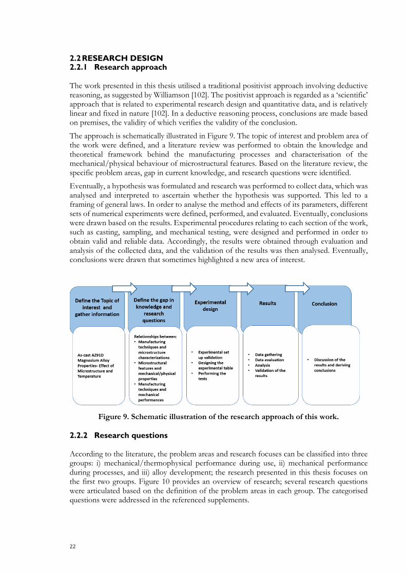
The work presented in this thesis utilised a traditional positivist approach involving deductive reasoning, as suggested by Williamson [102]. The positivist approach is regarded as a ‘scientific’ approach that is related to experimental research design and quantitative data, and is relatively linear and fixed in nature [102]. In a deductive reasoning process, conclusions are made based on premises, the validity of which verifies the validity of the conclusion.
The approach is schematically illustrated in Figure 9. The topic of interest and problem area of the work were defined, and a literature review was performed to obtain the knowledge and theoretical framework behind the manufacturing processes and characterisation of the mechanical/physical behaviour of microstructural features. Based on the literature review, the specific problem areas, gap in current knowledge, and research questions were identified.
Eventually, a hypothesis was formulated and research was performed to collect data, which was analysed and interpreted to ascertain whether the hypothesis was supported. This led to a framing of general laws. In order to analyse the method and effects of its parameters, different sets of numerical experiments were defined, performed, and evaluated. Eventually, conclusions were drawn based on the results. Experimental procedures relating to each section of the work, such as casting, sampling, and mechanical testing, were designed and performed in order to obtain valid and reliable data. Accordingly, the results were obtained through evaluation and analysis of the collected data, and the validation of the results was then analysed. Eventually, conclusions were drawn that sometimes highlighted a new area of interest.
Figure 9. Schematic illustration of the research approach of this work.
2.2.2 Research questions
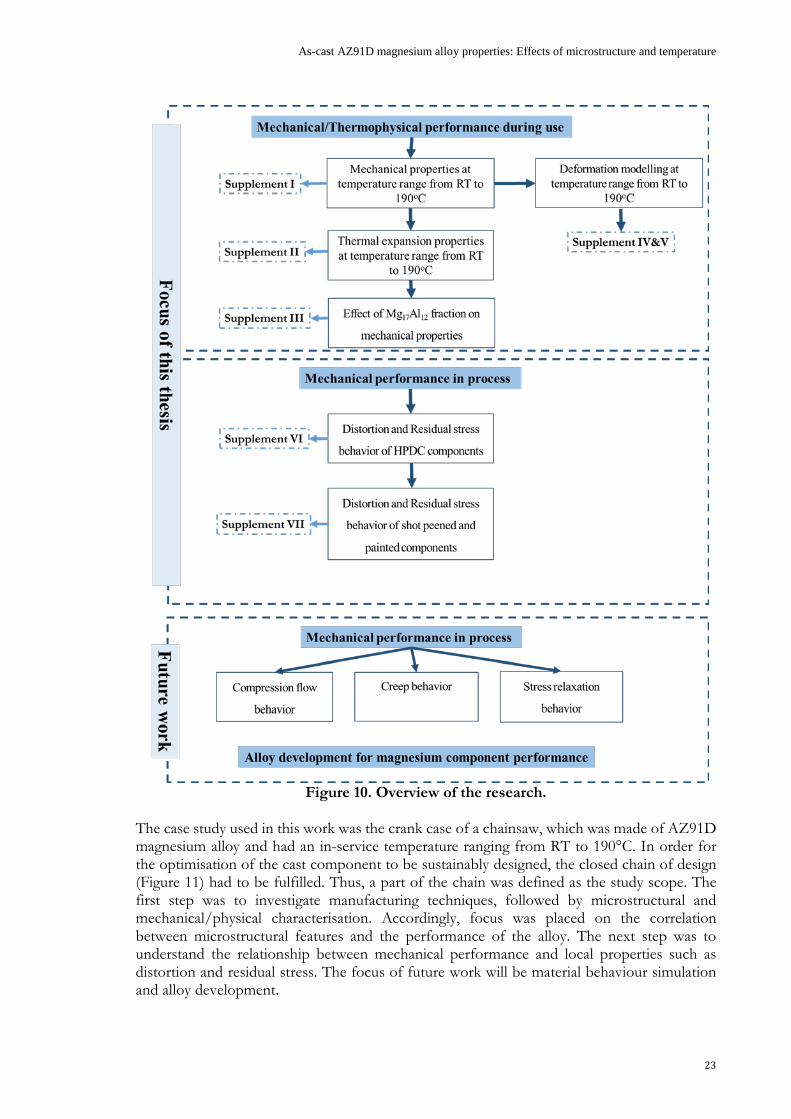
According to the literature, the problem areas and research focuses can be classified into three groups: i) mechanical/thermophysical performance during use, ii) mechanical performance during processes, and iii) alloy development; the research presented in this thesis focuses on the first two groups. Figure 10 provides an overview of research; several research questions were articulated based on the definition of the problem areas in each group. The categorised questions were addressed in the referenced supplements.
As-cast AZ91D magnesium alloy properties: Effects of microstructure and temperature
23
Figure 10. Overview of the research.
The case study used in this work was the crank case of a chainsaw, which was made of AZ91D magnesium alloy and had an in-service temperature ranging from RT to 190°C. In order for the optimisation of the cast component to be sustainably designed, the closed chain of design (Figure 11) had to be fulfilled. Thus, a part of the chain was defined as the study scope. The first step was to investigate manufacturing techniques, followed by microstructural and mechanical/physical characterisation. Accordingly, focus was placed on the correlation between microstructural features and the performance of the alloy. The next step was to understand the relationship between mechanical performance and local properties such as distortion and residual stress. The focus of future work will be material behaviour simulation and alloy development.

24
Figure 11. The closed chain of design-optimisation sustainability.
The primary research questions are listed below, and addressed in the indicated supplements: Mechanical/thermophysical performance during use
1. What is the relationship between manufacturing techniques and microstructural features? (Supplements I & III)
2. What are the effects of microstructure (size, morphology, and distribution of different phases) on the mechanical behaviour of as-cast AZ91D? (Supplements I & III)
3. What is the relationship between microstructural features and the thermomechanical properties of the alloy? (Supplement II)
4. Is it possible to model the flow-stress behaviour of as-cast AZ91D at different temperature ranges based on the underlying physics of the material? (Supplements IV& V)
5. Does the model have sufficient validity to predict the behaviour of different as-cast microstructures? (Supplements IV& V)
Mechanical performance during processes:
1. What are the effects of HPDC process parameters on the distortion and residual stress responses of cast components? (Supplement VI)
2. What is the effect of post treatments such as shot peening and paint-bake cycles on distortion and residual stresses in cast components? (Supplement VII)
3. Is there any relationship between distortion and residual stresses in HPDC components? (Supplements VI & VII)

As-cast AZ91D magnesium alloy properties: Effects of microstructure and temperature
25
2.3 MATERIAL AND EXPERIMENTAL PROCEDURE 2.3.1 Alloy composition
The chemical composition of the AZ91D samples used in the experiments was determined using an optical emission spectroscopy (OES; SpectroMaxCCD LMXM3, SPECTRO Analytical Instruments, Germany) metal analyser. Table 3 gives the average alloy composition from three OES analyses.
Table 3. Chemical composition of the AZ91D samples used in the experiments (wt%), established using OES. Mg Al Zn Mn Fe Ni Cu Si
Balance 8.5 ±0.2
0.67 ±0.3
0.25 ±0.1
0.0023 ±0.01
0.0017 ±0.005
0.021 ±0.03
0.017 ±0.1
2.3.2 Directional casting technique
Commercial ingots of AZ91D were melted in mild steel crucibles using a vacuum filling process and gas protection in the form of a mixture of dry air and 0.5% SF6 to minimise the presence of oxide films and inclusions during casting (see Figure 12). The melt was sucked up to the 1000 mm mild steel rods, which were cut into 170 mm long bars and re-melted in a Bridgman furnace device under protective gas (0.5% SF6 and dry air). The melt was maintained at 670°C until fully melted at 30 minutes. The cooling rate of the specimen was controlled by the drawing rate of the furnace. Furnace pull rates in the range of 0.3-6mm/s were employed, depending on the desired scale of the microstructure, and resulted in microstructures with average SDAS values of 4.2-25 µm. A schematic depiction of the Bridgman furnace device used in the experiments is shown in Figure 13.
Figure 12. Schematic of the vacuum filling device used in the experiments.

26
Figure 13. Schematic of the Bridgman furnace device used in the experiments.
2.3.3 Component-casting technique
The case study was a chainsaw engine crank (Figure 14). The components were produced using a cold-chamber HPDC machine (Buhler SC-D42 with 4000 kN locking force), and the protective gas was a mixture of 0.5% SO2 and dry air.
Figure 14. Configuration of the component.
The effects of process parameters and their interactions with component characteristics and performance were studied by investigating four HPDC parameters: first-phase injection speed (A in Table 4), the temperature difference between the two die halves through varying the temperature of the fixed half of the die (B), cooling time (C), and intensification pressure (D). Other process parameters were kept constant. The choice to omit second-phase injection speed was made due to the fact that the dwell time in the shot sleeve is in the order of 70 times longer than the duration of the second phase, resulting in temperature loss during the process being dominated by the shot chamber dwell time. The interfacial heat flux was in the order of 2 MW/m2 in the shot sleeve [103] and 6 MW/m2 in the die cavity [104] during filling, and so shot sleeve dwell time is the dominant parameter as regards the temperature of the final part during processes. The minimum and maximum levels of HPDC parameters are given in Table 4. The interactions between these parameters were also studied. The DesignExpert™ software package (Stat-Ease) was used for the design of experiments (DOE) and, in order to have an effective experimental design, a quadratic response surface method was used with a D-optimal
Protection gasFurnace moving upward
Heating zone
Water inlet
Water outlet
Cooling zone
Heating element
Water outletWater inlet

As-cast AZ91D magnesium alloy properties: Effects of microstructure and temperature
27
approach, with three replications and three runs performed in order to determine the lack of fit. Regression analysis and analysis of variance (ANOVA) were also employed. Table 4. HPDC parameters and their minimum and maximum levels, together with the average of the reference-level parameters for the reference cast sample [105].
Symbol HPDC parameter Unit Min. level Max. level Ref. level A First-phase injection speed m/s 1.5 4.5 1.5
B Temperature of fixed half of the die °C 100 220 220
C Cooling time s 5 15 7 D Intensification pressure Bar 450 1100 824
2.3.4 Shot peening
Shot peening was performed by Husqvarna AB using their recommended peening procedure for improving the surface integrity of the components. Aluminium rods were used in the peening process.
2.3.5 Paint-bake cycle
Real paint was not applied, but the components went through paint-bake treatment. The paint application cycle involved a series of three-step processes, the first of which involved cleaning the components with water at a temperature of 40°C for 8 minutes. During the second step, the components were dried at 100°C for 20 minutes and cooled in the air. The third step was curing at 200°C for 30 minutes.
2.3.6 Tensile testing
Tensile bars were prepared according to ASTM B577 [106]. The geometry of the test specimen is shown in Figure 15. A ZWICK-ROLL™ Z100 laser extensometer was used to measure strain. Tensile tests were carried out between RT and 190°C at strain rates ranging from 10-4 to 10-1 1/s. In order to understand the relationship between microstructure and tensile performance, a table of values was created, wherein the data from samples with different microstructures that had been tensile tested under various conditions was input, using the DesignExpert™ software. The minimum and maximum levels of the tensile test parameters are shown in Table 5. For each tensile test, at least four repetitions were considered to have statistical significance for the results. To facilitate effective optimisation, the number of data points was reduced using a specially devised MATLABTM code. Flow-stress curves, ultimate tensile strength (Rm), stress at 0.2% offset strain (Rp0.2), and strain at which failure occurs (𝜀𝜀𝑓𝑓) were derived from this process.

28
Figure 15. The geometry of the tensile test specimen [106].
Table 5. Minimum and maximum values of the parameters of the tensile tests. Parameter Unit Min. level Max. level Furnace pulling rate m/s 0.3 6 Temperature °C RT 190 Strain rate s-1 10-1 10-4
2.3.7 Component distortion measurements
Distortion values were measured using the standard in-house quality-assurance tool (Figure 16), and compared to the dimensions of the actual HPDC components and the design component at the reference points D1-D5 (see Figure 17). The measured direction was along the normal vector of the surface, and the measurement yielded a (positive or negative) value that signified deviation from the zero plane.
Figure 16. The standard in-house quality-assurance tool used to measure distortion values. D1, D2, D3, D4 and D5 are the 5 reference points. [105].

As-cast AZ91D magnesium alloy properties: Effects of microstructure and temperature
29
Figure 17. Schematic of the component and points at which distortion measurements were taken (D1-D5) [105].
2.3.8 Residual stress measurements
The Prism hole-drilling system (Stresstech Group) was used to measure residual stresses. The hole-drilling technique involves drilling a hole in the component and measuring the resulting strain in the area near the hole, and is based on the fact that when a stressed material is removed from its surroundings, the equilibrium of the surrounding material must readjust its stress state to attain a new equilibrium. In the conventional technique using strain gauges, surface distortion is measured as a change in electrical resistance [107], whereas the Prism system measures surface distortion using laser light (electronic speckle pattern interferometry) [108] (see Figure 18). Images taken before the drilling are compared to ones taken after each increment, and every condition is depicted by a set of four images, each taken with the reference beam phase-shifted by a different amount: 0°, 90°, 180°, and 270°. The reference beam interferes with the object beam on the CCD, allowing the displacement of the measured surface to be made visible as phase shifts. Illumination and observation directions can be adjusted by the user to accommodate a variety of measurement conditions, and so the direction of the measurement can vary. Data analysis included all of the pixels in a ring-shaped region around the hole, described by the inner and outer integration radius (the inner radius was twice that of the hole’s radius, and the outer radius was four times that of the hole). The area immediately adjacent to the edge did not provide useful information because the drilling process disturbs this part of the surface. An unwrapping algorithm was used to produce the displacement map for each of the three variables of the planar stress state and, together with the elastic material parameters, Young’s modulus, and Poisson’s ratio, this led to the generation of the stress values. The maximum useful hole depth was dependent on hole diameter. The numerical models developed for the Prism system support drilling of 0.1 < h/d < 0.6 mm. End mills with a 0.8 mm diameter were used in this study.

30
Figure 18. Schematic of the Prism system [108].
Residual stresses were measured at three locations; R1, R2, and R3 (Figure 19). These are the critical points that have exhibited failure (creep and/or fatigue) issues during operation. The maximum residual stress value at any depth was adopted as the residual stress value of the whole product in this process. The drilling rig was programmed to reach a final depth of 0.5 mm via 14 equidistant steps, with a drilling feed rate of 0.05 mm/s. After each drilling step, drilling was stopped for approximately 60 seconds and the first set of images was captured; a second was taken roughly 30 seconds later. For all measurements, the alpha rotation angles of the light source and the CCD were 50° and 30°, respectively. Stresses were calculated using a Poisson’s ratio value of 0.3 and Young’s modulus of 45,000 MPa.
Figure 19- Schematic of the component and points at which residual stress measurements were taken (R1-R3) [105].

As-cast AZ91D magnesium alloy properties: Effects of microstructure and temperature
31
Signed von Mises (SVM) stress represents the sign (positive or negative) of the absolute maximum principal stress, including the influence of tension and compression on the effective stress. The SVM stress was obtained using
vmsvm Isign σσ ⋅= )( 1 (24)
where vmσ is the Von Mises stress and zyxI σσσ ++=1
2.3.9 Microstructural characterisation
Samples were prepared following standard procedures for microstructural characterisation [109]. Sectioned samples were etched at RT using 10 ml HF (48%) for 1-2 s to etch the Mg17Al12 phase [110]. An optical microscope (Olympus Corporation, Japan) was used for qualitative microstructural studies. It should be noted that all optical characterisation involved at least five images per sample to assure internal validity. SDAS was quantified by identifying and measuring small groups of well-defined secondary dendritic arms on the optical micrographs. The value of SDAS was then practically determined using SDAS = L/n, where L is the length of the line drawn from edge to edge of the measured arms, and n is the number of dendritic arms. The mean values of SDAS for each sample are averages of more than 50 dendrite arms. The area fraction of phases was measured using Olympus Stream image analysis software (v. 1.8), based on image contrast. Following ASM Specialty Handbook: Magnesium and Magnesium Alloys [111], the shape factors of Mg17Al12 were obtained from the 4πA/p2 relation, where A and p are area and perimeter of particles in a cross-section, respectively. A perfect globule is characterised by a shape factor of 1. Electron backscatter diffraction (EBSD) was used to provide information about the grain size, grain orientation, and subcell size of the samples using a JEOL JSM-7001F field emission scanning electron microscope (SEM; JEOL, Japan). The SEM was operated at 20 kV, with the sample held at 70° to the cross section of the specimens. Elemental mapping was performed using different magnifications, with step sizes ranging from 0.4-4 µm depending on the area being studied. Low-angle grain boundaries (LAGBs) with misorientations of between 2 and 15° and high-angle grain boundaries (HAGBs) with misorientations of greater than 15° were identified. In order to minimise the effect of measurement errors on the results, misorientations below 2° were not considered. Grain size measurement was performed using images and according to the "planimetric" method described by ASTM E112 [112], wherein grain size is determined by calculating the number of grains per unit area. The kernel average misorientation (KAM) maps were created directly from EBSD data.

32
2.3.10 Coefficient of thermal expansion
The coefficient of thermal expansion (CTE) of AZ91D was determined following DIN 51045-1 [113]. A NETZSCH 402PC dilatometer, with a 5 K/min heating rate and 1.2 min-1 argon gas flow was employed. Displacement of the 12 mm-long AZ91D samples as a function of temperature (50°C to 190°C) was measured using an alumina probe, and CTE was calculated using the displacement data.
2.3.11 Differential scanning calorimetry
Disk-shaped samples weighing 42.1 mg were prepared for differential scanning calorimetry (DSC) measurements, performed using five temperature cycles of between RT and 190°C. The heating rate was 5 K/min, and the cycles used static or dynamic temperature steps to achieve the desired temperature. The measurements were carried out using a NETZSCH 404 C calorimeter and following DIN 51007:1994-06 [114].
As-cast AZ91D magnesium alloy properties: Effects of microstructure and temperature
33
CHAPTER 3
SUMMARY OF RESULTS AND DISCUSSION
CHAPTER INTRODUCTION
In this chapter, the main results of the appended supplements, which address the research questions to varying degrees, are summarised and discussed.
3.1 CASTING AND MICROSTRUCTURAL SCALE
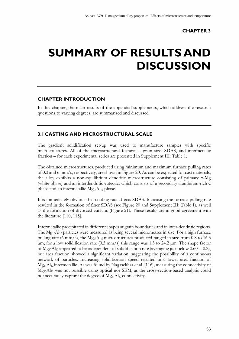
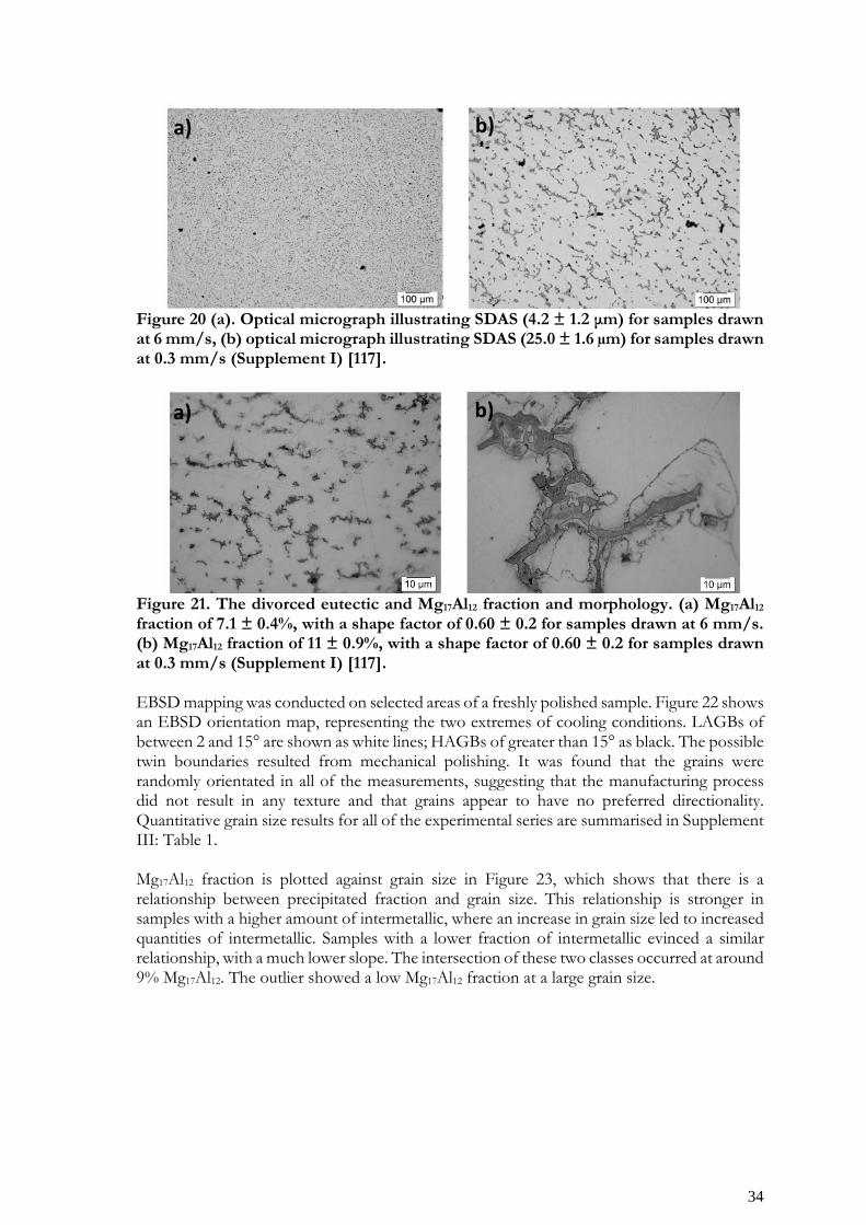
The gradient solidification set-up was used to manufacture samples with specific microstructures. All of the microstructural features – grain size, SDAS, and intermetallic fraction – for each experimental series are presented in Supplement III: Table 1. The obtained microstructures, produced using minimum and maximum furnace pulling rates of 0.3 and 6 mm/s, respectively, are shown in Figure 20. As can be expected for cast materials, the alloy exhibits a non-equilibrium dendritic microstructure consisting of primary α-Mg (white phase) and an interdendritic eutectic, which consists of a secondary aluminium-rich α phase and an intermetallic Mg17Al12 phase. It is immediately obvious that cooling rate affects SDAS. Increasing the furnace pulling rate resulted in the formation of finer SDAS (see Figure 20 and Supplement III: Table 1), as well as the formation of divorced eutectic (Figure 21). These results are in good agreement with the literature [110, 115]. Intermetallic precipitated in different shapes at grain boundaries and in inter-dendritic regions. The Mg17Al12 particles were measured as being several micrometres in size. For a high furnace pulling rate (6 mm/s), the Mg17Al12 microstructures produced ranged in size from 0.8 to 16.5 µm; for a low solidification rate (0.3 mm/s) this range was 1.3 to 24.2 µm. The shape factor of Mg17Al12 appeared to be independent of solidification rate (averaging just below 0.60 ± 0.2), but area fraction showed a significant variation, suggesting the possibility of a continuous network of particles. Increasing solidification speed resulted in a lower area fraction of Mg17Al12 intermetallic. As was found by Nagasekhar et al. [116], measuring the connectivity of Mg17Al12 was not possible using optical nor SEM, as the cross-section-based analysis could not accurately capture the degree of Mg17Al12 connectivity.
34
Figure 20 (a). Optical micrograph illustrating SDAS (4.2 ± 1.2 μm) for samples drawn at 6 mm/s, (b) optical micrograph illustrating SDAS (25.0 ± 1.6 µm) for samples drawn at 0.3 mm/s (Supplement I) [117].
Figure 21. The divorced eutectic and Mg17Al12 fraction and morphology. (a) Mg17Al12 fraction of 7.1 ± 0.4%, with a shape factor of 0.60 ± 0.2 for samples drawn at 6 mm/s. (b) Mg17Al12 fraction of 11 ± 0.9%, with a shape factor of 0.60 ± 0.2 for samples drawn at 0.3 mm/s (Supplement I) [117]. EBSD mapping was conducted on selected areas of a freshly polished sample. Figure 22 shows an EBSD orientation map, representing the two extremes of cooling conditions. LAGBs of between 2 and 15° are shown as white lines; HAGBs of greater than 15° as black. The possible twin boundaries resulted from mechanical polishing. It was found that the grains were randomly orientated in all of the measurements, suggesting that the manufacturing process did not result in any texture and that grains appear to have no preferred directionality. Quantitative grain size results for all of the experimental series are summarised in Supplement III: Table 1. Mg17Al12 fraction is plotted against grain size in Figure 23, which shows that there is a relationship between precipitated fraction and grain size. This relationship is stronger in samples with a higher amount of intermetallic, where an increase in grain size led to increased quantities of intermetallic. Samples with a lower fraction of intermetallic evinced a similar relationship, with a much lower slope. The intersection of these two classes occurred at around 9% Mg17Al12. The outlier showed a low Mg17Al12 fraction at a large grain size.

As-cast AZ91D magnesium alloy properties: Effects of microstructure and temperature
35
Figure 22. Inverse pole figure maps illustrating grain orientation. LAGBs of between 2 and 15° are shown as white lines, and HAGBs of greater than 15° are black lines. (a) for a sample pulled at 6 mm/s, with a grain size of 93 ± 4.4 µm; (b) for a sample pulled at 0.3 mm/s, with a grain size of 254 ± 3.7 µm (Supplement III) [118].
Figure 23. Mg17Al12 fraction plotted against grain size (Supplement III) [118].
5
6
7
8
9
10
11
12
13
80 130 180 230 280 330 380
Mg 1
7Al 12
frac
tion
(%)
Grain sizes (μm)
Mg17Al12 content via Grain size

36
3.2 MECHANICAL PROPERTIES AND MICROSTRUCTURAL SCALE
Figure 24 shows a typical stress-strain curve for samples of differing microstructures and strain rates at RT and 190°C. In general, there was scatter in most of the results, as is suggested by the literature on cast materials [65, 69-71, 119, 120]. Several key points can be surmised from Figure 24 and the collated data of Supplement III: Table 1.
• Unexpectedly, it was found that the sample with a finer SDAS had lower offset yield strength (Rp0.2) than the sample with a coarse microstructure. This means that there are other factors than SDAS that determine yield strength.
• The strain-rate dependence at 190°C was as expected; a lower strain rate resulted in less hardening than a higher strain rate.
• A higher fraction of Mg17Al12 resulted in a higher influence of strain rate on the offset yield strength (Rp0.2).
• Hardening was exacerbated by lower Mg17Al12 fraction and smaller SDAS. • A higher Mg17Al12 fraction appears to reduce elongation to failure.
To understand the significance of the experimental parameters with regard to the results, an ANOVA analysis was conducted using the DesignExpert™ software (see Table 6). In annotated view, the model was labelled as “significant”. The ‘F value’ column and associated probability (‘Prob. > F’) show that there was a very small probability – near 0.81% (P = 0.0081) – that the differences in the model’s parameters (A, B, D, and BD) could have occurred due to noise. Lack of fit was not significant, which is relative to ‘Pure error’; in other words, the model appeared to work correctly, based on the significant relationships between the model’s terms. It is interesting to note that two parameters – temperature (A) and Mg17Al12 fraction (D) – are significant. Strain rate (Parameter B) is marginally significant, but very close to being of significance. The interaction between strain rate and Mg17Al12 fraction (Parameter BD) is also marginally significant. The analysis did not produce any suitable fit with SDAS (Parameter C), but confirmed that temperature reduces yield strength, as expected. Figure 25 evinces an interaction between Mg17Al12 fraction and strain rate, affecting the yield strength of specimens. It is hypothesised that, at high strain rates, the effect of Mg17Al12 fraction on yield strength is more dominant. However, no significant effect was observed at lower Mg17Al12 fractions. Higher strain rates led to increased yield strength, meaning that higher fractions of Mg17Al12 result in an increased initial strength in the alloy. The average value for offset yield strength (Rp0.2) obtained at RT and 190°C is plotted against area fraction of Mg17Al12 in Figure 26(a). It was found that Mg17Al12 content strongly contributes to Rp0.2, with a higher area fraction of Mg17Al12 resulting in a higher Rp0.2 value. In addition, a linear regression analysis was carried out in order to quantify the relationship between Mg17Al12 content and Rp0.2 magnitudes, and it was revealed that there are different linear slope fits for Mg17Al12 content below 8.8% and above 11%: When Mg17Al12 content is ≥ 11%, Rp0.2 at both RT and 190°C increases with a sharper slope in comparison to lower Mg17Al12 content. Jarfors et al. [121] suggest that the intermediate connectivity of particles begins at 8%, and that by 11% particle fraction there is full connectivity between particles. Hence, it can be concluded that, by increasing Mg17Al12 fraction (above 11%), these particles begin to impinge on one another, forming a network similar to a rigid scaffold, inhibiting the continuation of slip and dislocation movement during tensile testing. Hence, failure will occur when the entire Mg17Al12 network is deformed [122]. Consequently, it can be concluded that the offset yield strength of the alloy is primarily determined by the continuous network of

As-cast AZ91D magnesium alloy properties: Effects of microstructure and temperature
37
Mg17Al12. The relationship between SDAS, grain size, and offset yield point is shown in Figure 27-(a), and can be observed that this relationship has no physical meaning.
Figure 24. Stress-strain curves for specimens deformed at a) RT and b) 190°C and a strain rate of 10-4 1/s (Supplement III) [118]. Table 6. ANOVA analysis of Rp0.2 for different factors, and their interactions with R-squared of 0.90 (Supplement I) [117].
Source Sum of squares df Mean
square F value P value Prob. > F Significance
Model 7162.69 4 1790.67 6.38 0.0081 Significant A: Temperature 1412.76 1 1412.76 5.04 0.0487 Significant
B: Strain rate 1382.93 1 1382.93 4.93 0.0507 Marginally significant
D: Mg17Al12 fraction 4122.91 1 4122.91 14.69 0.0033 Significant
BD 1190.40 1 1190.40 4.24 0.0664 Marginally significant
Residual 2805.77 10 280.58 Lack of fit 822.00 4 205.50 0.62 0.6641 Not significant Pure error 1983.77 6 330.63 Cor. total 9968.46 14
a)
b)
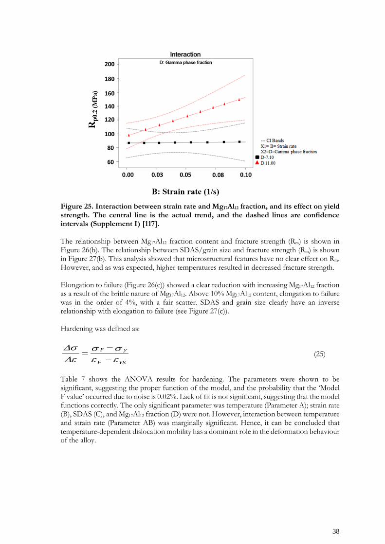
38
Figure 25. Interaction between strain rate and Mg17Al12 fraction, and its effect on yield strength. The central line is the actual trend, and the dashed lines are confidence intervals (Supplement I) [117]. The relationship between Mg17Al12 fraction content and fracture strength (Rm) is shown in Figure 26(b). The relationship between SDAS/grain size and fracture strength (Rm) is shown in Figure 27(b). This analysis showed that microstructural features have no clear effect on Rm. However, and as was expected, higher temperatures resulted in decreased fracture strength. Elongation to failure (Figure 26(c)) showed a clear reduction with increasing Mg17Al12 fraction as a result of the brittle nature of Mg17Al12. Above 10% Mg17Al12 content, elongation to failure was in the order of 4%, with a fair scatter. SDAS and grain size clearly have an inverse relationship with elongation to failure (see Figure 27(c)). Hardening was defined as:
YSF
yF
εεσσ
ε∆σ∆
−−
= (25)
Table 7 shows the ANOVA results for hardening. The parameters were shown to be significant, suggesting the proper function of the model, and the probability that the ‘Model F value’ occurred due to noise is 0.02%. Lack of fit is not significant, suggesting that the model functions correctly. The only significant parameter was temperature (Parameter A); strain rate (B), SDAS (C), and Mg17Al12 fraction (D) were not. However, interaction between temperature and strain rate (Parameter AB) was marginally significant. Hence, it can be concluded that temperature-dependent dislocation mobility has a dominant role in the deformation behaviour of the alloy.
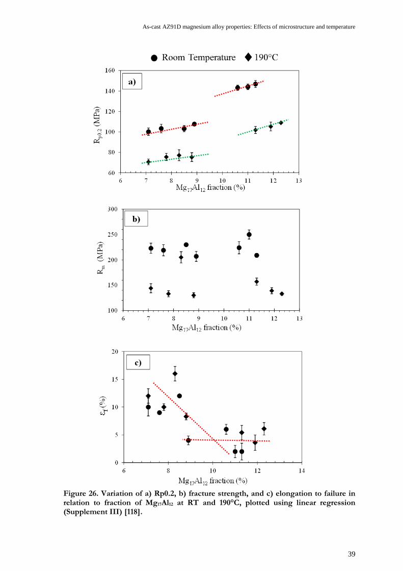
As-cast AZ91D magnesium alloy properties: Effects of microstructure and temperature
39
Figure 26. Variation of a) Rp0.2, b) fracture strength, and c) elongation to failure in relation to fraction of Mg17Al12 at RT and 190°C, plotted using linear regression (Supplement III) [118].

40
Figure 27. Variation of a) Rp0.2, b) Rm, and c) elongation to failure in relation to Mg17Al12 fraction at RT and 190°C with respect to SDAS and grain size.
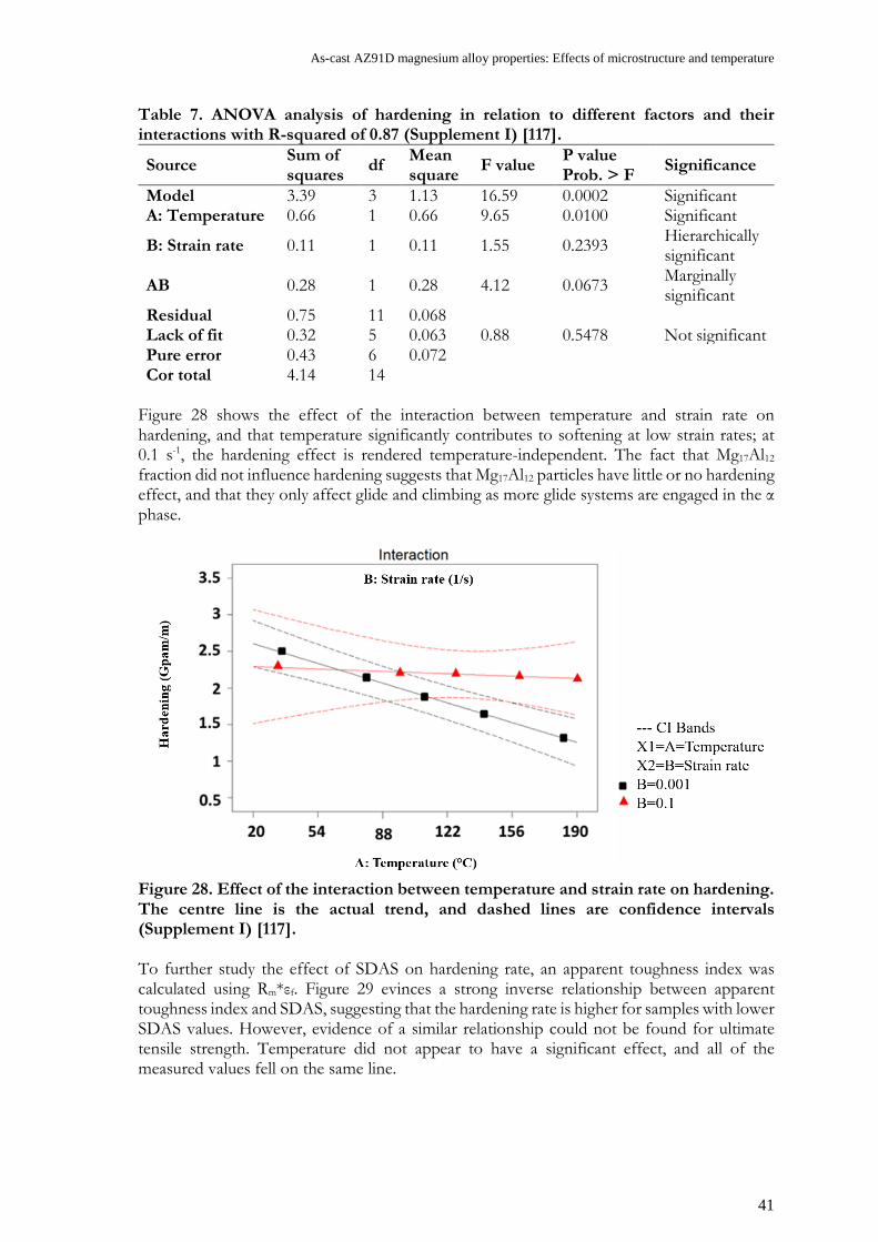
As-cast AZ91D magnesium alloy properties: Effects of microstructure and temperature
41
Table 7. ANOVA analysis of hardening in relation to different factors and their interactions with R-squared of 0.87 (Supplement I) [117].
Source Sum of squares df Mean
square F value P value Prob. > F Significance
Model 3.39 3 1.13 16.59 0.0002 Significant A: Temperature 0.66 1 0.66 9.65 0.0100 Significant
B: Strain rate 0.11 1 0.11 1.55 0.2393 Hierarchically significant
AB 0.28 1 0.28 4.12 0.0673 Marginally significant
Residual 0.75 11 0.068 Lack of fit 0.32 5 0.063 0.88 0.5478 Not significant Pure error 0.43 6 0.072 Cor total 4.14 14
Figure 28 shows the effect of the interaction between temperature and strain rate on hardening, and that temperature significantly contributes to softening at low strain rates; at 0.1 s-1, the hardening effect is rendered temperature-independent. The fact that Mg17Al12 fraction did not influence hardening suggests that Mg17Al12 particles have little or no hardening effect, and that they only affect glide and climbing as more glide systems are engaged in the α phase.
Figure 28. Effect of the interaction between temperature and strain rate on hardening. The centre line is the actual trend, and dashed lines are confidence intervals (Supplement I) [117]. To further study the effect of SDAS on hardening rate, an apparent toughness index was calculated using Rm*εf. Figure 29 evinces a strong inverse relationship between apparent toughness index and SDAS, suggesting that the hardening rate is higher for samples with lower SDAS values. However, evidence of a similar relationship could not be found for ultimate tensile strength. Temperature did not appear to have a significant effect, and all of the measured values fell on the same line.

42
Figure 29. Apparent toughness as a function of SDAS at both RT and 190°C (Supplement III) [118].
3.3 THERMAL EXPANSION BEHAVIOUR AND MICROSTRUCTURAL SCALE
Thermal expansion generally leads to stress generation and, eventually, creep behaviour. In order to better understand the properties of the alloy at high temperatures, it is important to understand the correlation between the microstructure and thermal expansion behaviour of the alloy. Figure 30 shows the relative elongation of AZ91D with two different microstructures as a function of temperature between 323 and 423 K (50-150°C) over five cycles. It was found that the cast alloy with a lower fraction of intermetallic expanded more than the alloy containing a higher intermetallic fraction. CTE as a function of temperature is calculated as follows:
)ll(
T∆α
∂∂
= (26)
where l is the actual length of the specimen at T. The mean linear thermal expansion coefficient can be derived as follows:
)Tl(
l1
0 ∆∆α =
(27) where 0l is the initial specimen length, and l∆ is the change in length over a temperature interval T∆ .
200
700
1200
1700
2200
2700
3200
3700
3 8 13 18 23
K (M
Pa m
m-1
10-2)
SDAS (μm)
Room Temperature 190°C
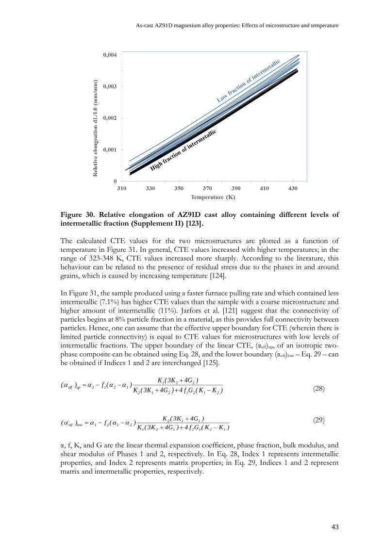
As-cast AZ91D magnesium alloy properties: Effects of microstructure and temperature
43
Figure 30. Relative elongation of AZ91D cast alloy containing different levels of intermetallic fraction (Supplement II) [123]. The calculated CTE values for the two microstructures are plotted as a function of temperature in Figure 31. In general, CTE values increased with higher temperatures; in the range of 323-348 K, CTE values increased more sharply. According to the literature, this behaviour can be related to the presence of residual stress due to the phases in and around grains, which is caused by increasing temperature [124]. In Figure 31, the sample produced using a faster furnace pulling rate and which contained less intermetallic (7.1%) has higher CTE values than the sample with a coarse microstructure and higher amount of intermetallic (11%). Jarfors et al. [121] suggest that the connectivity of particles begins at 8% particle fraction in a material, as this provides full connectivity between particles. Hence, one can assume that the effective upper boundary for CTE (wherein there is limited particle connectivity) is equal to CTE values for microstructures with low levels of intermetallic fractions. The upper boundary of the linear CTE, (αeff)up, of an isotropic two-phase composite can be obtained using Eq. 28, and the lower boundary (αeff)low – Eq. 29 – can be obtained if Indices 1 and 2 are interchanged [125].
)KK(Gf4)G4K3(K)G4K3(K)(f)(
2121212
2211212upeff −++
+−−= αααα (28)
)KK(Gf4)G4K3(K)G4K3(K)(f)(
1212121
1122121loweff −++
+−−= αααα (29)
α, f, K, and G are the linear thermal expansion coefficient, phase fraction, bulk modulus, and shear modulus of Phases 1 and 2, respectively. In Eq. 28, Index 1 represents intermetallic properties, and Index 2 represents matrix properties; in Eq. 29, Indices 1 and 2 represent matrix and intermetallic properties, respectively.

44
Figure 31. CTE for AZ91D alloys, cast with 6 mm/s and 0.3 mm/s drawing speeds, plotted against temperature. The error bars are 95% confidence intervals. The line shows the upper boundary fit for calibration of CTE for the AZ91D samples, showing no intermetallic connectivity The upper boundary fit obtained from the actual CTE value for the 6 mm/s drawing-rate sample with low fraction of intermetallic (Supplement II) [123]. It is assumed that (αeff) in Eq. 28 is equal to the obtained CTE value of samples with lower quantities of intermetallic. Accordingly, the temperature dependencies of K1 and G1, corresponding to the bulk and shear modulus of the intermetallic, were obtained from the work of Zhang et al. (2010) [126]. With α1, K1, G1, and f1 corresponding to CTE and bulk, shear, and area fraction of intermetallic, respectively, the α2, K2, and G2 values corresponding to those of the matrix were obtainable [126]. Accordingly, the actual CTE value of the upper boundary fit of the matrix as a function of temperature was derived using a model with a second-order equation. Figure 32 consists of graphs showing changes in CTE in relation to the matrix and intermetallic fraction. The temperature dependency of the bulk modulus and shear modulus of the matrix were derived in the same way, and compared with the available results for intermetallic modulus [126]. The elastic modulus of the matrix and intermetallic fractions are presented in Figure 33. Based on the obtained results for the lower boundary of linear CTE, (αeff) low was calculated. In Eq. 29, α1, K1, G1, and f1 are the CTE, bulk modulus, shear modulus, and phase fraction of matrix respectively, and α2, K2, and G2 correspond to CTE and bulk modulus, shear modulus of intermetallic respectively. The value of the CTE lower boundary was then obtained, and is shown along with the upper CTE boundary in Figure 34. The lower boundary fits relatively well with the experimental CTE values obtained for the sample with a coarse microstructure.
2,5
2,6
2,7
2,8
2,9
3
3,1
318 338 358 378 398 418
Aver
age
linea
r CTE
α (1
/K)
Temprature (°K)
CTE upper boundary
CTE experimental results for 0.3 mm/s drawing speed
CTE experimental results for 6 mm/s drawing speed
*𝟏𝟎𝟎−𝟓

As-cast AZ91D magnesium alloy properties: Effects of microstructure and temperature
45
Figure 32. Temperature dependency of the CTE of the matrix and intermetallic phases. Matrix CTE values were obtained using the CTE upper boundary fit; intermetallic values were obtained from the literature [126] (Supplement II) [123].
Figure 33. Temperature dependency of the bulk and shear modulus of the matrix phase of the AZ91D and intermetallic (Mg17Al12), plotted against temperature (Supplement II) [123]. The obtained results validated the first assumption; that the upper CTE boundary fits with the CTE values of a microstructure containing relatively little intermetallic. This means that the idea of existing a relationship between the connectivity of the particles and CTE values is valid. CTE values of AZ91D is a result of the interaction of the CTE values of the matrix and intermetallic phases. The CTE value of intermetallic is lower than that of the matrix, leading
2,4
2,5
2,6
2,7
2,8
2,9
3
3,1
323 333 343 353 363 373 383 393 403 413
Aver
age
linea
r C
TE α
(1/K
)
*𝟏𝟎𝟎−𝟓*𝟏𝟎𝟎−𝟓
Temperature (K)
20
25
30
35
40
45
50
318 338 358 378 398 418
Ela
stic
Mod
ulus
(G
Pa)
Temperature (K)
Matrix Shear Modulus

46
to less expansion as a result of increasing temperature. Increasing the fraction of intermetallic causes Mg17Al12 particles to begin to impinge on one another and form a network. Consequently, an alloy with a higher intermetallic fraction expands less than one with a lower fraction of Mg17Al12. This result supports the correlation of the offset yield point of the alloy with the presence of a network of intermetallic, as is discussed in Section 3.2.
Figure 34. The upper (0.3 mm/s drawing rate) and lower (0.3 mm/s drawing rate) CTE boundaries for AZ91D; the triangular points represent the experimental results for a sample with a high intermetallic fraction, and have a 95% confidence interval (Supplement II) [123].
3.4 MODELLING THE PLASTIC FLOW OF AZ91D
The model proposed in this study has the ability to correlate the flow stress and the microstructure of the material, as it is described in Section 1.7. It was originally developed for wrought alloys, but was here adopted for use with the AZ91D alloy. The initial microstructural inputs were SDAS and the obtained temperature-dependent parameters across a wide variety of microstructures. The model considers the alloy to be a monophase matrix containing reinforcing particles. In order to further develop the model, a set of parameters was derived from the experimental flow stress-strain curves, and calibration data was obtained from the literature.
3.4.1 Calibration of the model
The calibration parameters obtained from the literature are collated in Supplement V: Table A1. Poisson’s ratio was assumed to be a constant; υ = 0.35 [111]. The value of Young’s modulus (E) as a function of temperature was obtained using Eq. 30 [127]. Shear modulus was obtained through the calculation of the Young’s modulus value [111].
50.516 0.0208T- E += (30)
2,5
2,6
2,7
2,8
2,9
3
3,1
318 338 358 378 398 418
Aver
age
linea
r C
TE α
(1/K
)
Temperature (K)
*𝟏𝟎𝟎−𝟓

As-cast AZ91D magnesium alloy properties: Effects of microstructure and temperature
47
The Taylor factor was selected due to the available slipping systems. For HCP metals in which basal slip is activated at low stress, the Taylor factor has been suggested to be 6.5 [128], and Caceres et al. [129] estimated the Taylor factor for random magnesium polycrystals to be 4.5. For polycrystalline magnesium with a specific texture that inhibits basal and prismatic slip while favouring pyramidal polyslip, the Taylor factor is between 2.1 and 2.5. However, for the AZ91D alloy, Yuan et al. [130] obtained values of 2.3 and 2.1 for processing direction (PD) and transverse direction (TD), respectively, using EBSD. Other reports [122, 131] assumed a Taylor factor of 3 when basal slip was defined as the slipping system. In this work, the Taylor factor was considered to be 3, which is the intermediate value of the literature [122, 129-131]. Moreover, it is stated that in a temperature range of RT to 190°C, the Taylor factor can be assumed to be a constant value as the same slip systems are active during deformation [32]. The increase in entropy corresponding to the formation of vacancies, ΔSvf (relating to recovery by climb [93]), is in the order of 0.5-2k (k = Boltzmann's constant) for temperatures above the Debye temperature. In this study, it was assumed that ΔSvf = k. [98]. The self-diffusion activation energy of a magnesium lattice is 135 kJ·mol-1 [86], and that of aluminium in magnesium is 143 kJ·mol−1 [132]. The average Q was assumed to be 138 kJ·mol−1 [68] – a value that is reasonably close to the activation energy for self-diffusion in magnesium. The activation energy for vacancy migration, Qvm , has been reported to be in the range of 38-76 kJ·mol-1 [133]. The activation energy for vacancy formation, Qvf , has been reported to be in the range of 55-85 kJ·mol−1 [133, 134]. This study adapted data from Frost et al. [68]: Qvf = 81 kJ·mol−1
and Qvm = 54 kJ·mol−1. The value for initial vacancy diffusivity (Dvm) corresponds to pure magnesium [86].
3.4.2 Model and experiments
The model was initially applied to five test conditions, described in Supplement V: Table A2 and identified by (*). The selected conditions represent different microstructures, strain rates, and temperatures. The results of the testing were smoothed to remove fluctuations due to machine error. The experiments and predictions of the model are compared in Figure 35, with the dotted lines denoting experiments and solid lines denoting predictions. The overall model showed a reliable fit with the experimental data, although at 190°C the test conditions deviated slightly from the model.
3.4.3 Optimised model parameters
The optimised parameters are presented in Table 8. As is discussed above, a correlation with SDAS was achieved using Eq. 13, wherein SDAS influences the initial mean free path, before the subcell structure hinders dislocation motion. Hence, the range of parameters shown in Table 8 is applicable to a range of AZ91D microstructures. The parameter ΔF is characterised as the strength of a single obstacle; ΔF = Δf0Gb3 [135]. Obstacles were classified based on their strength, as suggested by Frost et al. [68]. An optimised ∆f0 value of 0.29 was obtained at RT, increasing to 0.56 at 190°C. In this temperature range the obstacles are precipitates that can be characterised as weak, suggesting that the intermetallic has a limited effect on hardening and deformation occurs primarily within the matrix [68].
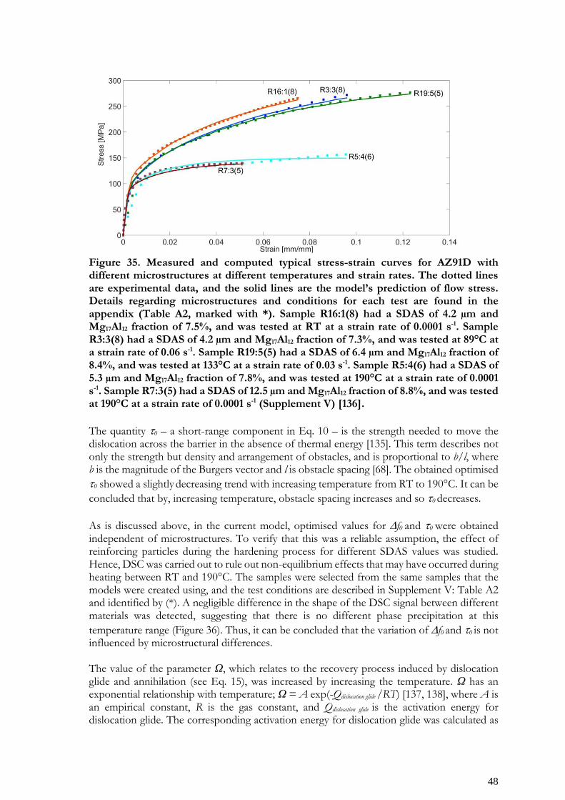
48
Figure 35. Measured and computed typical stress-strain curves for AZ91D with different microstructures at different temperatures and strain rates. The dotted lines are experimental data, and the solid lines are the model’s prediction of flow stress. Details regarding microstructures and conditions for each test are found in the appendix (Table A2, marked with *). Sample R16:1(8) had a SDAS of 4.2 µm and Mg17Al12 fraction of 7.5%, and was tested at RT at a strain rate of 0.0001 s-1. Sample R3:3(8) had a SDAS of 4.2 µm and Mg17Al12 fraction of 7.3%, and was tested at 89°C at a strain rate of 0.06 s-1. Sample R19:5(5) had a SDAS of 6.4 µm and Mg17Al12 fraction of 8.4%, and was tested at 133°C at a strain rate of 0.03 s-1. Sample R5:4(6) had a SDAS of 5.3 µm and Mg17Al12 fraction of 7.8%, and was tested at 190°C at a strain rate of 0.0001 s-1. Sample R7:3(5) had a SDAS of 12.5 µm and Mg17Al12 fraction of 8.8%, and was tested at 190°C at a strain rate of 0.0001 s-1 (Supplement V) [136]. The quantity τ0 – a short-range component in Eq. 10 – is the strength needed to move the dislocation across the barrier in the absence of thermal energy [135]. This term describes not only the strength but density and arrangement of obstacles, and is proportional to b/l, where b is the magnitude of the Burgers vector and l is obstacle spacing [68]. The obtained optimised τ0 showed a slightly decreasing trend with increasing temperature from RT to 190°C. It can be concluded that by, increasing temperature, obstacle spacing increases and so τ0 decreases. As is discussed above, in the current model, optimised values for ∆f0 and τ0 were obtained independent of microstructures. To verify that this was a reliable assumption, the effect of reinforcing particles during the hardening process for different SDAS values was studied. Hence, DSC was carried out to rule out non-equilibrium effects that may have occurred during heating between RT and 190°C. The samples were selected from the same samples that the models were created using, and the test conditions are described in Supplement V: Table A2 and identified by (*). A negligible difference in the shape of the DSC signal between different materials was detected, suggesting that there is no different phase precipitation at this temperature range (Figure 36). Thus, it can be concluded that the variation of ∆f0 and τ0 is not influenced by microstructural differences. The value of the parameter Ω, which relates to the recovery process induced by dislocation glide and annihilation (see Eq. 15), was increased by increasing the temperature. Ω has an exponential relationship with temperature; Ω = A exp(-Qdislocation glide /RT) [137, 138], where A is an empirical constant, R is the gas constant, and Qdislocation glide is the activation energy for dislocation glide. The corresponding activation energy for dislocation glide was calculated as

As-cast AZ91D magnesium alloy properties: Effects of microstructure and temperature
49
being in the order of 5 kJ·mol-1. It was found that the activation energy for dislocation glide can be expected to be lower than the activation energy for forest dislocation cutting, which is in the order of Gb3/4π [137]. This value at RT is equal to 26.48 kJ·mol-1. KC was assumed to be a temperature-dependent parameter that is related to the dislocation subcell diameter (see Eq. 14). Considering the mean free path described by Eq. 13, it can be concluded that a higher KC value results in a larger subcell size and mean free path, and thus less hardening effects. However, both subcell size and therefore mean free path are also strongly dependent on the rate of recovery of dislocation. As the rate of recovery increases with temperature, this also leads to an increase in subcell size.
Figure 36. DSC curves for the five AZ91D alloy samples with varying SDAS values and Mg17Al12 fractions, showing that no phase transformation or other significant non-equilibrium events occurred during heating (Supplement V) [136].

50
Table 8. Optimised temperature-dependent parameters for AZ91D (Supplement V) [136]. T(°C) 20 89 133 190 τ0 0.03817 0.0365 0.03657 0.026 ∆f0 0.2985 0.2702 0.33746 0.5612 Kc 18.66 20.609 20.9291 24.368 Ω 27.83 23.7823 24.3643 74.445 α Constant = 0.7 cγ Constant = 0.0029 p Constant = 0.55 q Constant = 1.68
3.4.4 Model validation using microstructural characterisation
Comparison of predicted and measured dislocation densities
The model’s validity was confirmed by comparing the predicted dislocation density with the measured values for the tensile samples. The computed dislocation density values are identical to three of the fitted curves (see Figure 35), and are shown in Figure 37. Based on the EBSD data, KAM maps were created to measure the local misorientations. KAM quantifies the average misorientation around a measurement point in relation to a defined set of neighbouring points. Typical KAM maps are shown in Figure 37. Accordingly, the geometrically necessary dislocation (GND) densities were calculated as follows [139]:
bLGNDφρ = (31)
where φ is the rotation angle of the crystal lattice, obtained using KAM data for the unit length of L , which is here equal to twice the EBSD step size (2 × 0.8 μm, as the KAM analysis was based on the second-nearest set of neighbouring pixels), and b is the magnitude of the Burgers vector. The GND densities were calculated based on the KAM data, which defines the rotation angle, φ , at specific points on the EBSD map. The second-neighbour rank, corresponding to a distance of 1.6 µm, is most optimal for obtaining scatter-free information [139]. Typical GND density maps of deformed samples are shown in Figure 37. The average
GNDρ values were calculated using the EBSD data of five different areas of each sample. The average GNDρ values of the specimens were comparable to the final dislocation density values predicted by the model (Figure 37). Here, it should be mentioned the statistically stored dislocation (SSD) densities and GND densities are contributing to the flow stress of the material [139]. However, it is also recognized that only the GND density is responsible for the long-range contribution of flow stress [140] and so it is comparable with final dislocation density value predicted by the model. The predicted values were in good agreement with the experimental results, and thereby validate the model, (Figure 37). It should be noted that the calculated GND densities (Figure 37) were in good agreement with the available data regarding crystallographic HCP materials [141, 142] and magnesium [143]. The model shows that dislocation density increases with increasing strain rate (see Figure 38). Dislocation density is determined by the balance between strain hardening and dynamic recovery [84]. As strain rate increases, a higher value of dislocation density at a steady state is formed, leading to a higher saturation stress level.

As-cast AZ91D magnesium alloy properties: Effects of microstructure and temperature
51
Furthermore, the model predicts that immobile dislocation density increases with decreasing deformation temperature (see Figure 39). The experimentally measured GND densities for the deformed samples, plotted as stress-strain curves in Figure 39, show good agreement with the model’s predictions. The specimens deformed at RT had higher dislocation densities than those deformed at 190°C. Hence, there is a high density of randomly-tangled dislocations at RT. It is well established that a high density of straight-edge dislocations, and distribution of these dislocations, results in the formation of subcells or dislocation cells [144]. The formation of a subcell is accompanied by high stacking-fault energy, aiding cross-slip and thereby cell formation [145]. Comparison of predicted and measured subcell sizes
Subcell size can be predicted for different test conditions using Eq. 14, the optimised KC values of which are presented in Table 8 for the relevant temperatures. An attempt was made to measure subcell size using LAGB maps. In a cast material, the presence of an additional length scale – i.e. SDAS – inside the grains affect the formation of the subcell structure. Hence, and unlike with wrought materials, estimating the subcell sizes of cast alloys using LAGB maps is difficult and likely less accurate. A typical LAGB map obtained through EBSD analysis is shown in Figure 40. The subcell sizes were measured for two deformed samples with fine (SDAS = 4.7 µm; grain size = 93.54 µm) and coarse (SDAS = 26.5 µm; grain size = 278.64 µm) microstructures at RT and a strain rate of 10-4 s-1. The changes in subcell size at specific strain values were studied. Figure 41 shows the histograms and bimodal fits of subcell size measured using the LAGB maps of deformed samples. As strain increases, the partitioning between the two distributions shifts towards the smaller subcell scale. For lower SDAS values (Figure 41(a-c)), this smaller subcell scale moved towards the value of the SDAS. For higher SDAS values (Figure 41(d-f)), the subcell scales were smaller than the SDAS values, and the structure was not influenced nor limited by SDAS in the same way. Thus, this area requires further investigation.

52
Figure 37. Typical KAM map, comparing the GND density maps and experimental dislocation density to the model’s predictions for samples deformed under tensile testing conditions. The EBSD data was collected from the second-nearest set of neighbouring pixels. The black regions in the KAM maps, corresponding to the white regions in the GND maps, are non-indexed areas (Supplement V) [136].

As-cast AZ91D magnesium alloy properties: Effects of microstructure and temperature
53
Figure 38. Dependency of computed dislocation densities on strain rate.
Figure 39. Evolution of dislocation density for different microstructures and temperatures at a constant strain rate (0.0001 1/s). The markers delineate the experimental dislocation density of the deformed samples, and the lines are the model’s prediction of dislocation density from the initial state to the deformation state (Supplement V) [136].

54
Figure 40. Typical LAGB map for a sample deformed during tensile testing at 89°C and a strain rate of 0.0001 s-1.

As-cast AZ91D magnesium alloy properties: Effects of microstructure and temperature
55
Figure 41. Histograms and bimodal fits of subcell sizes measured on LAGB maps of deformed AZ91D samples. Each graph corresponds to a sample; Samples a, b, and c had an average SDAS of 4.7 µm and average grain size of 93.54 µm. Samples d, e, and f had an average SDAS of 26.5 µm and average grain size of 278.64 µm (Supplement IV) [146].
3.5 EFFECT OF HPDC ON DISTORTION AND RESIDUAL STRESS
The influence of HPDC parameters – first-phase injection speed (A), the temperature difference between the two die halves (B), cooling time (C), and intensification pressure (D) – on distortion and the residual stress response of magnesium components were studied. This study was performed using samples following HPDC, and on samples following post-treatment processes such as shot peening and paint baking. The experimental design of the work is discussed in Section 2.3.3.

56
3.5.1 Analysis of distortion measurements
The experimental conditions and results of the distortion measurements after casting and post-treatment are presented in Supplement VI: Table 3, and Supplement VII: Table 3 respectively. An attempt was made to describe the distortion responses in relation to the HPDC process parameters using ANOVA. However, statistical significance model was found for cast components only at Point D5 (Figure 17), and no statistical significance model was found for components treated by shot peening and painting at any of the points. An ANOVA analysis of the distortion responses of cast components at Point D5 was conducted, the results of which are shown in Table 9. Table 9. ANOVA response surface reduced quadratic model for distortion response at point D5 [105].
ANOVA analysis showed that Parameters B (the temperature of the fixed half of the die), and D (intensification pressure) were statistically significant. Moreover, B2 and D2 were also statistically significant, as was the interaction between B and D, hierarchically. It should be noted that a model wherein Parameters A and C were statistically significant was created, but not used due to the lack of physical significance in relation to distortion. Further analysis revealed that intensification pressure has the most significant influence on distortion responses at Point D5, and that the effect of temperature on the fixed half of the die (Parameter B) is relatively weak. Figure 42 shows that increasing the intensification pressure results in less distortion, and the response of the surface to interaction between Parameters B and D shows that, at low intensification pressures, the temperature difference between dies has a stronger influence.
Source Sum of squares df Mean
square F value P value Prob. > F Significance
Model 34.30 5 6.86 166.00 < 0.0001 Significant B: Temperature of fixed half of the die 1.04 1 1.04 25.21 0.0002 Significant
D: Intensification pressure 18.43 1 18.43 446.08 < 0.0001 Significant
BD 0.034 1 0.034 0.82 0.3792
Kept for model; hierarchically significant
B2 3.26 1 3.26 79.01 < 0.0001 Significant D2 4.59 1 4.59 110.98 < 0.0001 Significant Residual 0.62 15 0.041
Lack of fit 0.59 12 0.049 4.61 0.1174 Not significant Pure error 0.032 3 0.011
Cor total 34.92 20
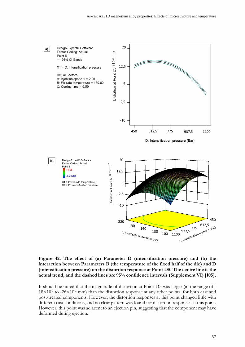
As-cast AZ91D magnesium alloy properties: Effects of microstructure and temperature
57
Figure 42. The effect of (a) Parameter D (intensification pressure) and (b) the interaction between Parameters B (the temperature of the fixed half of the die) and D (intensification pressure) on the distortion response at Point D5. The centre line is the actual trend, and the dashed lines are 95% confidence intervals (Supplement VI) [105].
It should be noted that the magnitude of distortion at Point D3 was larger (in the range of -18×10-2 to -26×10-2 mm) than the distortion response at any other points, for both cast and post-treated components. However, the distortion responses at this point changed little with different cast conditions, and no clear pattern was found for distortion responses at this point. However, this point was adjacent to an ejection pin, suggesting that the component may have deformed during ejection.

58
3.5.2 Analysis of residual stress measurements
The residual stress responses of cast and post-treated components are collated in Supplement VI: Table 4 and Supplement VII: Table 4, respectively. Typical SVMS profiles for all of the conditions were evaluated at Point R1 and are plotted in Figure 43.
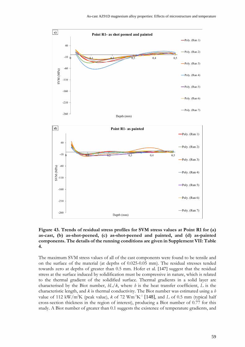
As-cast AZ91D magnesium alloy properties: Effects of microstructure and temperature
59
Figure 43. Trends of residual stress profiles for SVM stress values at Point R1 for (a) as-cast, (b) as-shot-peened, (c) as-shot-peened and painted, and (d) as-painted components. The details of the running conditions are given in Supplement VII: Table 4. The maximum SVM stress values of all of the cast components were found to be tensile and on the surface of the material (at depths of 0.025-0.05 mm). The residual stresses tended towards zero at depths of greater than 0.5 mm. Hofer et al. [147] suggest that the residual stress at the surface induced by solidification must be compressive in nature, which is related to the thermal gradient of the solidified surface. Thermal gradients in a solid layer are characterised by the Biot number, hL/k, where h is the heat transfer coefficient, L is the characteristic length, and k is thermal conductivity. The Biot number was estimated using a h value of 112 kW/m2K (peak value), k of 72 Wm-1K-1 [148], and L of 0.5 mm (typical half cross-section thickness in the region of interest), producing a Biot number of 0.77 for this study. A Biot number of greater than 0.1 suggests the existence of temperature gradients, and

60
hence compressive residual stress in the surface. However, in this study only tensile residual tensile stresses were found at the surfaces of cast components. To understand the significant influence of HPDC parameters on the residual stress responses of cast components at Point R1, an ANOVA analysis was conducted, the results of which are presented in Table 10. Table 10. ANOVA response surface reduced quadratic model for residual stress response at Point R1. (Supplement VI) [105].
The ANOVA results revealed that Parameters B and D were statistically significant. The interaction between these two parameters and Parameter D2 was hierarchically significant. However, further results revealed that intensification pressure had a much greater influence than the temperature of the fixed half of the die on the residual stress responses of the surface. Figure 44(a) shows this influence, wherein an increased intensification pressure strongly increased residual stress at Point R1. The interaction between Parameters B and D is shown in Figure 44(b). The effect of the temperature of the fixed half of the die was less pronounced at low intensification pressures than high ones, at which an increase in the temperature of the fixed half of the die reduced residual stress. This behaviour suggests that relaxation occurs due to contact with the die. A similar in-die relaxation was observed in the literature [149] as a change in the early-stage hardening in the stress-strain behaviour of thin-walled AZ91D test samples.
Source Sum of squares
df Mean square F value P value
Prob. > F Significance
Model 3836.97 4 959.24 203.89 < 0.0001 Significant B: Temperature of fixed half of the die 82.06 1 82.06 17.44 0.0006 Significant
D: Intensification pressure 2807.46 1 2807.46 596.75 < 0.0001 Significant
BD 33.93 1 33.93 7.21 0.0151 Significant D2 207.26 1 207.26 44.06 < 0.0001 Significant Residual 84.68 18 4.70 Lack of fit 3.51 3 1.17 0.22 0.8837 Not significant Pure error 81.17 15 5.41 Cor total 3921.65 22

As-cast AZ91D magnesium alloy properties: Effects of microstructure and temperature
61
Figure 44. The effect of (a) Parameter D (intensification pressure) on residual stress at Point R1 and (b) the interaction between Parameters B (temperature of the fixed side of the die) and D (intensification pressure) on residual stress at Point R1. The dashed lines are 95% confidence intervals [105]. It should be noted that the strong effect of intensification pressure was also detected for residual stress responses at Points R2 and R3 (see Supplement VI). Furthermore, the residual stresses at the surfaces (depths of 0.025-0.05 mm) of i) as-cast, ii) as-shot-peened, iii) as-shot-peened and painted, and iv) as-painted components were compared. The following conclusions were drawn:

62
• Residual stresses at the surfaces of all of the components were tensile, except for those of as-shot-peened components. Shot peening induced compressive residual stress at the surface.
• Comparing as-cast and post-treated components in relation to surface residual stress led to an interesting realisation: Cast components with relatively high SVM stress values at the surface still have higher SVM stress values at the surface even after post-treatment processes.
• As the residual stress of as-cast components showed that intensification pressure has a strong influence on SVMS values at the surface, it is suggested that this influence may remain after post-treatment processes.
An ANOVA analysis was used to understand the influence of HPDC process parameters on the surface residual stress responses of components after shot peening. Table 11 presents the ANOVA results at Point R1. From these, it can be understood that Parameter D (intensification pressure) is statistically significant, as is the interaction between Parameters C (cooling time) and D (intensification pressure). Hence, Parameter C was a hierarchically important parameter. Table 11. ANOVA response of surface residual stress responses at Point R1 after shot peening with R-squared of 0.97.
Source Sum of squares df Mean
square F value
P value Prob. > F
Significance
Model 50657.39 6 8442.9 139 < 0.0001 Significant C: Cooling time 166.64 1 166.64 2.74 0.116
D: Intensification pressure 11157.15 1 11157.1
5 183.69 < 0.0001
CD 1668.53 1 1668.53 27.47 < 0.0001
Residual 1032.57 17 60.74
Lack of fit 184.33 1 184.33 3.48 0.0807 Not significant Pure error 848.24 16 53.01
Cor total 51689.96 23 Additional analysis revealed that only intensification pressure has a strong effect on surface residual stress at Point R1. A decreased intensification pressure strongly increased compressive residual stress (see Figure 45(a)). The interaction of Parameters C and D showed that a longer cooling time decreases intensification pressure, resulting in more compressive residual stress at the surface at Point R1 (see Figure 45(b)).

As-cast AZ91D magnesium alloy properties: Effects of microstructure and temperature
63
Figure 45. The effect of (a) Parameter D (intensification pressure) and (b) the interaction between Parameters C (cooling time) and D (intensification pressure) on surface residual stress at Point R1 for as-shot-peened components. The centre line is the actual trend, and the dashed lines are 95% confidence intervals. No statistically reliable model could be created to model the influence of the process parameters on the residual stress responses of as-shot-peened and painted components, nor as-painted components. Figure 46 shows the variation of surface residual stress plotted against intensification pressure for i) as-shot-peened and painted and ii) as-painted components, and shows that an increase in intensification pressure led to an increase in residual stress at the surface. However, the role of other process parameters was not clear.

64
Figure 46. Variation of 𝝈𝝈𝒔𝒔𝒓𝒓𝒔𝒔responses with intensification pressure at Point R1 for i) as-shot-peened and painted and ii) as-painted components. The dashed lines are linear trendlines. In summary, it can be concluded that intensification pressure has a strong effect on the surface residual stress of both cast and post-treated components at Point R1. Similar results were achieved for other locations on the crank case, as it is described in Supplements VI and VII.
0
5
10
15
20
25
30
35
40
45
50
300 500 700 900 1100
Intensification pressure (Bar)
As-shot-peened and painted – Point R1
As-painted – Point R1
Linear (As-shot-peened and painted –Point R1)
Linear (As-painted – Point R1)
σ srs (
MPa
)
As-cast AZ91D magnesium alloy properties: Effects of microstructure and temperature
65
CHAPTER 4
CONCLUDING REMARKS
CHAPTER INTRODUCTION
This chapter summarises the conclusions that have been drawn based on the results of this study.
This work aimed to provide a better understanding of the properties and performance of the AZ91D alloy in relation to microstructure and processing parameters. Hence, an attempt was made to correlate the microstructure and mechanical properties of AZ91D and study its mechanical performance during processes. The main conclusions drawn are as follows: Correlation between manufacturing techniques and microstructure Different solidification speeds (slow to fast cooling) were tested to generate a variety of microstructures corresponding to different casting states by using Bridgman solidification technique. The samples had isotropic microstructures, with no texture. It was observed that both grain size and SDAS decrease with increasing solidification speed. The area fraction of Mg17Al12 increased with decreasing solidification speed. The shape factor of Mg17Al12 was independent of the solidification rate (0.60 ± 0.2). It was found that there is a relationship between intermetallic fraction and grain size; by increasing the grain size, the intermetallic fraction increased. The samples containing a higher fraction indicated a stronger relationship between these two parameters.
Correlation between microstructure and mechanical properties The Mg17Al12 content of the alloy strongly contributed to its offset yield point (Rp0.2), and Rp0.2 appears to be independent of SDAS values. Two different groups of behaviours could clearly be observed. Both the magnitude of Rp0.2 and its dependence on the fraction of Mg17Al12 was between 9 and 11%. A higher fraction of Mg17Al12 (≥ 11%) resulted in the formation of a rigid network, which increased the offset yield point. Analysing the results of elongation to failure tests showed a clear reduction with an increasing Mg17Al12 fraction. Above a Mg17Al12 fraction of 10%, elongation to failure was in the order of 4%, with a fair scatter. Ultimate tensile strength largely depended on temperature, and no statistically significant dependence on grain size, SDAS, nor Mg17Al12 fraction could be established. In addition, hardening rates were higher for smaller SDAS values, and analysis of apparent toughness showed a strong inverse relationship with SDAS.
Correlation between microstructure and thermal expansions The connectivity of the intermetallic phase contributed strongly to the thermal expansion of the alloy. The lower CTE boundary suggests the possibility of Mg17Al12 network formation for a high intermetallic fraction (≥ 11%). The CTE curve on the upper boundary corresponded to a low fraction of intermetallic (< 8%), meaning that there is no intermetallic connectivity. The lower CTE of intermetallic caused a reduced sensitivity to increasing

66
temperature. Hence, the existence of a continuous network of intermetallic through increases in and impingement of the Mg17Al12 particles was supported. Modelling of flow-stress behaviour and model validity A dislocation density model was optimised in order to describe the flow stress of cast AZ91D with a limited number of adjustable parameters, all of which have clear physical relevance. The model presented factors relating to the effects of microstructural scale on the deformation behaviour of the alloy. The model’s validity was reasonably well confirmed by comparing the predicted dislocation density and GND dislocation density obtained through EBSD data. The unique aspect of this modelling approach is that the predicted tensile curves were obtained with relatively high accuracy, and the obtained optimised parameters are applicable to all microstructural range. This will facilitate the usage of the model in future simulation efforts in which predicting the mechanical properties that result from certain manufacturing techniques is desirable. Correlation of HPDC process parameters to distortion and residual stress The application of intensification pressure significantly reduced the as-cast component’s distortion at Point D5. A decrease in the temperature difference between the two die halves reduced the distortion of as-cast components. A component cast using specific HPDC parameters showed a higher magnitude of residual surface stress even after any post-treatment processes compare to others. Furthermore, shot peening induced compressive stress at the surface of the component. The hypothesis for this phenomenon is that increasing intensification pressure significantly increases the residual tensile stress near the surface of as-cast and post-treated components. For as-cast components, the second most important parameter was the temperature of the fixed half of the die. Increasing the temperature of the non-fixed side of the die decreased the residual stress near the surface of the component.

As-cast AZ91D magnesium alloy properties: Effects of microstructure and temperature
67
CHAPTER 5
FUTURE WORK
CHAPTER INTRODUCTION
Based on the presented results and findings, several future projects to achieve the sustainable design of AZ91D magnesium alloys are suggested.
While the work presented in this thesis has resulted in new knowledge regarding the mechanical properties/performance of the AZ91D alloy, it is also raises several new issues to be addressed by future research. Compression flow behaviour and twinning This thesis provides a comprehensive insight on the role of microstructural constitute on the tensile properties of AZ91D alloy at different temperatures. A model to describe the flow stress was introduced as well. However, understanding the behaviour of the material under compression conditions would be beneficial, and twinning – as one of the deformation mechanisms that occurs under such conditions – should be considered to be a research area of interest. Accordingly, physical modelling to predict compression flow curves should be conducted. Creep behaviour In this thesis, deformation mechanisms at high stress and moderate temperature were studied. Moreover, the relation of the deformation mechanisms with microstructural features was studied. However, significant research is required to correlate the microstructure of the AZ91D alloy with its creep properties. The controlling creep mechanisms of the alloy under different stress and temperature conditions should be understood. Modelling of the creep behaviour, including the effect of microstructure on it, is of significant interest. Stress-relaxation behaviour In addition to creep behaviour, bolt-load retention is a major concern in relation to the use of AZ91D in the crank cases of engines or other transmission housings. It is thus important to investigate the bolt-load retention and stress-relaxation behaviour of AZ91D. For example, the behaviour of a screw-fitted (fastened) in a AZ91D hand-held chainsaw crank case at high temperatures could be studied. This component is jointed together with an aluminium part, and the fastener is an M5 bolt made of steel. These three parts form a model that could be simulated using Finite Element Analysis (FEA) procedures, with creep behaviour and thermal expansion included in the simulation. Simulation of distortion and residual stress in cast components Manufactured products are sensitive to residual stress, and distortion is a consequence of residual stress. If distortion exceeds a given tolerance, product assembly can be hindered. This study provided several insights regarding the effect of HPDC process parameters and

68
distortion/residual stress generation on components. From a manufacturing point of view, further study, including simulation, of this relationship, is crucial. Alloy development The road to magnesium alloys becoming a serious structural competitor in the automotive, aerospace, electronics, and hand-held tool industries should follow the synergistic effects of alloy and process development. The applications of the available cast magnesium alloys are currently limited due to a lack of proper elevated temperature, casting, and corrosion properties. Hence, additional fundamental and applicable research and development is required in all areas of magnesium technologies and alloy development in order for the use and applications of magnesium alloys to increase.
As-cast AZ91D magnesium alloy properties: Effects of microstructure and temperature
69
REFERENCES
[1] H. Geller, P. Harrington, A.H. Rosenfeld, S. Tanishima, F. Unander, Polices for increasing energy efficiency: Thirty years of experience in OECD countries, Energy policy 34(5) (2006) 556-573. [2] J. Hirsch, Aluminium in innovative light-weight car design, Materials Transactions 52(5) (2011) 818-824. [3] M.K. Kulekci, Magnesium and its alloys applications in automotive industry, The International Journal of Advanced Manufacturing Technology 39(9) (2008) 851-865. [4] http://www.lighterarena.se, 2017). [5] A.A. Luo, Magnesium casting technology for structural applications, Journal of Magnesium and Alloys 1(1) (2013) 2-22. [6] H. Dieringa, J. Bohlen, N. Hort, D. Letzig, K.U. Kainer, Advances in manufacturing processes for magnesium alloys, Essential Readings in Magnesium Technology, Springer2016, pp. 19-24. [7] P.K. Mallick, Materials, design and manufacturing for lightweight vehicles, Elsevier2010. [8] S.S.S. (SCB), commodity areas share of total exports, Jan-June 2012. [9] G. Cole, A. Sherman, Light weight materials for automotive applications, Materials characterization 35(1) (1995) 3-9. [10] A. Luo, Recent magnesium alloy development for elevated temperature applications, International Materials Reviews 49(1) (2004) 13-30. [11] A. Stalmann, W. Sebastian, H. Friedrich, S. Schumann, K. Dröder, Properties and processing of magnesium wrought products for automotive applications, Advanced Engineering Materials 3(12) (2001) 969-974. [12] A.A. Luo, Magnesium: current and potential automotive applications, Jom 54(2) (2002) 42-48. [13] http://www.magnesium-elektron.com, 2017). [14] B. Mordike, T. Ebert, Magnesium: properties—applications—potential, Materials Science and Engineering: A 302(1) (2001) 37-45. [15] S. Biswas, F. Sket, M. Chiumenti, I. Gutiérrez-Urrutia, J.M. Molina-Aldareguía, M.T. Pérez-Prado, Relationship between the 3D porosity and β-phase distributions and the mechanical properties of a high pressure die cast AZ91 Mg alloy, Metallurgical and Materials Transactions A 44(9) (2013) 4391-4403. [16] I. Polmear, Magnesium alloys and applications, Materials science and technology 10(1) (1994) 1-16. [17] E. Emley, Principles of Mg technology, Pergamon Press Long Island City, NY, 1966. [18] A.A. Luo, Recent magnesium alloy development for automotive powertrain applications, Materials Science Forum, Trans Tech Publ, 2003, pp. 57-66.

70
[19] Z. Yang, J. Li, J. Zhang, G. Lorimer, J. Robson, Review on research and development of magnesium alloys, Acta Metallurgica Sinica (English Letters) 21(5) (2008) 313-328. [20] A. Luo, M. Pekguleryuz, Cast magnesium alloys for elevated temperature applications, Journal of Materials Science 29(20) (1994) 5259-5271. [21] S. Biswas, S.S. Dhinwal, S. Suwas, Room-temperature equal channel angular extrusion of pure magnesium, Acta materialia 58(9) (2010) 3247-3261. [22] K.U. Kainer, Magnesium alloys and technologies, John Wiley & Sons2006. [23] H.E. Friedrich, B.L. Mordike, Magnesium technology, Springer2006. [24] A. Balasundaram, A. Gokhale, Quantitative characterization of spatial arrangement of shrinkage and gas (air) pores in cast magnesium alloys, Materials Characterization 46(5) (2001) 419-426. [25] S. Lee, G. Patel, A. Gokhale, A. Sreeranganathan, M. Horstemeyer, Variability in the tensile ductility of high-pressure die-cast AM50 Mg-alloy, Scripta materialia 53(7) (2005) 851-856. [26] J. Weiler, J. Wood, Modeling fracture properties in a die-cast AM60B magnesium alloy II—The effects of the size and location of porosity determined using finite element simulations, Materials Science and Engineering: A 527(1) (2009) 32-37. [27] D.L. Prakash, D. Regener, W. Vorster, Microscopic failure modes of hpdc AZ91HP magnesium alloy under monotonic loading, Materials Science and Engineering: A 488(1) (2008) 303-310. [28] D.L. Prakash, D. Regener, Quantitative characterization of Mg 17 Al 12 phase and grain size in HPDC AZ91 magnesium alloy, Journal of Alloys and Compounds 461(1) (2008) 139-146. [29] J. Song, S.-M. Xiong, M. Li, J. Allison, The correlation between microstructure and mechanical properties of high-pressure die-cast AM50 alloy, Journal of Alloys and Compounds 477(1) (2009) 863-869. [30] S. Zhu, J. Nie, B. Mordike, Creep and rupture properties of a squeeze-cast Mg-Al-Ca alloy, Metallurgical and Materials Transactions A 37(4) (2006) 1221-1229. [31] B.H. Kim, S.W. Lee, Y.H. Park, I.M. Park, The microstructure, tensile properties, and creep behavior of AZ91, AS52 and TAS652 alloy, Journal of Alloys and Compounds 493(1) (2010) 502-506. [32] C. Caceres, C. Davidson, J. Griffiths, C. Newton, Effects of solidification rate and ageing on the microstructure and mechanical properties of AZ91 alloy, Materials Science and Engineering: A 325(1) (2002) 344-355. [33] E. Cerri, P. Leo, P. De Marco, Hot compression behavior of the AZ91 magnesium alloy produced by high pressure die casting, Journal of materials processing technology 189(1) (2007) 97-106. [34] Z. Shan, A.M. Gokhale, Utility of micro-indentation technique for characterization of the constitutive behavior of skin and interior microstructures of die-cast magnesium alloys, Materials Science and Engineering: A 361(1) (2003) 267-274. [35] E. Aghion, N. Moscovitch, A. Arnon, The correlation between wall thickness and properties of HPDC Magnesium alloys, Materials Science and Engineering: A 447(1) (2007) 341-346. [36] E. Aghion, D. Eliezer, Magnesium Alloys: Science, Technology and Applications, Israeli Consortium for the development of magnesium technology2004. [37] A. Nayeb-Hashemi, Phase diagrams of binary magnesium alloys, ASM International, Metals Park, Ohio 44073, USA, 1988. 370 (1988). [38] Z. Zhang, A. Couture, A. Luo, An investigation of the properties of Mg-Zn-Al alloys, Scripta Materialia 39(1) (1998) 45-53.

As-cast AZ91D magnesium alloy properties: Effects of microstructure and temperature
71
[39] P. Lyon, J. King, K. Nuttall, A new magnesium HPDC alloy for elevated temperature use, Proceedings of the Third International Magnesium Conference, 1996, pp. 99-108. [40] D.J. Sakkinen, Physical metallurgy of magnesium die cast alloys, SAE Technical Paper, 1994. [41] D. Eliezer, E. Aghion, F.S. Froes, Magnesium science, technology and applications, Advanced Performance Materials 5(3) (1998) 201-212. [42] E. Aghion, B. Bronfin, Physical metallurgy of magnesium alloy ingots and die castings, Magnesium alloys and their applications (1998) 295-300. [43] K.U. Kainer, Magnesium alloys and their applications, Mediterranean Archaeology and Archaeometry 1 (1999). [44] H. Cao, M. Wessén, Effect of microstructure on mechanical properties of as-cast Mg-Al alloys, Metallurgical and materials transactions A 35(1) (2004) 309-319. [45] E. Aghion, B. Bronfin, The correlation between the microstructure and properties of structural magnesium alloys in ingot form, International Magnesium Conference, 3 rd, UMIST, Manchester, United Kingdom, 1997, pp. 313-325. [46] A. Handbook, Volume 15 Casting, Materials Park: ASM International (2008) 416-522. [47] Y. Huang, B. Hu, I. Pinwill, W. Zhou, D. Taplin, Effects of Process Settings on the Porosity Levels of AM60B Magnesium Die ““Castings, Materials and Manufacturing Processes 15(1) (2000) 97-105. [48] V. Tsoukalas, Optimization of porosity formation in AlSi 9 Cu 3 pressure die castings using genetic algorithm analysis, Materials & Design 29(10) (2008) 2027-2033. [49] R. Lumley, N. Deeva, M. Gershenzon, An evaluation of quality parameters for high pressure die castings, International Journal of Metalcasting 5(3) (2011) 37-56. [50] A.R. Adamane, L. Arnberg, E. Fiorese, G. Timelli, F. Bonollo, Influence of injection parameters on the porosity and tensile properties of high-pressure die cast Al-Si alloys: a review, International Journal of Metalcasting 9(1) (2015) 43-53. [51] S. Lee, A. Gokhale, G. Patel, M. Evans, Effect of process parameters on porosity distributions in high-pressure die-cast AM50 Mg-alloy, Materials Science and Engineering: A 427(1) (2006) 99-111. [52] J.H. Forsmark, J. Boileau, D. Houston, R. Cooper, A microstructural and mechanical property study of an AM50 HPDC magnesium alloy, International Journal of Metalcasting 6(1) (2012) 15-26. [53] M. Yoo, Slip, twinning, and fracture in hexagonal close-packed metals, Metallurgical Transactions A 12(3) (1981) 409-418. [54] W. McG. Tegart, Independent slip systems and ductility of hexagonal polycrystals, Philosophical Magazine 9(98) (1964) 339-341. [55] G.E. Dieter, D. Bacon, Mechanical metallurgy, McGraw-Hill New York1986. [56] M. Homayonifar, Modeling of Deformation-induced Twinning and Dislocation Slip in Magnesium Using a Variationally Consistent Approach, Helmholtz-Zentrum, 2011. [57] S. Celotto, TEM study of continuous precipitation in Mg–9 wt% Al–1 wt% Zn alloy, Acta materialia 48(8) (2000) 1775-1787. [58] X. Xiao, C. Luo, J. Nie, Morphology and crystallography of β-(Mg_ (17) Al_ (12)) precipitate in AZ91 Magnesium-Aluminum Alloy, Acta Metallrugica Sinica 37(1) (2001) 2-7. [59] G.Y. Sha, E.H. Han, Y.B. Xu, L. Liu, Dynamic Stress-Strain Behavior of AZ91 Alloy at High-Strain Rate, Materials science forum, Trans Tech Publ, 2007, pp. 89-92. [60] K.U. Kainer, F. Kaiser, Magnesium alloys and technology, Wiley Online Library2003.

72
[61] I.J. Polmear, I. Polmear, Light alloys: metallurgy of the light metals, Edward Arnold London1989. [62] M.O. Pekguleryuz, A.A. Kaya, Creep resistant magnesium alloys for powertrain applications, Advanced Engineering Materials 5(12) (2003) 866-878. [63] W. Blum, Y. Li, X. Zeng, P.Z.D.-. Ing, B. Von Grossmann, C.H.D.-. Ing, Creep deformation mechanisms in high-pressure die-cast magnesium-aluminum-base alloys, Metallurgical and Materials Transactions A 36(7) (2005) 1721-1728. [64] W. Blum, P. Zhang, B. Watzinger, B. Grossmann, H. Haldenwanger, Comparative study of creep of the die-cast Mg-alloys AZ91, AS21, AS41, AM60 and AE42, Materials Science and Engineering: A 319 (2001) 735-740. [65] M. Regev, E. Aghion, A. Rosen, M. Bamberger, Creep studies of coarse-grained AZ91D magnesium castings, Materials Science and Engineering: A 252(1) (1998) 6-16. [66] M. Regev, E. Aghion, A. Rosen, Creep studies of AZ91D pressure die casting, Materials Science and Engineering: A 234 (1997) 123-126. [67] M. Regev, O. Botstein, M. Bamberger, A. Rosen, Continuous versus interrupted creep in AZ91D magnesium alloy, Materials Science and Engineering: A 302(1) (2001) 51-55. [68] H.J. Frost, M.F. Ashby, Deformation mechanism maps: the plasticity and creep of metals and ceramics, Pergamon press1982. [69] W. Blum, F. Breutinger, B. Watzinger, J. Kroc, P. Weidinger, R. Rösch, Deformation of the die cast magnesium-alloys AZ91 and AS21 at intermediate temperatures: experiments and simulations, Proceedings of the First Israeli International Conference on Magnesium Science & Technology, Dead Sea, Israel, 1997, pp. 151-156. [70] W. Blum, B. Watzinger, P. Weidinger, Creep resistance of Mg-base alloys, Mordike, BL and Kainer, KU (eds.), Magnesium Alloys and their Applications, MATINFO Werkstoff-Informationgeselschaft (1998) 49-60. [71] A. Finkel, M. Regev, E. Aghion, M. Bamberger, A. Rosen, D. Eliezer, First Israeli Conference on Mganesium Science and Technology, Magnesium Research Institute, Beer-Sheva, Israel (1997) 121-126. [72] M. Regev, E. Aghion, S. Berger, M. Bamberger, A. Rosen, Dislocation analysis of crept AZ 91 D ingot castings, Materials Science and Engineering A(Switzerland) 257(2) (1998) 349-352. [73] S. Spigarelli, Creep of a thixoformed and heat treated AZ91 Mg-Al-Zn alloy, Scripta materialia 42(4) (2000) 397-402. [74] S. Spigarelli, M. Cabibbo, E. Evangelista, M. Talianker, V. Ezersky, Analysis of the creep behaviour of a thixoformed AZ91 magnesium alloy, Materials Science and Engineering: A 289(1) (2000) 172-181. [75] U. Kocks, H. Mecking, Physics and phenomenology of strain hardening: the FCC case, Progress in Materials Science 48(3) (2003) 171-273. [76] J.H. Hollomon, Tensile deformation, AIME TRANS 12(4) (1945) 1-22. [77] D. Ludwigson, Modified stress-strain relation for FCC metals and alloys, Metallurgical Transactions 2(10) (1971) 2825-2828. [78] F. Nabarro, Thermal activation and Andrade creep, Philosophical magazine letters 75(4) (1997) 227-233. [79] B. Babu, Physically based model for plasticity and creep of Ti-6Al-4V, Division of Material Mechanics, Luleå University of Technology2008. [80] A. Ma, F. Roters, A constitutive model for fcc single crystals based on dislocation densities and its application to uniaxial compression of aluminium single crystals, Acta materialia 52(12) (2004) 3603-3612.

As-cast AZ91D magnesium alloy properties: Effects of microstructure and temperature
73
[81] W. Blum, P. Eisenlohr, F. Breutinger, Understanding creep—a review, Metallurgical and Materials Transactions A 33(2) (2002) 291-303. [82] D. Bae, A. Ghosh, Grain size and temperature dependence of superplastic deformation in an Al–Mg alloy under isostructural condition, Acta materialia 48(6) (2000) 1207-1224. [83] A. Seeger, The mechanism of glide and work-hardening in FCC and HCP metals, Dislocation and mechanical properties of crystals (Fischer, JC, Johnston, WG, Thomson, R., eds.) (1956) 243. [84] Y. Bergstrom, Dislocation model for the stress-strain behaviour of polycrystalline alpha-iron with special emphasis on the variation of the densities of mobile and immobile dislocations, MAT SCI ENG 5(4) (1970) 193-200. [85] U. Kocks, Laws for work-hardening and low-temperature creep, ASME, Transactions, Series H-Journal of Engineering Materials and Technology 98 (1976) 76-85. [86] H.J. Frost, M.F. Ashby, Deformation mechanism maps: the plasticity and creep of metals and ceramics, (1982). [87] E. Orowan, Symposium on Internal Stresses in Metals and Alloys, Institute of Metals, London 451 (1948). [88] U. Kocks, A. Argon, M. Ashby, In Chalmers, B., Christian, JW and Massalski, TB (Eds.) Thermodynamics and Kinetics of Slip (Progress in Materials Science, Vol. 19), Pergamon, Oxford, 1975. [89] H. Mecking, U. Kocks, Kinetics of flow and strain-hardening, Acta Metallurgica 29(11) (1981) 1865-1875. [90] S. Nemat-Nasser, W.-G. Guo, D.P. Kihl, Thermomechanical response of AL-6XN stainless steel over a wide range of strain rates and temperatures, Journal of the Mechanics and Physics of Solids 49(8) (2001) 1823-1846. [91] Y. Bergström, H. Hallen, Hall–Petch relationships of iron and steel, Metal science 17(7) (1983) 341-347. [92] Y. Estrin, A. Finel, M. Veron, D. Mazière, Thermodynamics, microstructures, and plasticity, NATO advanced study institute on thermodynamics. Microstructures and plasticity, Kluwer Academic Publishers, France (2002) 217-238. [93] L.-E. Lindgren, K. Domkin, S. Hansson, Dislocations, vacancies and solute diffusion in physical based plasticity model for AISI 316L, Mechanics of Materials 40(11) (2008) 907-919. [94] D.L. Holt, Dislocation cell formation in metals, Journal of Applied Physics 41(8) (1970) 3197-3201. [95] Y. Bergitrom, The Plastic Deformation of Metals--a Dislocation Model and Its Applicability, Rev. Powder Metall. Phys. Ceram. 2(2) (1983) 79-265. [96] J. Friedel, International Series of Monographs on Solid State Physics. Vol. 3: Dislocations, Pergamon Press, 0xford, England, 1964. [97] R.E. Reed-Hill, R. Abbaschian, Physical Metallurgy Principles. Third, Boston: PWS Publishing Company. [98] M. Militzer, W. Sun, J. Jonas, Modelling the effect of deformation-induced vacancies on segregation and precipitation, Acta metallurgica et materialia 42(1) (1994) 133-141. [99] R.W. Cahn, P. Haasen, Physical metallurgy. Vol. 1, North-Holland1996. [100] J. Simo, R. Taylor, A return mapping algorithm for plane stress elastoplasticity, International Journal for Numerical Methods in Engineering 22(3) (1986) 649-670. [101] J. Simo, T. Hughes, Interdisciplinary applied mathematics Volume 7, Computational inelasticity, Springer, New York, 1997.

74
[102] K. Williamson, Research methods for students, academics and professionals:Information management and systems, Elsevier2002.[103] W. Yu, Y. Cao, X. Li, Z. Guo, S. Xiong, Determination of interfacial heat transferbehavior at the metal/shot sleeve of high pressure die casting process of AZ91D alloy,Journal of Materials Science & Technology 33(1) (2017) 52-58.[104] Y. Cao, Z. Guo, S. Xiong, Determination of the metal/die interfacial heat transfercoefficient of high pressure die cast B390 alloy, IOP Conference Series: MaterialsScience and Engineering, IOP Publishing, 2012, p. 012010.[105] H. Dini, N.-E. Andersson, A.E.W. Jarfors, Effect of Process Parameters onDistortion and Residual Stress of High-Pressure Die-Cast AZ91D Components,International Journal of Metalcasting (2017).[106] Standard Methods of Tension Testing Wrought and Cast Aluminum andMagnesium Alloy Products. ASTM B557M-10, Annual Book of ASTM Standards.American Society for testing and Materials (2010).[107] J. Wyatt, J. Berry, A new technique for the determination of superficial residualstresses associated with machining and other manufacturing processes, Journal ofMaterials Processing Technology 171(1) (2006) 132-140.[108] M. Laakkonen, Residual Stress Measurement of Electron Beam Welded CopperPlates Using Prism Hole Drilling Method, Posiva Oy, 2013.[109] A. Maltais, D. Dubé, M. Fiset, G. Laroche, S. Turgeon, Improvements in themetallography of as-cast AZ91 alloy, Materials Characterization 52(2) (2004) 103-119.[110] G.F. Vander Voort, S.R. Lampman, B.R. Sanders, G.J. Anton, C. Polakowski, J.Kinson, K. Muldoon, S.D. Henry, W.W. Scott Jr, ASM handbook, Metallography andmicrostructures 9 (2004) 44073-0002.[111] M.M. Avedesian, H. Baker, ASM specialty handbook: magnesium and magnesiumalloys, ASM international 274 (1999).[112] A. Standard, E112: Standard Test Methods for Determining Average Grain Size,West Conshocken (1996).[113] D. 51045-1,
Determination of the thermal expansion of solids - Part 1: Basic rules.[114] D. 51007:1994-06, Thermische Analyse (TA); Differenzthermoanalyse (DTA);Grundlagen.[115] K. Pettersen, N. Ryum, Crystallography of directionally solidified magnesiumalloy AZ91, Metallurgical Transactions A 20(5) (1989) 847-852.[116] A. Nagasekhar, C. Cáceres, C. Kong, 3D characterization of intermetallics in ahigh pressure die cast Mg alloy using focused ion beam tomography, MaterialsCharacterization 61(11) (2010) 1035-1042.[117] H. Dini, N.-E. Andersson, A.E. Jarfors, Effects of Microstructure on DeformationBehaviour of AZ91D Cast Alloy, TMS 2014: 143rd Annual Meeting & Exhibition,Springer, 2014, pp. 565-572.[118] H. Dini, N.-E. Andersson, A.E. Jarfors, Effect of Mg17Al12 Fraction onMechanical Properties of Mg-9% Al-1% Zn Cast Alloy, Metals 6(10) (2016) 251.[119] S. Spigarelli, M. Regev, E. Evangelista, A. Rosen, Review of creep behaviour ofAZ91 magnesium alloy produced by different technologies, Materials science andtechnology 17(6) (2001) 627-638.[120] C. Caceres, D. Rovera, Solid solution strengthening in concentrated Mg–Al alloys,Journal of Light Metals 1(3) (2001) 151-156.

As-cast AZ91D magnesium alloy properties: Effects of microstructure and temperature
75
[121] A.E. Jarfors, Torgny Carlsson, Anders Eliasson, Hans Keife, Cornel-Mihai Nicolescu, Bengt Rundqvist, Björn Sandberg, Tillverkningsteknologi, Studentlitteratur, Lund, 2006. [122] N. Stanford, J. Geng, Y. Chun, C. Davies, J. Nie, M. Barnett, Effect of plate-shaped particle distributions on the deformation behaviour of magnesium alloy AZ91 in tension and compression, Acta materialia 60(1) (2012) 218-228. [123] H. Dini, N.-E. Andersson, E. Ghassemali, A.E. Jarfors, Microstructural scale effects on thermal expansion behaviour of cast AZ91D, Magnesium Technology 2015, Springer2015, pp. 361-365. [124] C. Chen, Q. Wang, D. Yin, Thermal properties of Mg–11Y–5Gd–2Zn–0.5 Zr (wt.%) alloy, Journal of Alloys and Compounds 487(1) (2009) 560-563. [125] B.W. Rosen, Z. Hashin, Effective thermal expansion coefficients and specific heats of composite materials, International Journal of Engineering Science 8(2) (1970) 157-173. [126] H. Zhang, S. Shang, Y. Wang, A. Saengdeejing, L. Chen, Z. Liu, First-principles calculations of the elastic, phonon and thermodynamic properties of Al< sub> 12</sub> Mg< sub> 17</sub>, Acta Materialia 58(11) (2010) 4012-4018. [127] E. Kaschnitz, Thermophysikalische Eigenschaften von Magnesium-Legierungen – Teil 4: Elastizitätsmodul und differentieller Ausdehnungskoeffizient., Giesserei-Praxis (2000) 23-28. [128] R. Armstrong, I. Codd, R. Douthwaite, N. Petch, The plastic deformation of polycrystalline aggregates, Philosophical Magazine 7(73) (1962) 45-58. [129] C. Cáceres, P. Lukáč, Strain hardening behaviour and the Taylor factor of pure magnesium, Philosophical Magazine 88(7) (2008) 977-989. [130] W. Yuan, S.K. Panigrahi, R.S. Mishra, Achieving high strength and high ductility in friction stir-processed cast magnesium alloy, Metallurgical and Materials Transactions A 44(8) (2013) 3675-3684. [131] M. Regev, A. Rosen, M. Bamberger, Qualitative model for creep of AZ91D magnesium alloy, Metallurgical and Materials Transactions A 32(6) (2001) 1335-1345. [132] G. Moreau, J. Cornet, D. Calais, Acceleration de la diffusion chimique sous irradiation dans le systeme aluminium-magnesium, Journal of Nuclear Materials 38(2) (1971) 197-202. [133] O. Lambri, M. Massot, W. Riehemann, E. Lucioni, F. Plazaola, J. Garcia, The role of vacancies in the mobility of dislocations and grain boundaries in magnesium, physica status solidi (a) 204(4) (2007) 1077-1092. [134] C. Janot, D. Mallejac, B. George, Vacancy-formation energy and entropy in magnesium single crystals, Physical Review B 2(8) (1970) 3088. [135] U. Kocks, A. Argon, M. Ashby, Thermodynamics and kinetics of slip, 1975, Progress in Materials Science 19. [136] H. Dini, A. Svoboda, N.-E. Andersson, E. Ghassemali, L.-E. Lindgren, A.E.W. Jarfors, Optimization and validation of a dislocation density based constitutive model for as-cast Mg-9%Al-1%Zn, Materials Science and Engineering: A 710 (2018) 17-26. [137] F. Roters, D. Raabe, G. Gottstein, Work hardening in heterogeneous alloys—a microstructural approach based on three internal state variables, Acta materialia 48(17) (2000) 4181-4189. [138] M. Zamani, H. Dini, A. Svoboda, L.-E. Lindgren, S. Seifeddine, N.-E. Andersson, A.E. Jarfors, A dislocation density based constitutive model for as-cast Al-Si alloys: Effect of temperature and microstructure, International Journal of Mechanical Sciences 121 (2017) 164-170.

76
[139] N. Fleck, G. Muller, M. Ashby, J. Hutchinson, Strain gradient plasticity: theory and experiment, Acta Metallurgica et Materialia 42(2) (1994) 475-487. [140] L. Evers, W. Brekelmans, M. Geers, Non-local crystal plasticity model with intrinsic SSD and GND effects, Journal of the Mechanics and Physics of Solids 52(10) (2004) 2379-2401. [141] P. Klimanek, R. Kužel, X-ray diffraction line broadening due to dislocations in non-cubic materials. I. General considerations and the case of elastic isotropy applied to hexagonal crystals, Journal of applied crystallography 21(1) (1988) 59-66. [142] R. Kuzel, P. Klimanek, X-ray diffraction line broadening due to dislocations in non-cubic materials. II. The case of elastic anisotropy applied to hexagonal crystals, Journal of applied crystallography 21(4) (1988) 363-368. [143] P. Klimanek, A. Pötzsch, Microstructure evolution under compressive plastic deformation of magnesium at different temperatures and strain rates, Materials Science and Engineering: A 324(1) (2002) 145-150. [144] D. Hull, D.J. Bacon, Introduction to dislocations, Elsevier2011. [145] T.A. Khraishi, H.M. Zbib, T.D. de La Rubia, M. Victoria, Localized deformation and hardening in irradiated metals: Three-dimensional discrete dislocation dynamics simulations, Metallurgical and Materials Transactions B 33(2) (2002) 285-296. [146] A.S. H. Dini, N. Andersson, E. Ghassemali, L. Lindgren, A.E.W. Jarfors, Modeling the Deformation Behavior of As-Cast Az91D Including the Effect of The Cast Microstructure, Proceedings of PLASTICITY ’17: The Twenty Third International Conference on Plasticity, Damage, and Fracture (2017) 37-39. [147] P. Hofer, E. Kaschnitz, P. Schumacher, Distortion and Residual Stress in High-Pressure Die Castings: Simulation and Measurements, JOM 66(9) (2014) 1638-1646. [148] A. Hamasaiid, G. Dour, M. Dargusch, T. Loulou, C. Davidson, G. Savage, Heat-transfer coefficient and in-cavity pressure at the casting-die interface during high-pressure die casting of the magnesium alloy AZ91D, Metallurgical and Materials Transactions A 39(4) (2008) 853-864. [149] A.E. Jarfors, Yielding and failure of hot chamber die cast thin-walled AZ91D, Metallurgia Italiana 108(6) (2016) 53-56.

As-cast AZ91D magnesium alloy properties: Effects of microstructure and temperature
77
APPENDED PAPERS
Supplement I H Dini, N. Andersson, A.E.W. Jarfors; ‘Effects of Microstructure on Deformation Behaviour of AZ91D Cast Alloy’. TMS 2014, 143rd ANNUAL MEETING & EXHIBITION. February 16-20, San Diego, CA, USA.
Supplement II H. Dini, N. Andersson, E. Ghassemali, A.E.W. Jarfors; ‘MicrostructuralScale Effects on Thermal Expansion Behaviour of Cast AZ91D’.Magnesium Technology 2015, pp. 361-365. TMS 2015. March 15-19,Orlando, FL, USA.
Supplement III H. Dini, N. Andersson, A.E.W. Jarfors; ‘Effect of Mg17Al12 Fraction onMechanical Properties of Mg-9%Al-1%Zn Cast Alloy’. Metals, 2016,Vol. 6.10, p. 251.
Supplement IV H. Dini, A. Svoboda, N. Andersson, E. Ghassemali, L. Lindgren,A.E.W. Jarfors; ‘Modeling the Deformation Behavior of As-CastAZ91D Including the Effect of The Cast Microstructure’. Proceedingsof PLASTICITY ’17: The Twenty Third International Conference onPlasticity, Damage, and Fracture (NEAT PRESS, P.O. Box 136, Fulton,Maryland 20759-0591, USA) (2017), pp. 37-39.
Supplement V H. Dini, A. Svoboda, N. Andersson, E. Ghassemali, L. Lindgren,A.E.W. Jarfors; ‘Optimization and Validation of a Dislocation DensityBased Constitutive Model for As-Cast Mg-9%Al-1%Zn’; MaterialsScience and Engineering: A, Volume 710, 5 January 2018, Pages 17–26.
Supplement VI H. Dini, N. Andersson, A.E.W. Jarfors; ‘Effect of process parameterson distortion and residual stress of high pressure die cast AZ91Dcomponents’; International Journal of Metalcasting (2017), ISSN: 2163-3193, DOI: 10.1007/s40962-017-0186-z.
Supplement VII H. Dini, N. Andersson, A.E.W. Jarfors; ‘Effect of process parameterson distortion and residual stress in high pressure die cast AZ91Dcomponents after shot peening and painting’; submitted.manuscript.